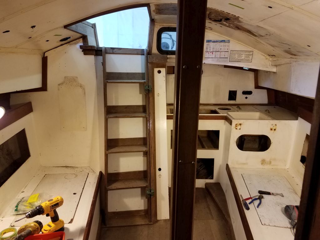
(page 115 of 167)

Scupper 10

< Back to Scupper

Tuesday

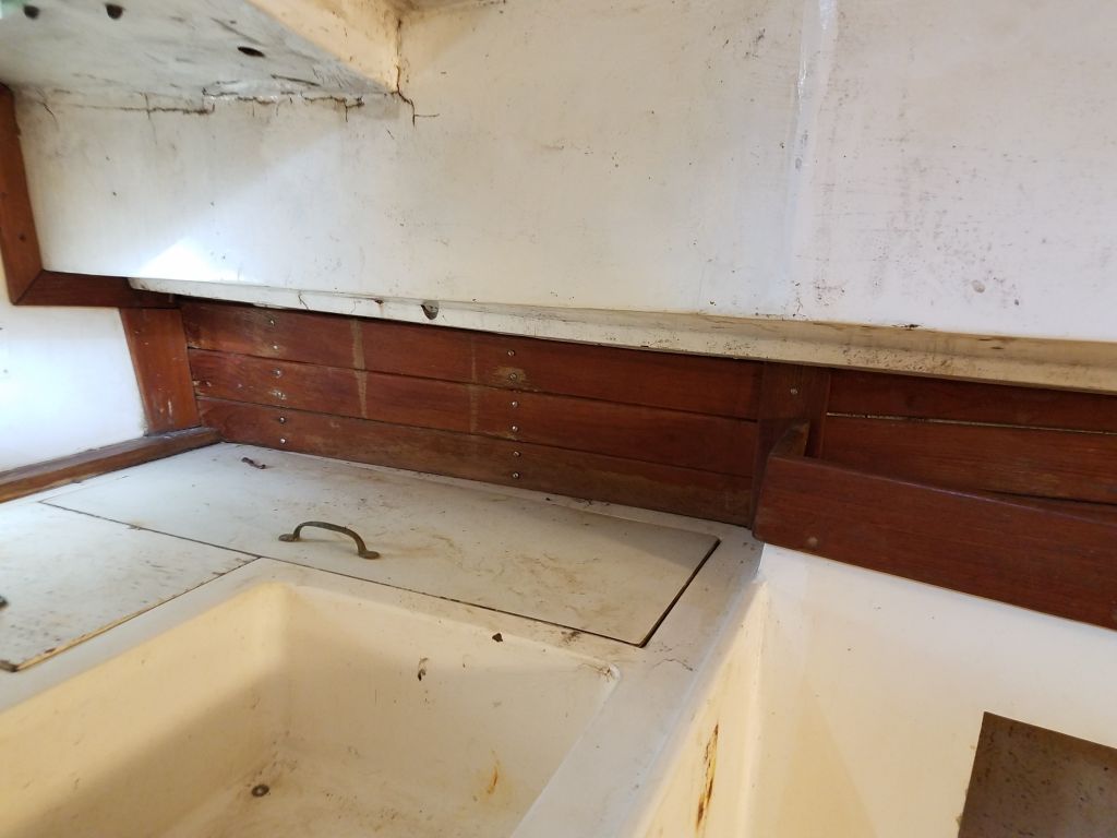
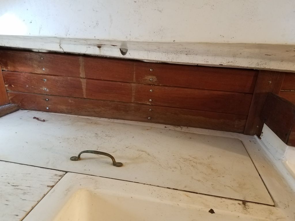
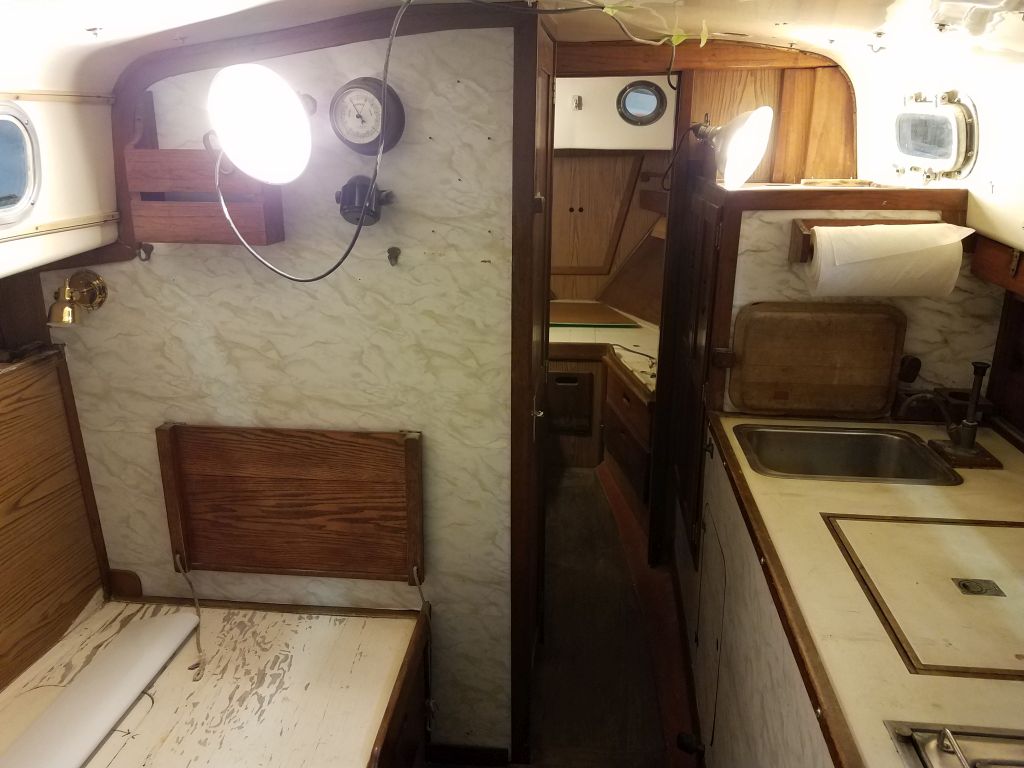
Continuing in the main cabin, I removed the ceiling strips from the starboard side, setting them aside for later attention.  I was still considering how much of the remaining trim to remove–fiddles, bulkhead trim, and the like–but for now I kept my focus on the major hardware and systems removal.  I was leaning towards removing all the trim for ease of interior preparations and trim refinishing, but I’d come back to that in the near future.

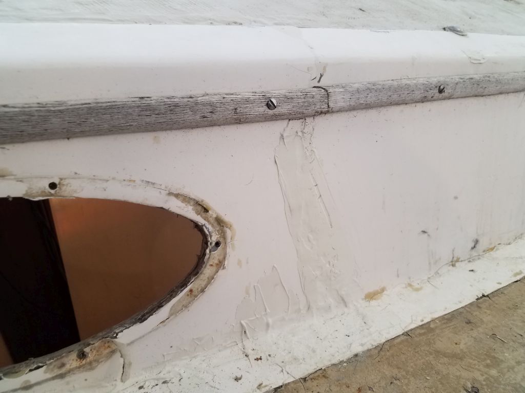
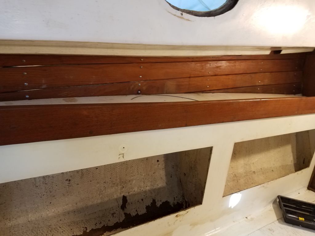
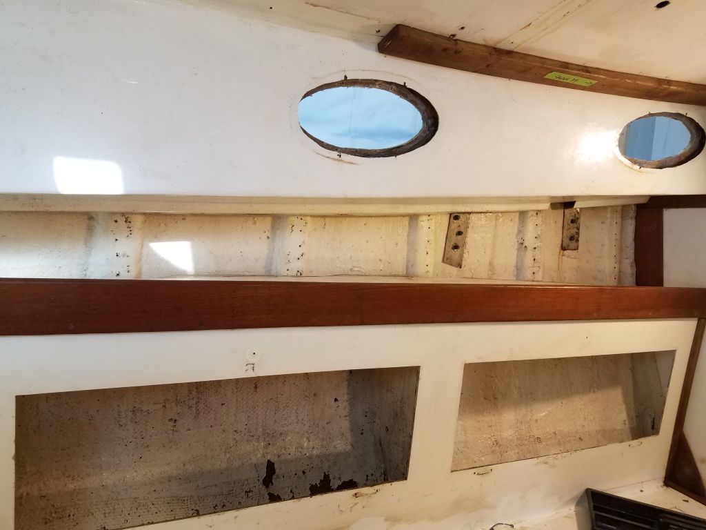
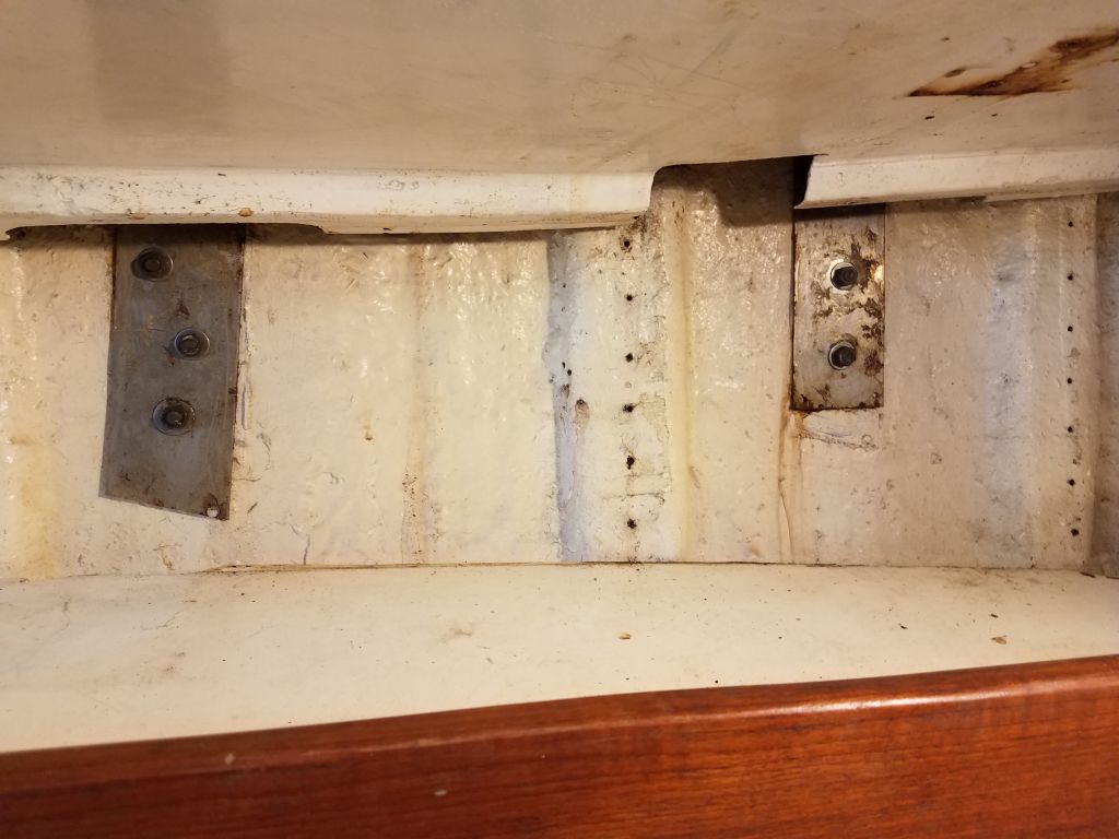
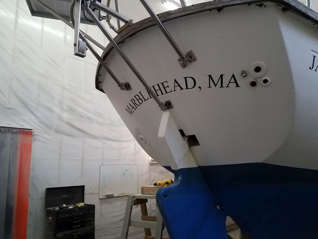
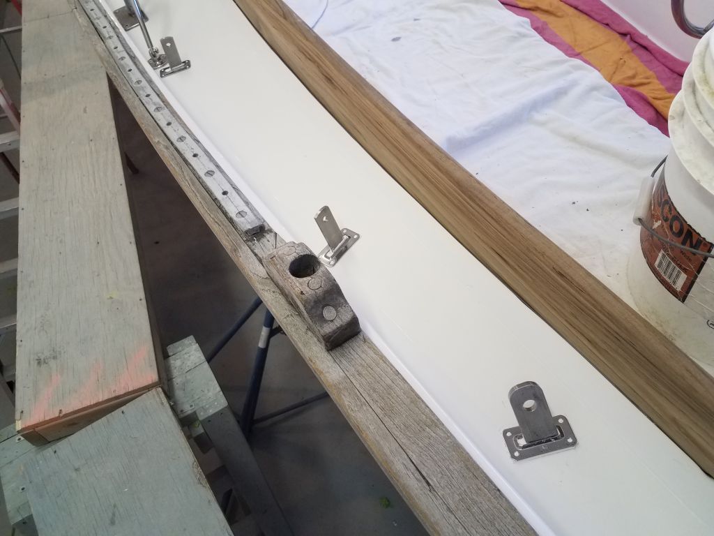
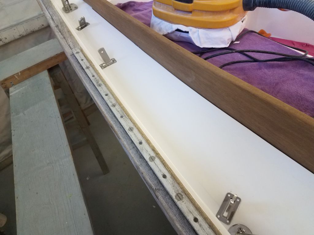
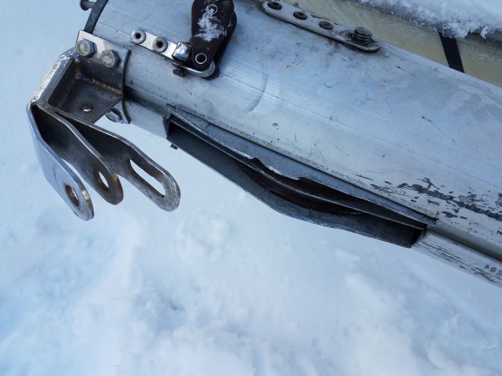
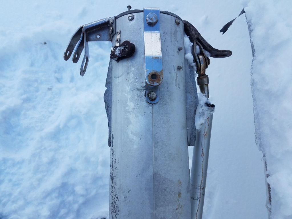
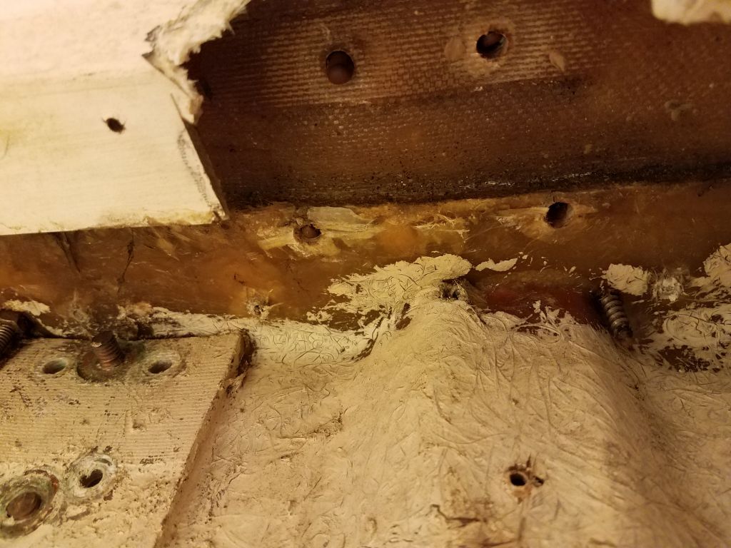
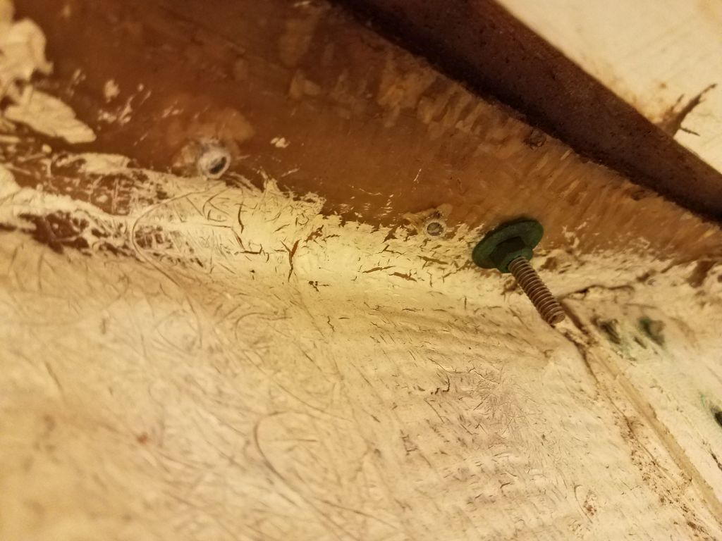
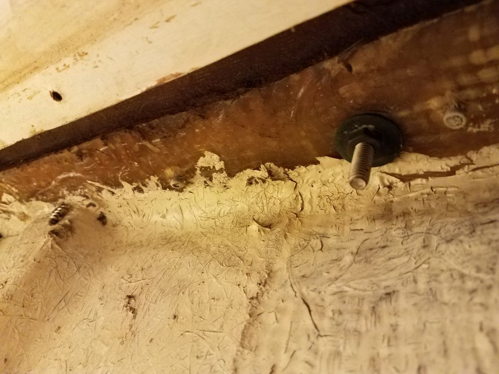
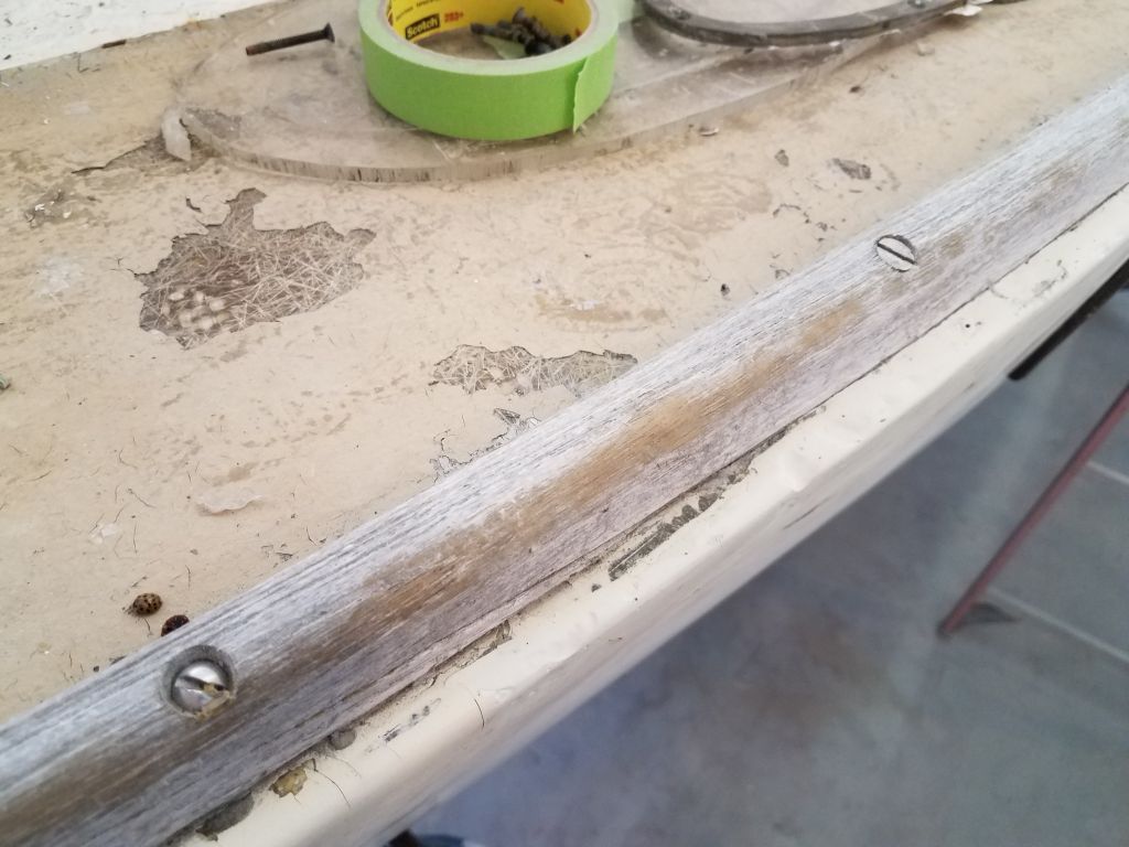
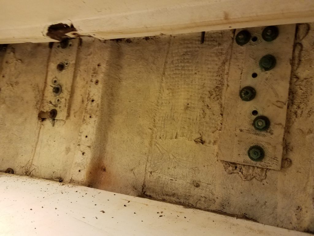
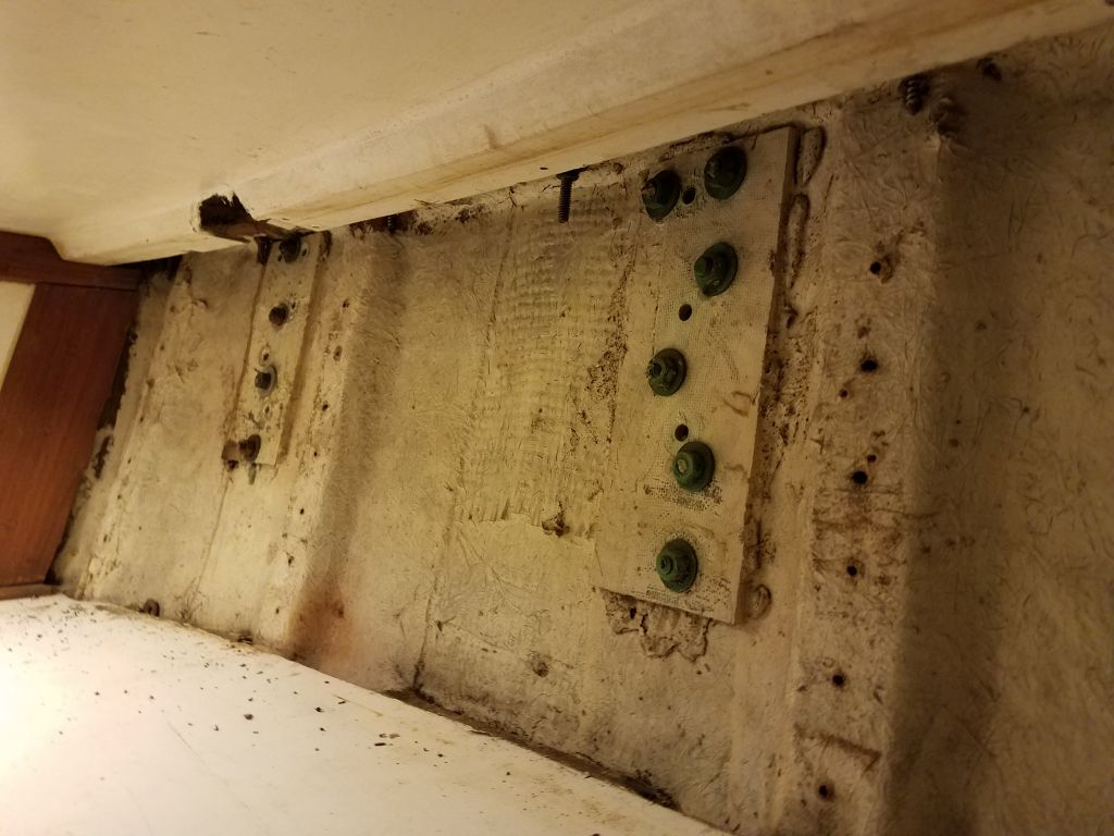
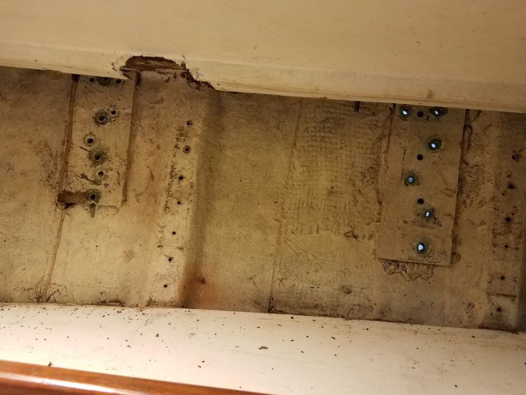
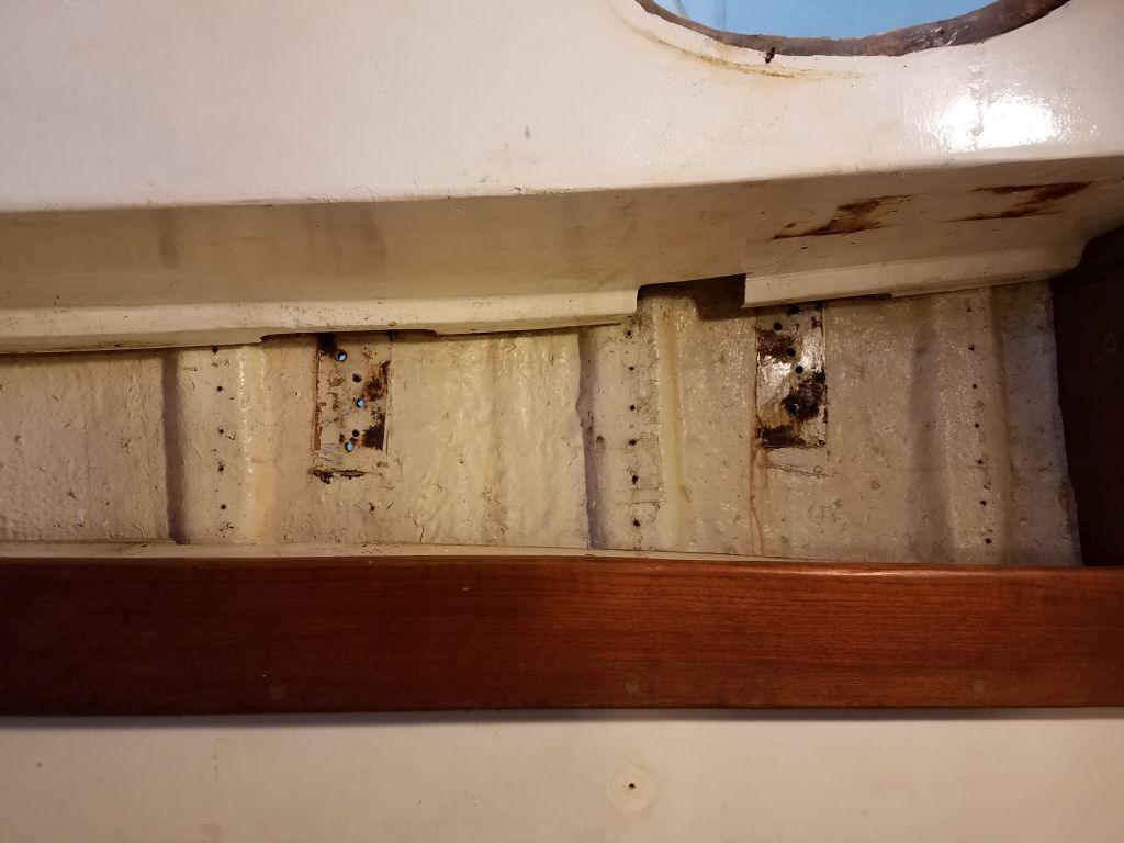
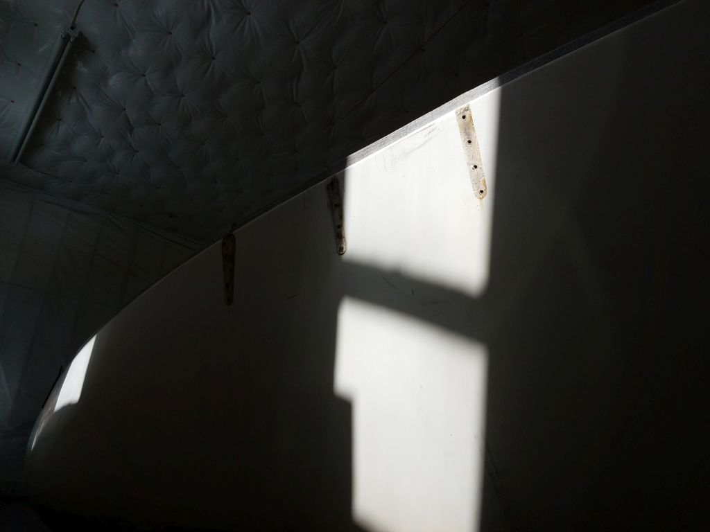
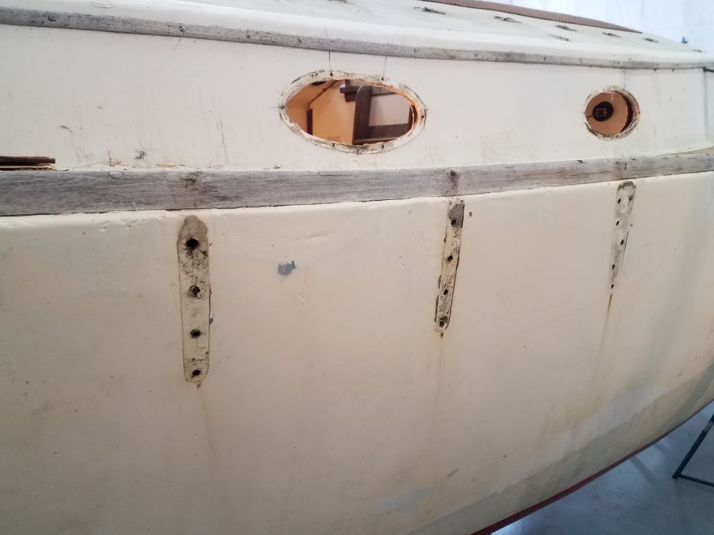
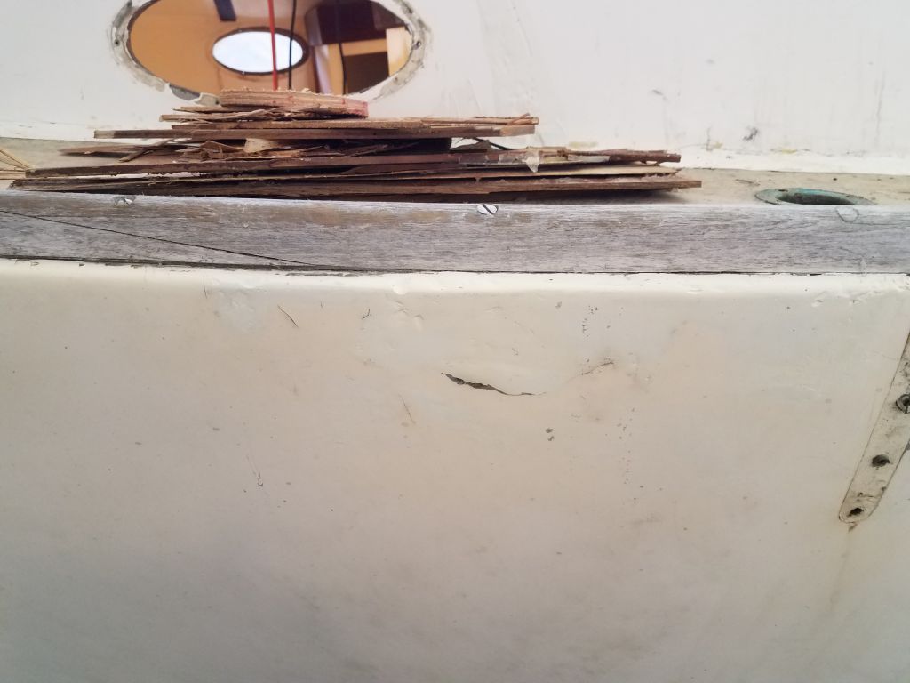
The full molded fiberglass deck liner was slightly different from side to side in terms of how much it hid the upper reaches of the hull, and on the starboard side access was a little better, so removing the ceiling here gave me the first good look at the hull-deck joint, which featured a molded inward hull flange, with the deck molding secured atop the flange.  There appeared to be adhesive or fiberglass between the hull and deck, and bronze bolts every 12″ or so.   Outside, the wooden toerails appeared to sit over the raised deck edge, hiding it from view, and the toerail fasteners looked to be screws that were not crucial to the hull-deck joint itself.  More on the toerails in due course, but as I worked around the boat it became increasingly clear that they were worn out, with exposed fasteners, gaping seams, and other issues, and that it would ultimately benefit the project to remove them for access to the hull-deck joint and for later replacement, possibly with a non-wood product to ease future maintenance concerns.  More on this coming up soon.

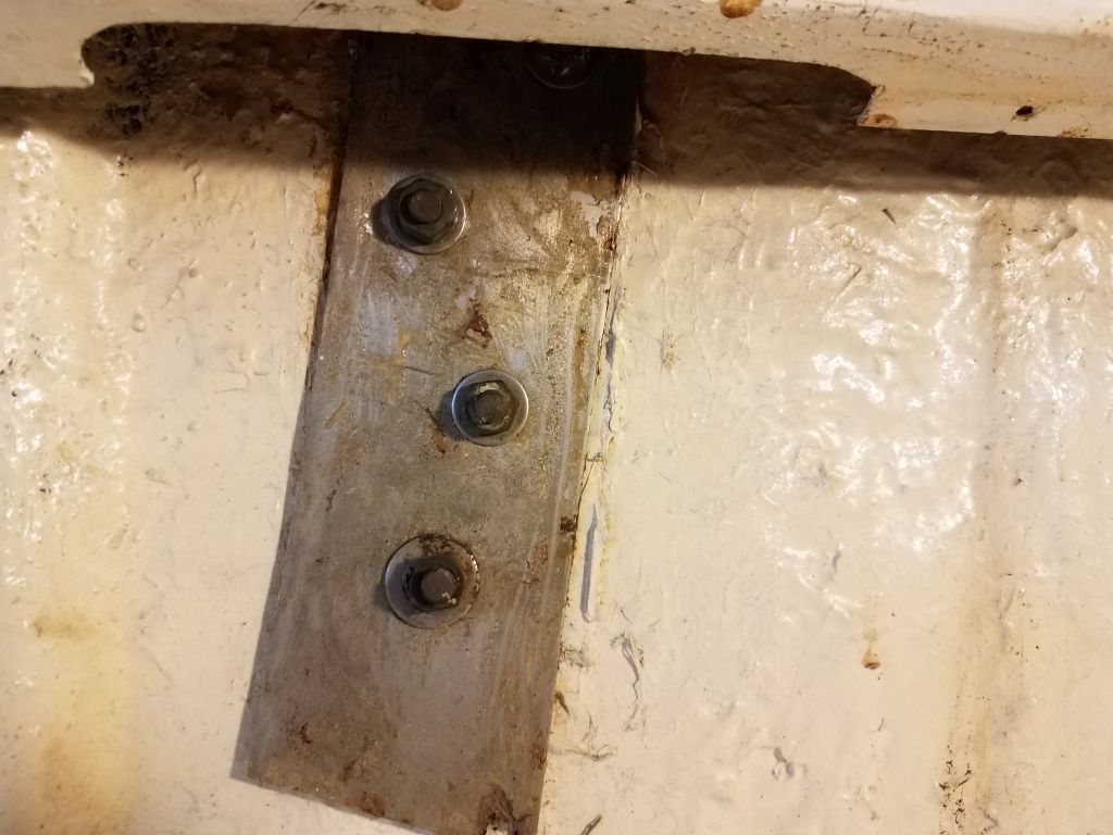
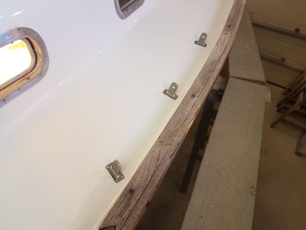
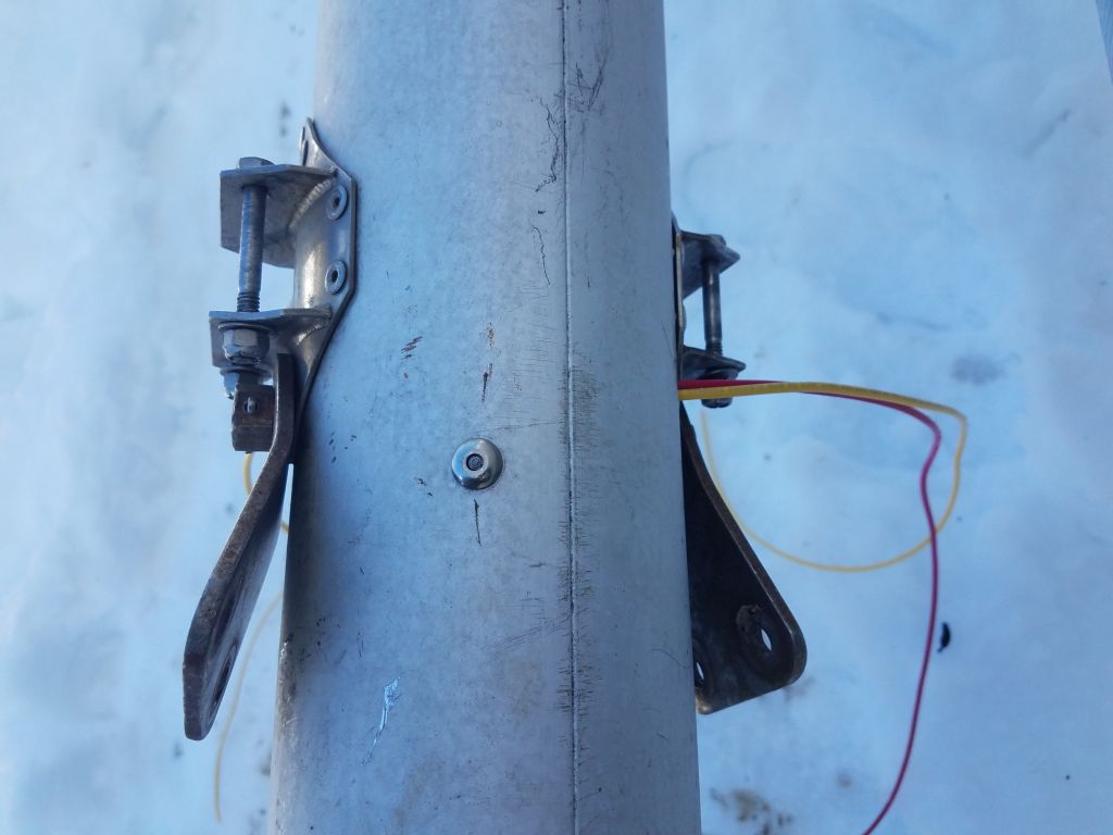
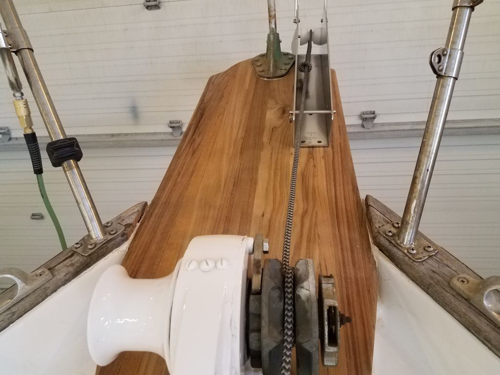
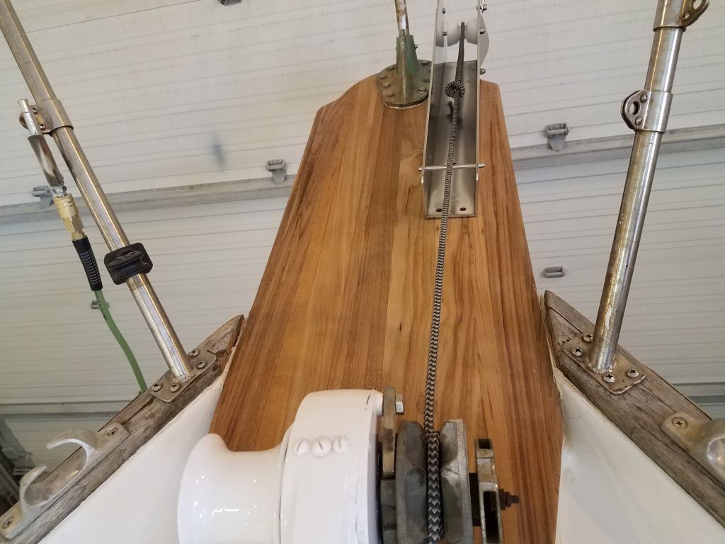
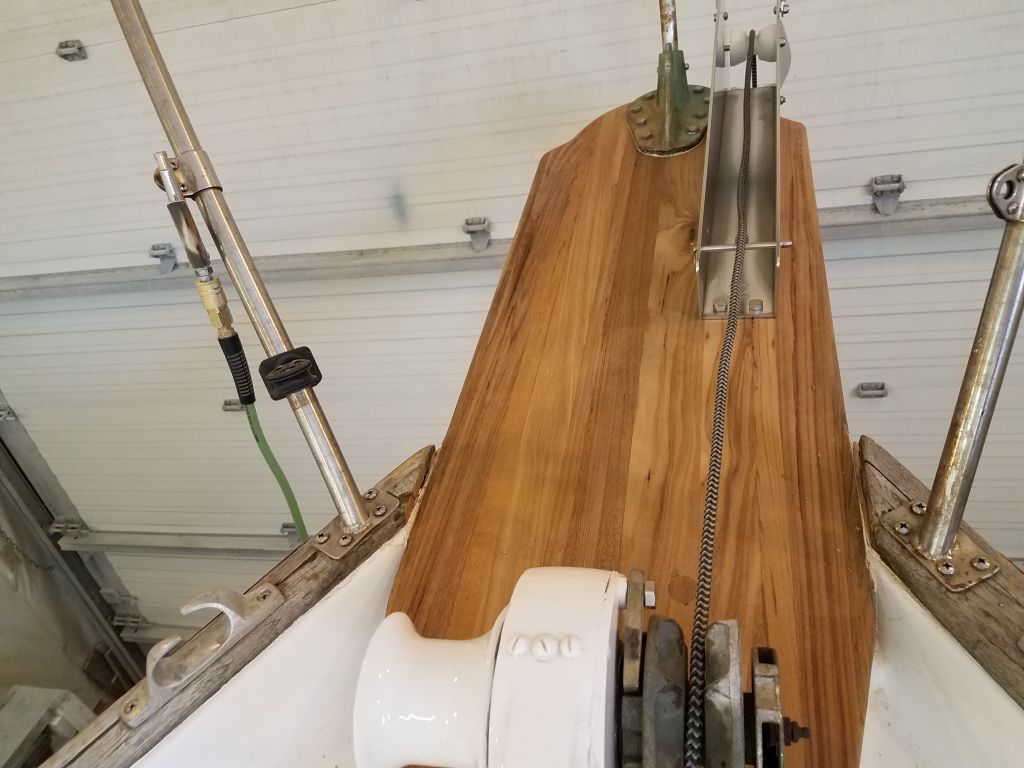
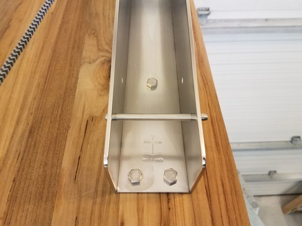
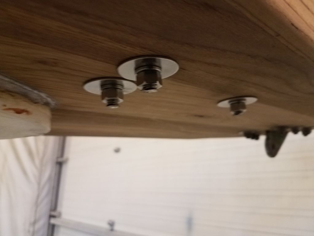
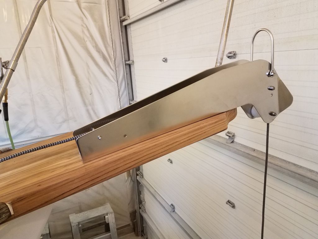
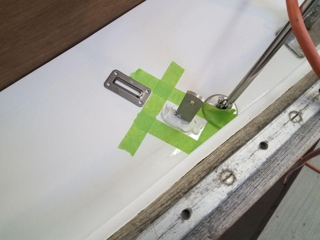
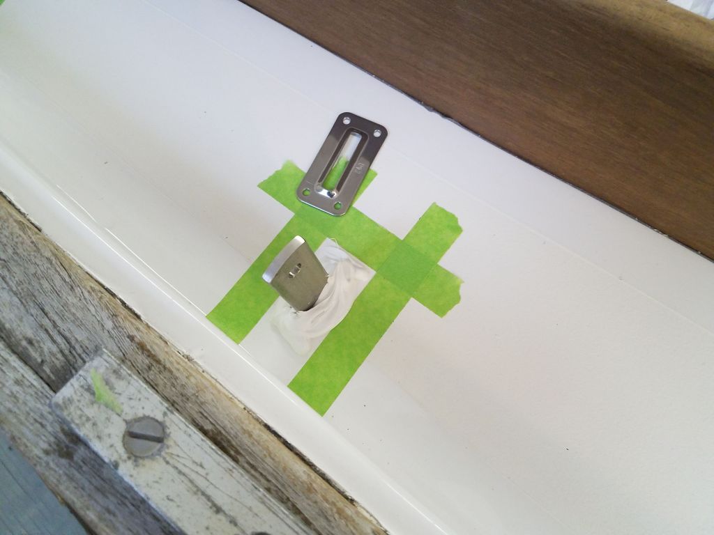
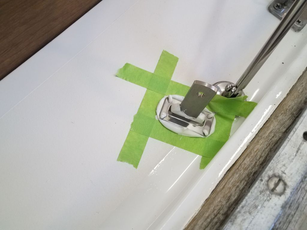
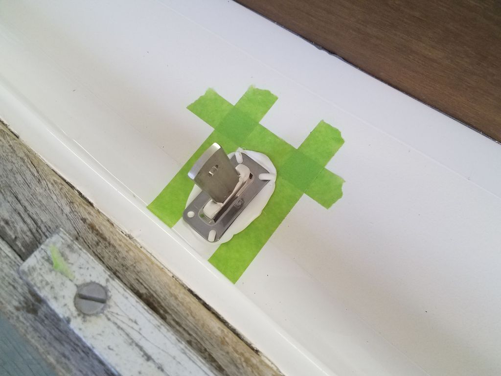
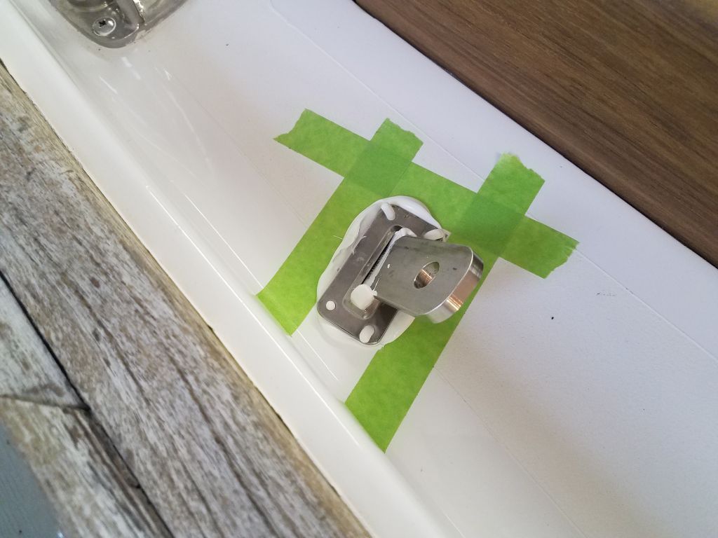
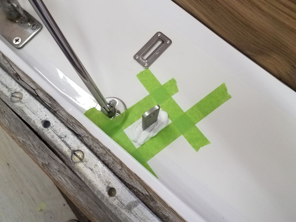
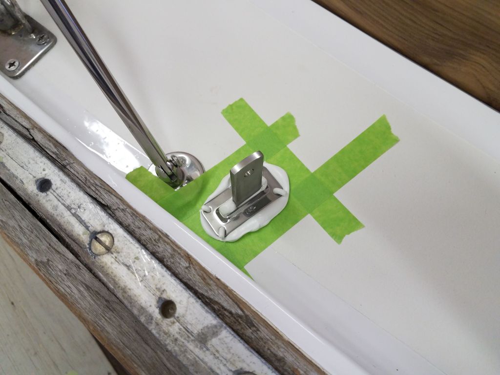
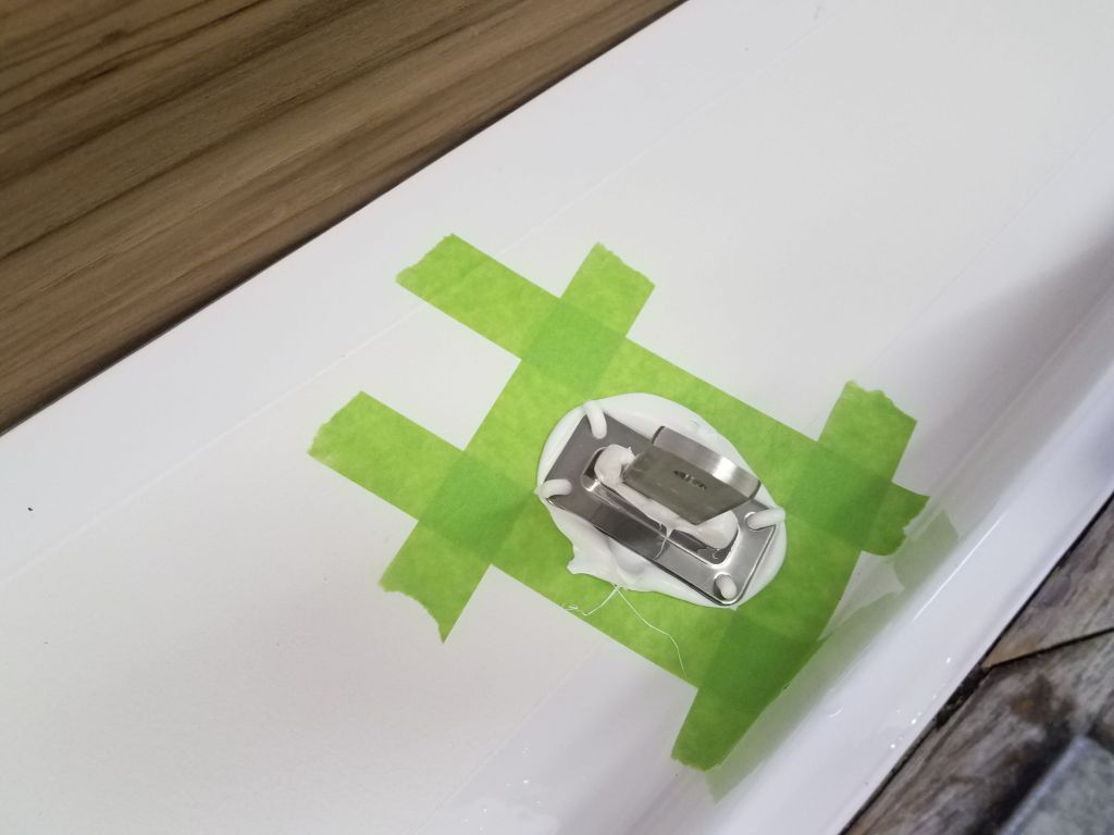
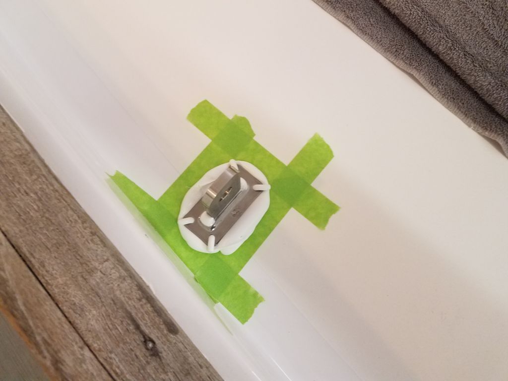
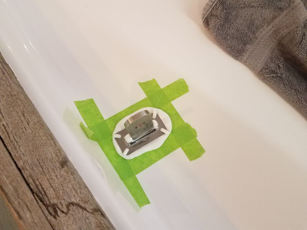
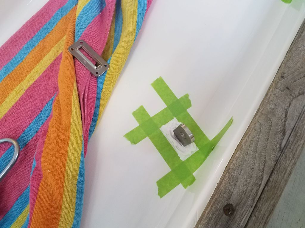
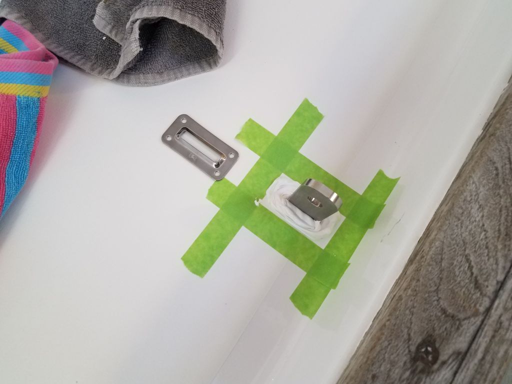
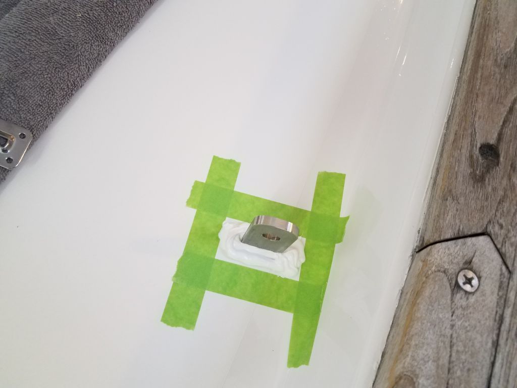
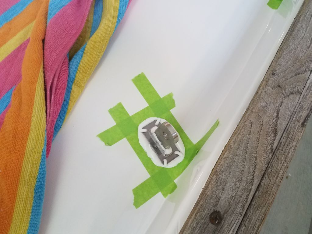
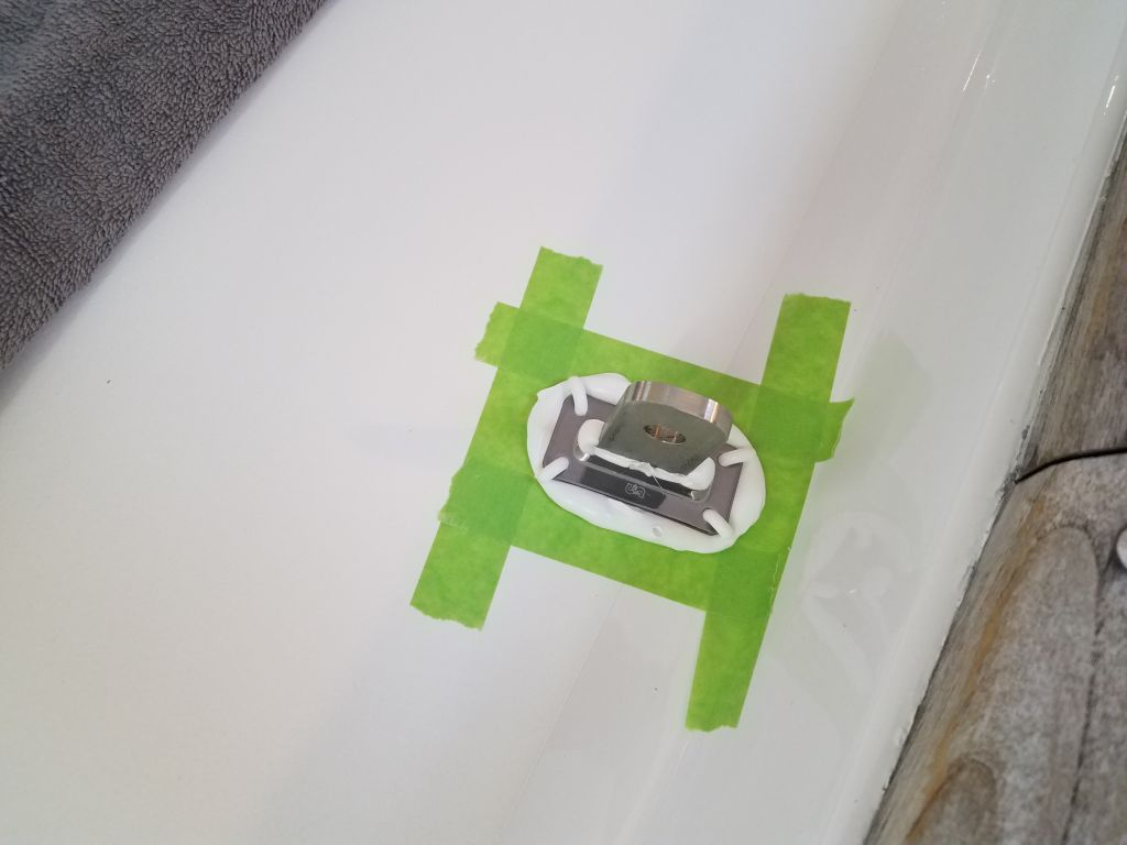
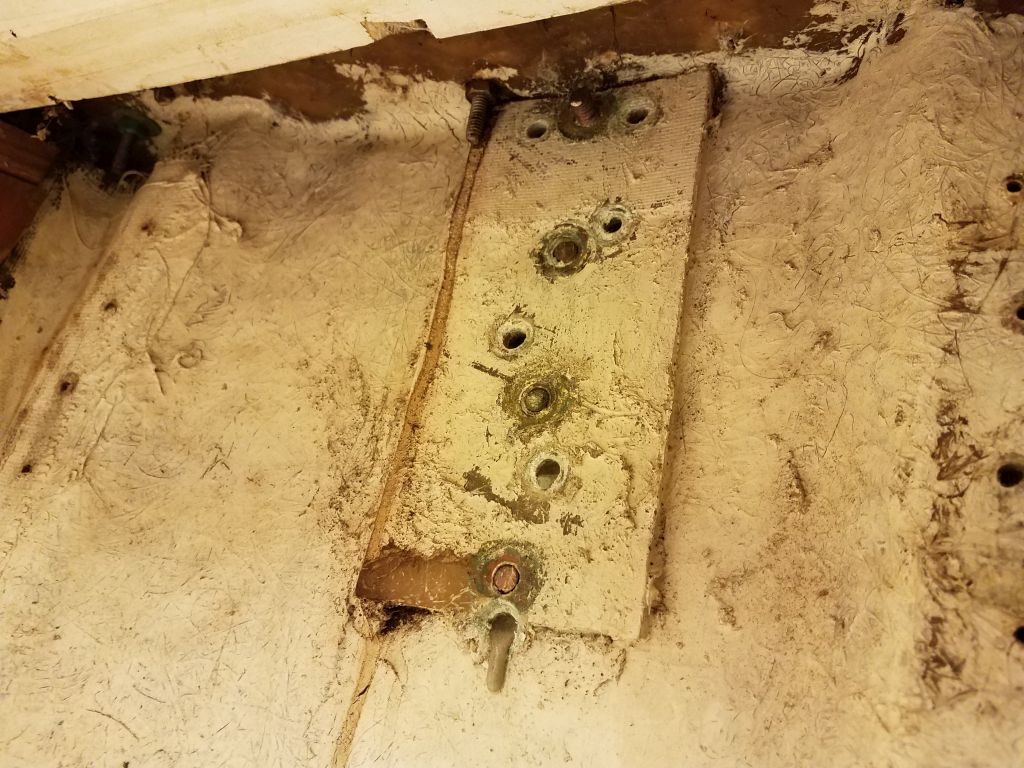
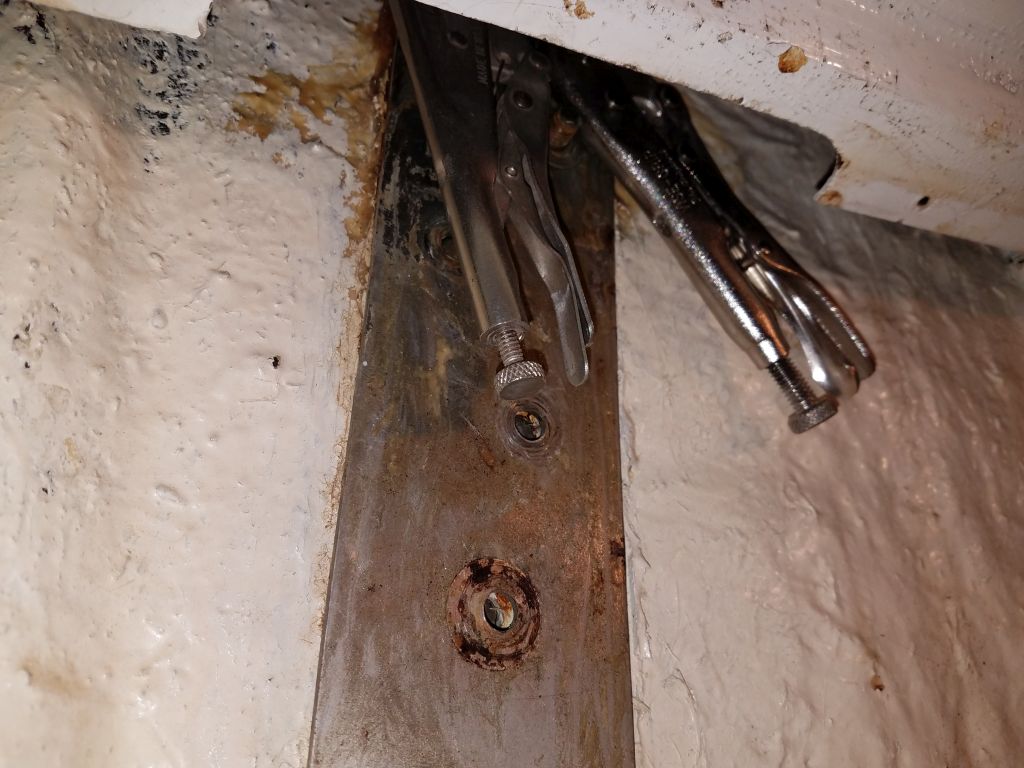
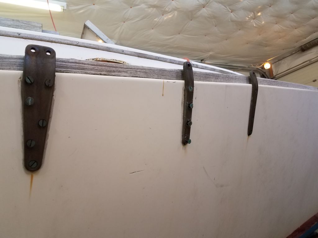
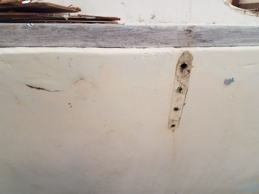
Now the chainplate fasteners were visible on both sides, and from inside the boat I removed the nuts, which mostly came off without spinning the bolts.  Where needed, I used locking pliers on the inside, then, from outside the boat, I removed the fasteners and the chainplates themselves.  The chainplates, made from cast bronze, were in good condition and would be reusable with only the most minor modicum of cleanup.

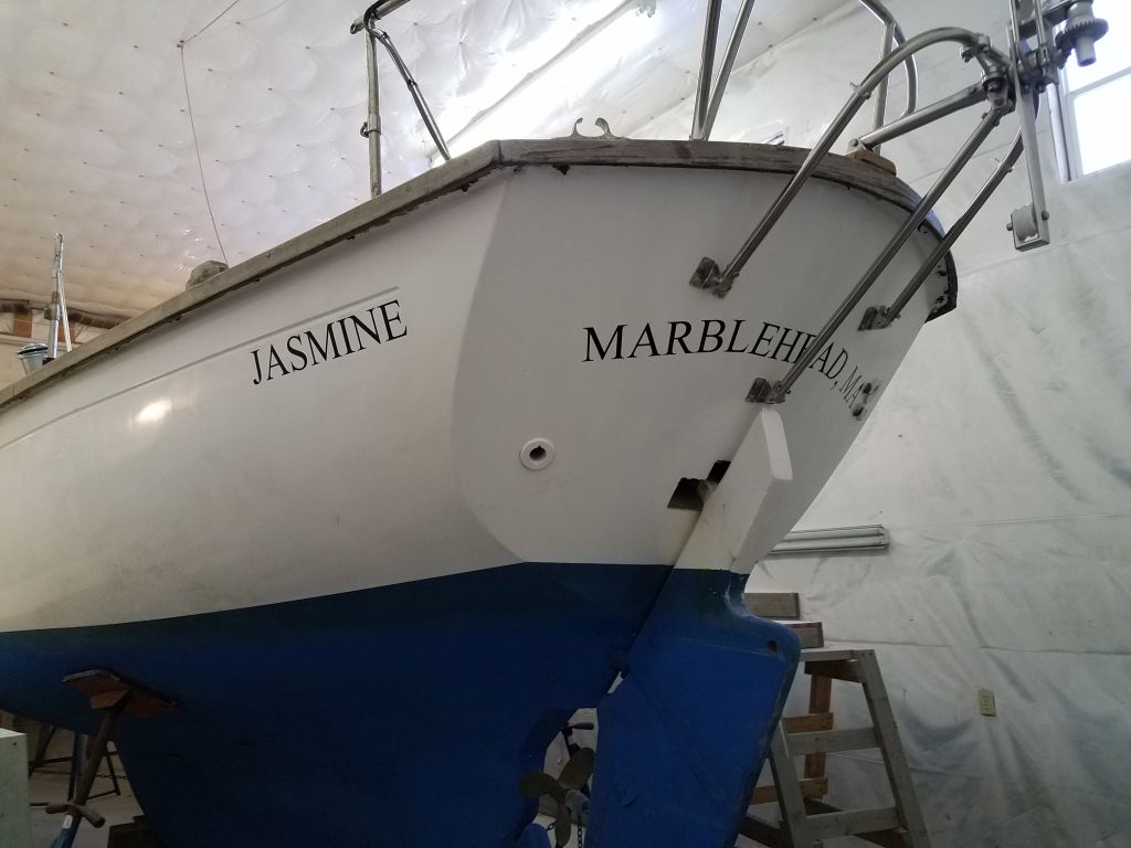
It was interesting to note that the port side was different from the starboard here.  There were multiple signs that the boat had been damaged on the port side, with easily visible repairs to the hull outside and at the toerail, and the fasteners and backing plates were different from side to side as well, with fiberglass backing plates to starboard (apparently original) and thin stainless steel backing plates to port.  None of this was a real surprise, but I found the differences interesting and worthy of note.  Obviously dealing with the previous rough repairs to the port side would form a significant part of the hull preparations to come soon.

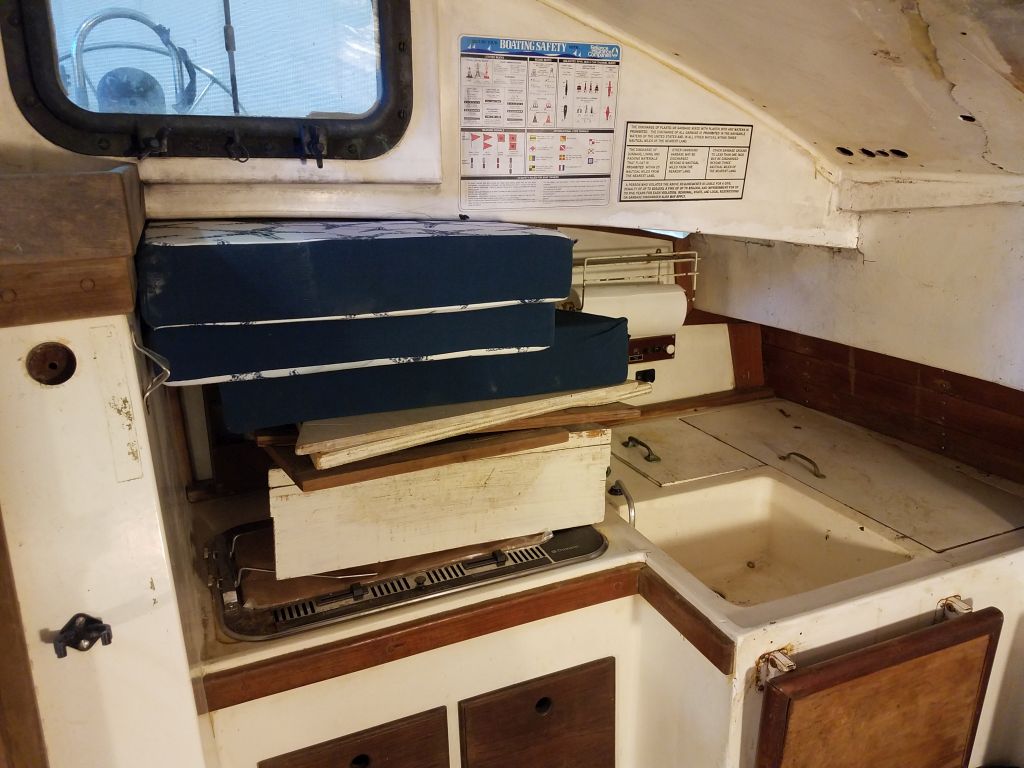
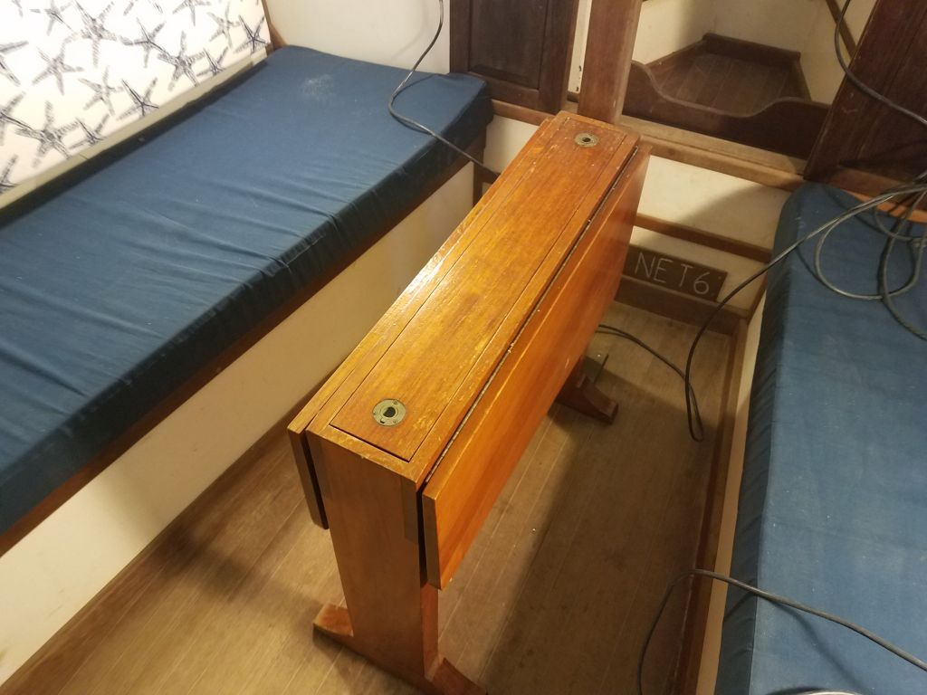
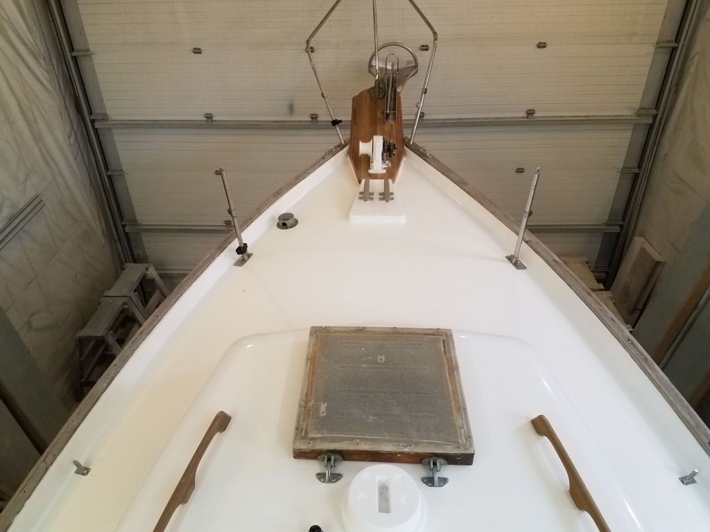
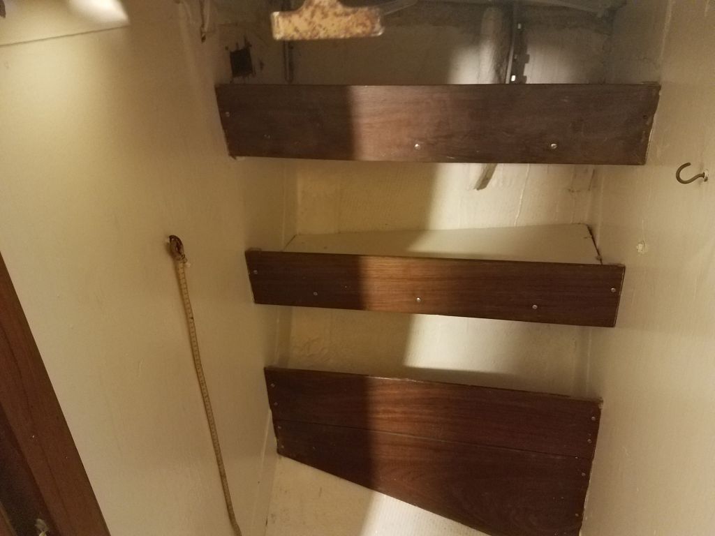
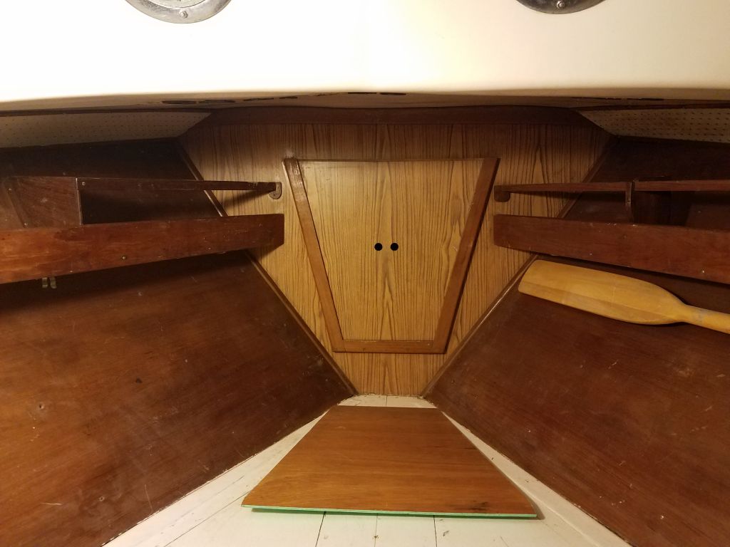
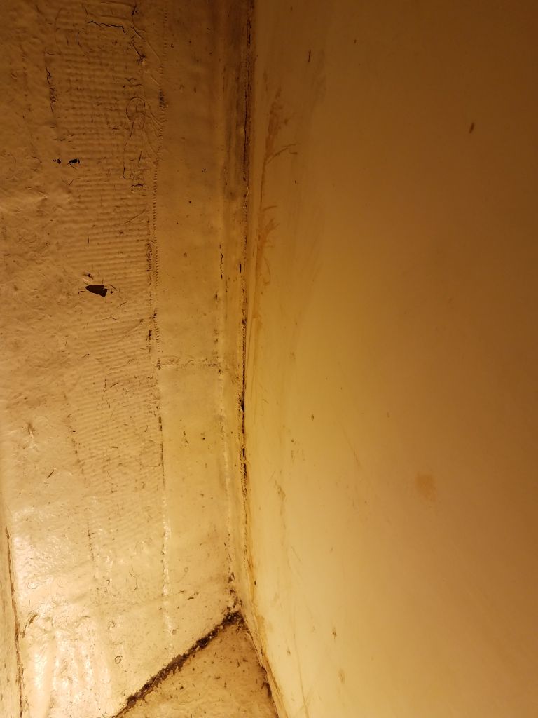
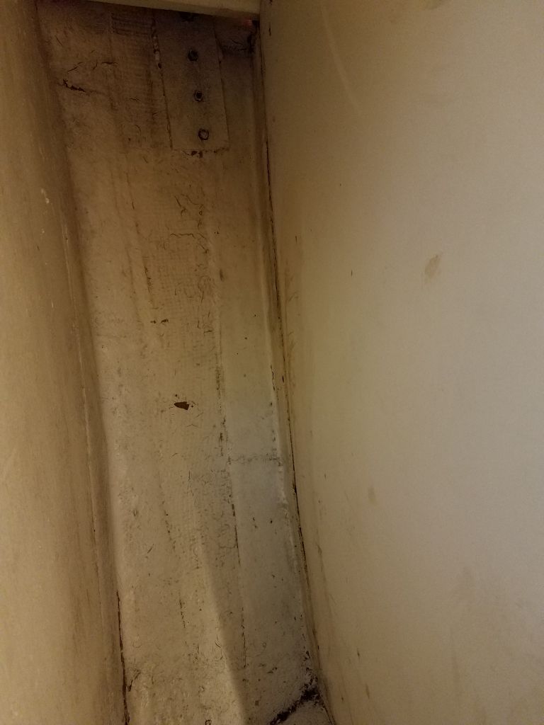
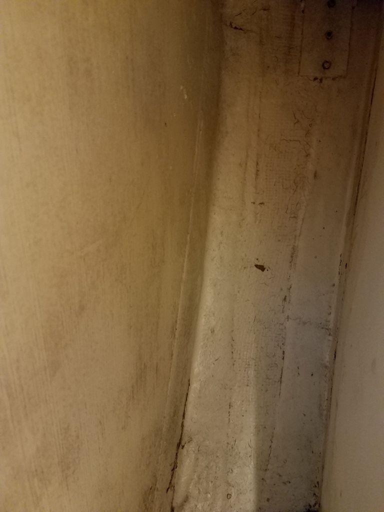
The fowardmost set of chainplates on each side were located inside hanging lockers in the forward cabin, part of the molded interior structure that formed the basis of the entire interior layout.  For better access here, now and later, I began by removing the wooden cabinet doors from the lockers.

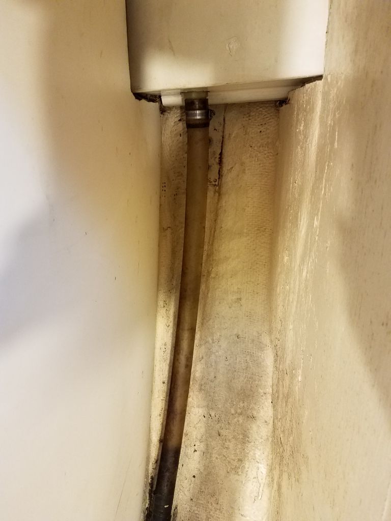
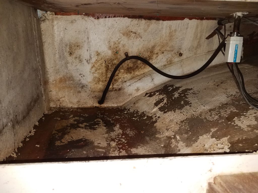
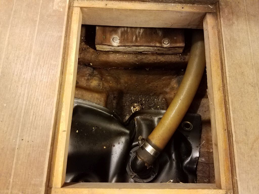
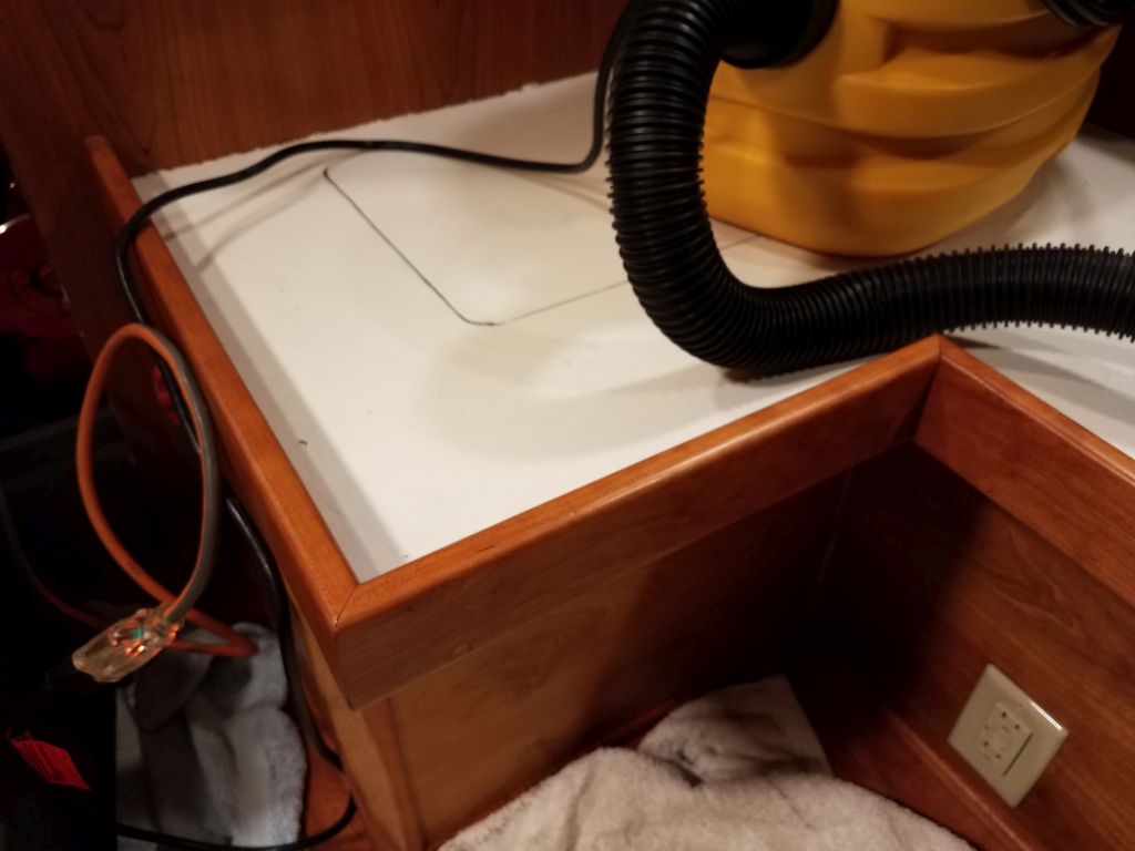
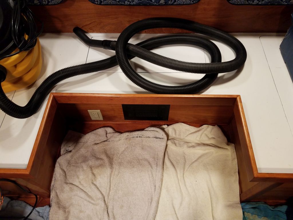
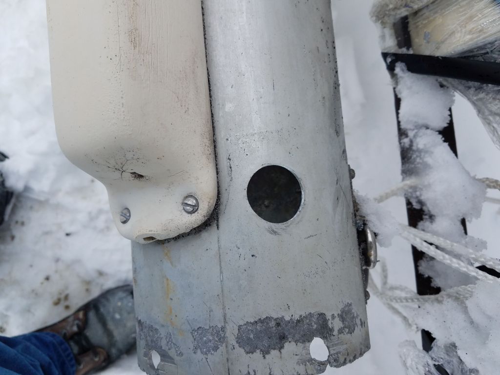
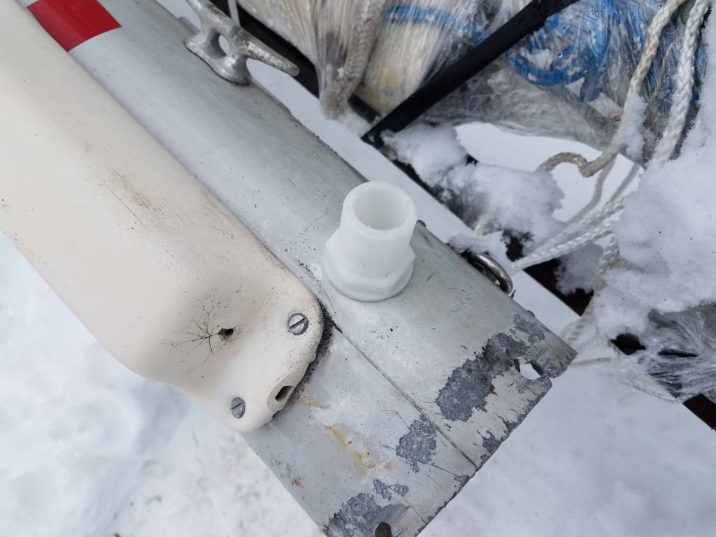
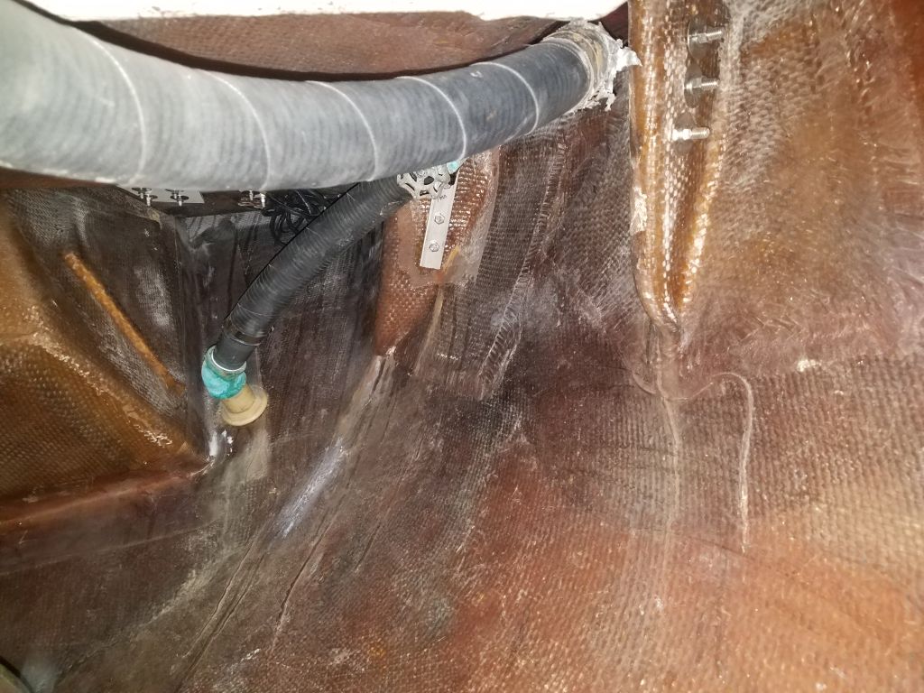
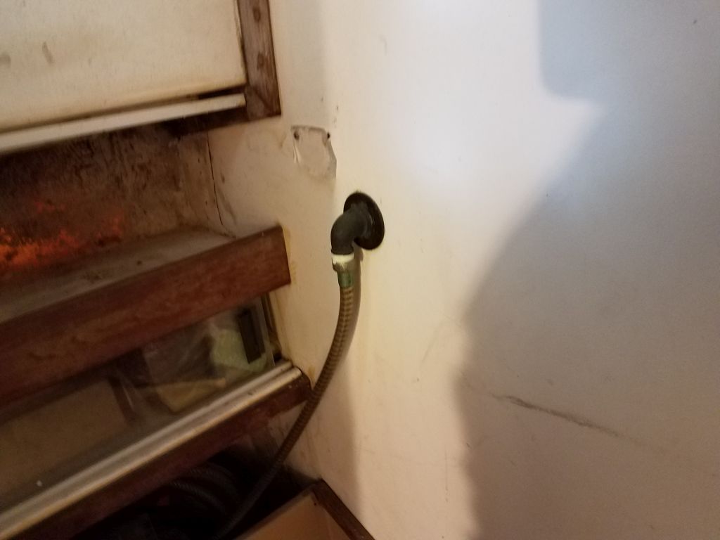
These lockers were deep and narrow, and the hull was at–or just beyond–the extent of my reach, one arm only as there was no way to get my shoulders through the locker openings.  To ease access on the port side, I started by removing the water fill hose, which was directly in the way of the chainplate bolts beyond.  Despite the long reach, I didn’t have too much trouble unclamping the hose from the deck fitting and pulling it free from the barb, but from there it got harder for a while.  The hose disappeared through the base of the locker, and reappeared in the bilge aft of the mast step.  Logically, I thought I could just pull the hose from one end or the other to remove it, but I soon discovered that it just wouldn’t move beyond a point, and I couldn’t pull it in either direction more than a few inches.

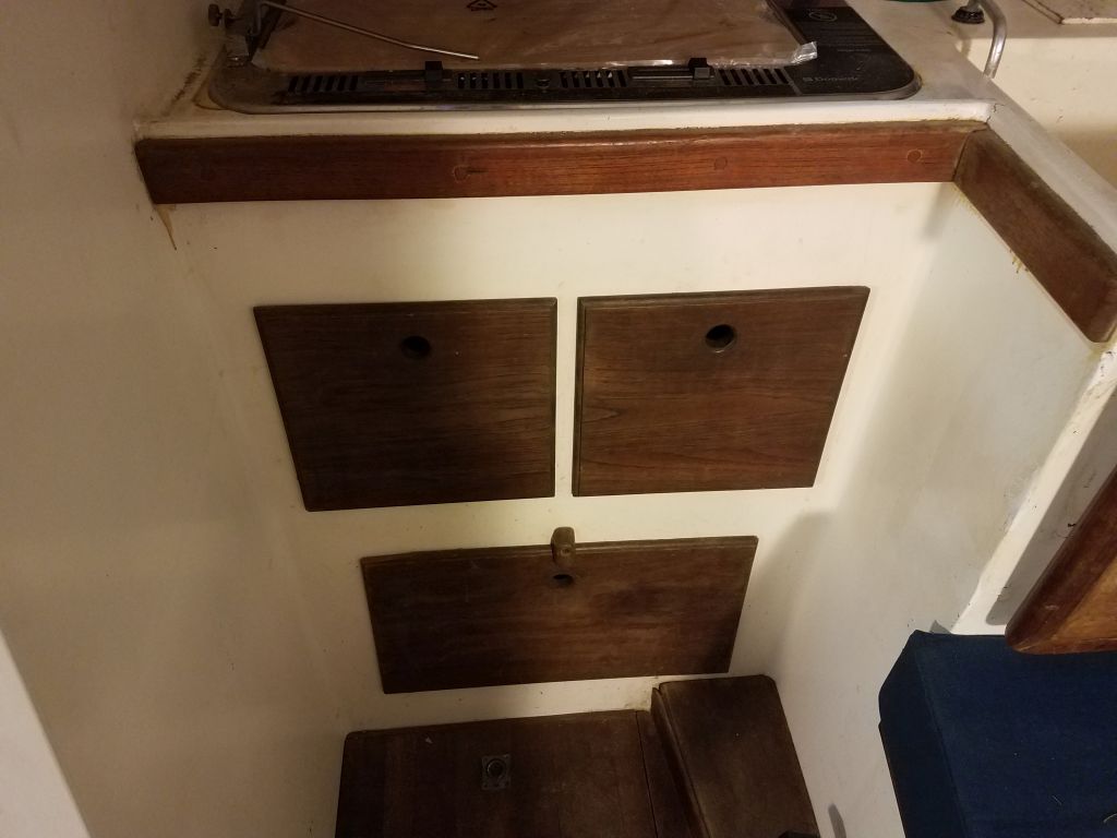
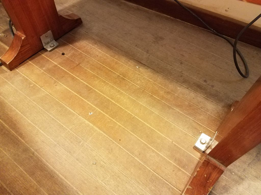
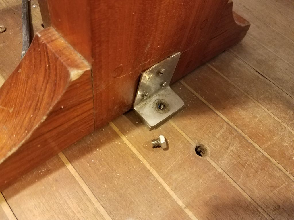
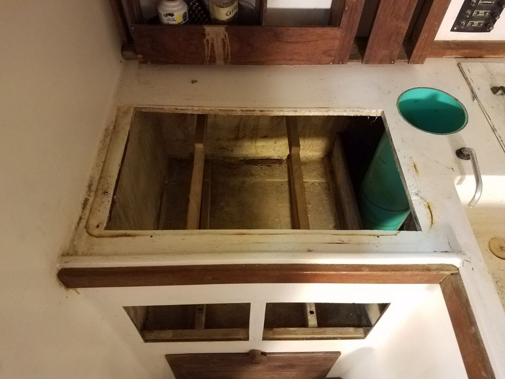
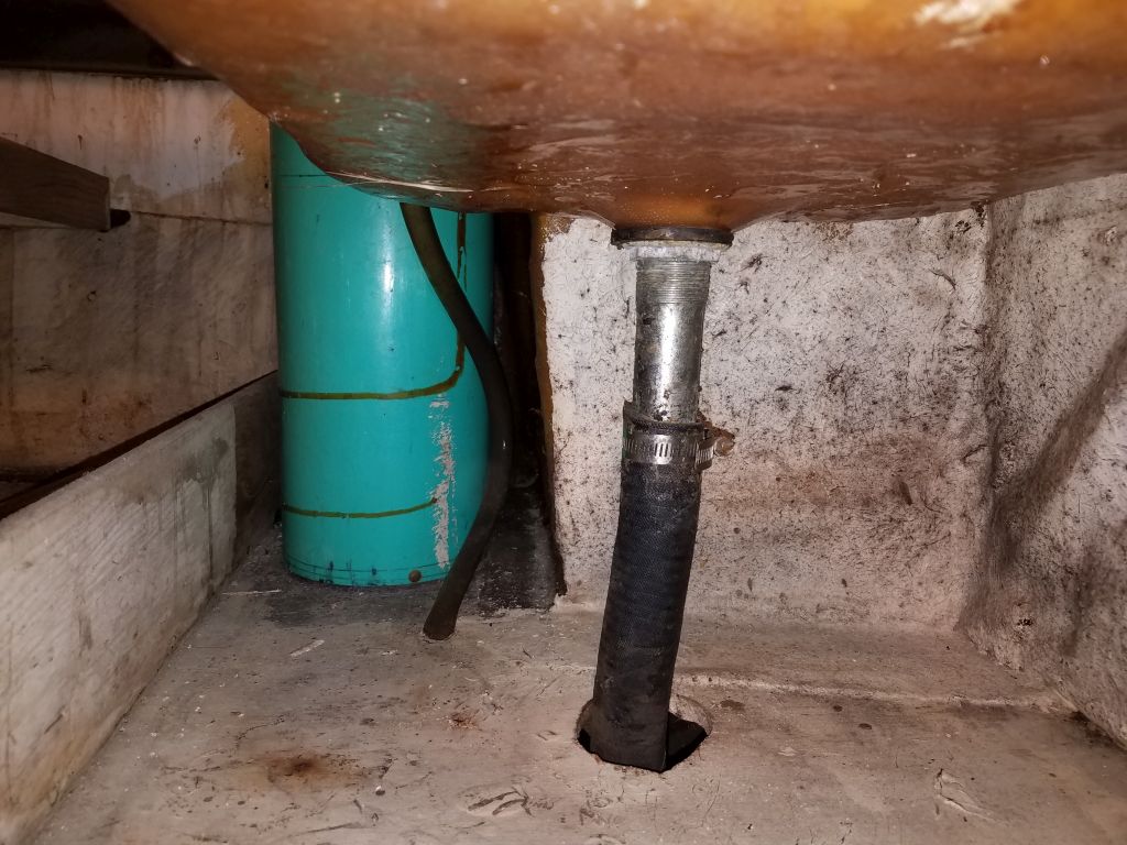
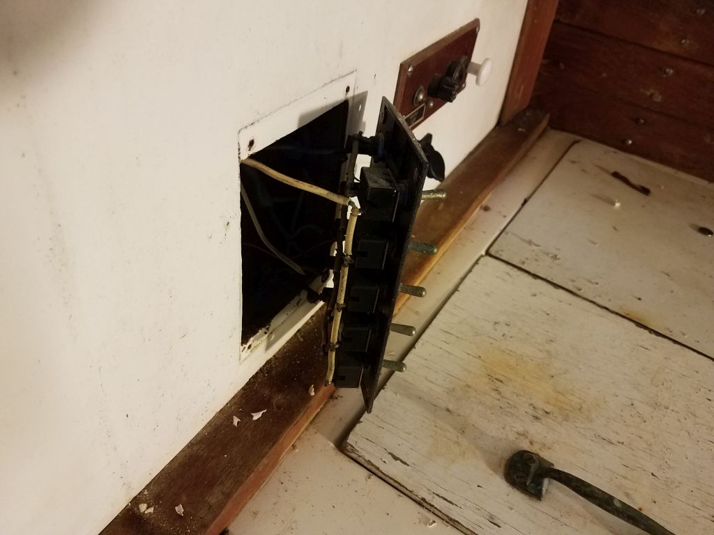
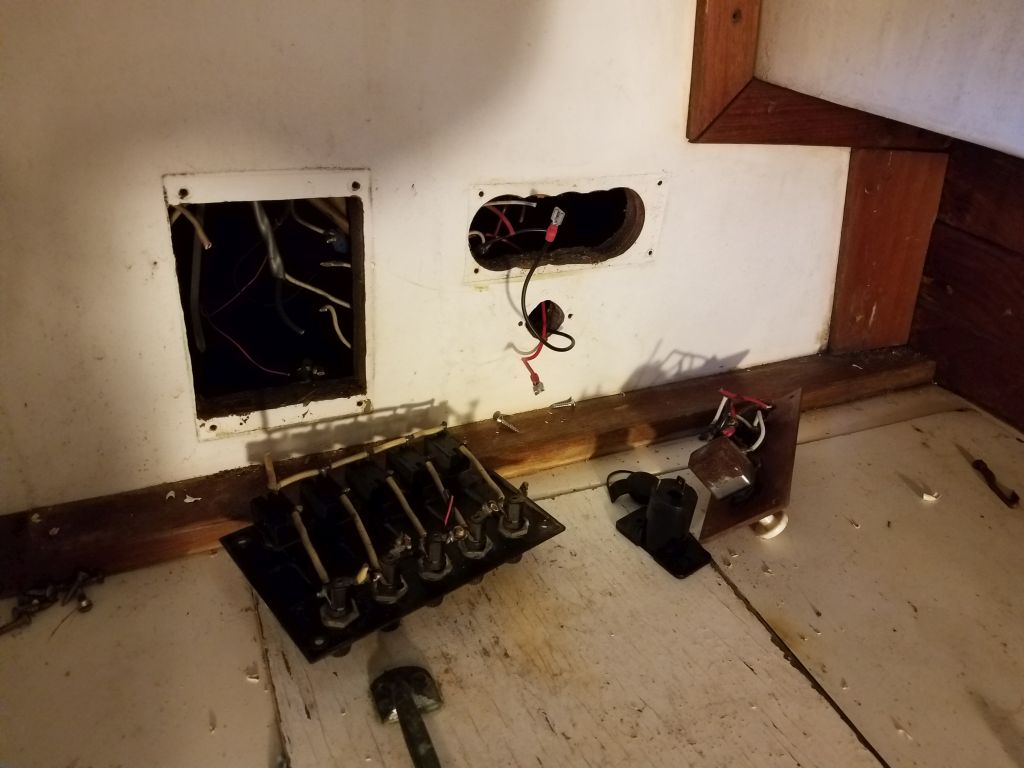
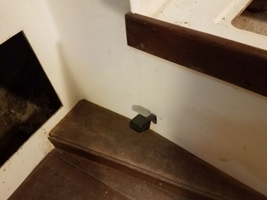
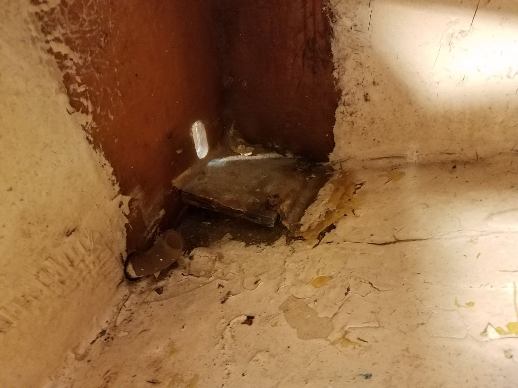
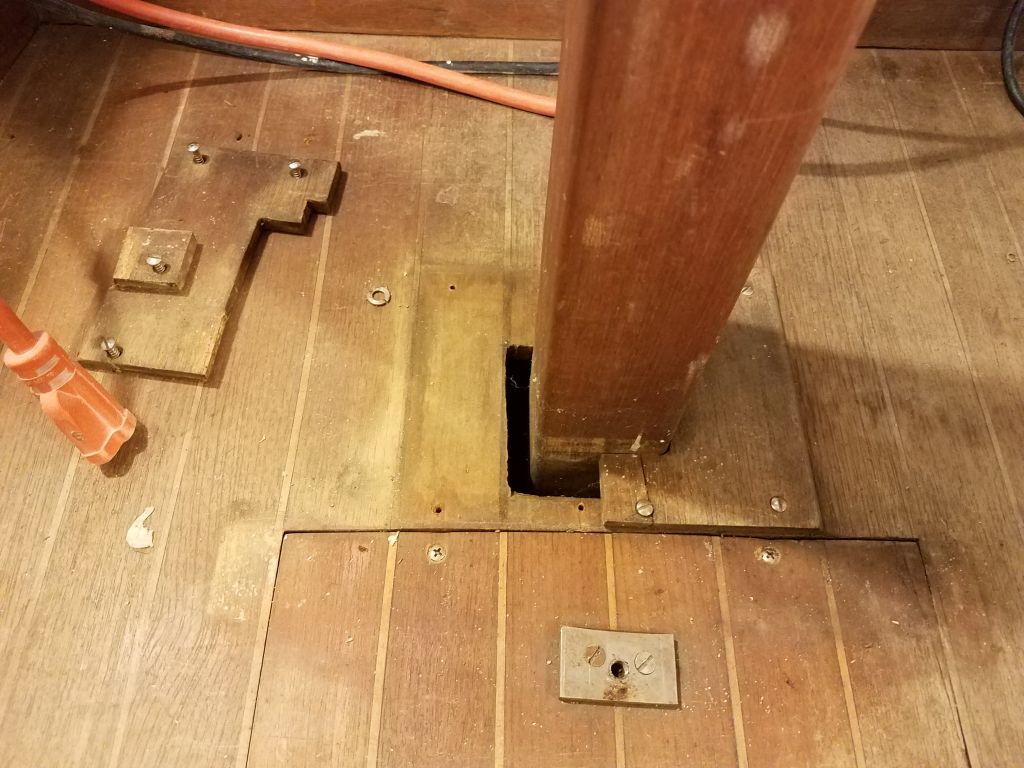
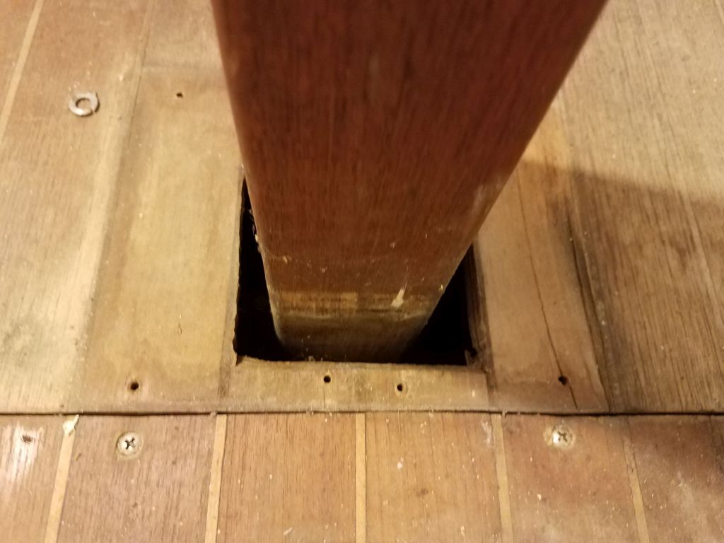
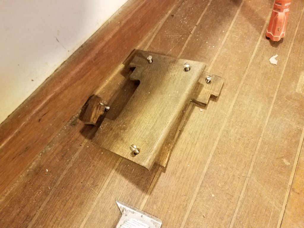
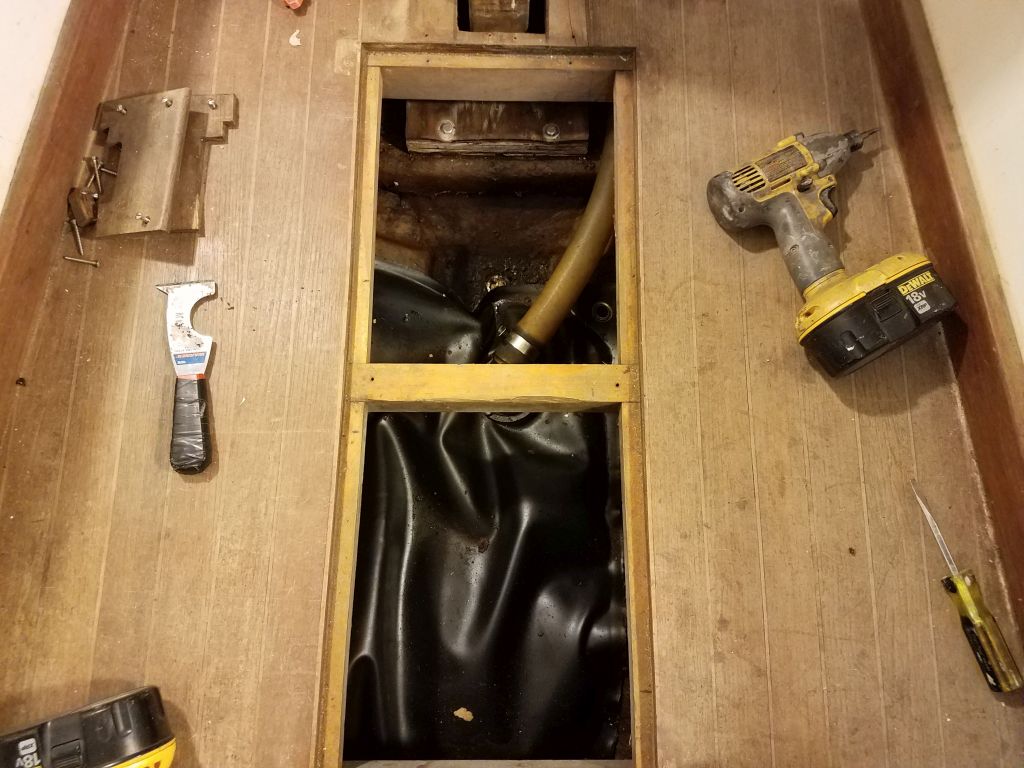
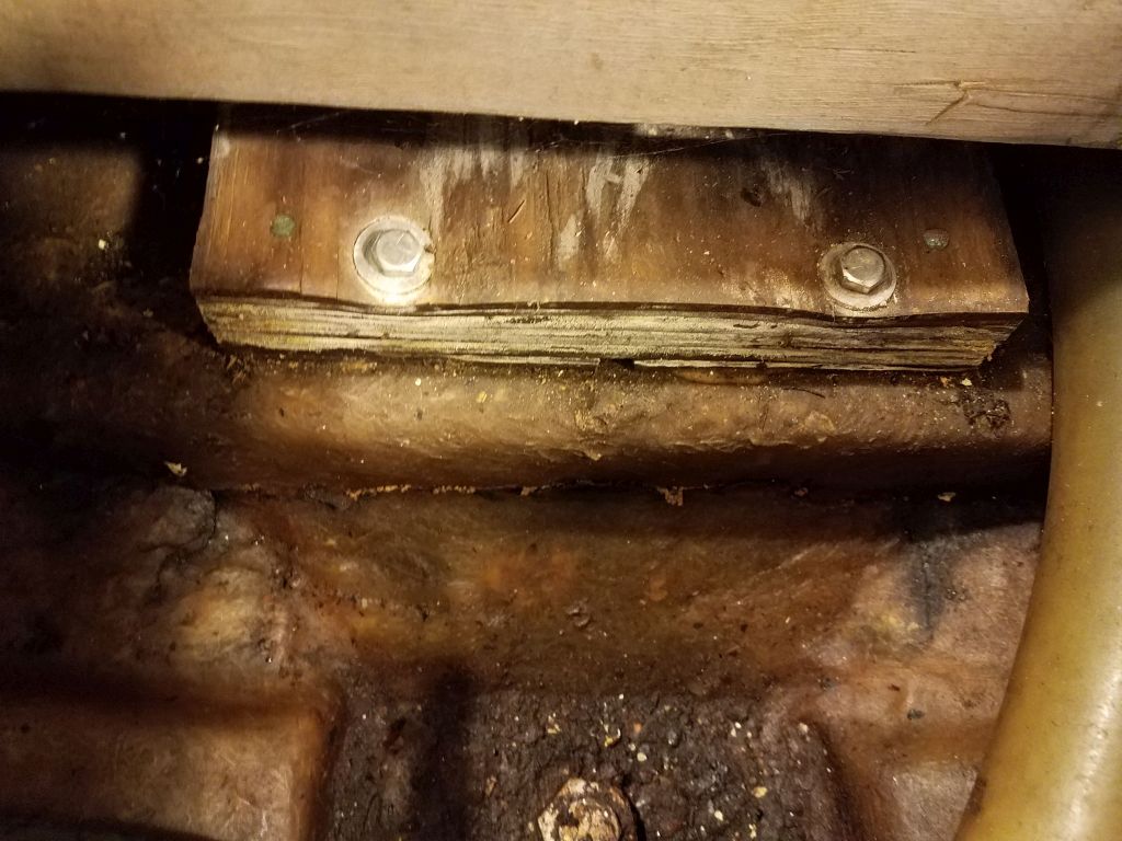
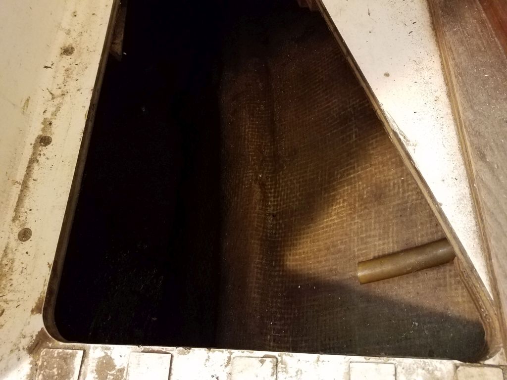
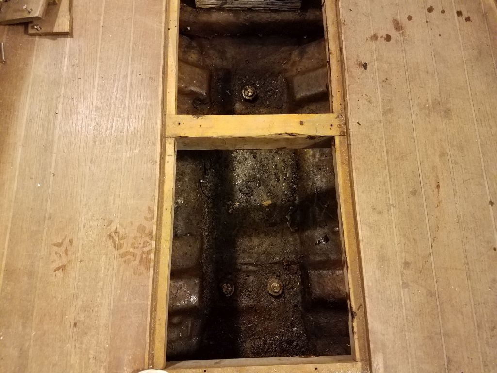
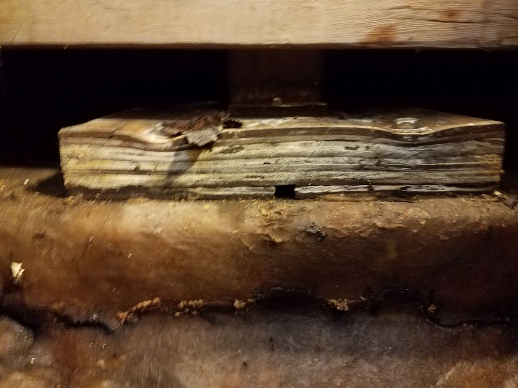
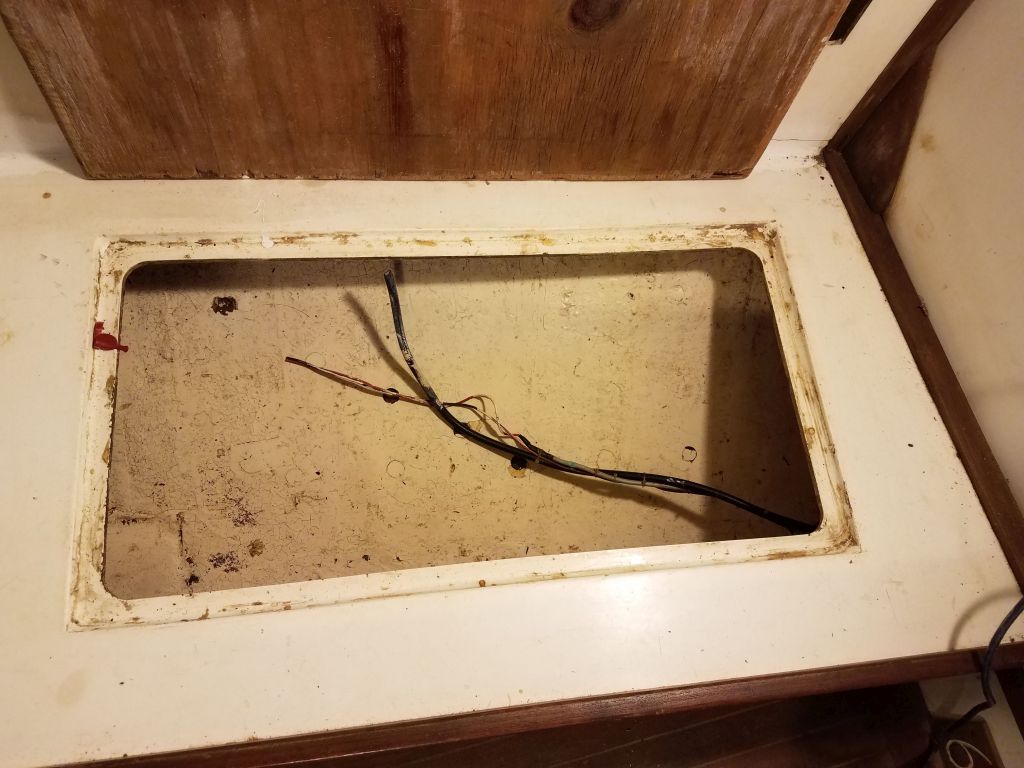
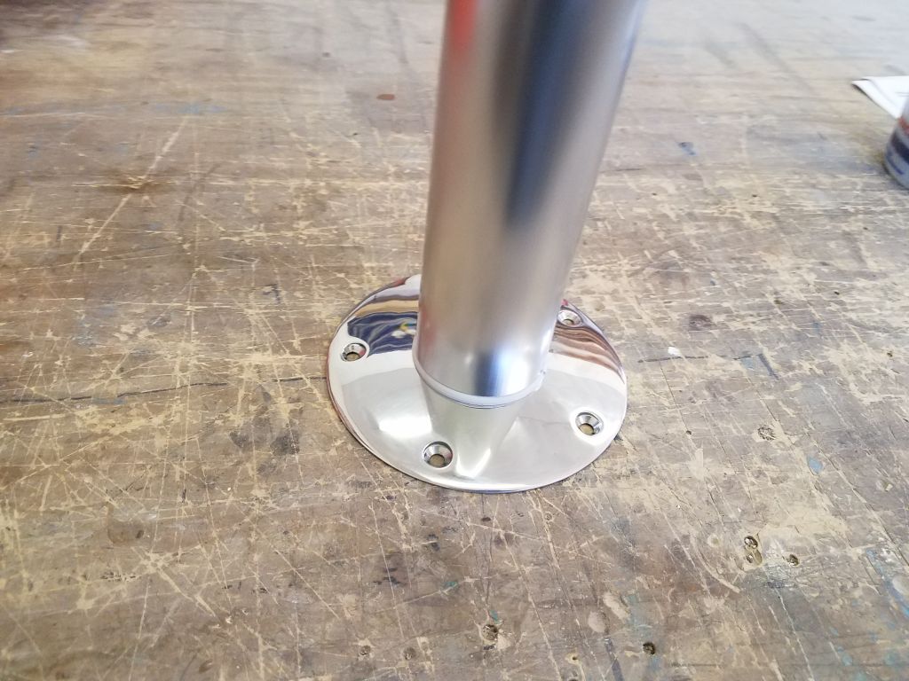
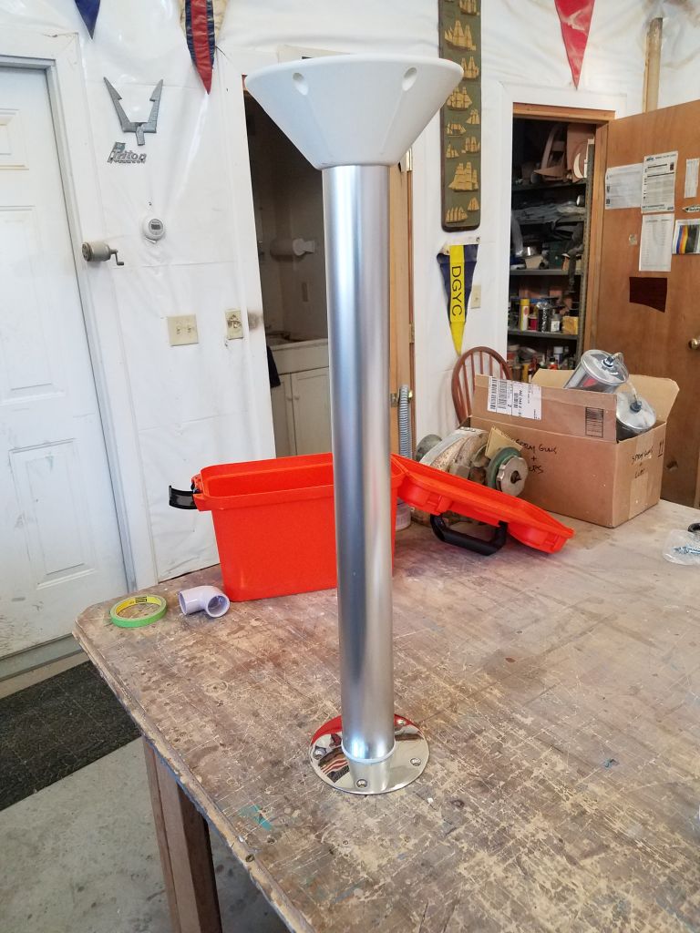
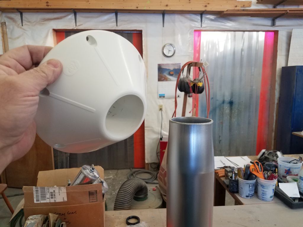
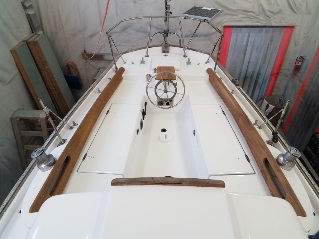
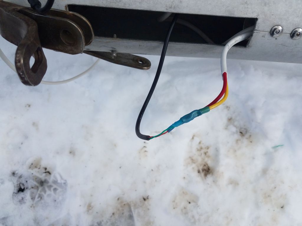
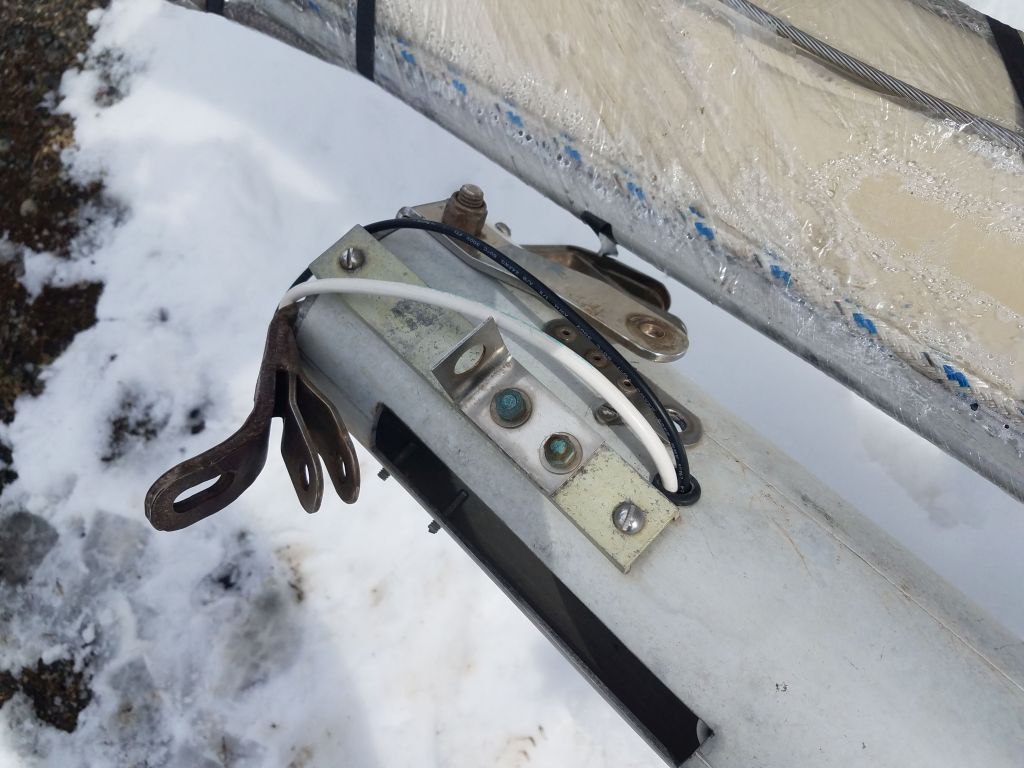
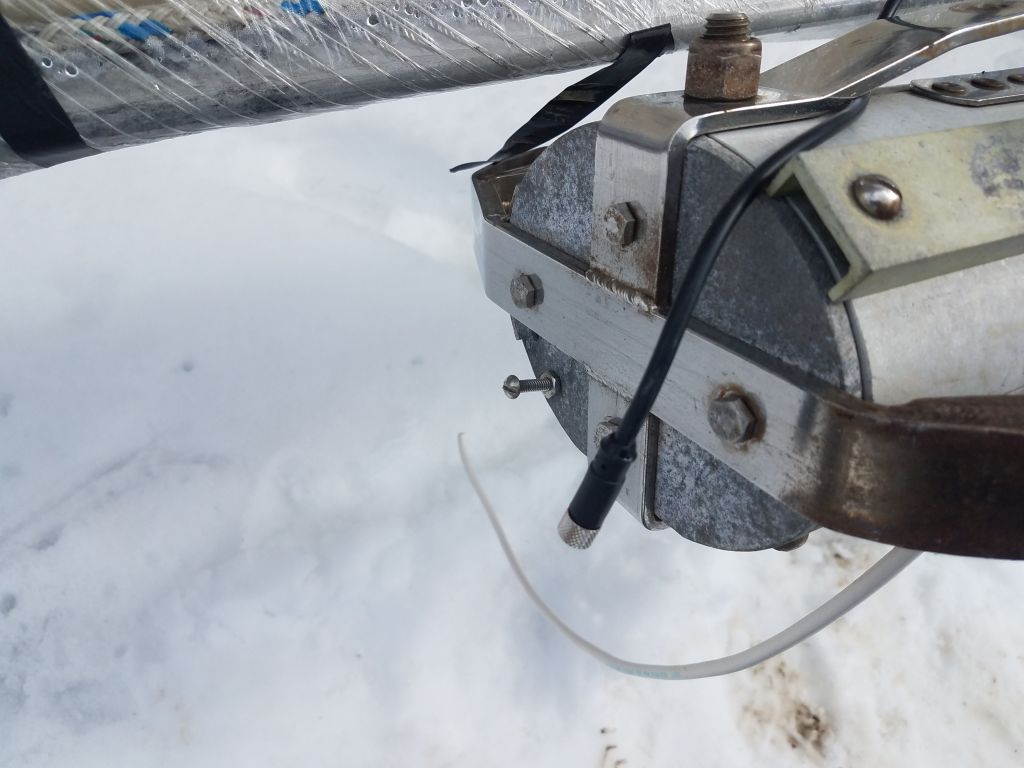
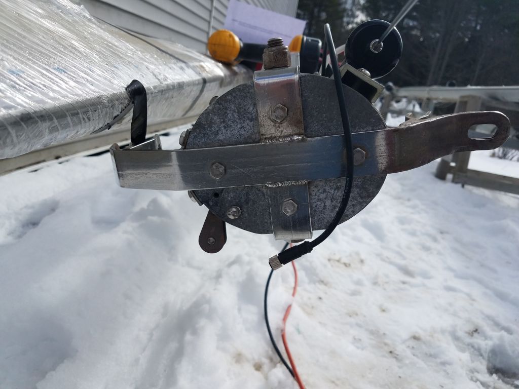
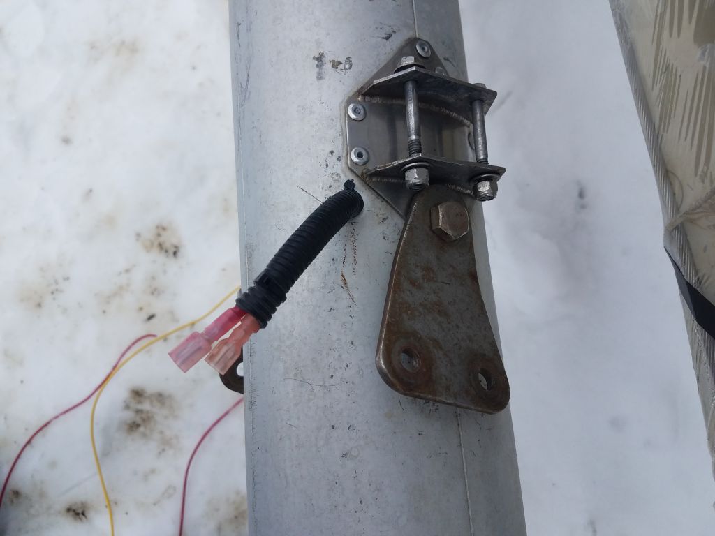
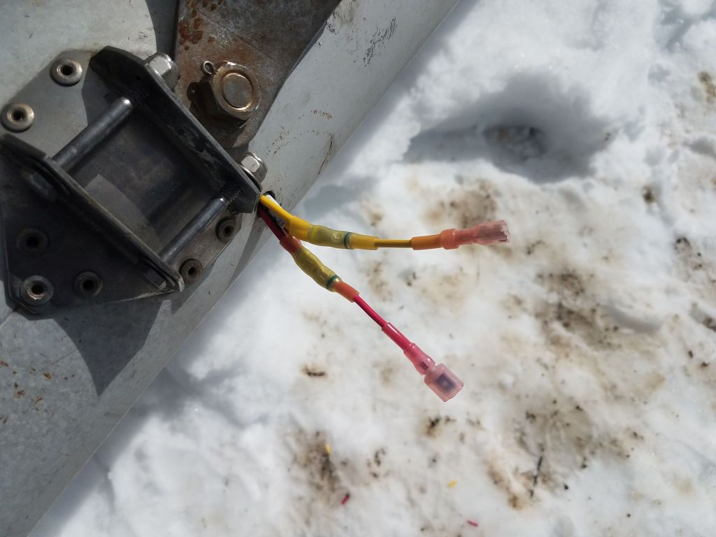
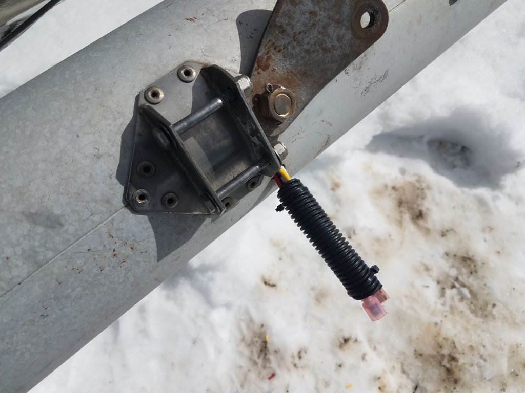
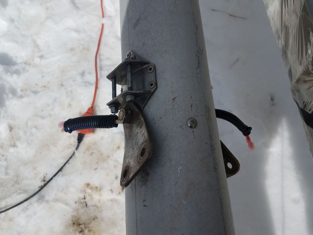
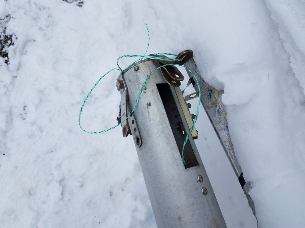
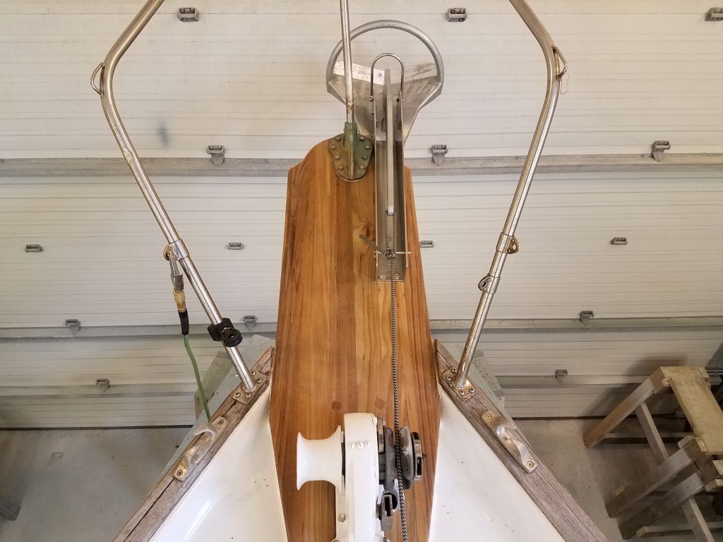
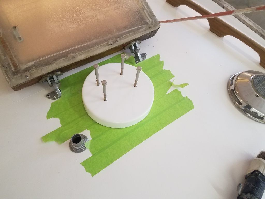
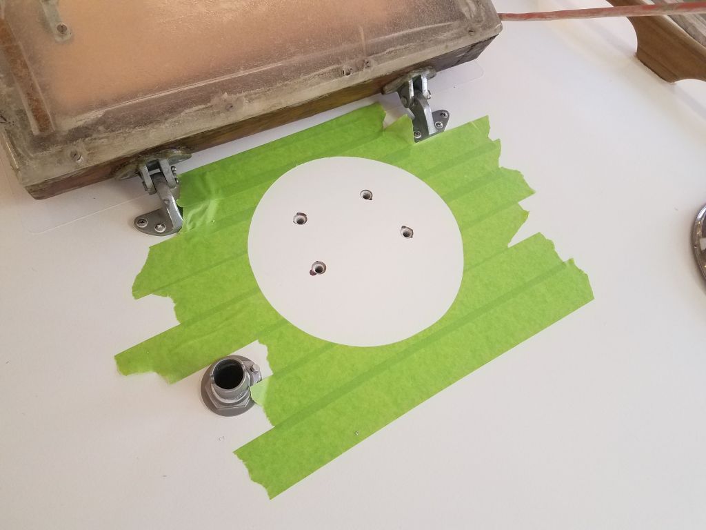
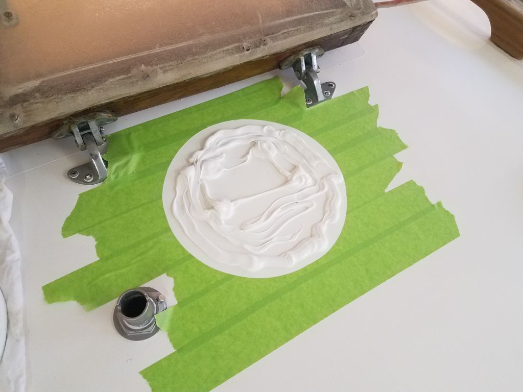
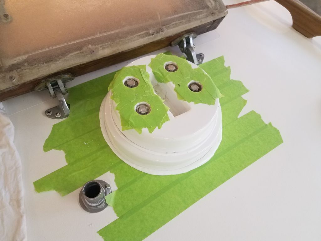
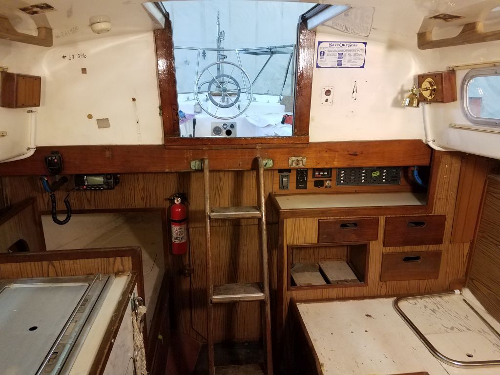
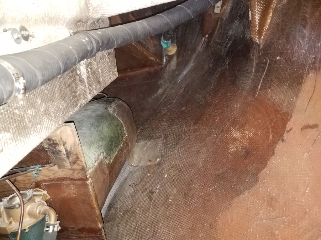
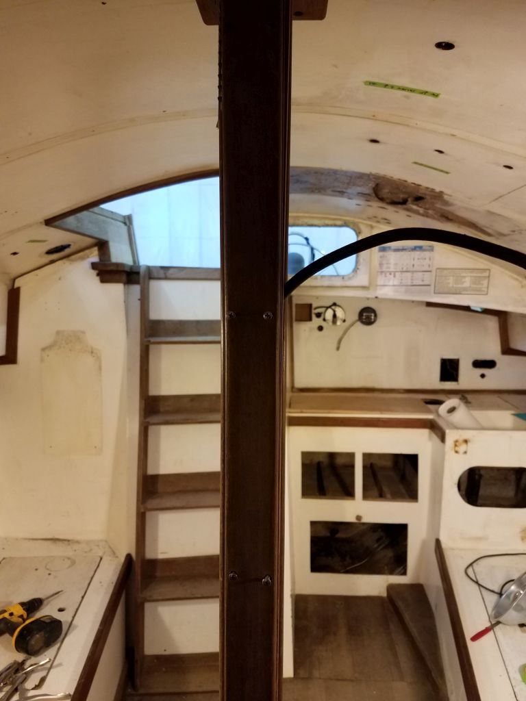
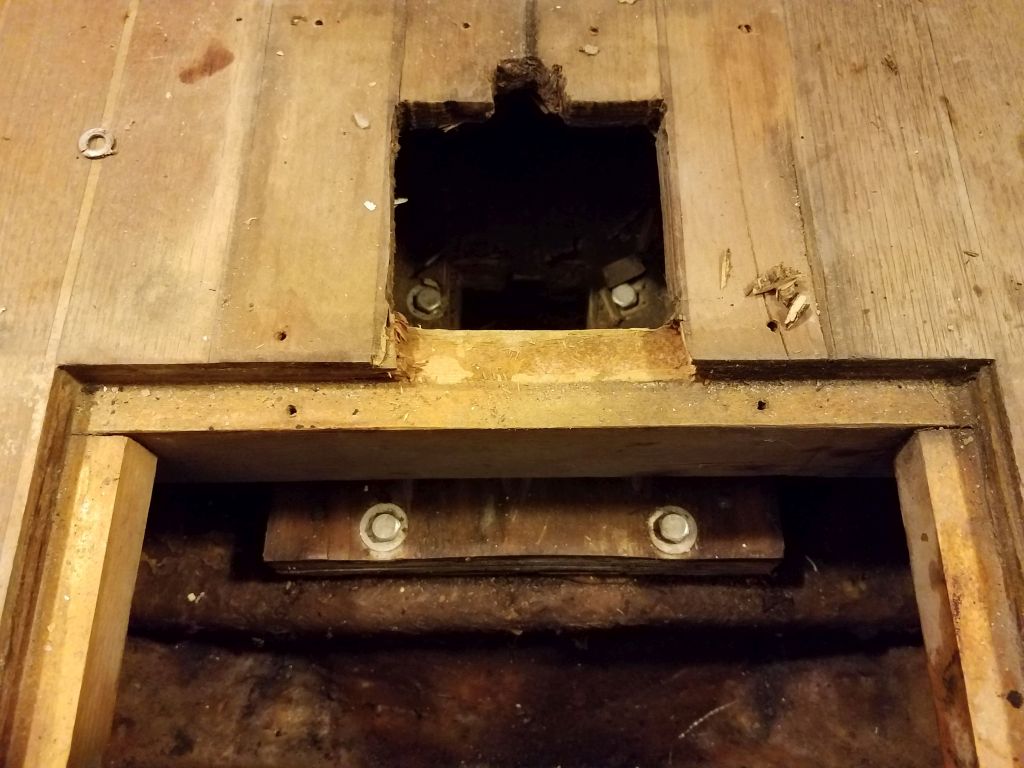
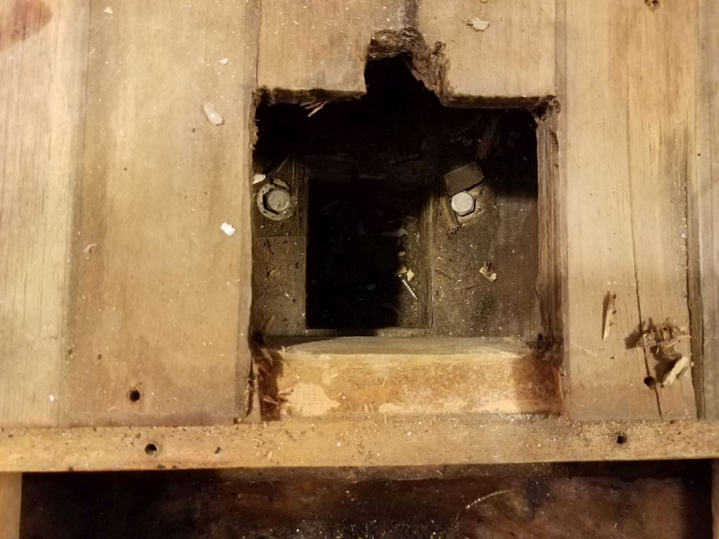
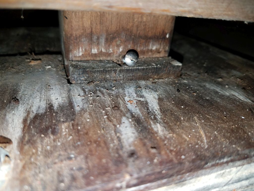
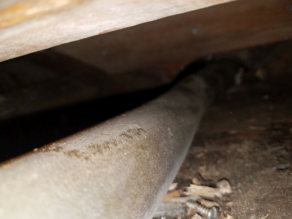
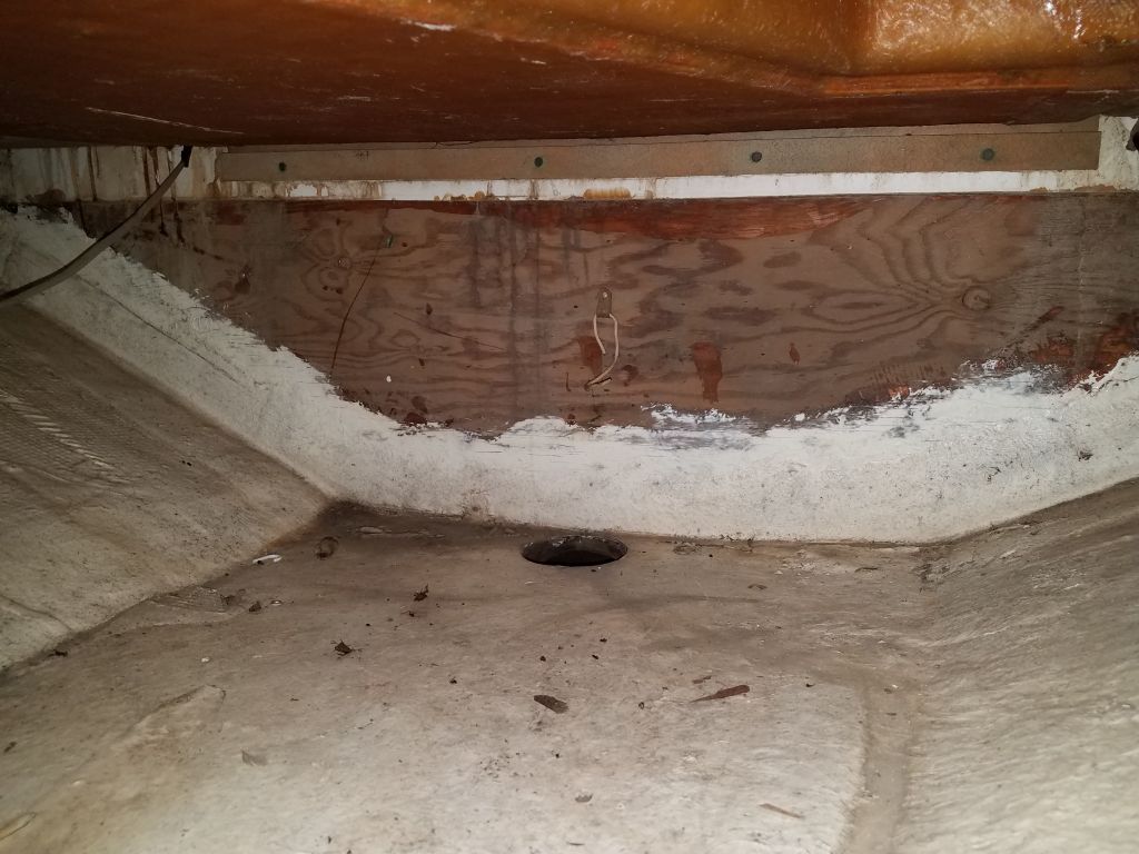
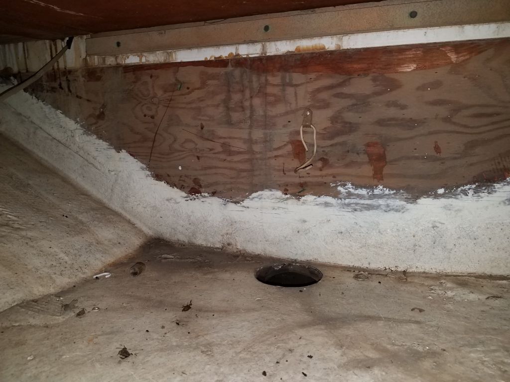
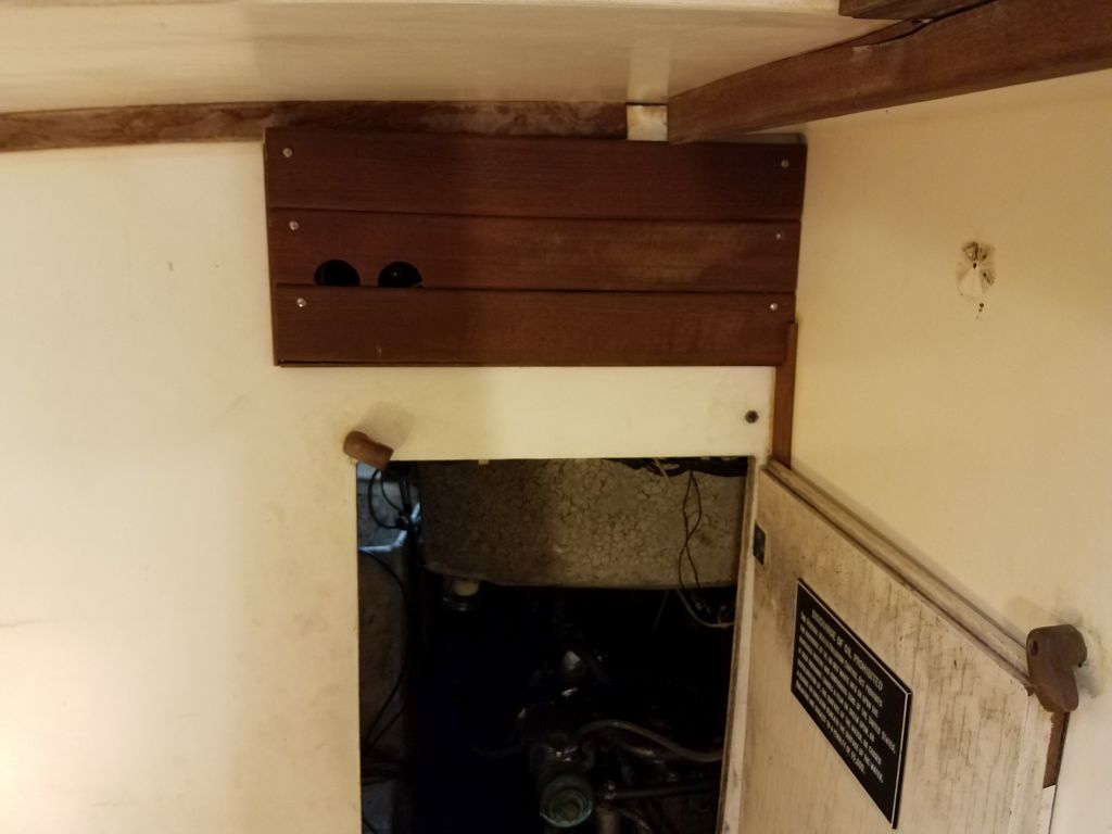
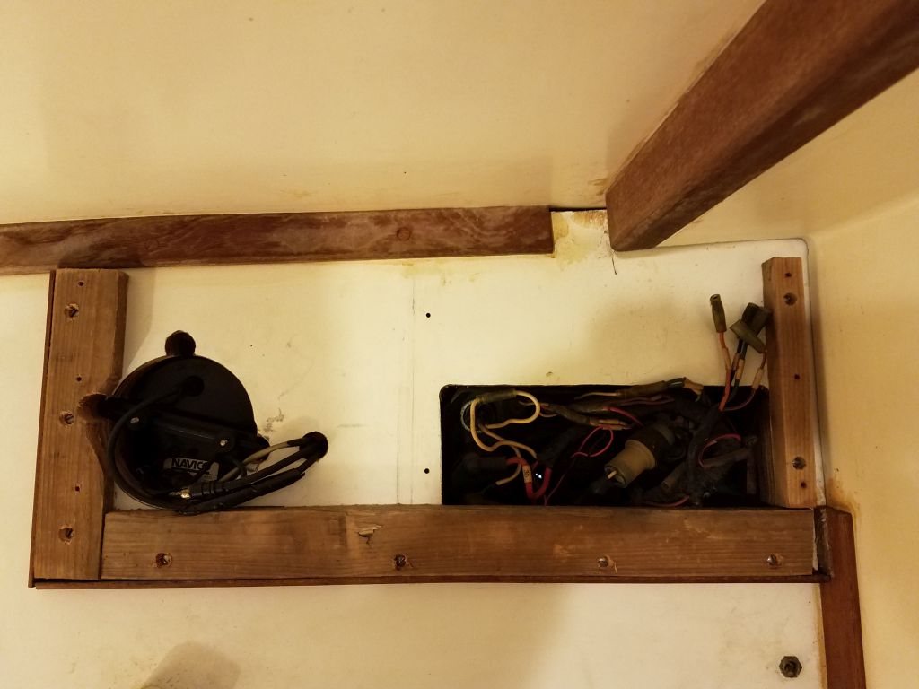
At the aft side, the mast step and compression post were in the way, and so since I thought the mast step would require work anyway, and since the compression post was a major impediment to fore and aft access, I decided to remove it now.  I started by unscrewing a wooden cover on the forward side of the boat, exposing the wiring leading up to deck level and allowing me to pull out the remaining wires.  I thought this might let me pull out the post–note that I’d already unbolted the top portion of the post back when I removed the mast step from the deck in September 2017–but I found there was a little wedge and screw holding the post in place beneath the cabin sole.  After removing that, I could pull out the post and set it aside.  From there, it was easy enough to unscrew the four lags holding the plywood to the fiberglass mast step on the bottom of the hull.  This improved–or at least sort of allowed–access beneath the forwardmost part of the sole so I could see what was going on with the water hose, though the space between the cabin sole beam and the hull itself was just about wrist height and no more.

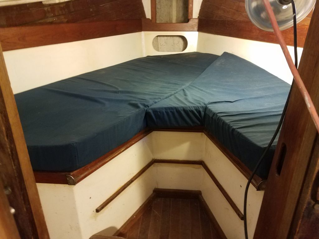
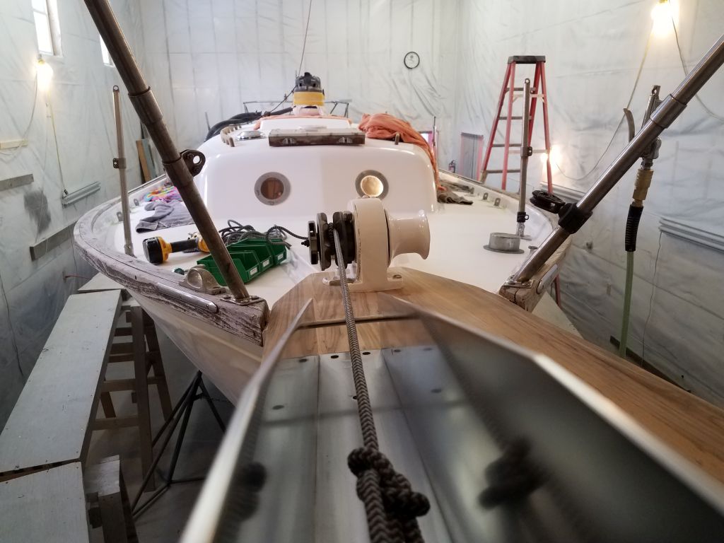
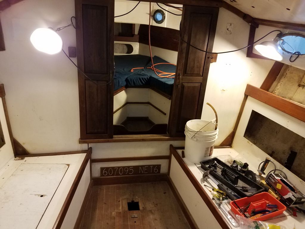
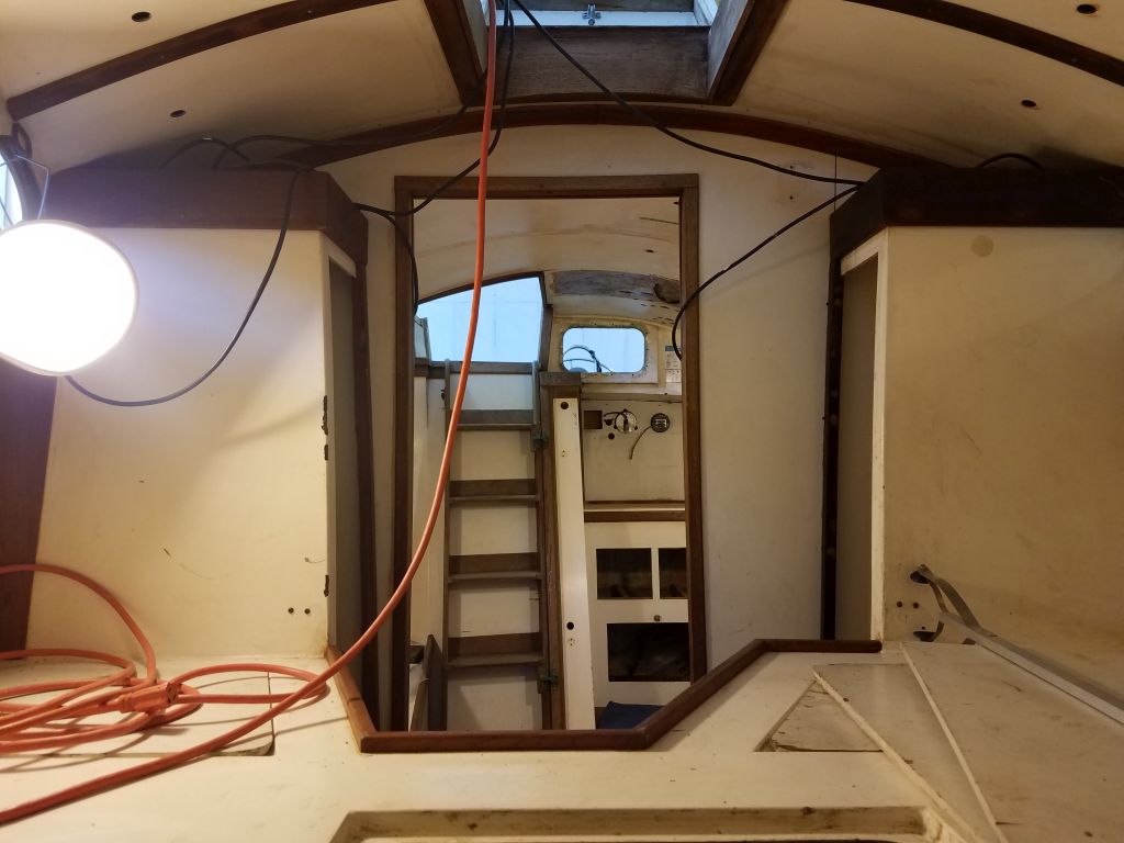
With the post removed, the cabin seemed much more open, and access to the forward cabin was much easier.  Sailboats and their pesky rigging.

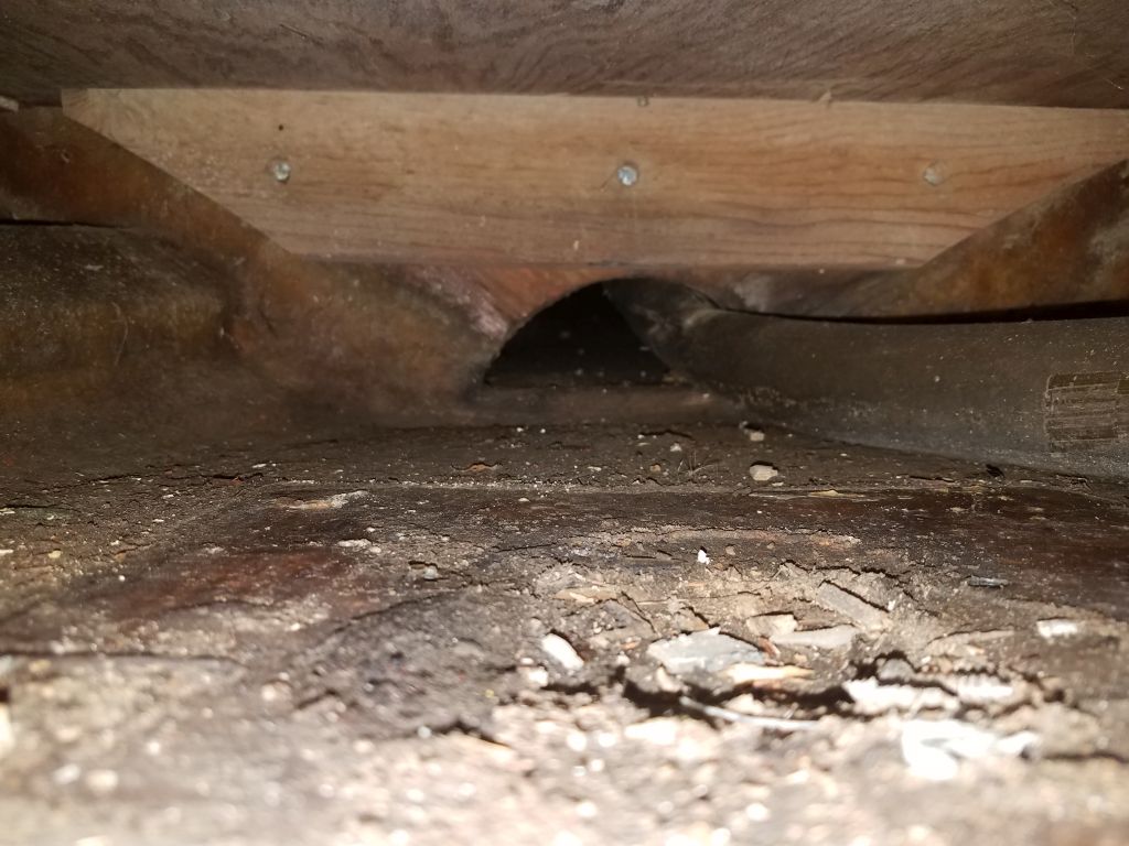
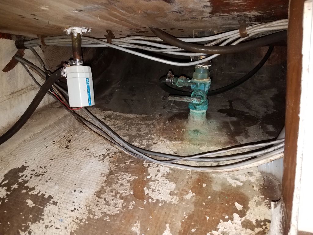
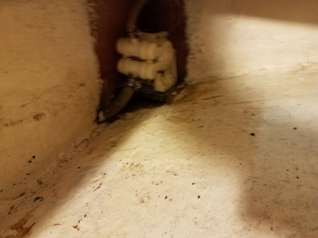
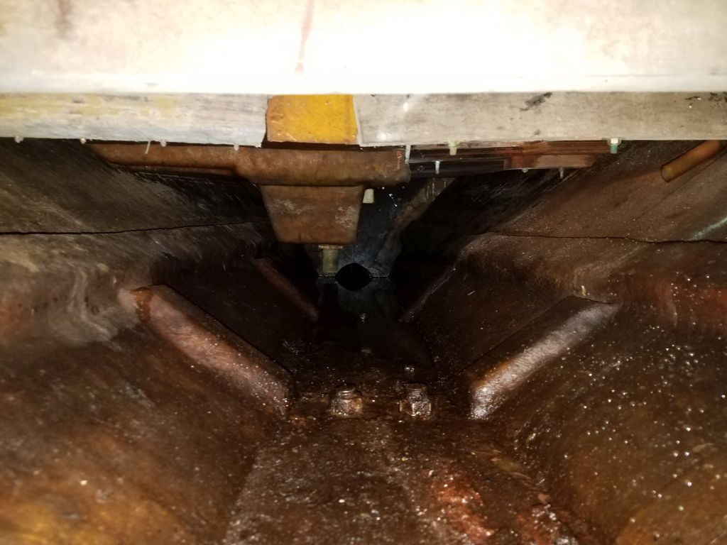
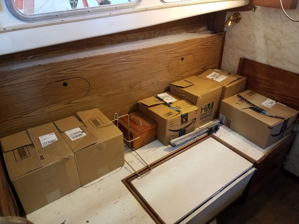
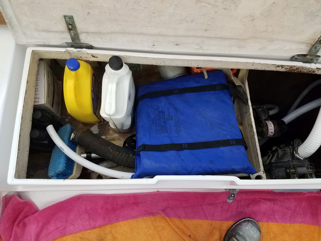
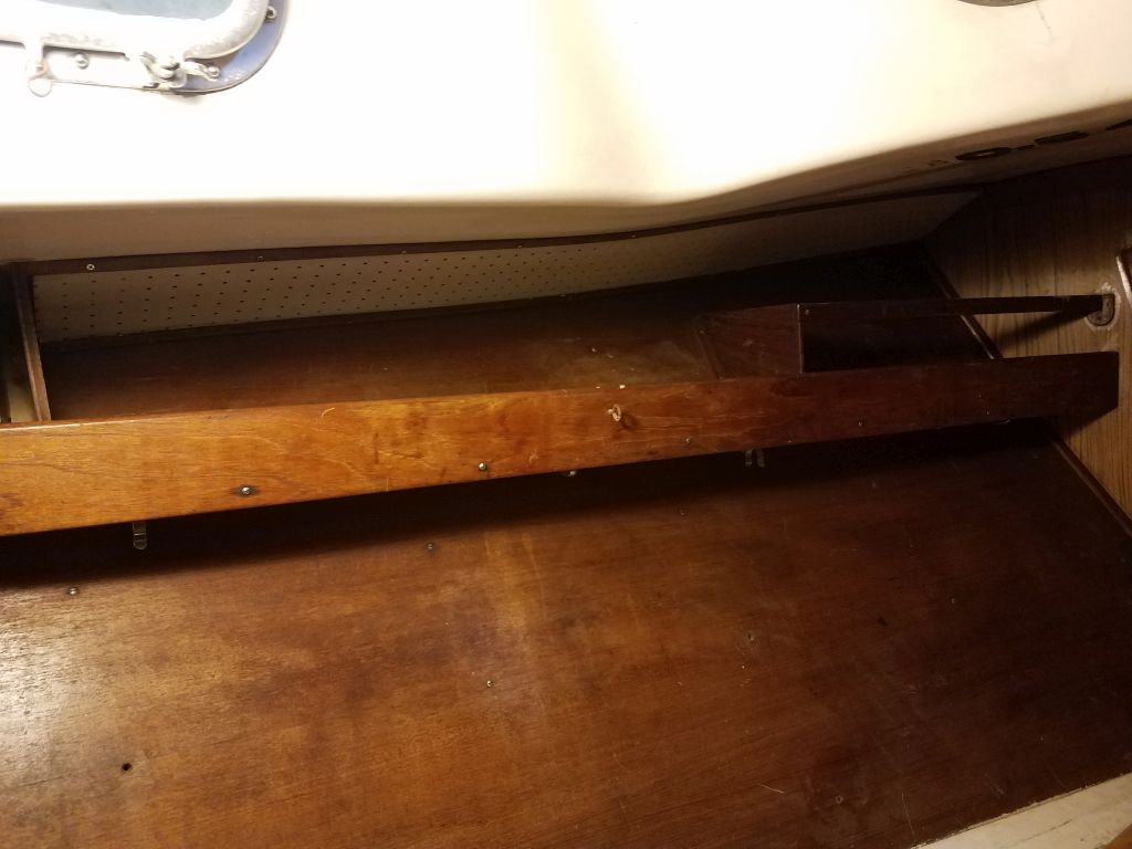
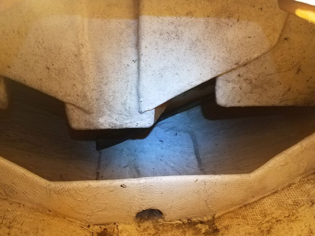
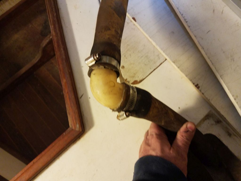
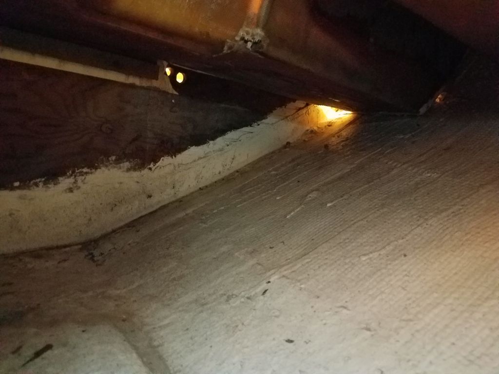
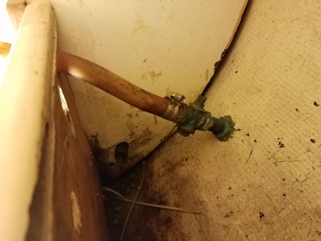
Back to the water hose, now I could see that there was a 90° plumbing elbow just behind the main bulkhead, causing the fill hose to turn to port and up into the locker.  There was not clearance for this to pass through the limber hole in the bulkhead, which was why I couldn’t pull out the hose from the bilge end.    There was no immediate access to the forward side of the bulkhead–it was beneath the forward cabin sole with no hatch–but I found that I could at least see the area if I got down in the large storage area beneath the v-berth.  I couldn’t reach that far back, with the molded protrusions in the way, but now I could see the hose not only had the elbow, but also dipped through a smallish opening, which made it difficult to pull from the forward side too.  Eventually I got the hose out, grabbing it with a long-reach tool that I keep on hand for these situations.

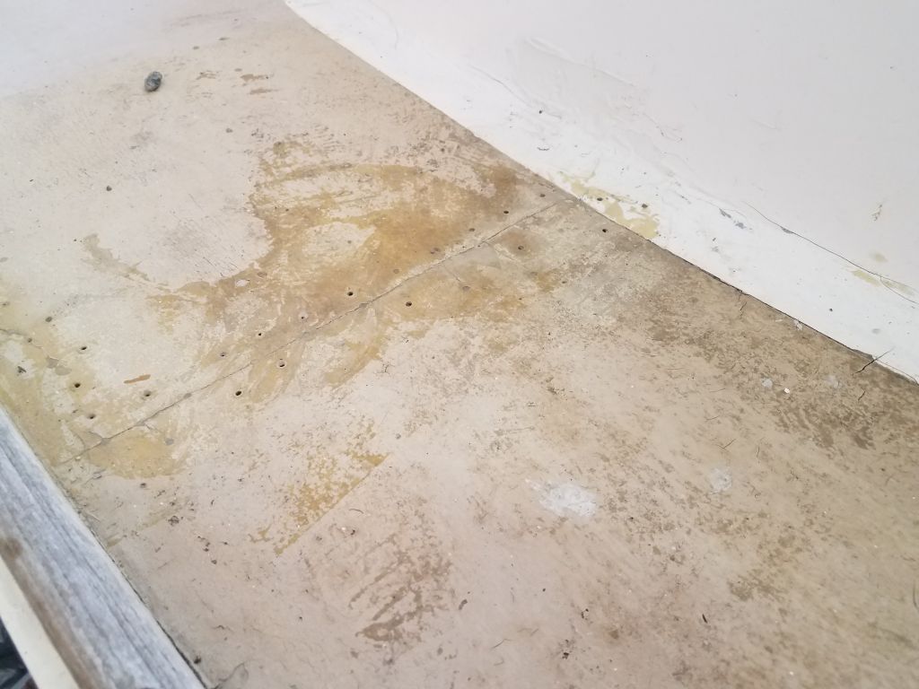
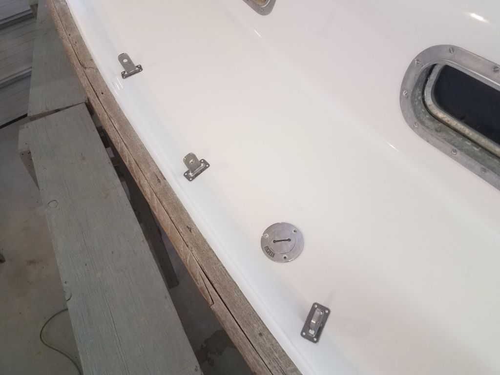
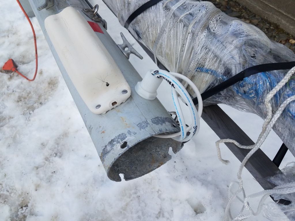
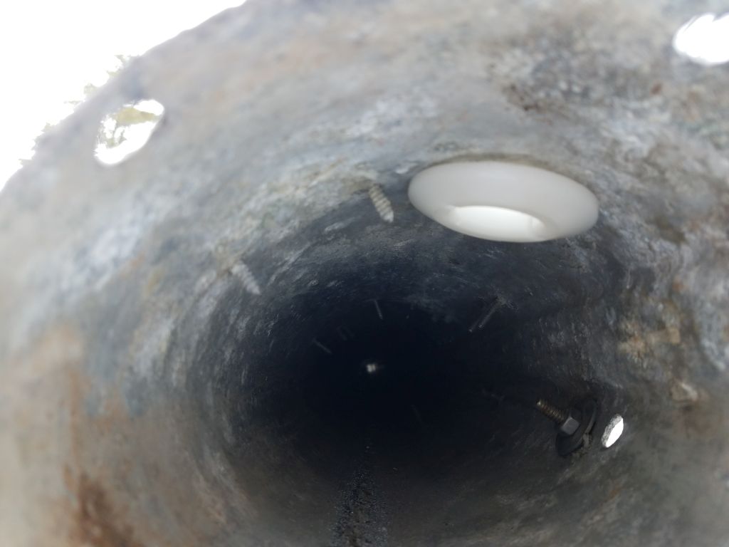
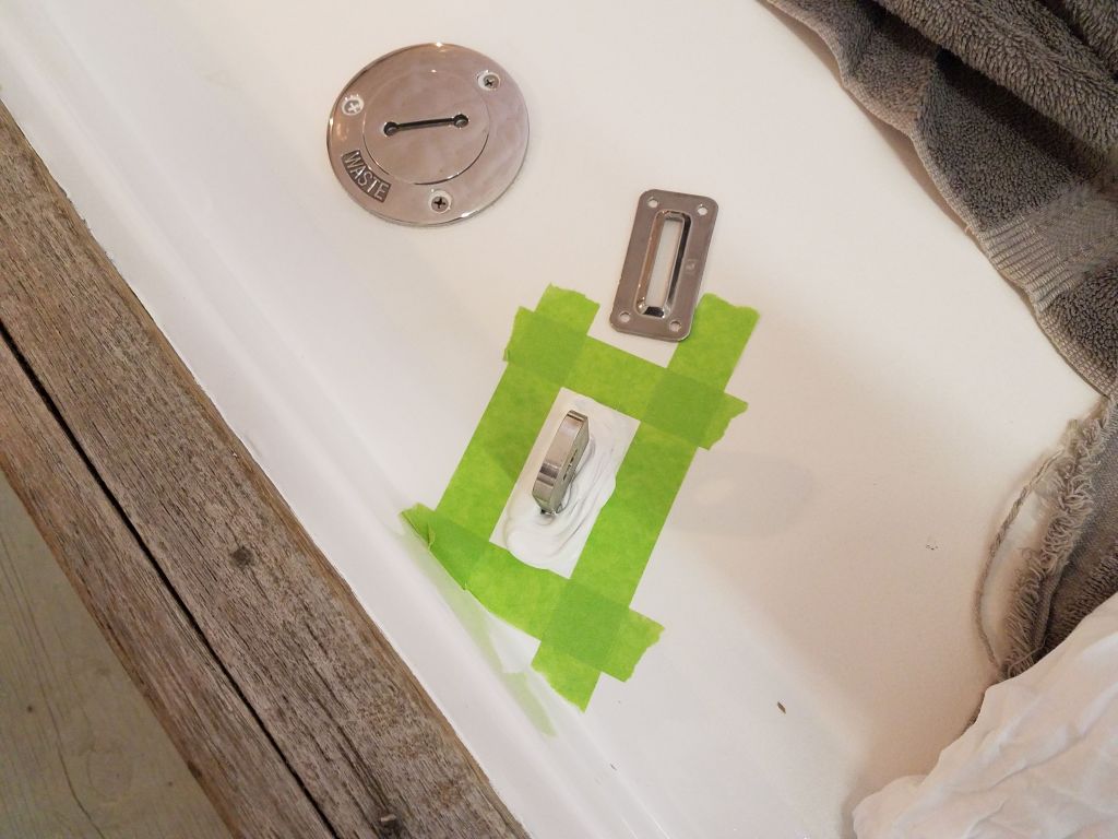
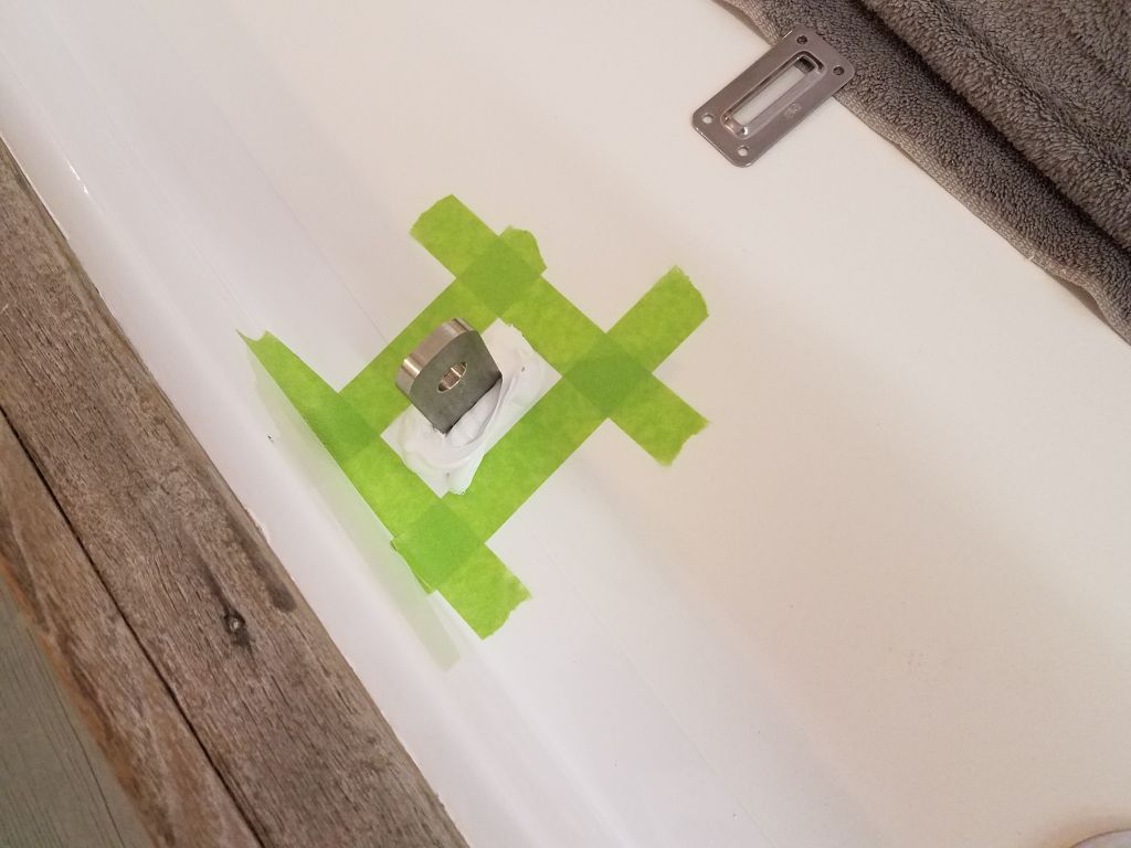
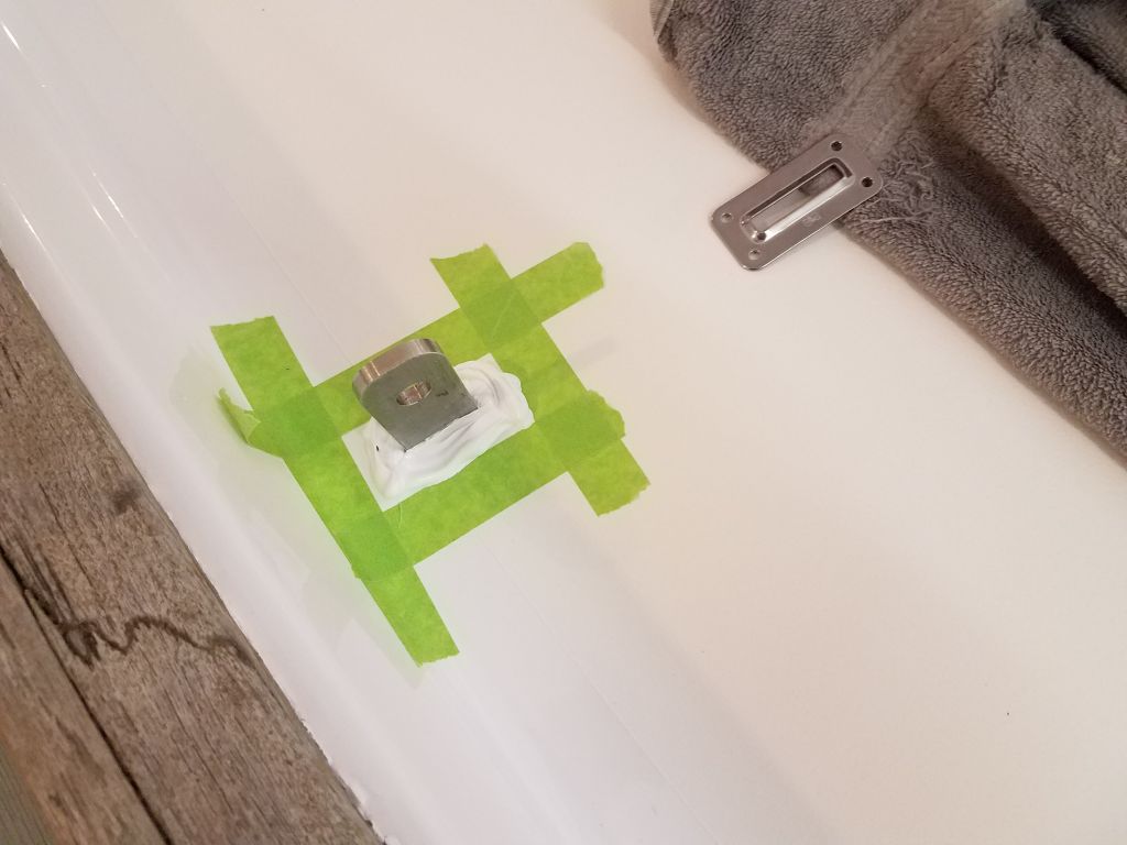
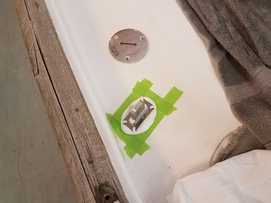
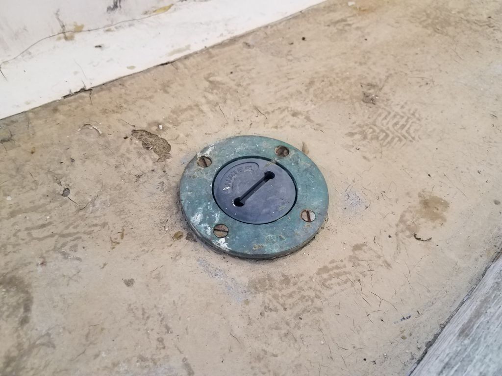
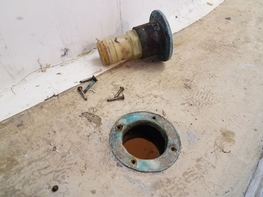
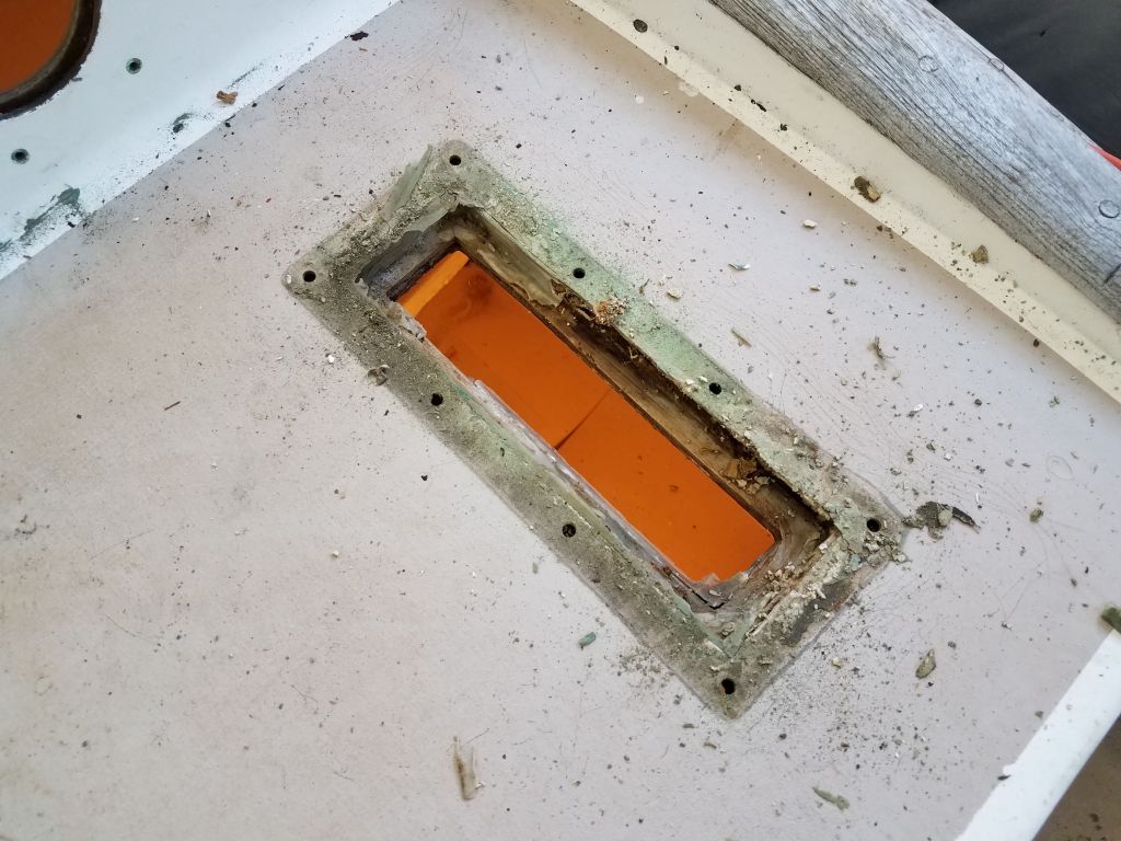
With the disgusting hose out of the way, I went on deck to remove the deck fill itself, which was easy.  This revealed some wet plywood core around the opening; it appeared this sidedeck had been repaired in the past (poorly), since the overall core material in this boat is balsa, but I’d be into this part of the project in the near future anyway.

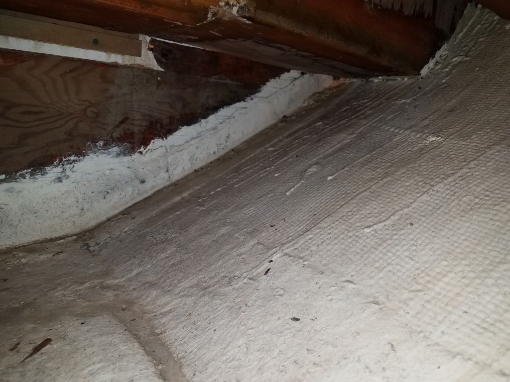
My access to the water hose and forward lockers also gave me a chance to check out the tabbing securing the main bulkhead in place.  Like most production boats with deck liners, the bulkheads in this boat were tabbed only to the hull, not to the deck above, but at least what I could see of the tabbing for now looked sound and had proven apparently sufficient over the 40-year life of the boat so far.

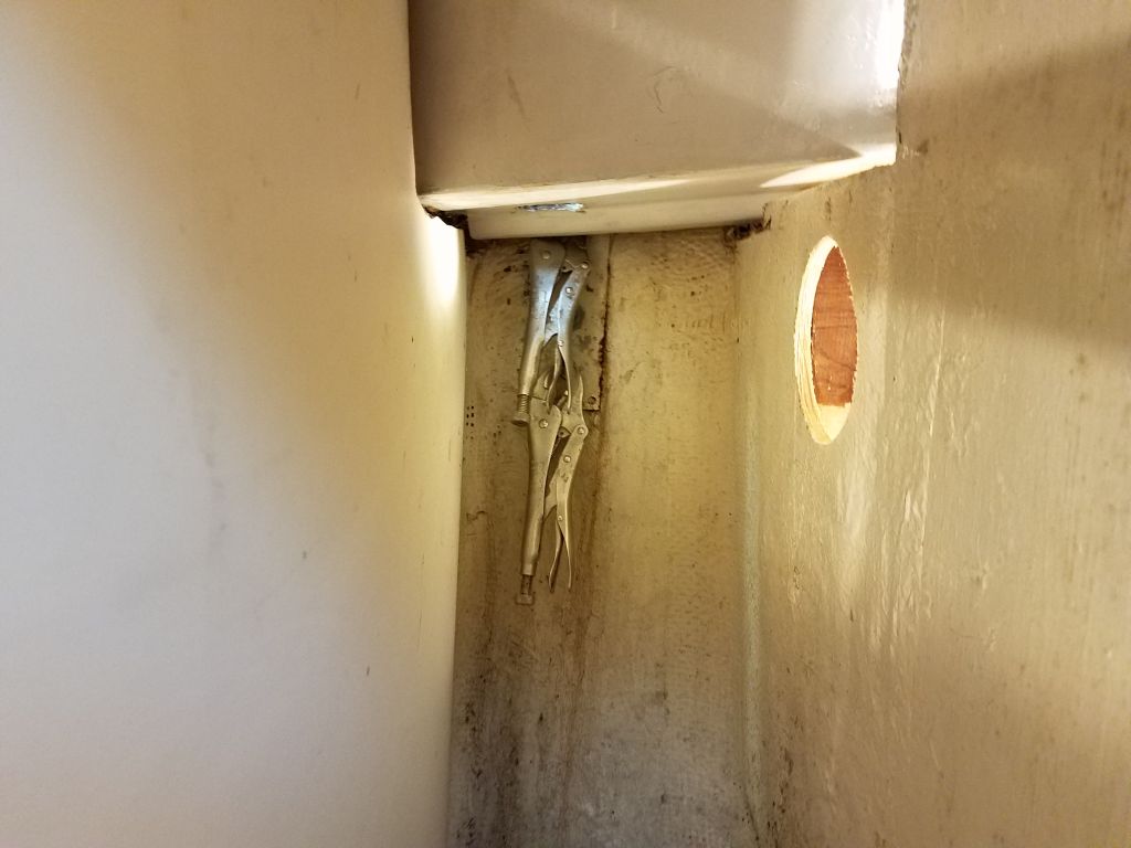
So all this was more or less a precursor to the continuing removal of the chainplates.  With access clear, I found I could just barely reach, as necessary, the nuts on the starboard side, either with a long socket extension and, where needed, to clamp on some locking pliers on the bolts that spun beneath the nut.  Reinstallation later would be its own issue, but for now at least the removal was complete.  Again, on the starboard side the molded deck liner did not impede access–visually or otherwise–to the uppermost bolt on the chainplate.

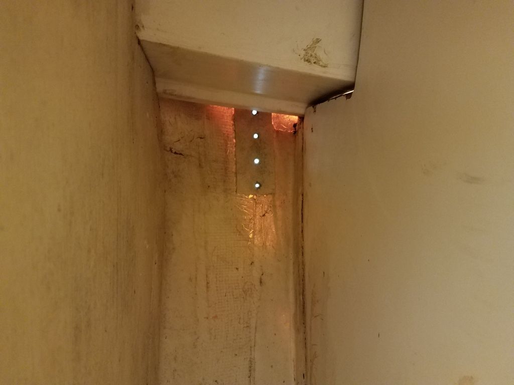
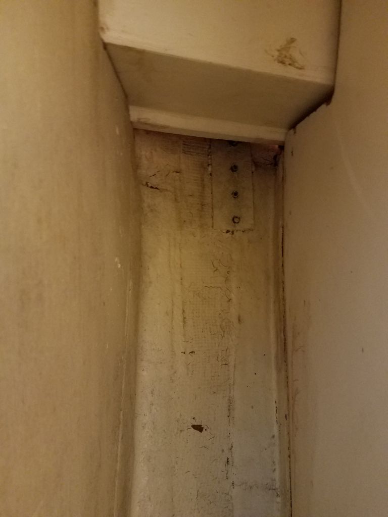
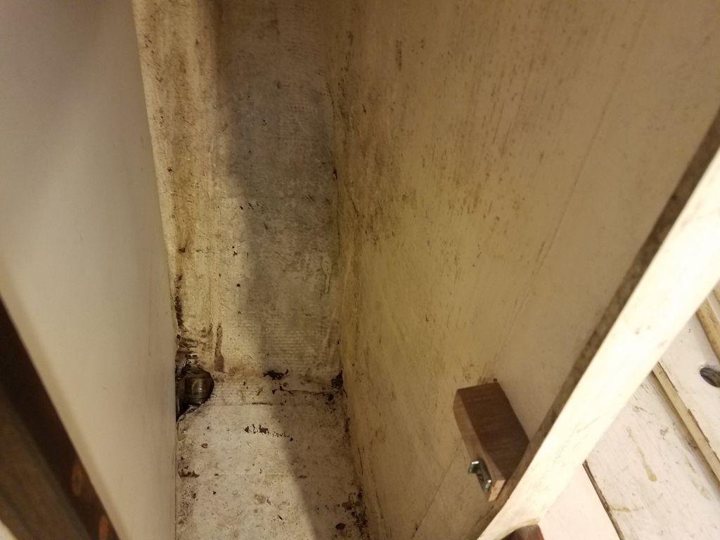
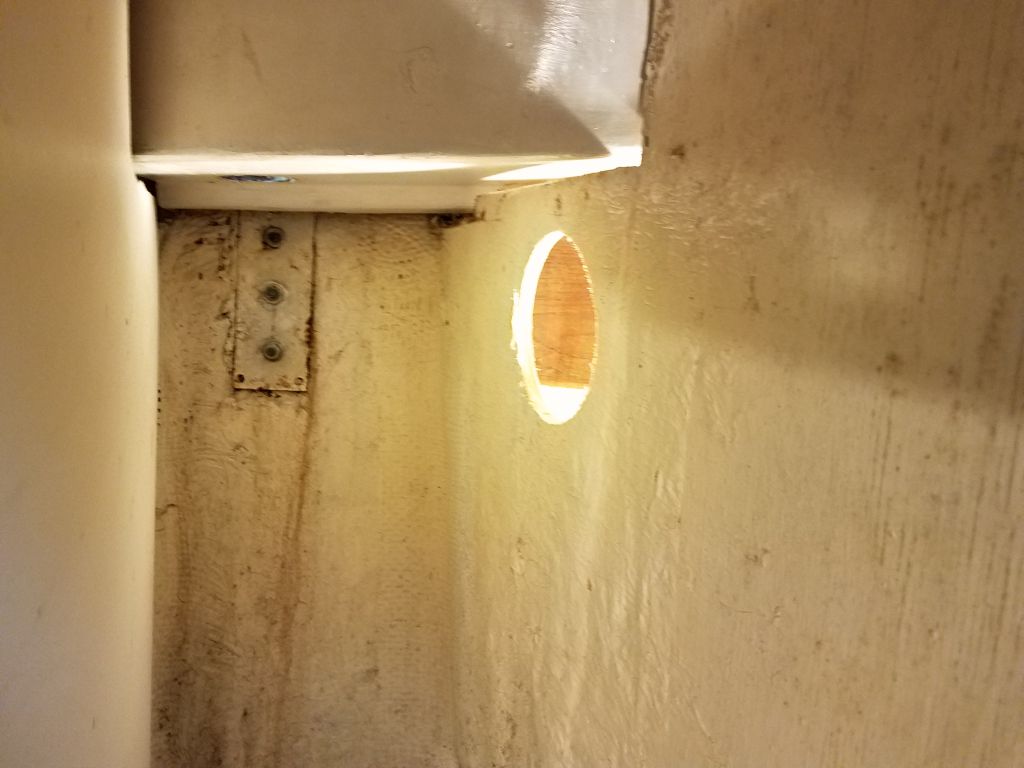
On the port side, however, the way the liner sat meant that I couldn’t see the uppermost bolt, and this made accessing it nearly impossible.  Plus it seemed this locker was juuust enough deeper than its counterpart that I couldn’t adequately reach the nuts–or maybe it’s because my left arm, which was how I had to access this side, was shorter than my right.  In any event, I didn’t see how I could remove this chainplate without creating an access hole in the forward side of the locker molding.  This led to a long and tangential process.

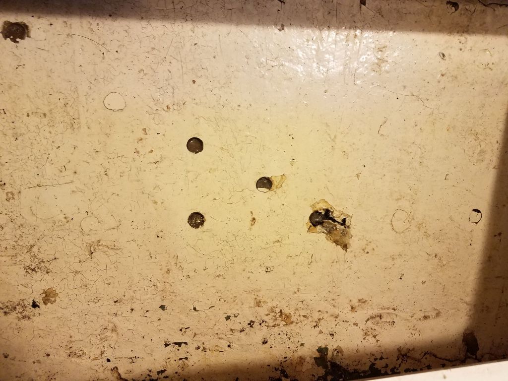
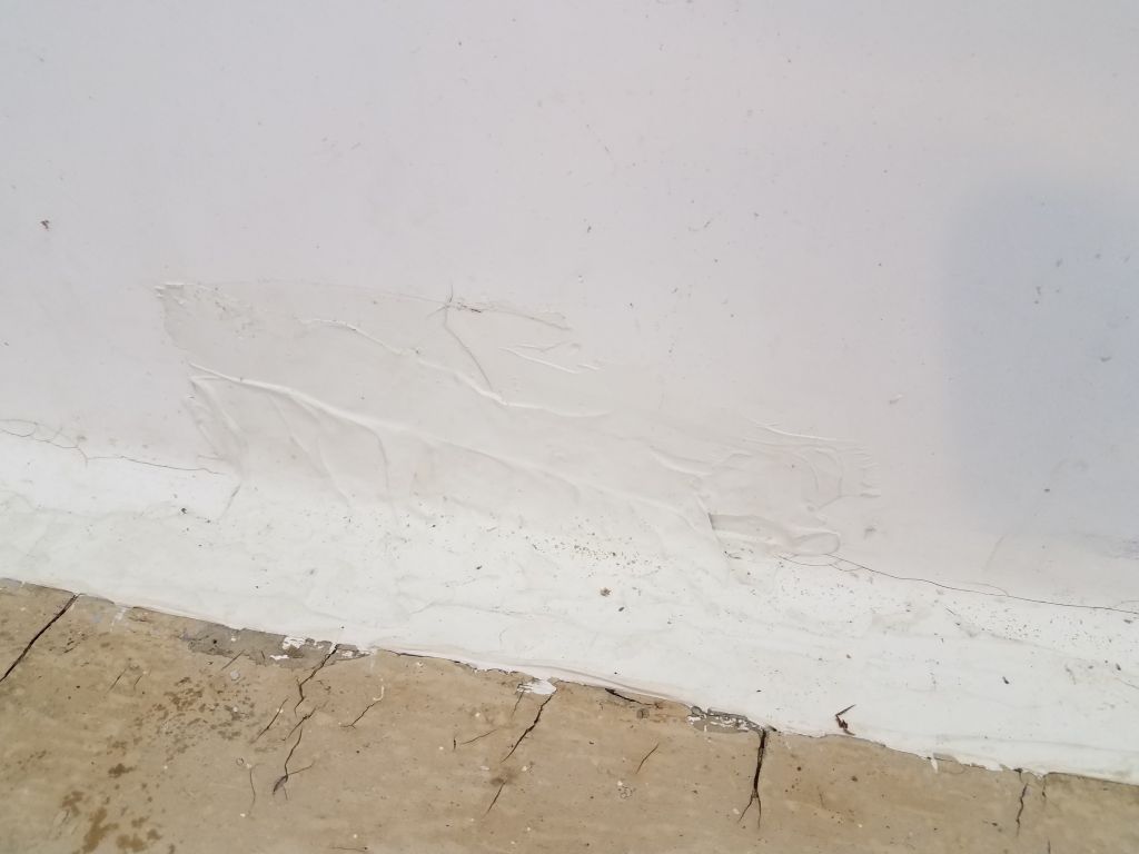
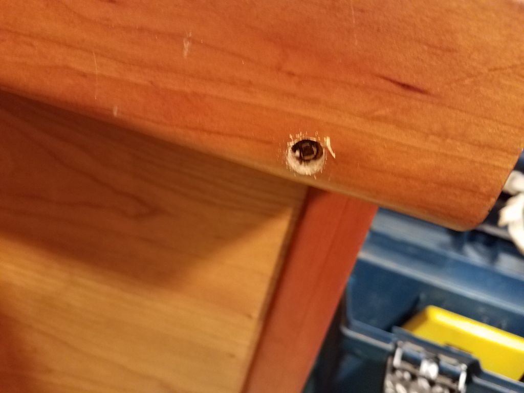
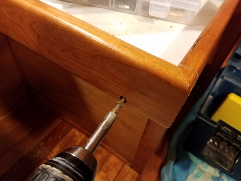
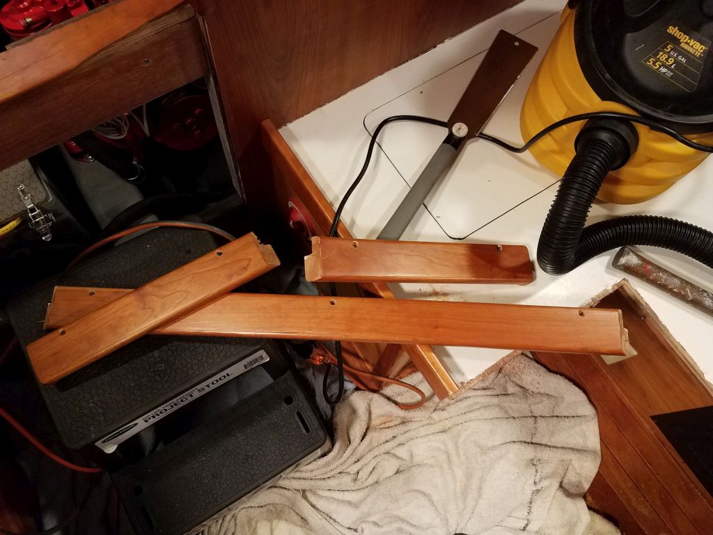
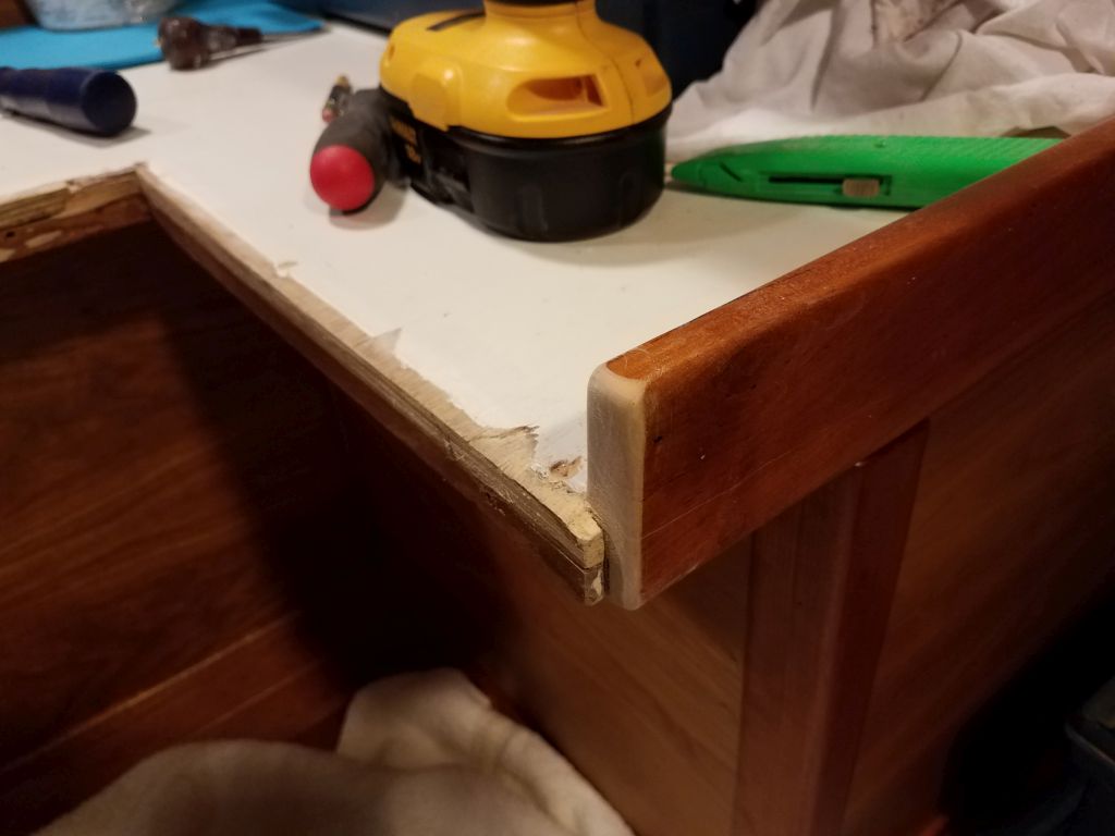
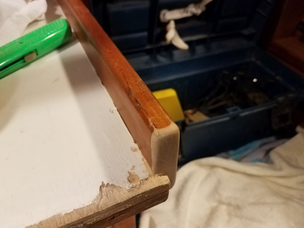
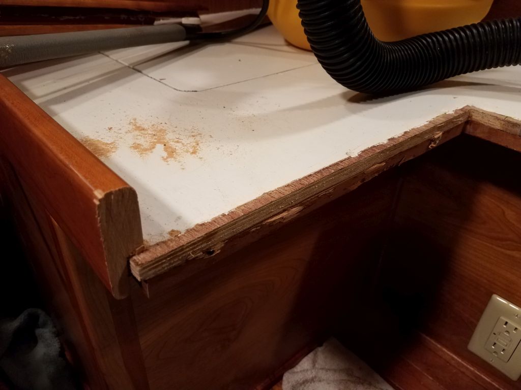
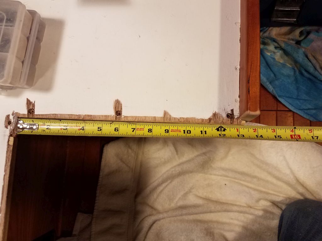
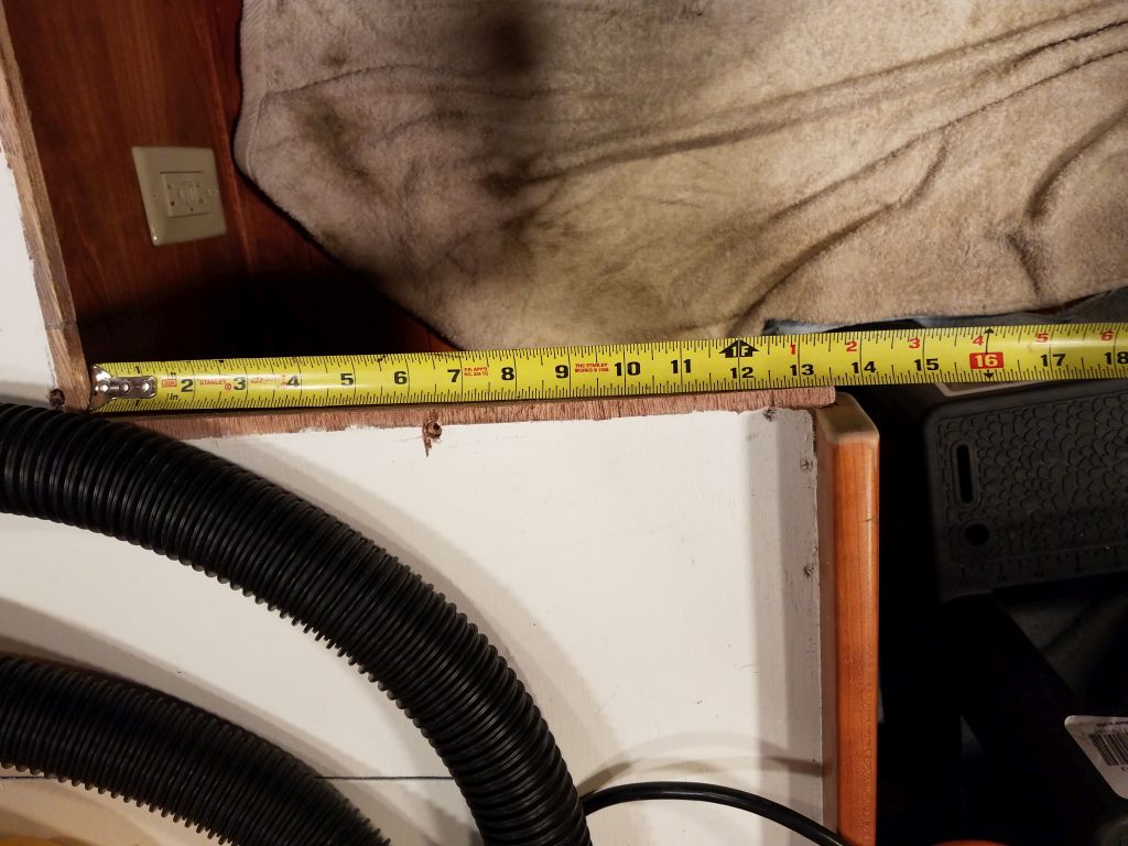
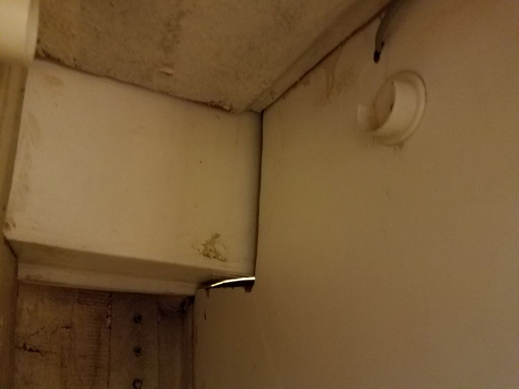
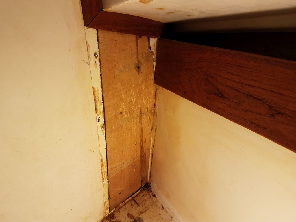
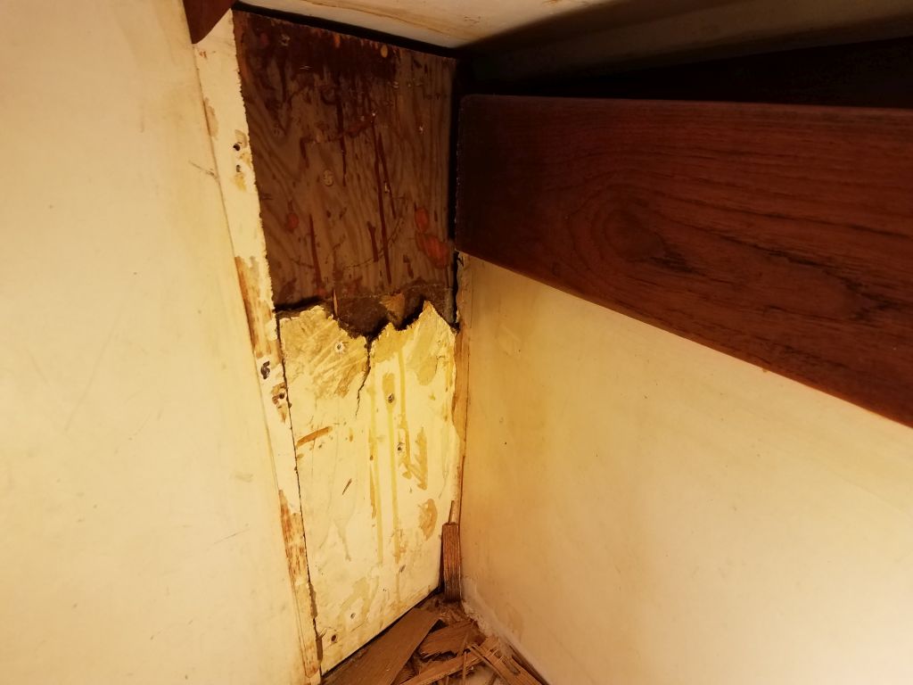
On both sides, in addition to the regular bulkhead trim pieces, there was a larger trim piece extending down from the edge of the cabin trunk to the berth top.  I thought that I could remove that trim, then cut an access hole in the front of the locker behind it, making for a relatively simple and easily-hidden access hole.  The teak trim was just 1/4″ thick, but was secured with bunged screws.  I drilled out the bungs, exposing the screws, but soon found that the trim was also secured with silicone sealant from behind, and in short order I decided that not only could I not save it, it wasn’t worth saving, so I pried off the trim to expose–I thought (if briefly)–the molded panel behind.

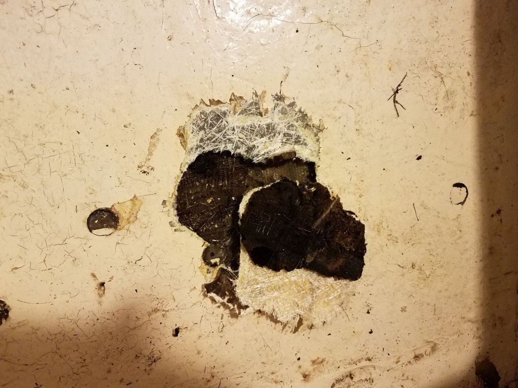
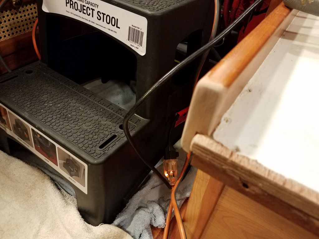
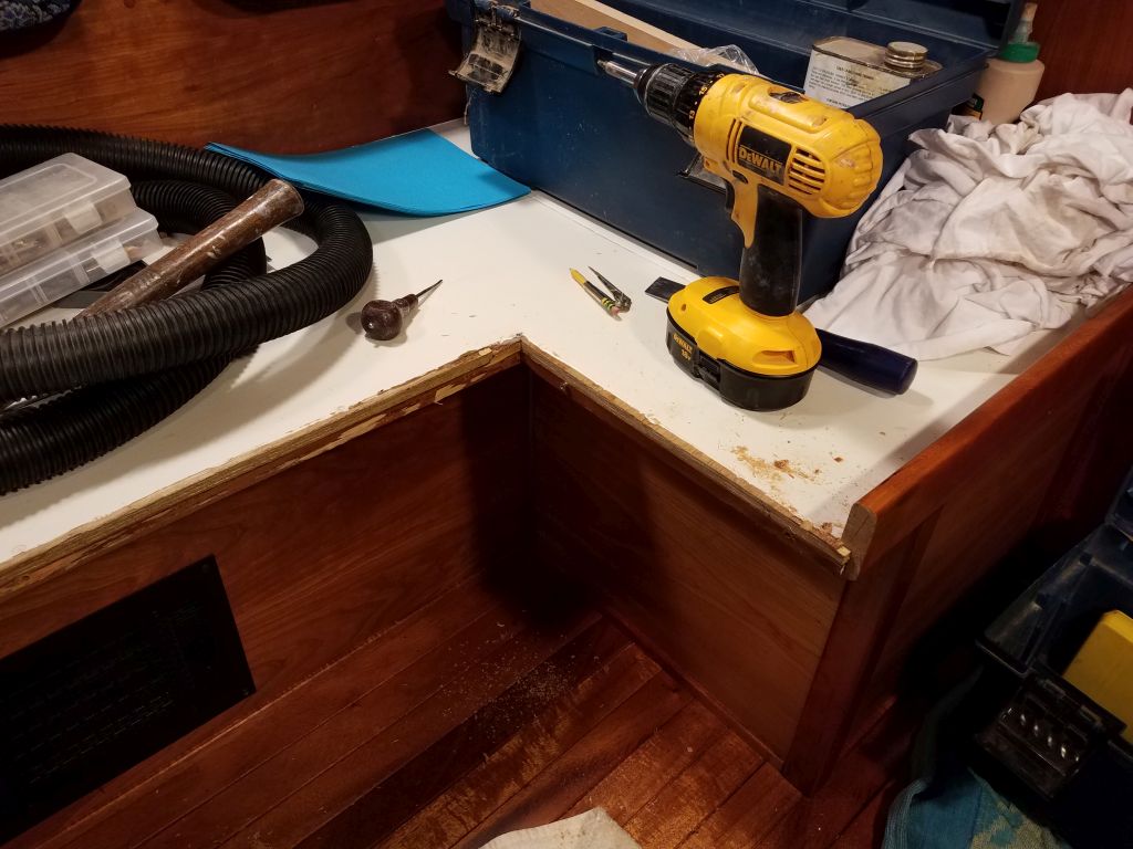
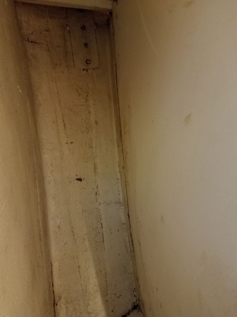
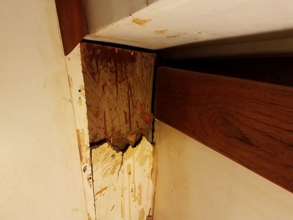
What I found instead was a mess of cheap and delaminating plywood covering an ugly rough edge in the molded panel, with an auxiliary plywood panel beneath it all.  This part was glassed from inside the locker, and while I’d noticed the glasswork before (it was painted to match), I’d not thought much of it.  Of course I had no idea what had happened here, but the pieces were all falling into place and suggesting some accident that had damaged the deck on this side, leading to the myriad repairs to the toerail and deck edge and the hull as seen from the outside.

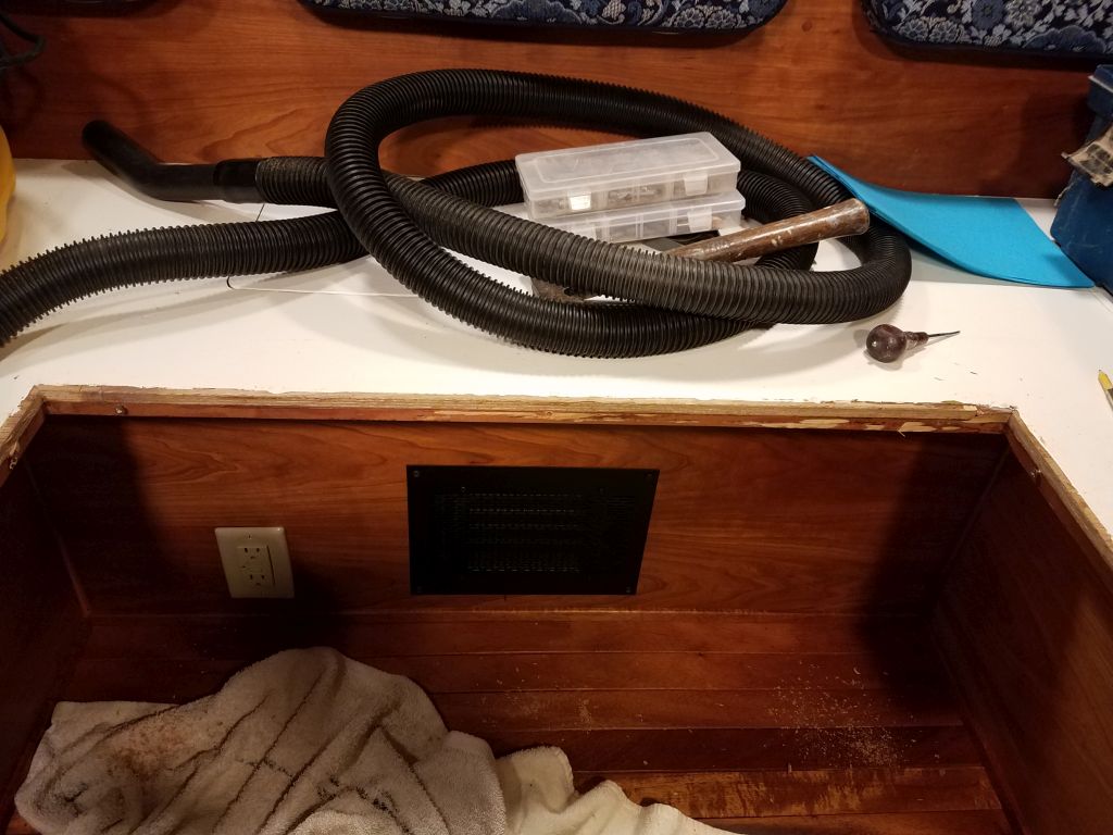
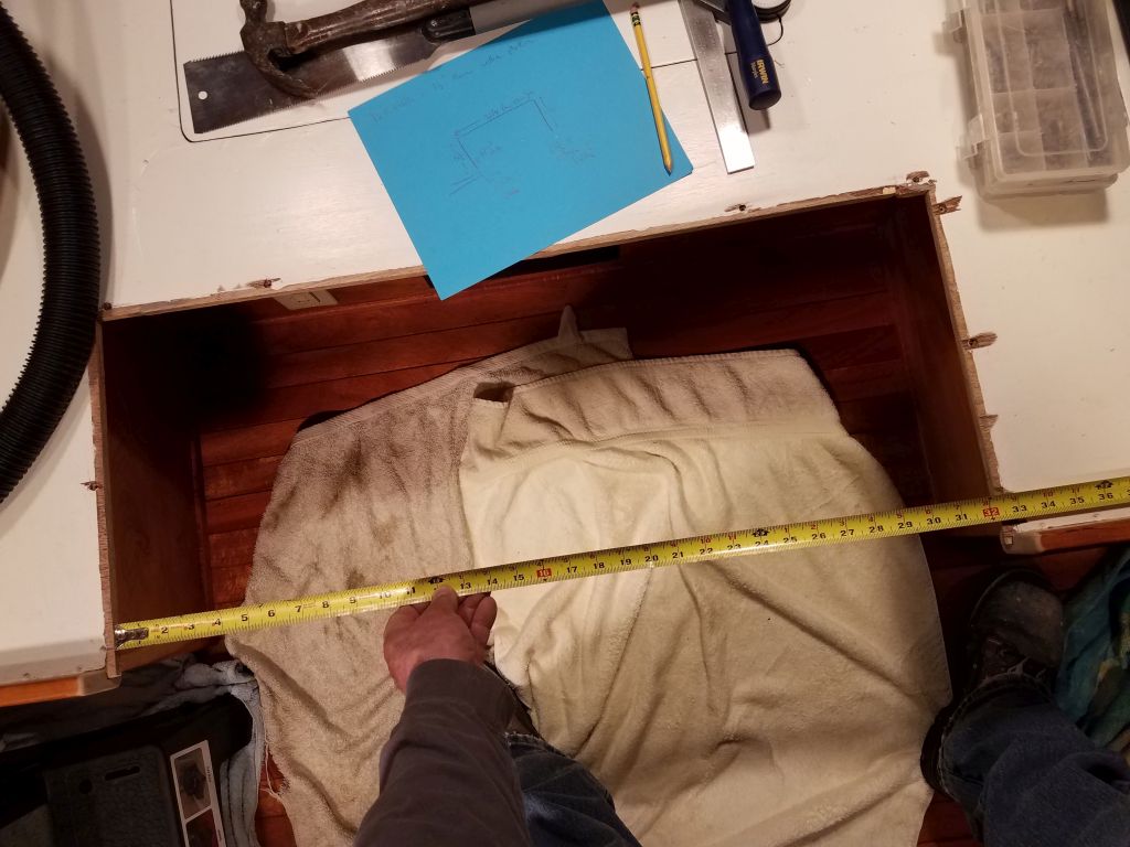
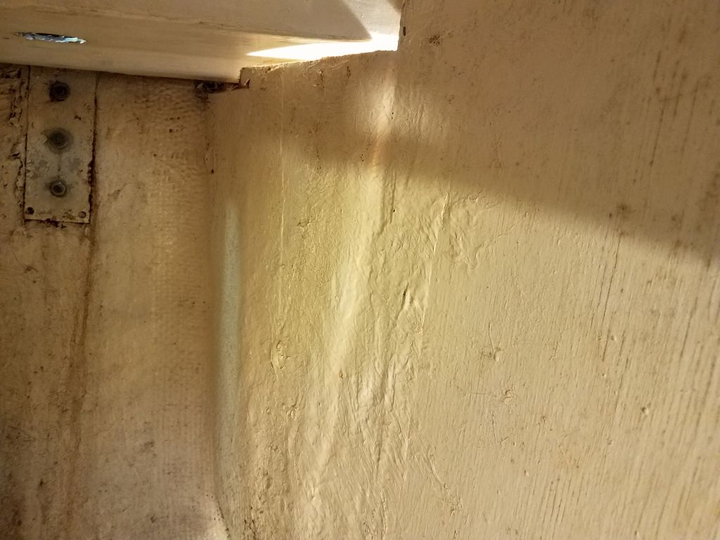
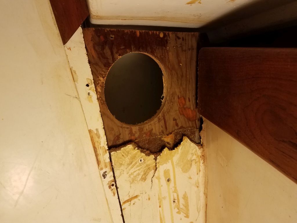
Whatever the case, it was what it was, and better repairs were on the way soon.  The liner and locker area itself were not inherently structural in any event, so for now I just removed the last of the plywood detritus and cut my access hole–finally–in the forward part of the locker, which allowed me to better access the chainplate and remove it.

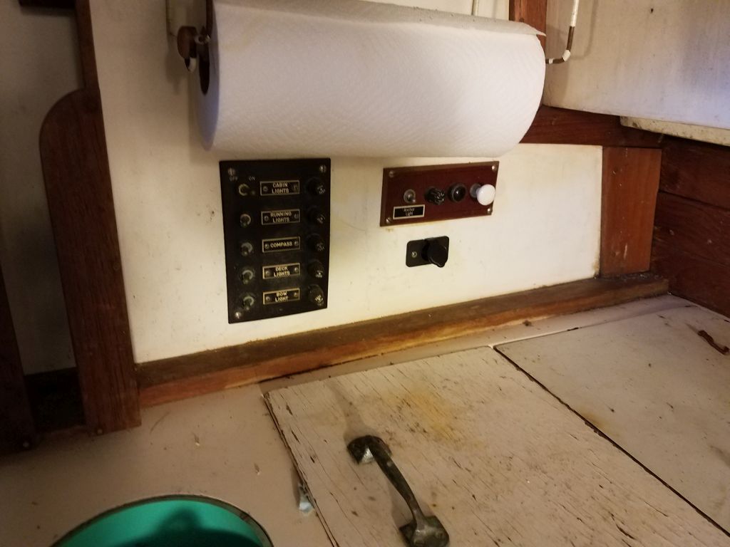
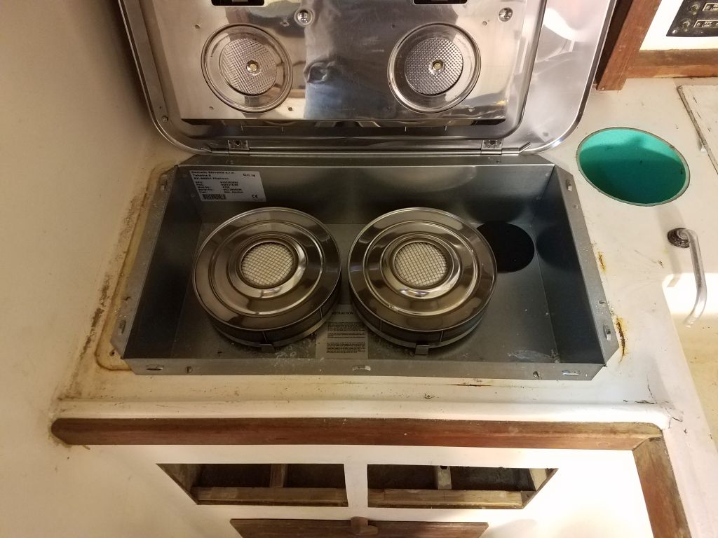
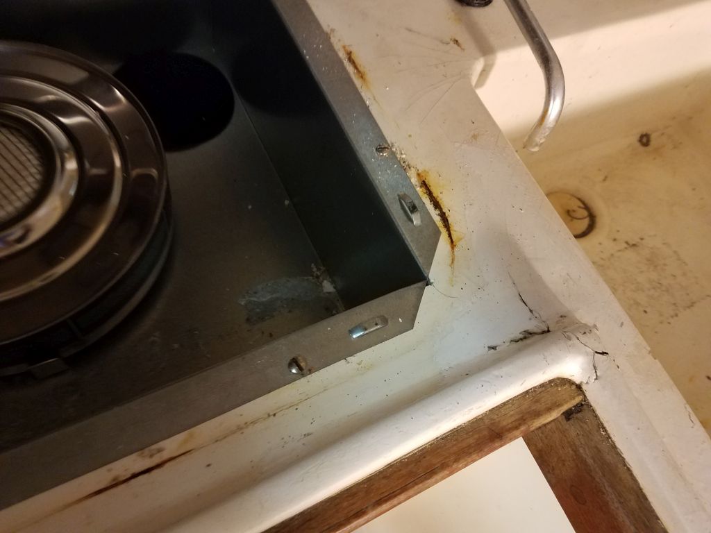
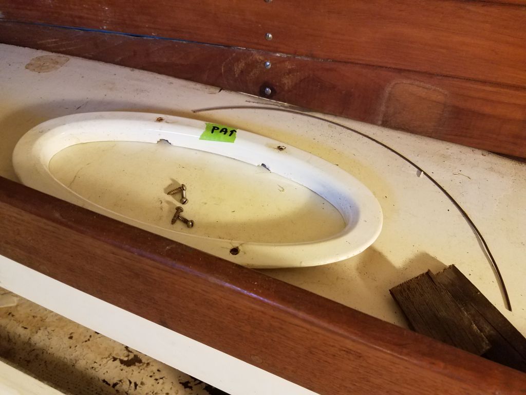
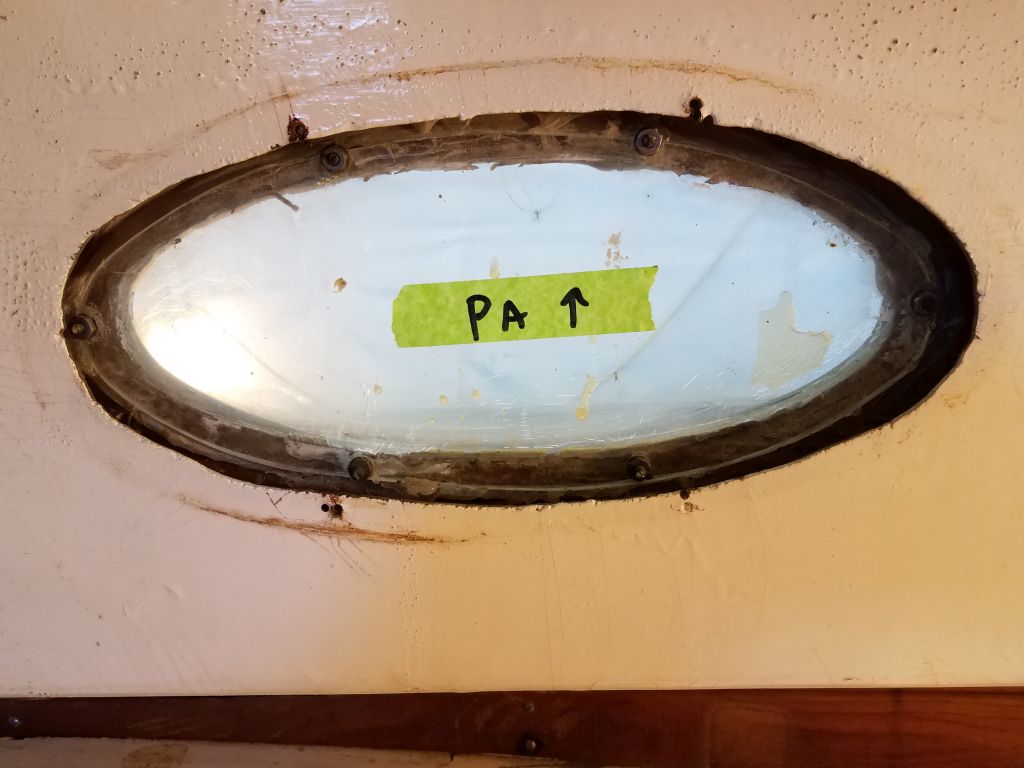
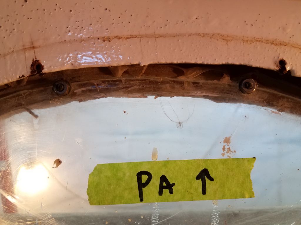
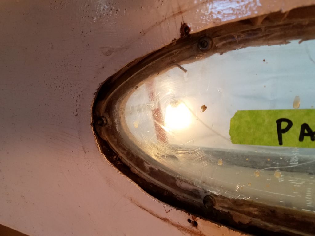
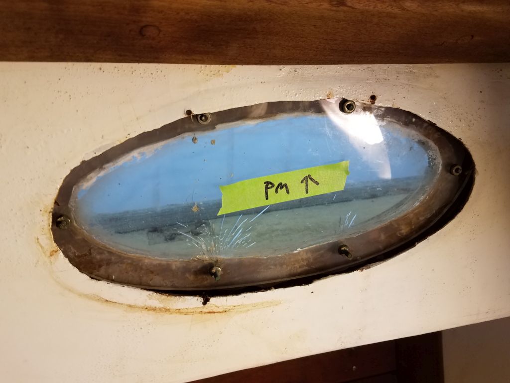
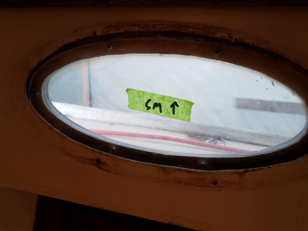
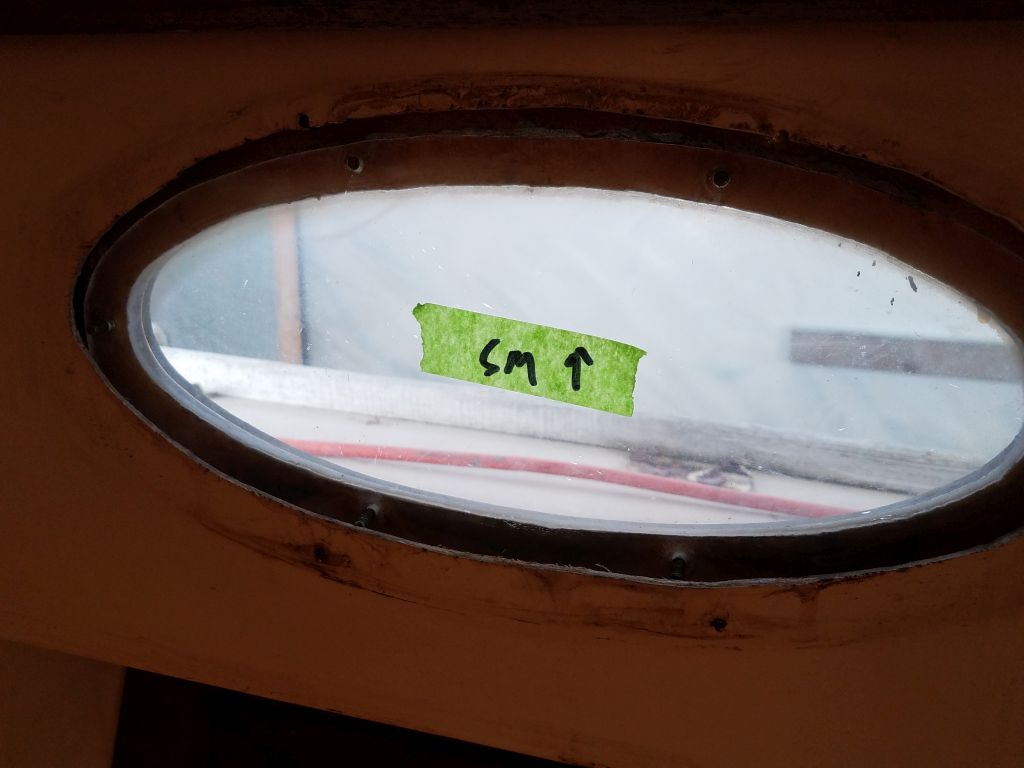
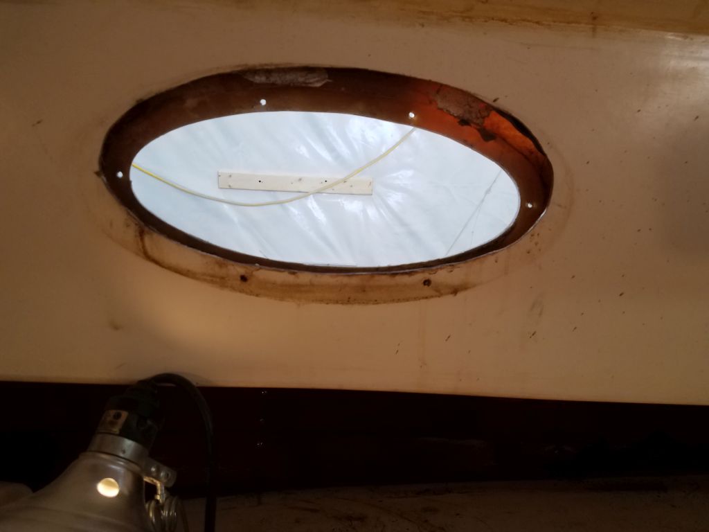
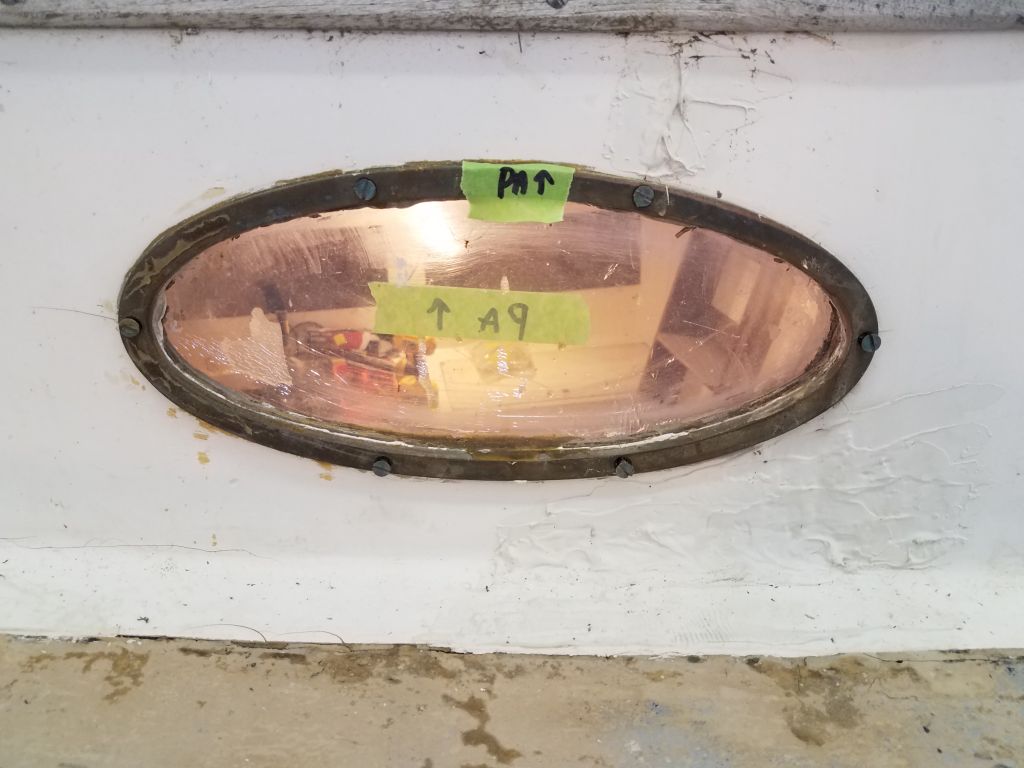
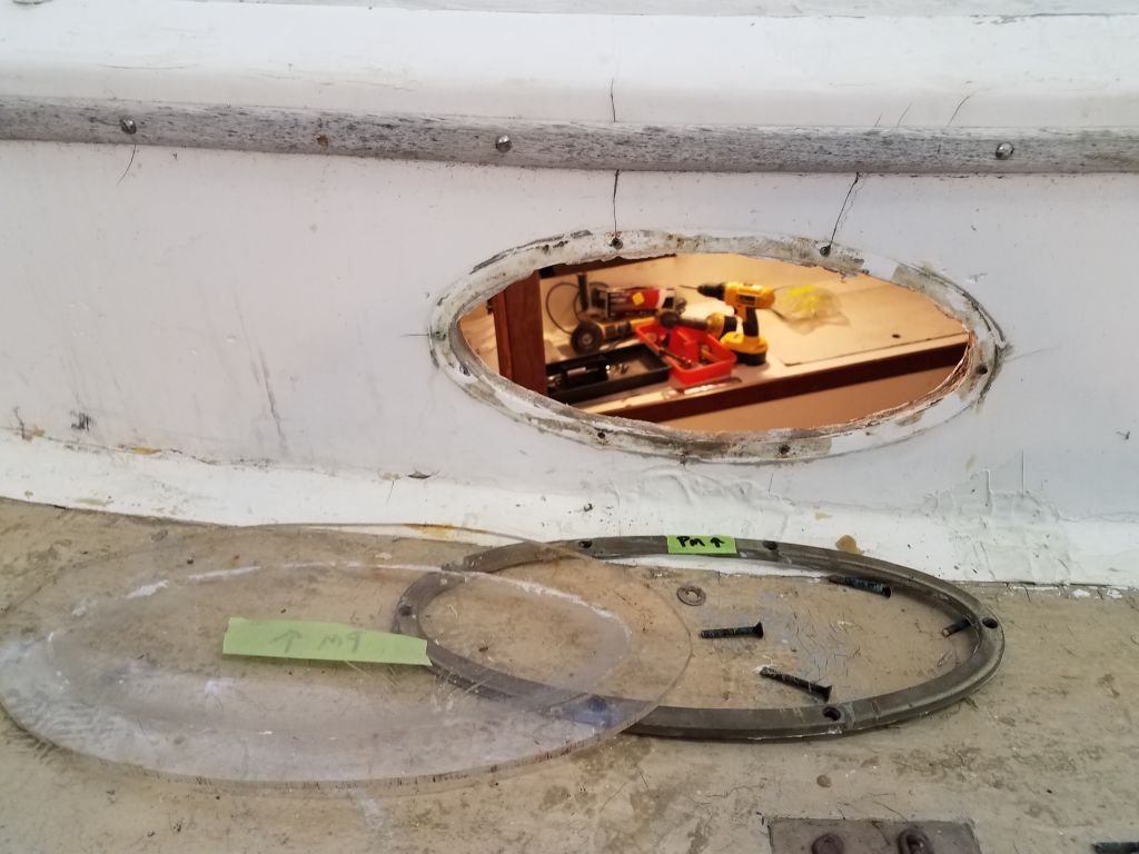
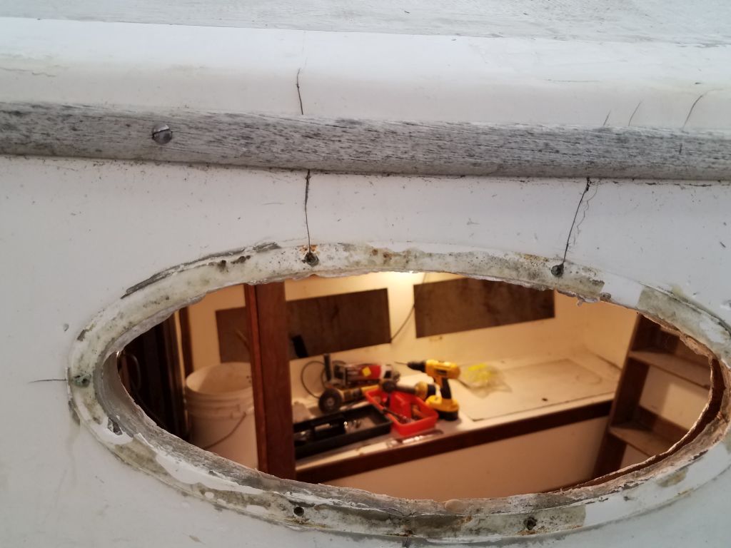
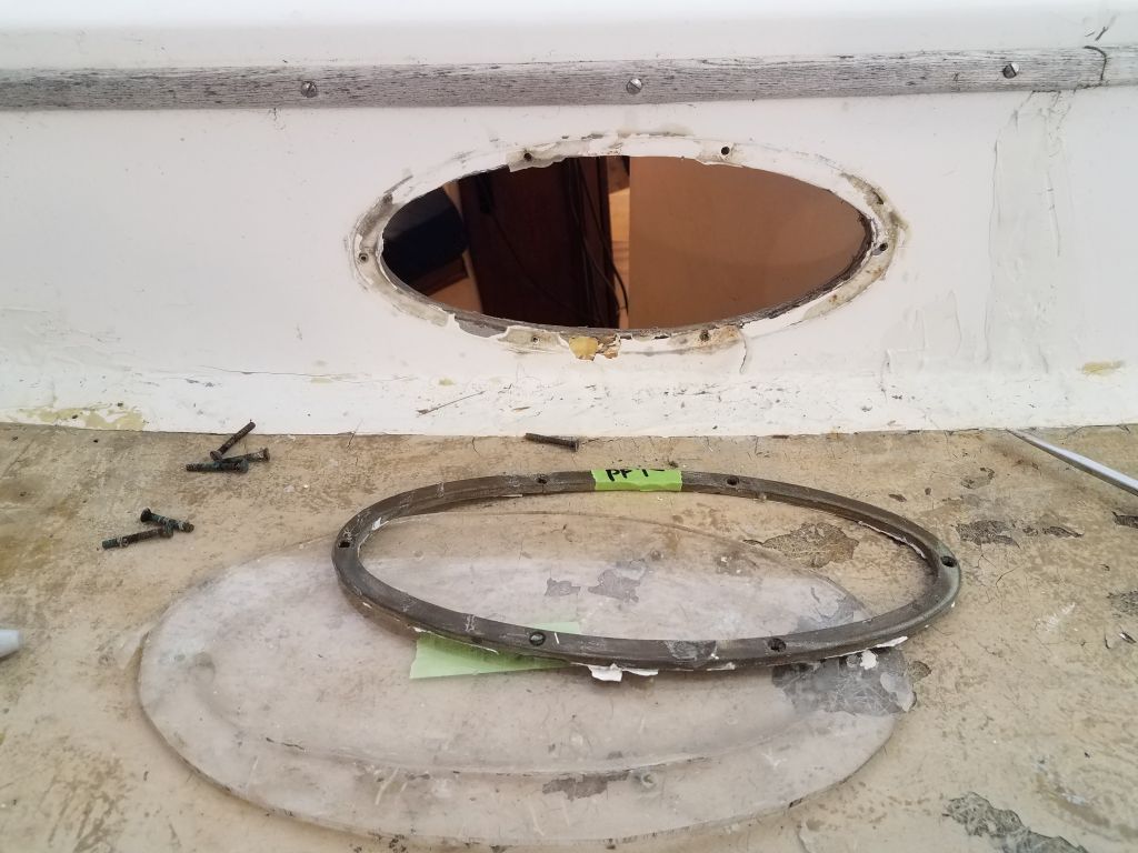
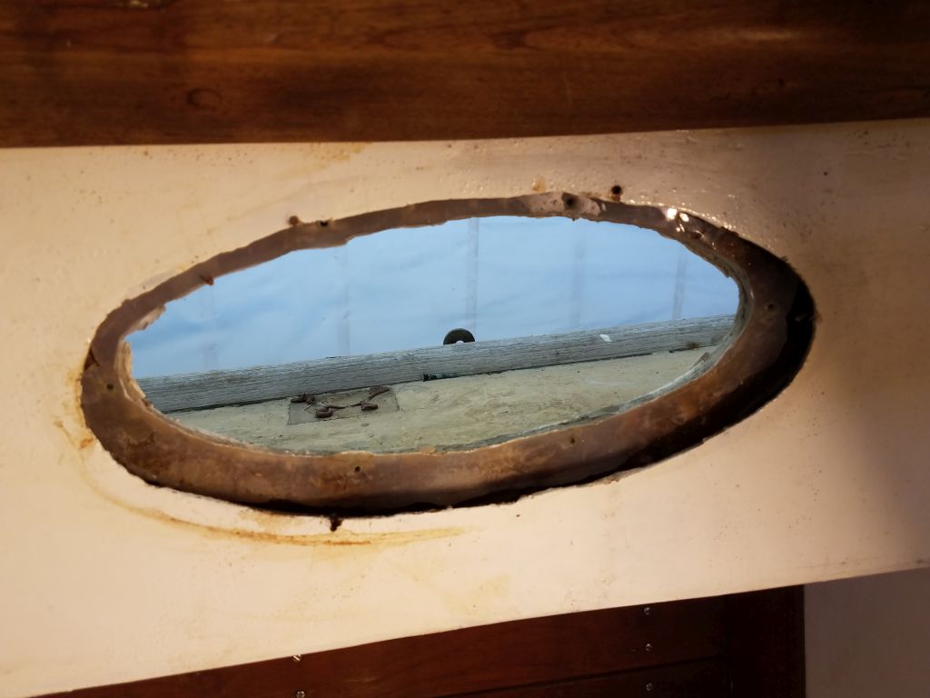
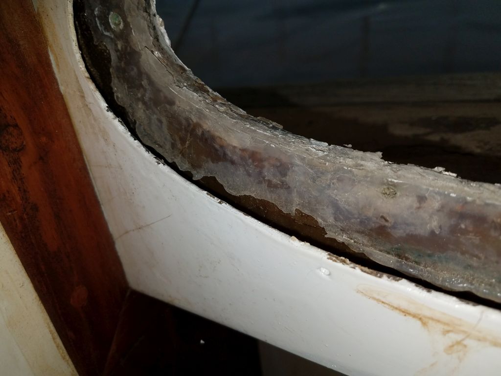
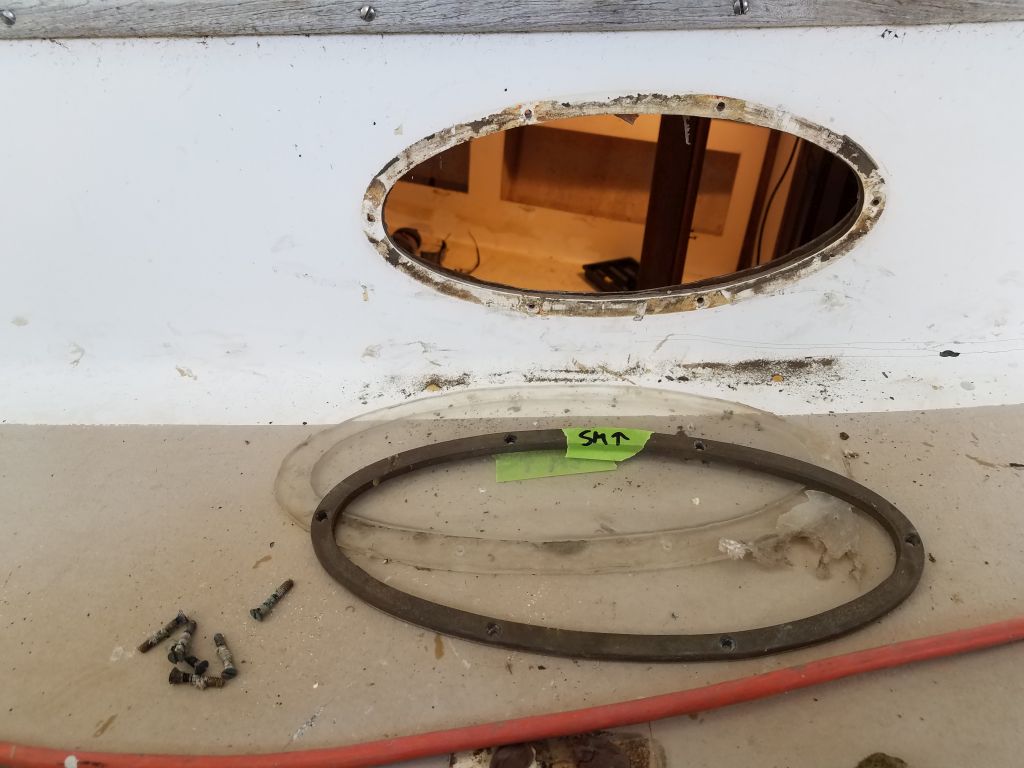
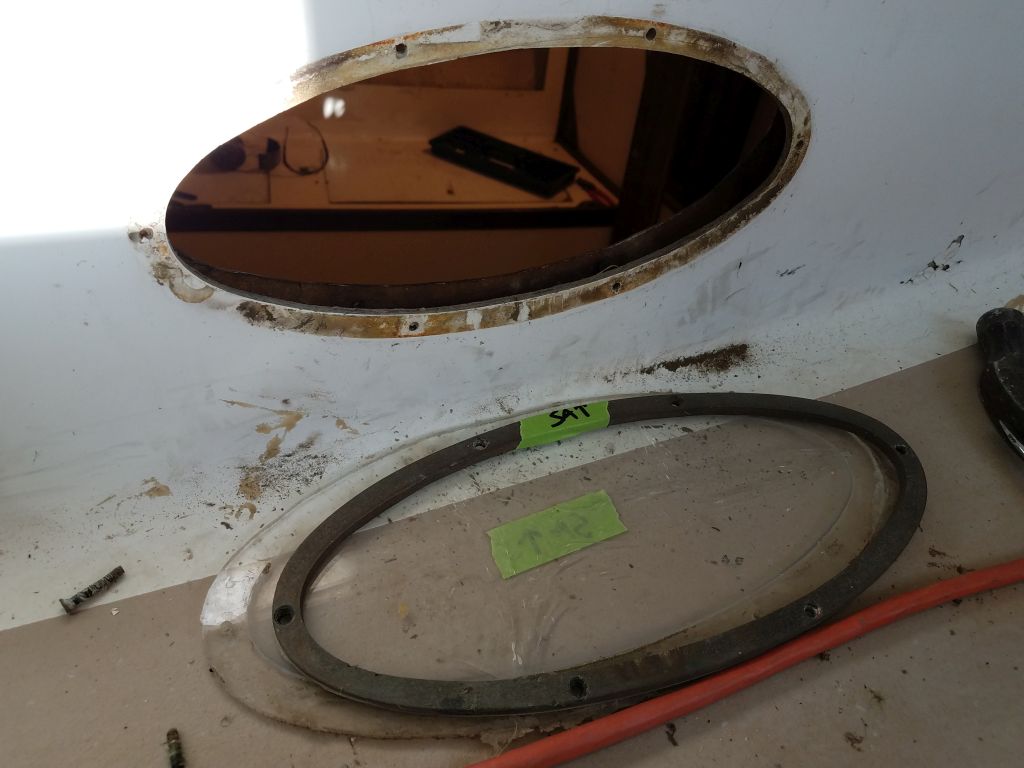
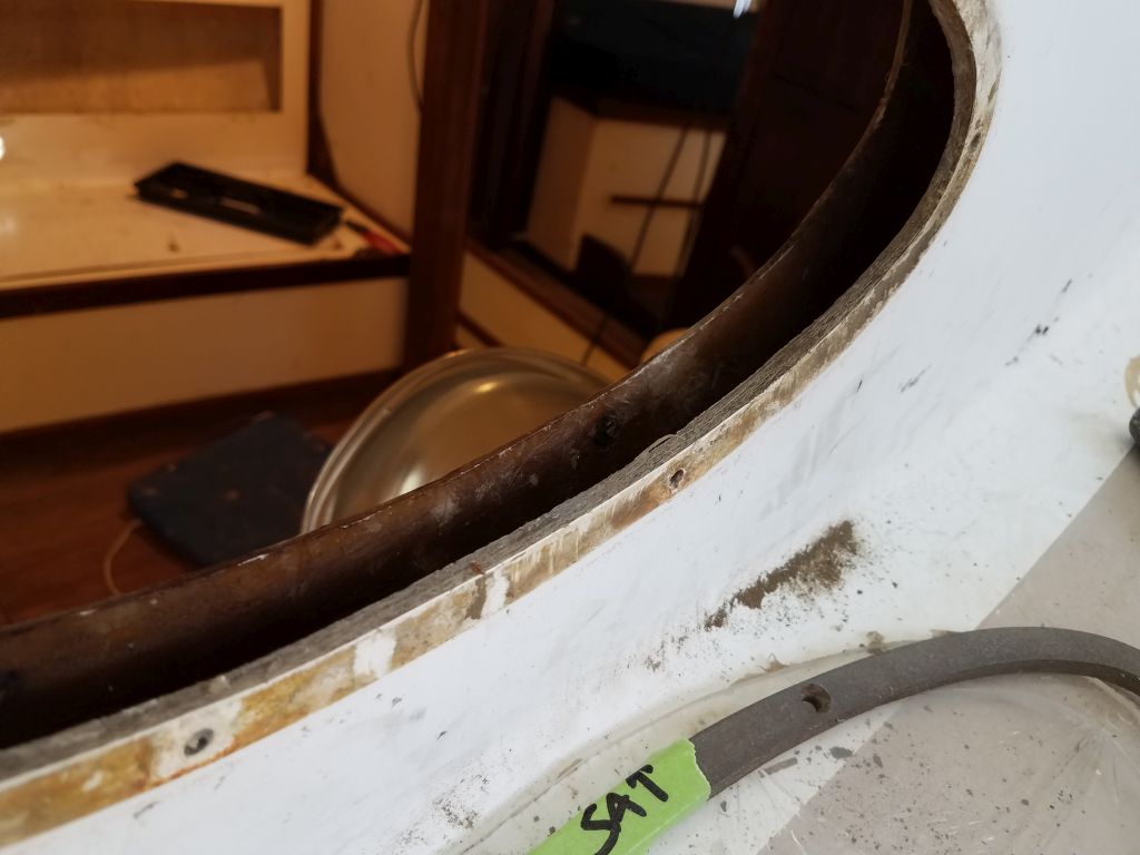
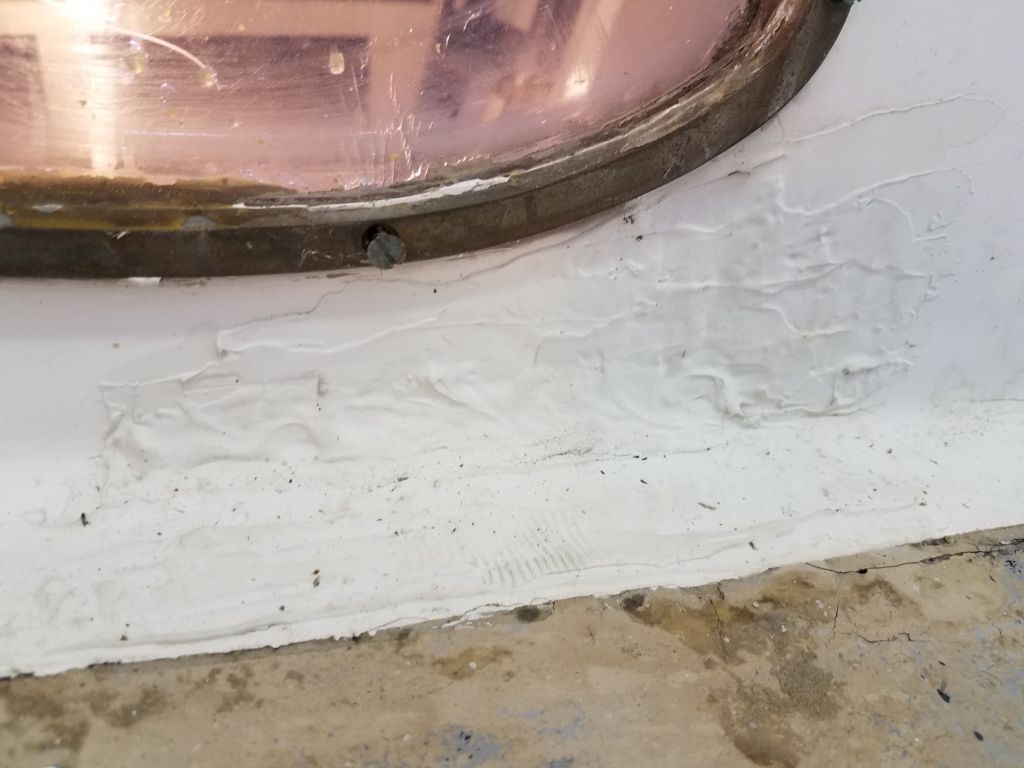
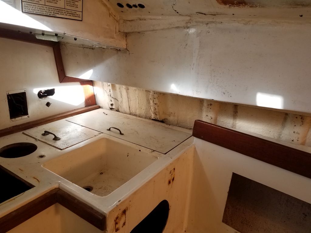
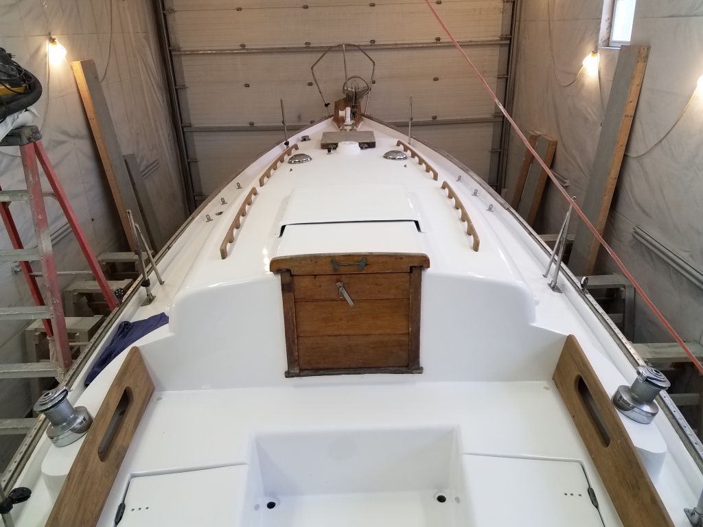
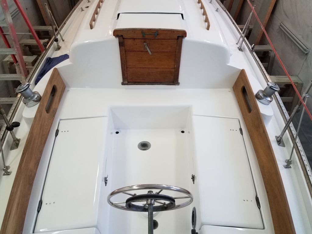
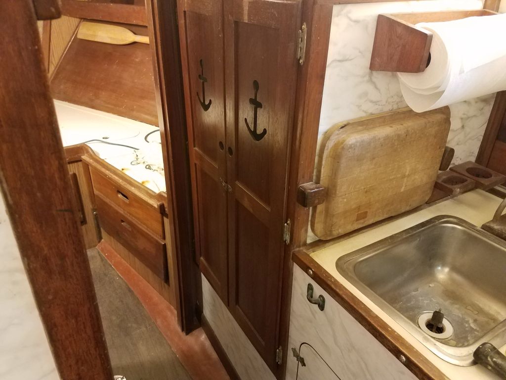
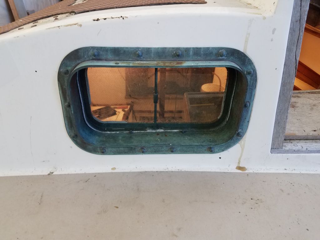
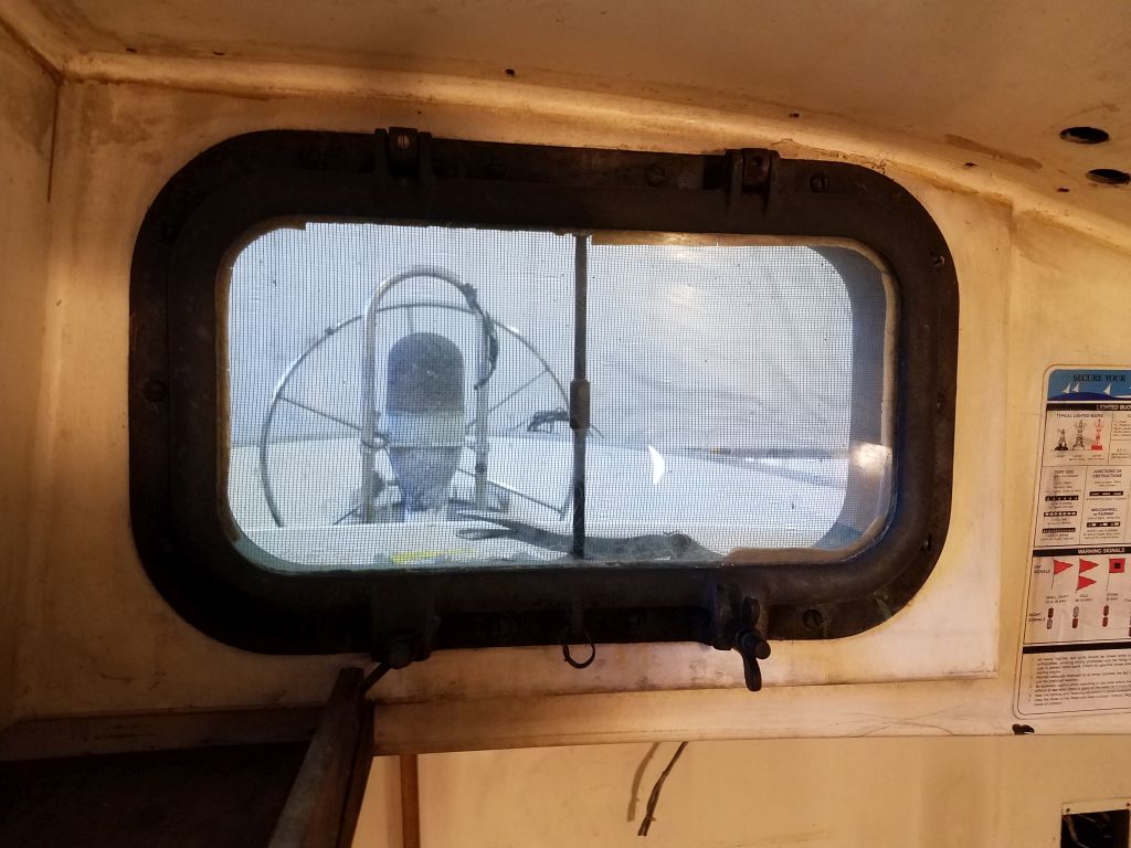
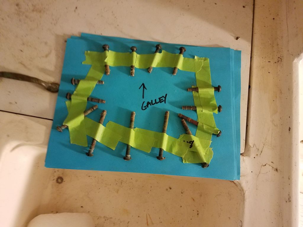
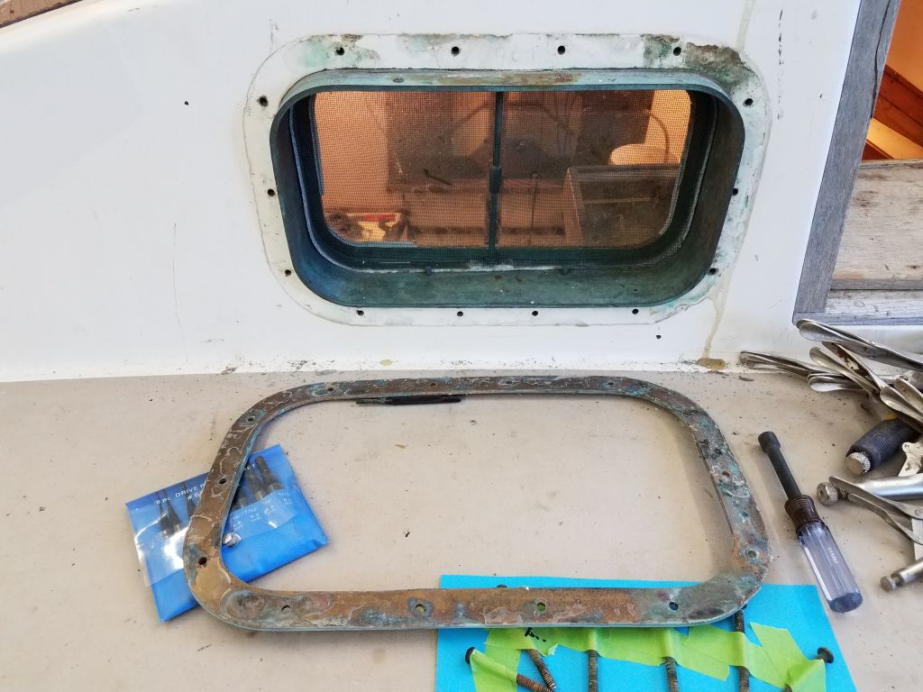
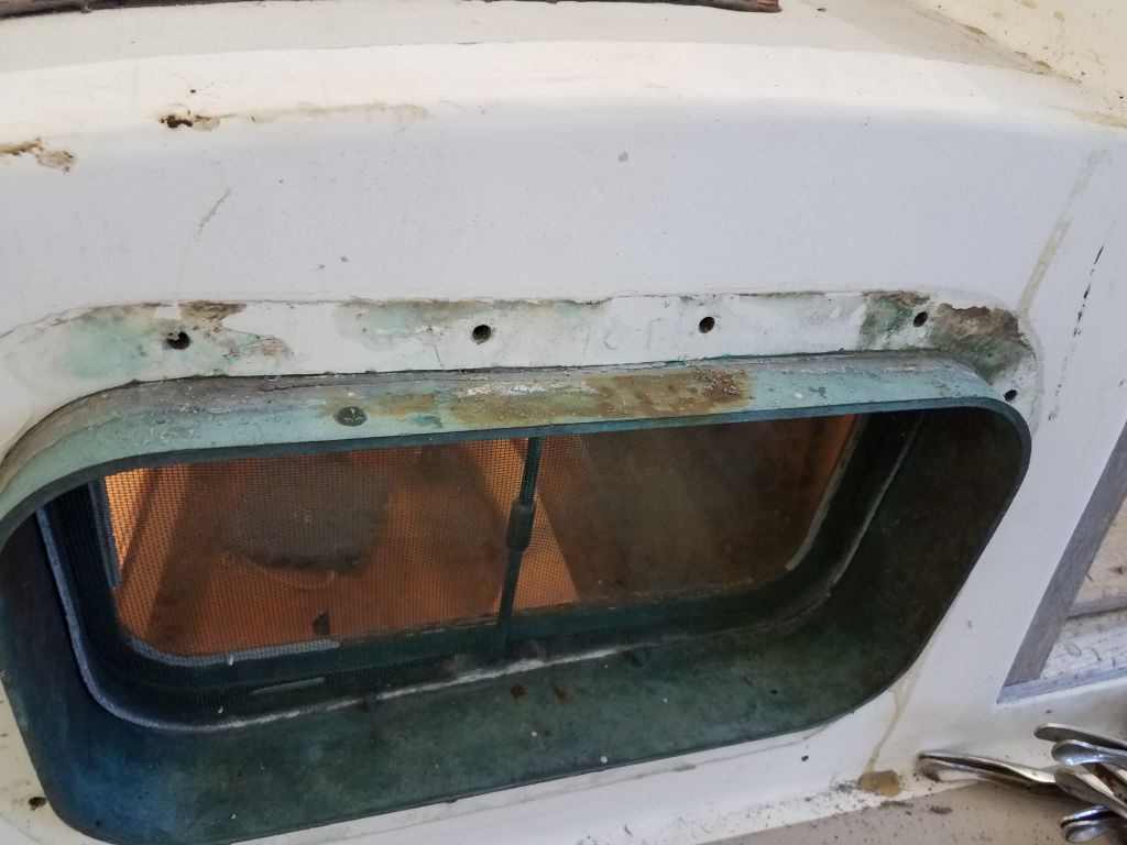
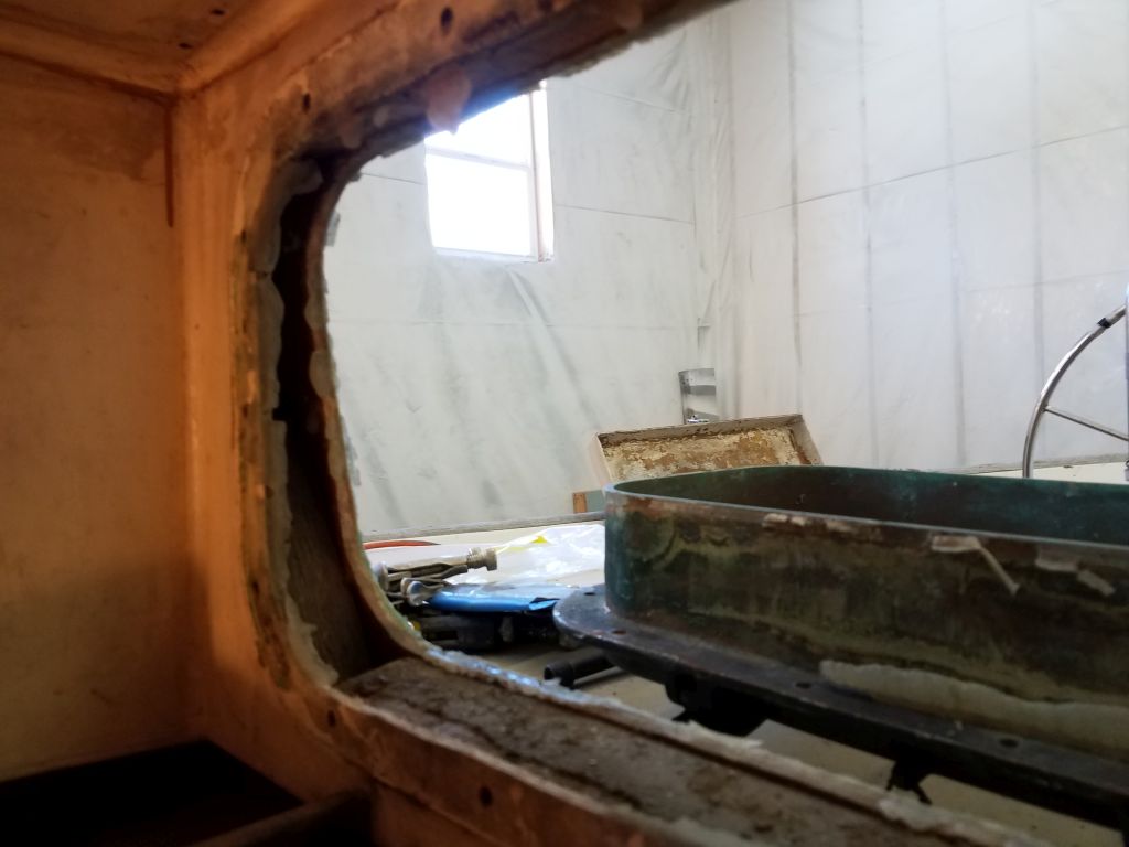
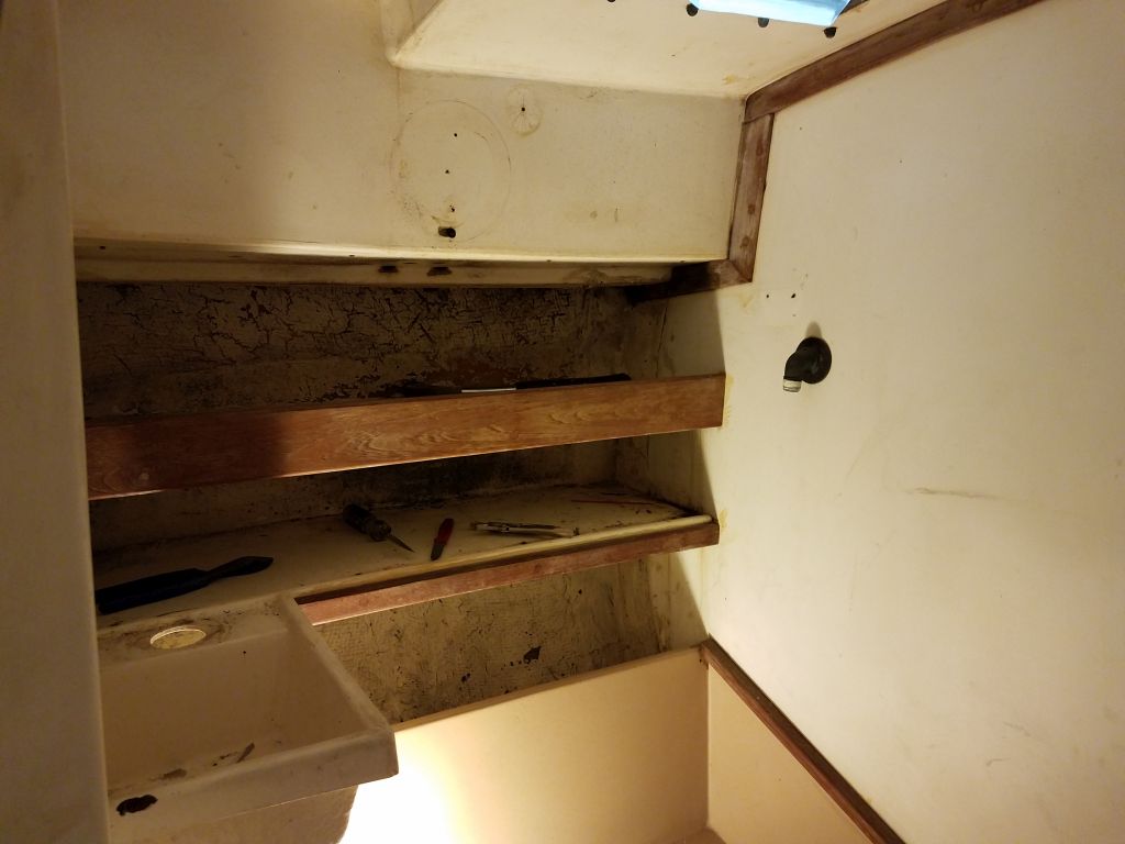
There was a huge bronze opening port above the galley, facing aft into the cockpit, and I removed this now without any particular difficulty, though the spigot was an extremely tight fit through its opening.  As always, I secured the fasteners in order for future reference, since there were several different lengths used around the perimeter.

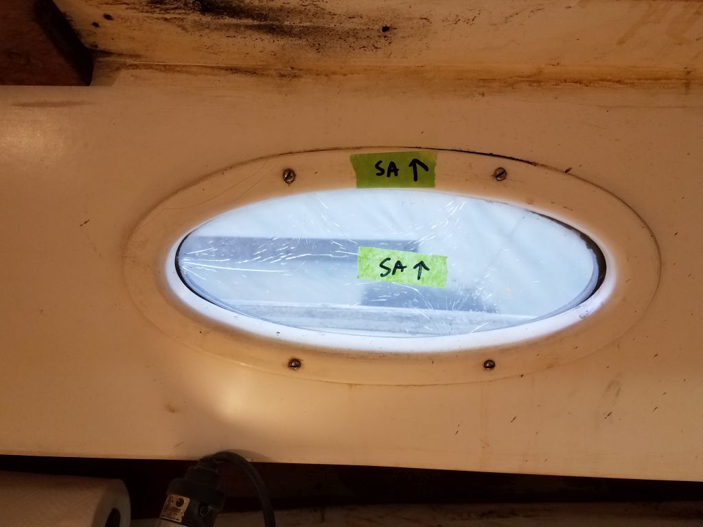
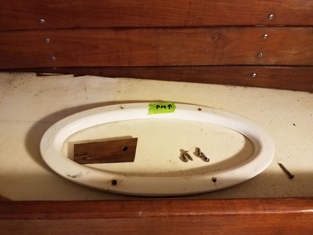
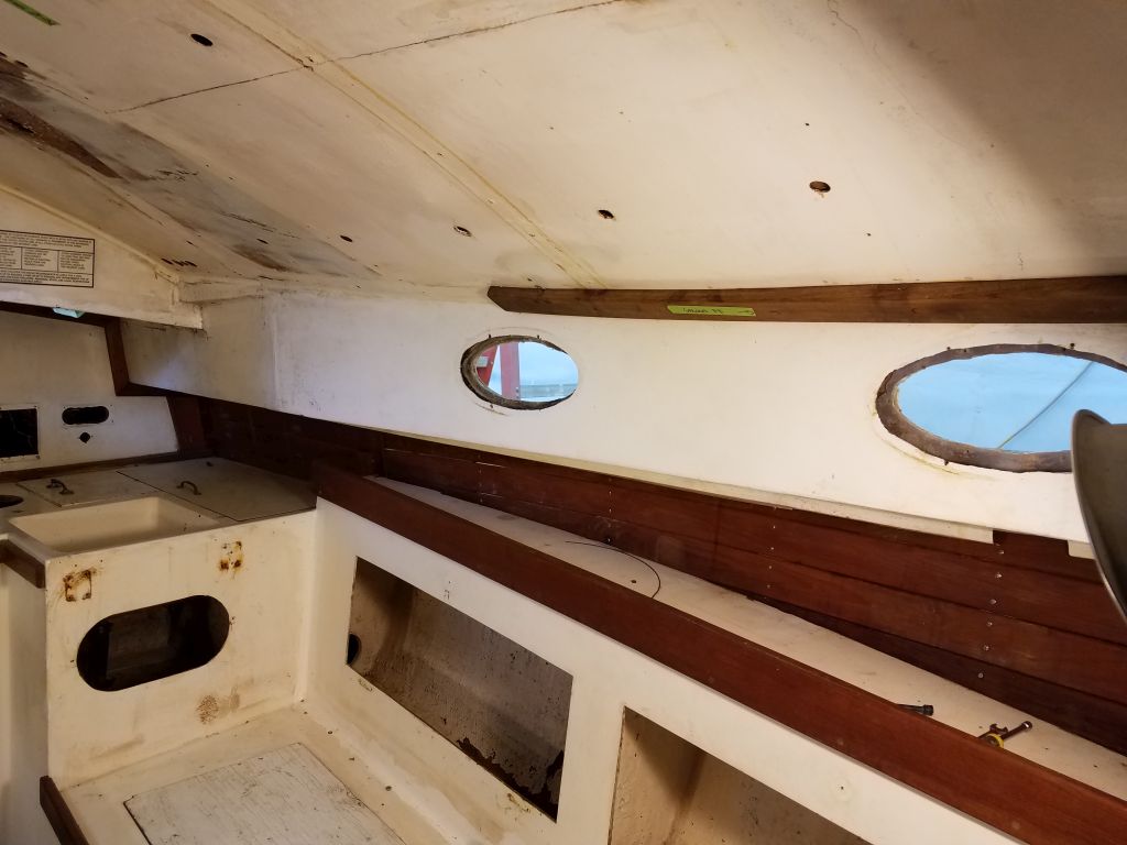
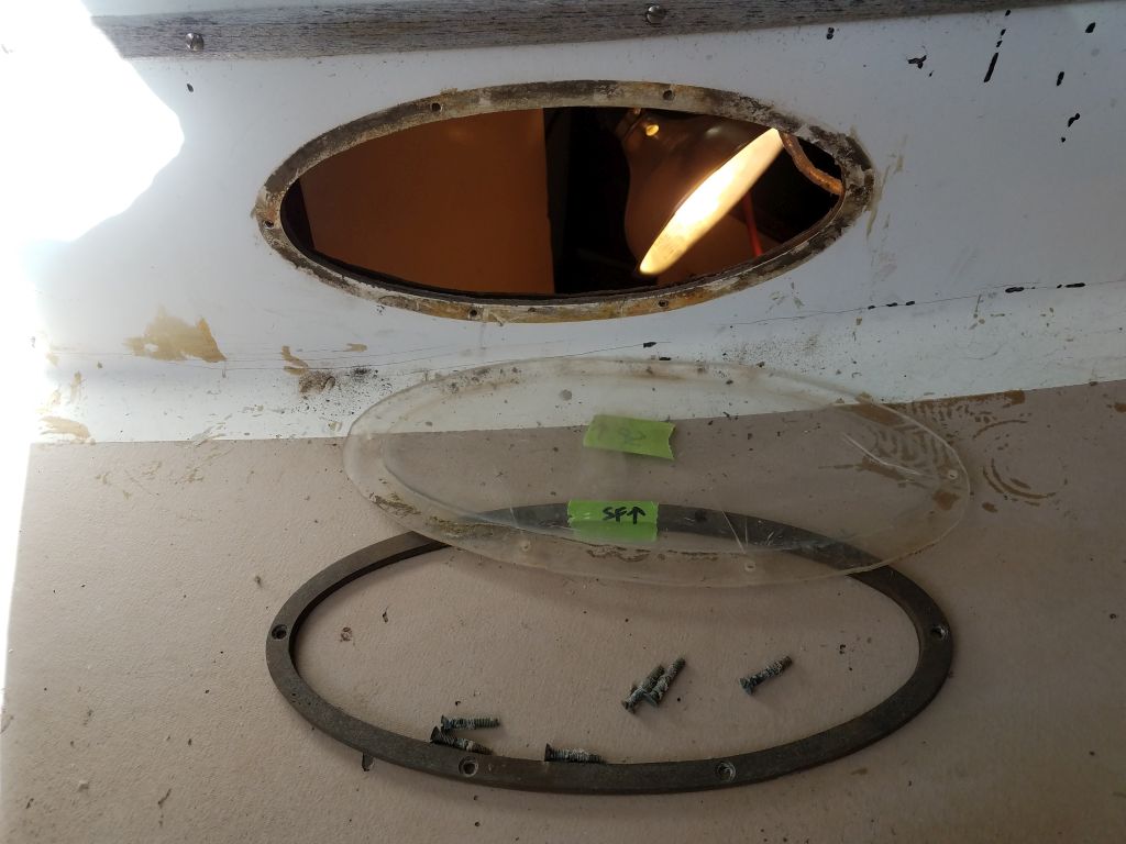
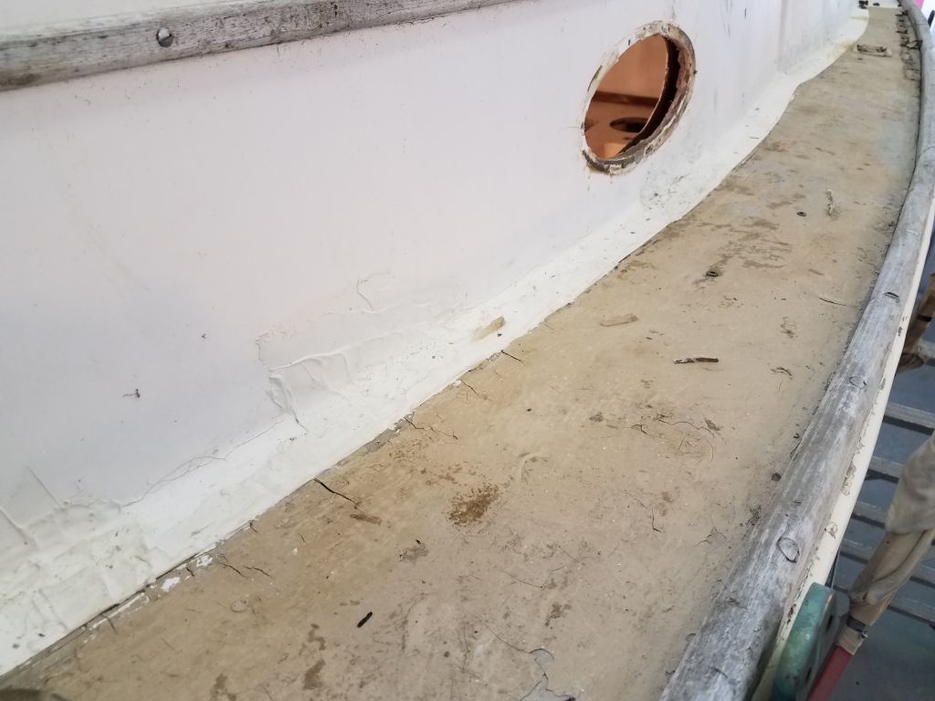
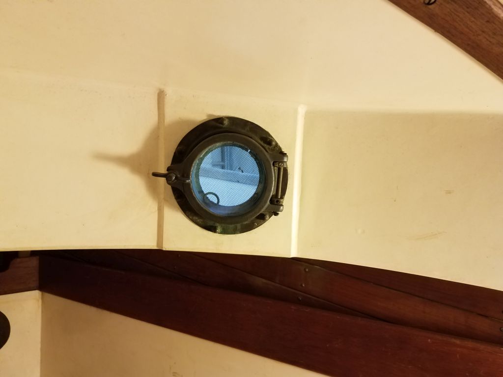
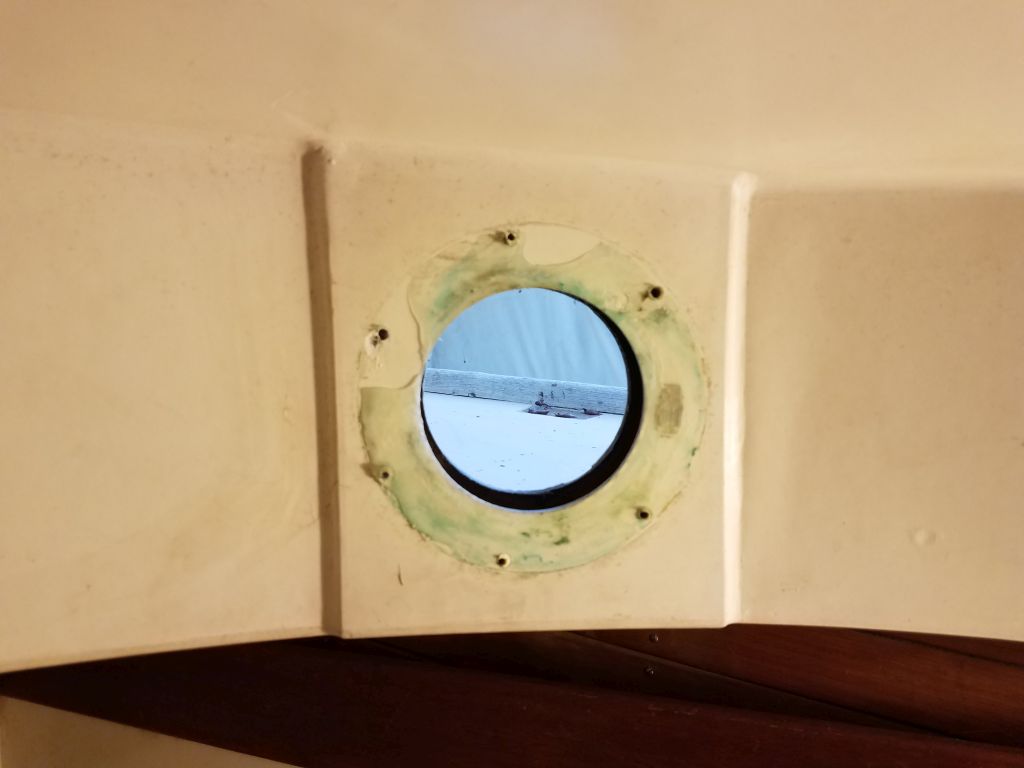
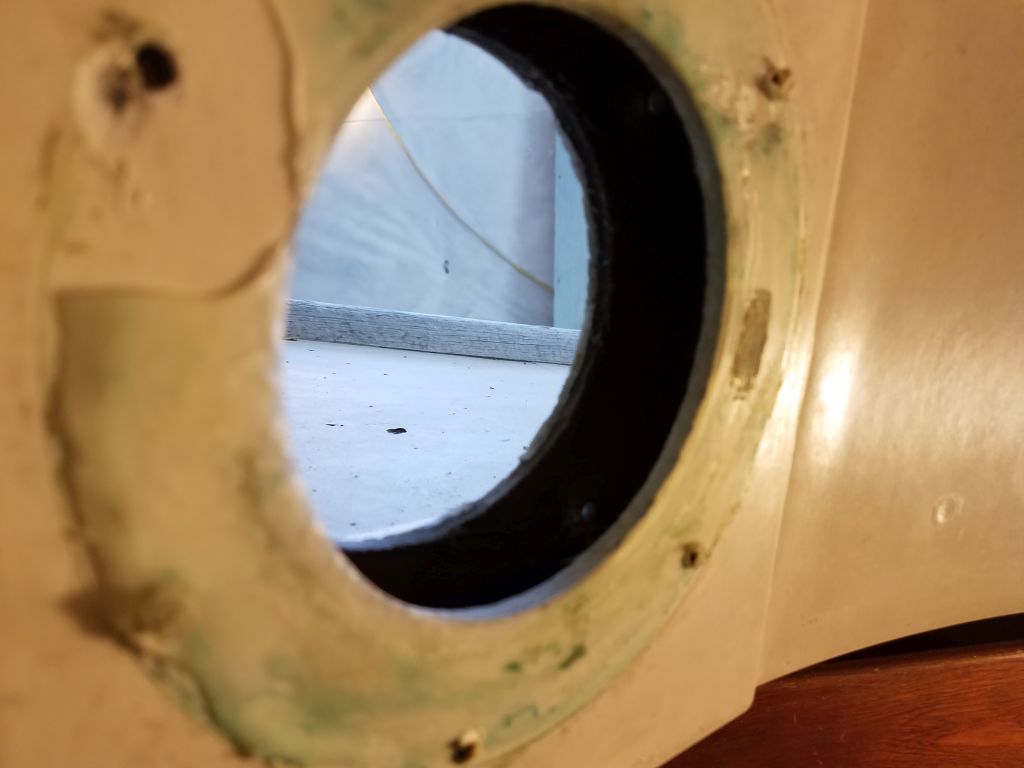
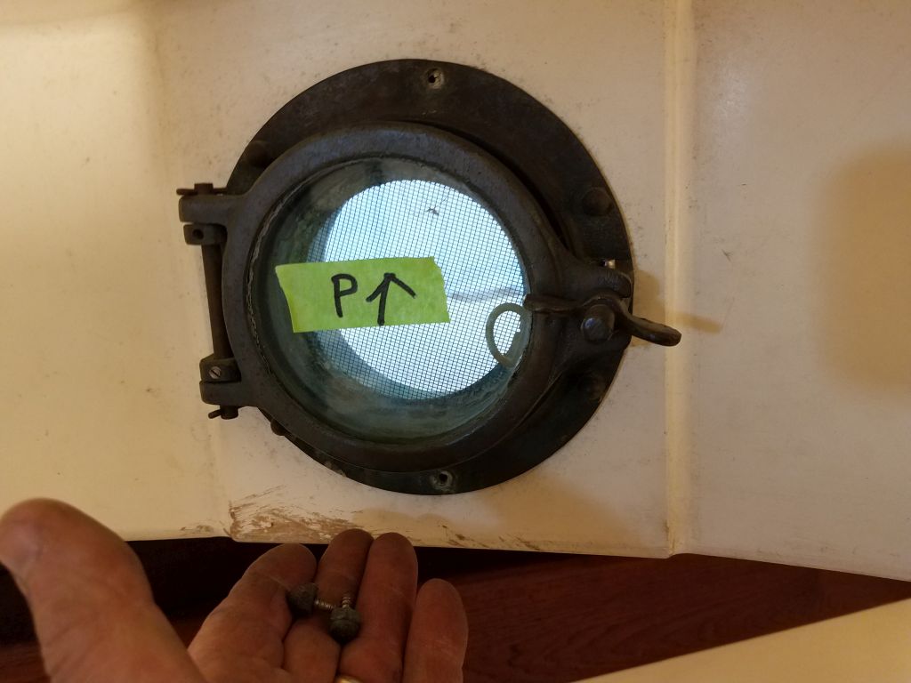
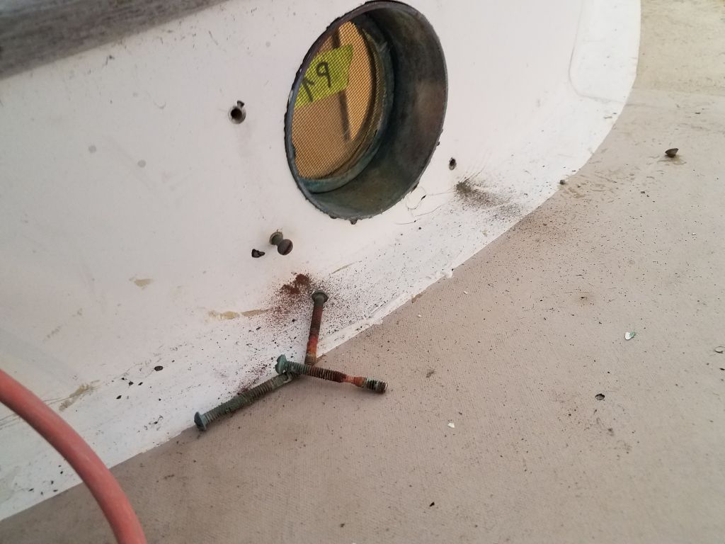
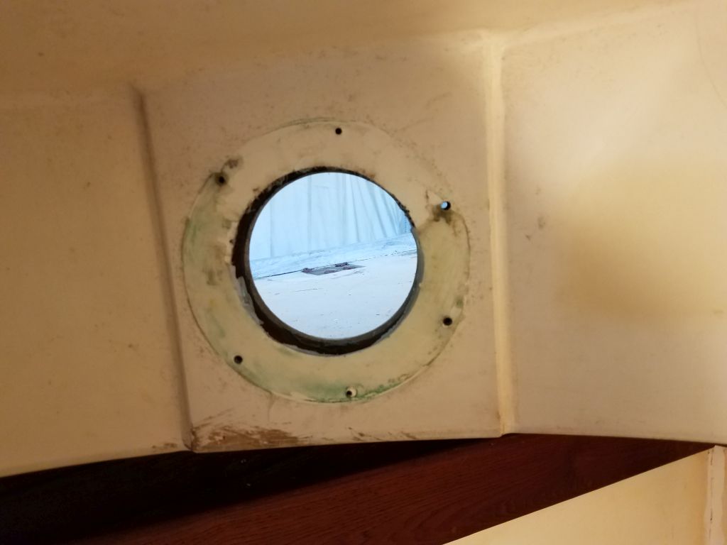
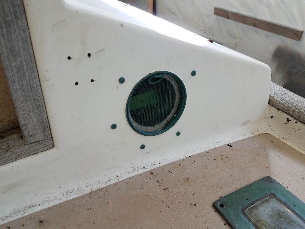
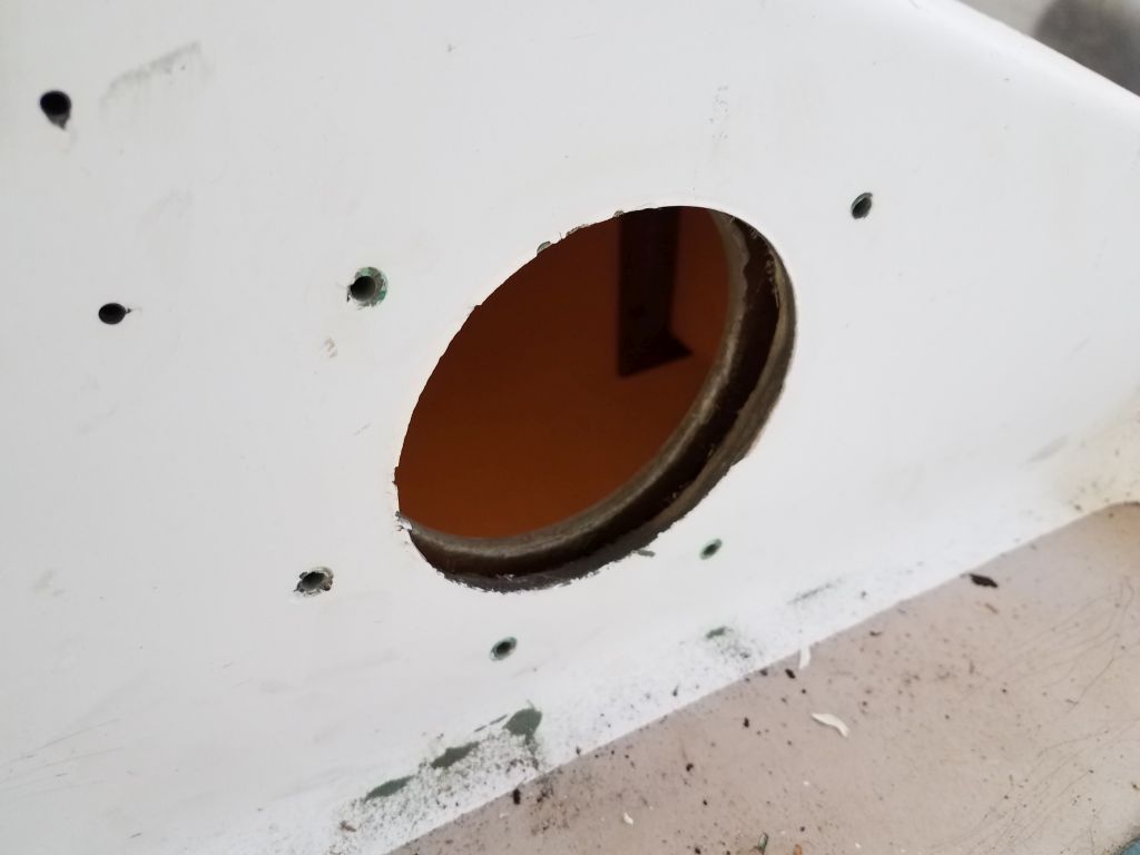
In the forward cabin and in the head, there were small round bronze opening ports, and I removed these next with no issues of note.

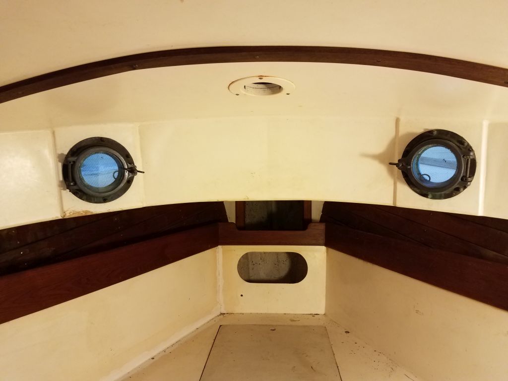
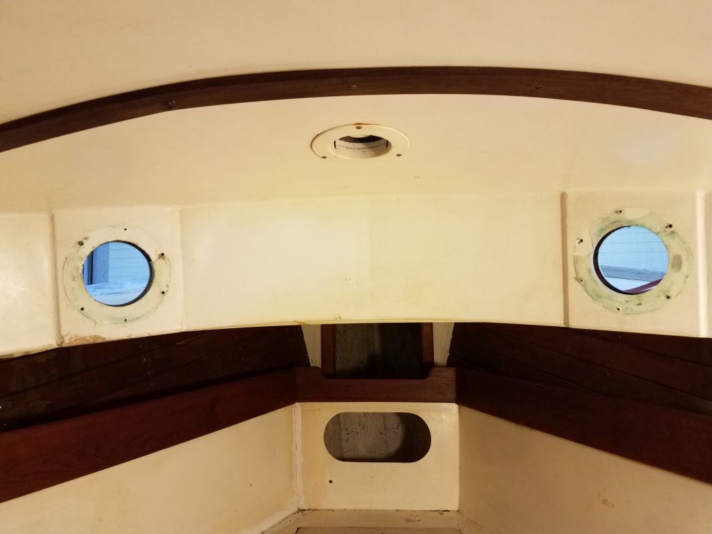
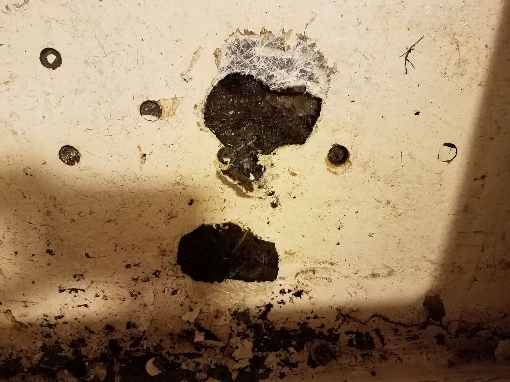
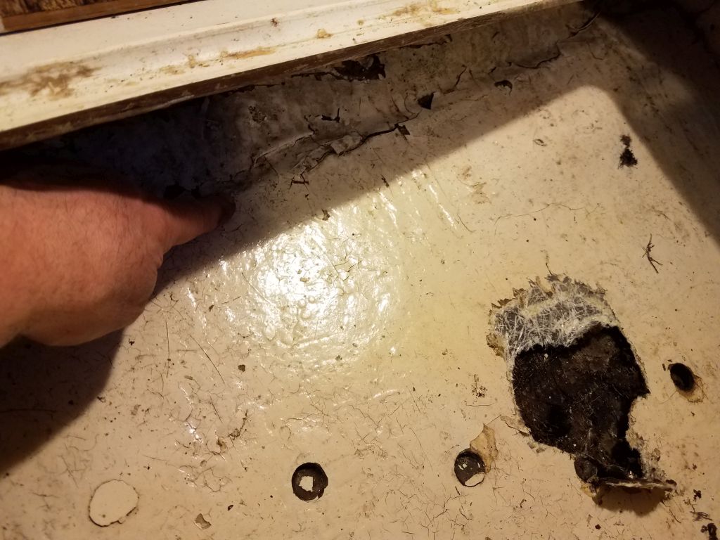
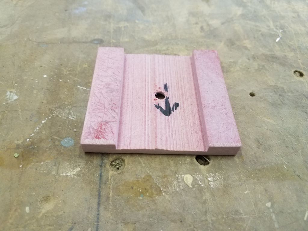
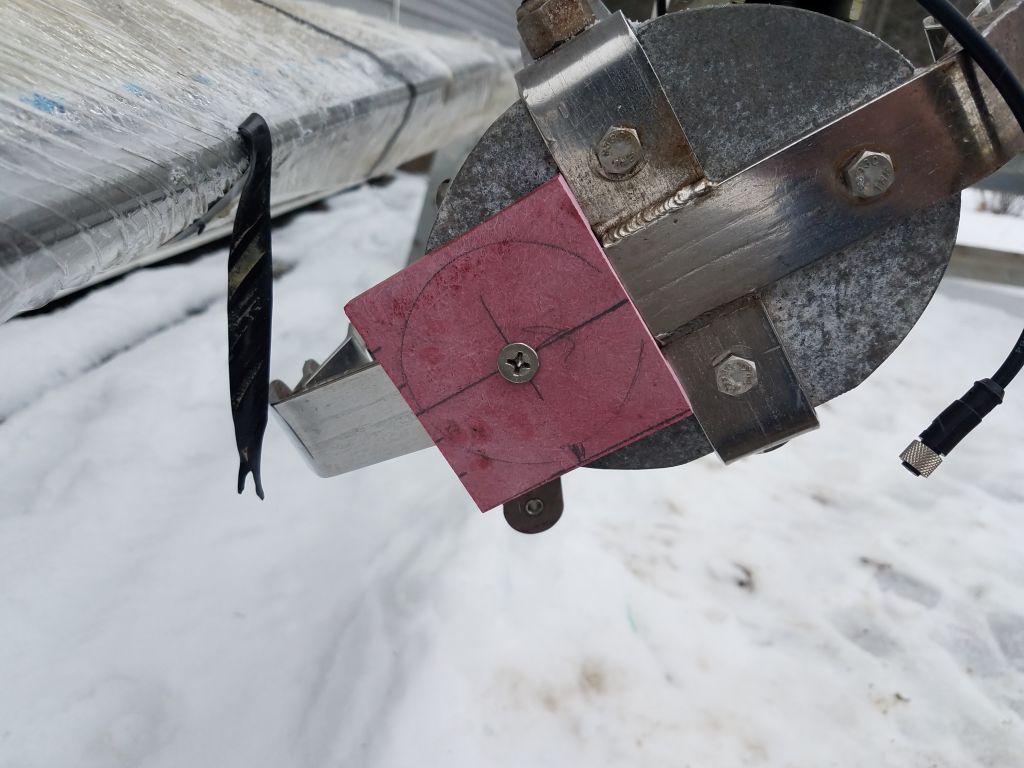
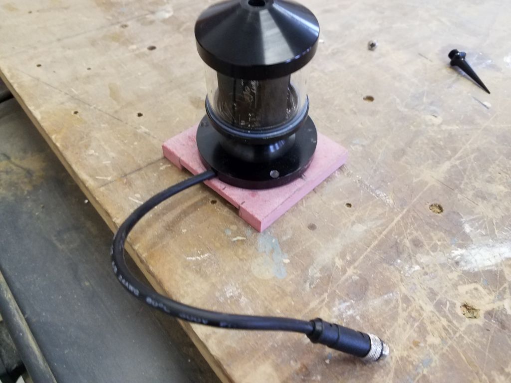
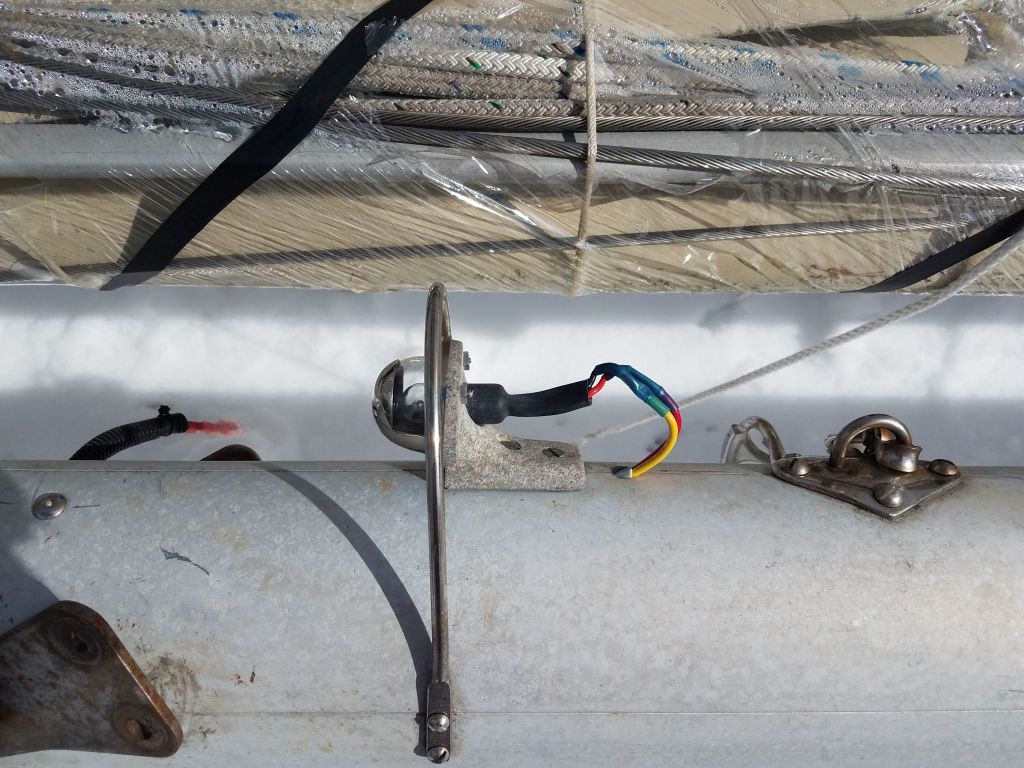
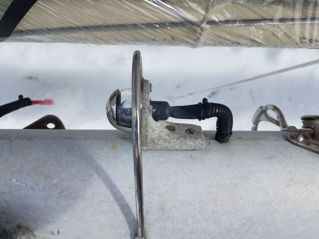
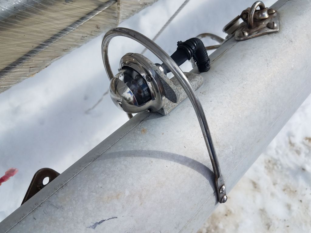
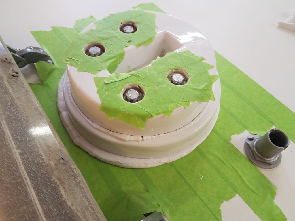
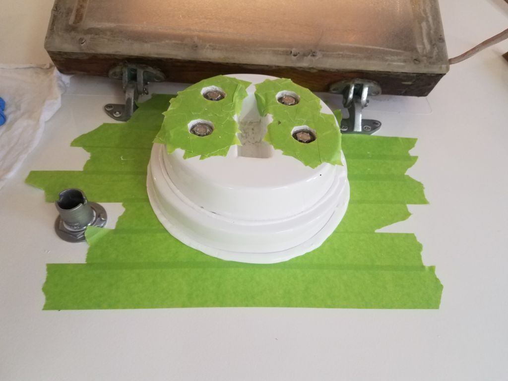
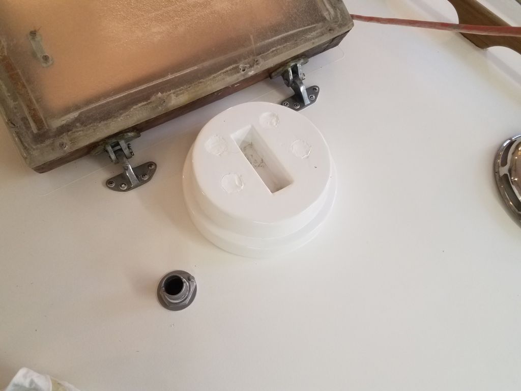
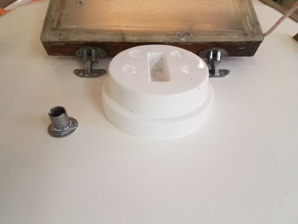
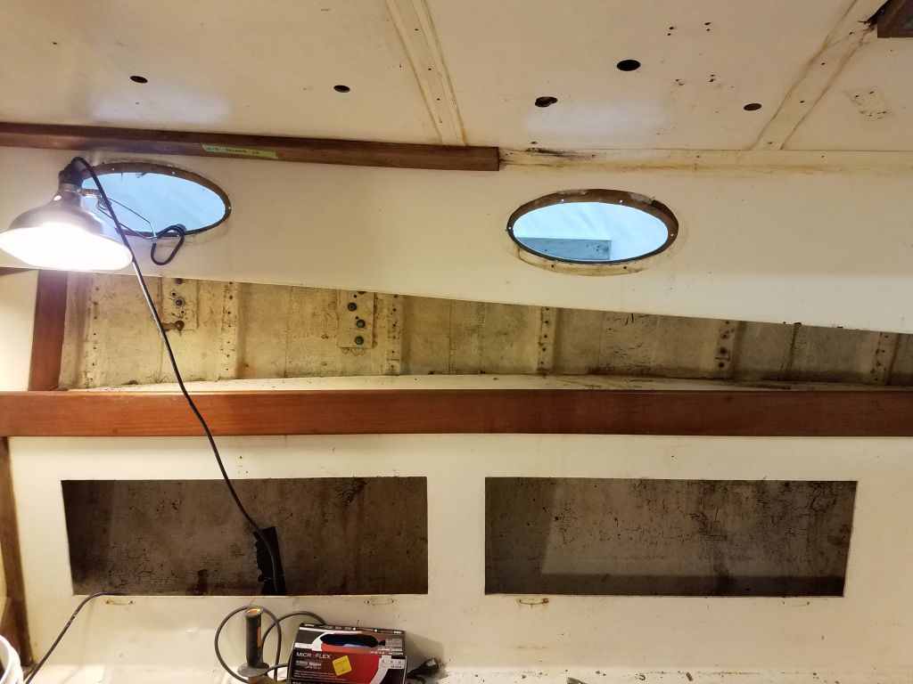
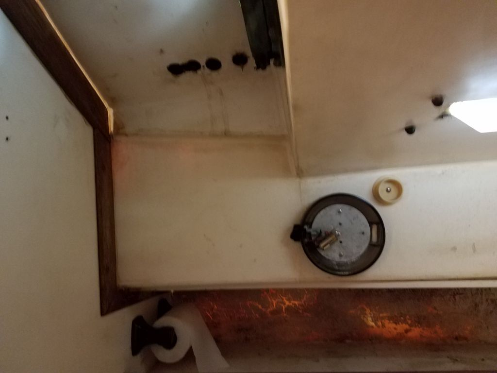
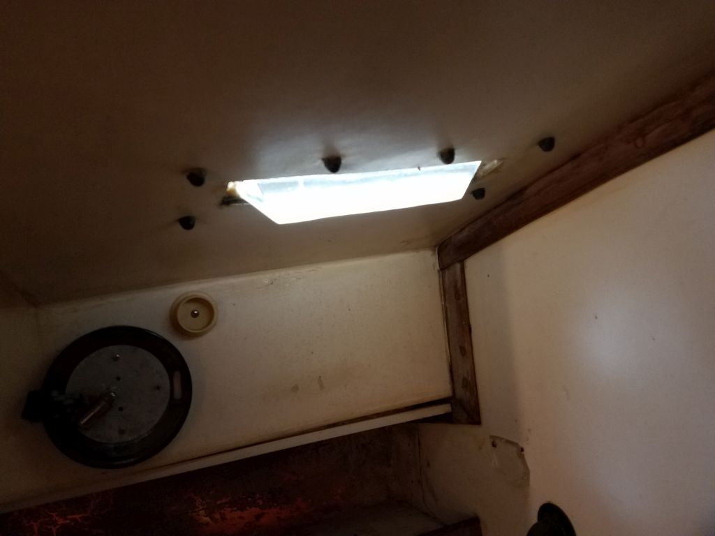
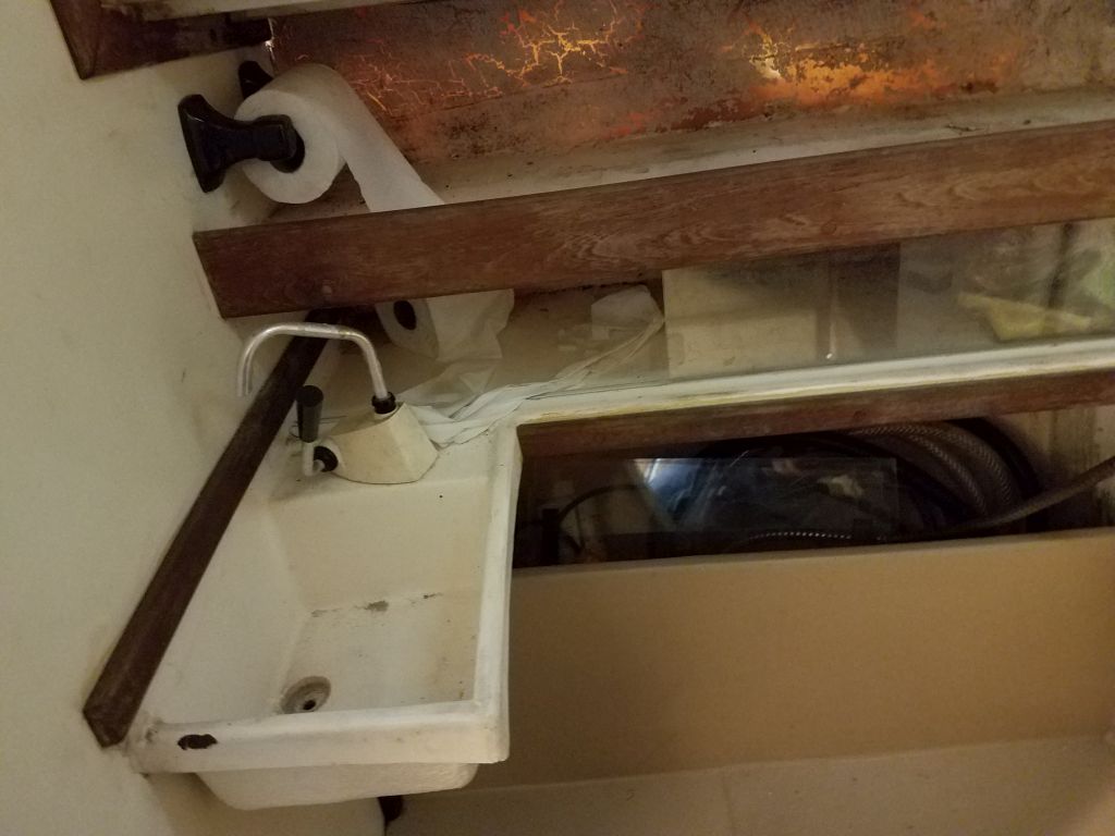
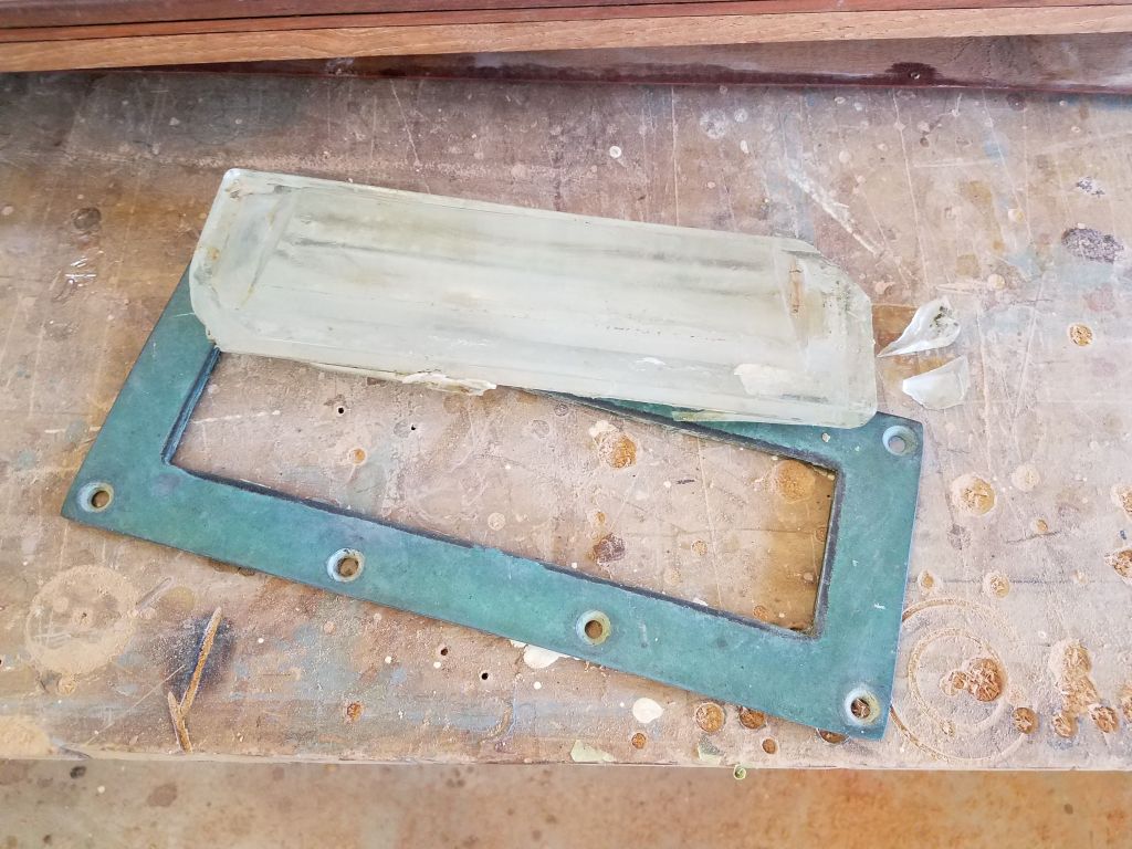
Finally, I removed a light fixture and some hoses from the head area (fortunately there was no old toilet nor holding tank to deal with here), along with an overhead deck prism that had leaked badly (along with its counterpart over the galley), and which had both caused obvious core damage to the wide bridgedeck in the cockpit.  I’d soon get to removing the galley deck prism, but I found the glass on the one above the head was broken in two corners before removal, perhaps from the significant deck softness and flexing caused by the rotted core.

Total time billed on this job today:  5.75 hours

0600 Weather Observation:  6°, clear.  Forecast for the day:  Sunny, near 40°

Scupper 9

< Back to Scupper

Monday

After finishing up some work on an unrelated small project in the woodshop, I got started on Scupper again  by setting up cords and lighting, and collecting some tools so I could work on preparing the boat for the substantial work list ahead.  During an earlier brief work session some months before, I’d removed most of the deck hardware, but there was plenty of dismantling remaining before I could get into the repairs and surface preparation required during this phase of the project.

I’d not done much in the cabin, other than crawling around to remove the deck hardware, so things were pretty much as I left them, and showcased the boat’s existing condition, at least on the surface.   The interior was worn and tired, though to a far lesser outward extent than the decks and hull.  Still, work here would be comprehensive, as all surfaces would ultimately require refinishing and more.  Most of the cabin structures were part of a molded interior liner, including the galley, settees, and forward cabin, offset with teak trim.  The owner didn’t anticipate much in the way of major changes to the layout or function of the cabin.

Everything easily removable had to go to open up the space and provide access to all the lockers and outer surfaces for preparation and refinishing, and in any event most of the accoutrements here were junky and needed to be removed regardless.  Starting in the main cabin, I began to systematically strip the interior, removing the settee backrests (attached with hinges to access the lockers behind) and any loose gear that remained in those lockers.   The main cabin table was secured with two bolts to the cabin sole, and I removed it to improve access throughout the space as well as to gain access to a screwed-in bilge access panel beneath.

In the galley, it looked like previous owners had replaced the flush stovetop and never used it, as it looked brand-new other than some rust staining from a drip somewhere or another.  I removed the stove for safekeeping and access.

I stripped the rest of the galley, removing drawers and locker covers, a rusty old folding countertop extension, a rickety storage unit, and the old electrical panels, along with that green pipe (function unknown) and some of the plumbing and wiring beneath the area.  The icebox was half full of dirty water and I’d have to pump that out soon.  All the locker spaces were disgusting, with years of the dirt/water/salt/oil/grunge/mold buildup that is de rigueur with neglected boats.  Any remnants of the old systems would be removed just a bit later in the process.  I removed various trim pieces as I went and if the situation called for it.

Now I opened up the bilge access panel that had been beneath the cabin table, and another access hatch in the galley, providing the first view of the bilge.  There was a flexible water tank located in the main bilge, which I promptly and messily removed and threw away (the bilge was, of course, filthy).  This revealed the tops of the keel bolts, various internal structures, and the mast step beneath the compression post above.  The mast step, built of plywood, would require thorough inspection later; there was certainly plenty of compression of the plywood around the lag screws securing it in place, but whether I’d have to rebuild it remained to be seen, though it seemed likely.  I didn’t see any other immediate issues in the main bilge, though the first order of business there–and everywhere–would be to thoroughly clean it up once I got through with the basic dismantling.

Moving on and working inside the settee base lockers, I had to halt dismantling progress for a while so I could investigate a seeming (and hopeful) quirk in the construction.  While removing part of a wiring harness on the port side, I noticed several resin-filled holes in the bottom of the locker, and further investigation quickly revealed that the lockers on both sides were lined with a cored bottom, which of course was ruined and worthless on both sides.   I could easily rip away some of the laminate on the port side, revealing blackened (ruined but dry-ish at this point) core beneath.

My consternation here, requiring immediate investigation, was whether or not this cored area was part of an overall cored structure in the hull or just something in these lockers, so I inspected other areas of the boat where I had access to the hull to look for signs of coring anywhere else, and sounded the outside of the hull in way of the lockers, hoping I’d not get the same dull thud of death that I’d found inside the lockers.

While these locker bottoms were ill-constructed and would require removal, fortunately they seemed to be just that:  liners, perhaps to help insulate the hull and reduce condensation and ruining the locker contents.  Who knows.  The  boundaries of this cored area on each side were clear to see, running from just below the settee top down to the bottom edge of the locker (top edge seen in the final photo above, just above the shadow line where I’m pointing).

In the event, I decided that, while this problem would require some extra work later, I could move on for now and continue my dismantling.

Continuing mainly in the main cabin now, I turned to the ports, or deadlights if you prefer.    These featured fiberglass trim rings on the inside, which I removed first.  Because the openings in the cabin liner were not exactly aligned with the openings in the molded cabin side, and for other reasons, some of the screws securing these trim rings were backed with little bits of wood in the gap between the liner and cabin side.

The lenses themselves were secured to the cabin side with sealant (silicone) and through-bolts from the outside, where there were slim bronze trim rings.  These elliptical ports were handsome and important to the overall appearance of the vessel, but the installation was strange–but the one constant in old boats is that there seems no end to the variety of installation techniques.

The misalignment of the openings in the liner and cabin side meant that some of the nuts securing the lenses (and outer trim rings) were easily accessible, while others were partially or fully eclipsed by the interior liner.  I used a nut driver (9mm) where I could to easily remove most of the nuts, but the ones below the edges required laborious turning with an open-end wrench, since there was no direct access for a driver or socket.  But with minimal difficulty, if not free from frustration, I removed all the nuts inside, and moved outside to remove the screws, outer trim rings, and lenses.

By the end of the day I’d removed all six ports, lenses, and trim rings.  The smooth silicone residue left behind after I removed the lenses looked like it’d be enjoyable to remove later, especially given the tight access in the space.  The lenses, once broken free from their sealant, had to be jockeyed around inside the space between cabin and liner till I could angle them out appropriately and remove them; one of them, the port forward, was quite difficult to remove in this way, though I eventually succeeded.

Working on the sidedecks highlighted the general condition of the deck areas, particularly on the port side, which seemed to have been just savaged by some previous person armed and ready with cheap gelcoat paste and a putty knife but devoid of any inkling of talent, among other issues.  The challenge–and therefore the fun–in projects like this is taking something so awful and turning it back into something nice (or maybe even better than nice) again.

Finally, to round out the day, I removed the trim and ceiling strips (hull liner) from the port side above the galley and settee.  This exposed the after two main chainplate fasteners (the chainplates were bronze mounted externally to the hull), with slim stainless steel backing plates.

Total time billed on this job today:  6 hours

0600 Weather Observation:  2°, clear.  Forecast for the day:  Sunny, 30°

Jasmine 71

< Back to Jasmine

Friday

Taking advantage of about the best outdoor conditions I could hope for in the near future, I moved Jasmine outdoors to open up the shop for a new project.

Total time billed on this job today:  1 hour

0600 Weather Observation:  30°, mostly clear.  Forecast for the day:  Sunny and windy, high around 34°

Scupper 8

< Back to Scupper

Friday

Just over a week earlier, after several weeks of above-normal temperatures and no snowstorms, the ground around Scupper’s storage area had been bare and easily accessible.  Alas, two hefty snowstorms over a period of only 5 days changed that, and just a few days before I was planning on shuffling boats and moving her indoors.

After both snowstorms, I shoveled out around the jackstands to keep them from freezing into the ground or ice, and after the second (larger) storm on March 13, I took advantage of warm-ish post-storm temperatures to move the rest of the snow from around the boat, cleaning out an area with abundant room for my trailer.

Now, after another day’s wait while I attended to another project and gave the area a bit of melting time, I had as good a chance, weatherwise, as I was likely to get in the foreseeable future to move the boat indoors:  sun and temperatures on either side of freezing, with the ground firm after overnight.  So after I moved out the project I just completed, I picked up Scupper on the trailer and moved her in.  I didn’t bother removing the tarp, as I just wanted to get the move completed, but with some gusty winds I did take the precaution of cutting off what I could to prevent it from possibly becoming a sail in a wind gust.

The move was uneventful and I was  grateful to have her safely indoors, where she could thaw and melt off and I could get to work in the near future.

Total time billed on this job today:  1 hour

0600 Weather Observation:  30°, partly clear.  Forecast for the day:  Sunny and windy, high around 34°

Lively Heels 2

< Back to Lively Heels

Friday

In addition to the support trim for the table top when installed in the down position, I needed a few pieces of fiddle trim to replace the original trim.  The new trim would be removable for when the dinette was converted to a full-size berth, but would still be needed at other times to hold the cushions in place.  I milled up the pieces I needed, referring to my measurements for lengths.  I also prepared two long pieces of simple 1/4″ wide trim that I would use to cover the plywood end grain in the dinette opening once the main trim was installed.  I edge-milled as needed and sanded all the trim pieces smooth through 220 grit.

The table top blank required a few additional milling steps.  I planned to install one fiddle at the outer edge, needed to hold the filler cushion in place when in use, but the owner thought it’d be best to leave the remaining three edges un-fiddled.  However, we did elect to mill some little recesses to hold pens and the like, so now I set things up to mill these with my router and a sign-making bit I had that would make the appropriate profile.

After determining where I wanted the grooves, and measuring the router and bit as needed, I clamped on a straightedge at an offset (in this case it was 3-3/4″ from the edge of the table) against which to hold the router and mill the grooves in a straight line.  Then I routed the details on the three sides of the top.

Afterwards, I milled 1/4″ roundover details on the four bottom edges of the table top and on the top outer edge, where I planned the fiddle.  For the inner three top edges I switched to a 1/2″ roundover bit for a smoother profile.  Once I’d routed all the edges, I sanded the whole tabletop to 220 grit.

Finally, after solvent-washing, I applied a sealer coat of varnish to all sides of all the new trim and table top.  I’d continue building up the varnish over the next few days before switching to rubbed-effect varnish for the final coat to match the existing interior finish.

Total time billed on this job today:  2.25 hours

0600 Weather Observation:  30°, partly clear.  Forecast for the day:  Sun and clouds, windy, around 34°

Lively Heels 1

< Back to Lively Heels

Thursday

Back in January, I visited Lively Heels in the owner’s storage building so I could discuss with him the addition of a dinette table and possible conversion to a full-size berth.  The existing space had been constructed to allow for a table with a 3-sided dinette seating area, but the table had never been installed.

The outcome of our discussion at the time was that a basic pedestal table, sized to fit the footwell opening in the existing dinette, was the best option for the space and for the owner’s needs.  At the time, I took some basic measurements of the space and noted the details, and later, back at the shop, I spent a few hours preparing and dimensioning some raw cherry stock to glue up a blank for the new table top, along with some pieces sized for the trim I thought I’d need.

The table was to be removable and serve double duty as the platform for a berth filler cushion that would make the dinette into a larger lounging or sleeping area.  Standard table pedestals have traditionally left much to be desired in terms of strength, looks, and durability, so finding a decent yet simple pedestal for this application was an important task.  Complicating the installation in this specific case was the fact that the center of the existing dinette footwell, where a pedestal foot might be located, was directly over some beams that supported the cabin sole (I knew this because I built the interior originally some years earlier), and this obviated the use of any sort of flush or insert-type pedestal base.

After some searching, I found a pedestal that featured an aluminum leg that fit into a neat-looking nearly flush surface-mount base.  Intrigued, I ordered the pedestal so I could inspect it firsthand.  The base itself, made of stainless steel, was very low profile–a plus for this space since we didn’t want a bulky pedestal base in there–and had what turned out to be a highly effective means of securing the table leg tightly.  The top of the assembly was a plastic piece that would be secured to the table, and fit over a tapered section of the leg for a tight friction fit.

Later, after various scheduling and weather-related delays, I returned to the boat to prepare the space for the new work.  My task this day was to remove the existing fiddles from around the space, which would reveal the true size and shape of the opening that I needed to fill, and allow me to determine the various new trim profiles I needed to make up.

The existing cherry trim was mitered at the outside corners, so to make a clean end for the side trim that would remain in place, I cut through the trim just outside of the dinette area and existing miter cut.

Next, I drilled out the bungs hiding the fasteners securing the fiddles in place, and removed the screws.  The fiddles were also glued in place, but with some care I was able to remove the pieces with minimal damage, so hopefully I could repurpose some of the hardwood later.

During the original construction, I’d installed a hardwood cleat beneath the plywood settee overhang to support the fiddles.  This was secured with glue and more screws.  The screw heads on the settee were filled with paint, so I chiseled out the cleats from beneath and then used locking pliers to unwind the screws enough till I could grab and remove them from above.  This left me with just the overhanging plywood settee top, which is what I wanted and would provide the clean start for the new trim.  At this stage, I also sanded clean and rounded the edges of the remaining fiddles at the sides of the dinette, and applied a coat of varnish over the raw wood.

I made various detailed measurements of the opening for my future reference in building the new trim.  The trim would have to support the table top flush with the settee when lowered to the berth position, and also needed to cover the now-exposed plywood settee edge.  I planned to run the trim back beneath the existing overhang to give it plenty of strength, but I hadn’t worked out all the details of how I’d mill it just yet.  To give myself an accurate template of the exact opening, I laid the table blank across and traced the outline on the bottom side–the easiest way I could come up with to document the real space.

For visualization purposes and to ensure the table leg was the desired height, I set up the leg and table top, giving a sense of how it would work later, even though the table was still an oversized and incomplete blank at this point.

Back at the shop later in the afternoon, I got to work on the details.  For the main support trim, I planned to use some 3″ wide cherry that I’d milled and sanded to a rounded profile on one edge.  Allowing for a 3/4″ flat to support the table, plus 1/4″ vertical trim that would eventually hide the plywood edge on the settee, this would give me 2″ of wood to extend beneath the overhang for support; I could glue and bolt it in place for high strength.  Using the measurements I’d taken earlier, along with the table template, I prepared three sections of this trim that would fit within the existing opening.   I left the side pieces a bit shorter than the actual opening so they wouldn’t project too far and run into some existing cleats, and beveled the outer edge so there wouldn’t be a sharp corner to catch clothing or legs or whatnot.

To lower the bearing surface enough so that the 7/8″ thick table top would fit flush when lowered to berth height, I added a plywood strip which, along with the 12mm thickness of the settee, would lower the installation accordingly.  The plywood would not be seen in the final installation, and I secured it to the cherry with glue and brads.

Allowing for the additional edge trim, and some space for a realistic fit, I cut down the table blank to its final size, bringing work for the day to a close.

Total time billed on this job today:  3.75 hours (plus 4 additional hours to date for the  preliminary boat visit and stock dimensioning time in January and February)

0600 Weather Observation:  26°, snow shower.  Forecast for the day:  Becoming mainly sunny, low 30s

Jasmine 70

< Back to Jasmine

Tuesday

Earlier, I’d ordered and picked up the new, simple lettering for the owner’s name and hailport, and now I installed it on the quarters and transom as requested.

To accommodate the stainless steel rigging straps that wrapped above the masthead and impacted the location for the new tricolor/anchor light fixture, I made up a little platform from fiberglass, dadoing out the base to fit over one of the straps.  To secure the base in place, I removed one of the hex bolts securing a strap at the after end of the mast, and prepared a hole in the fiberglass base through which I could install a replacement screw.  Later, I painted the little base, leaving all ready for installation at my next opportunity.

The return of winter weather, after rather a hiatus during February, came during an inconvenient time for me, just as I wrapped up this job and was hoping to move boats around and load my next project into the shop, but no one asked me first.  I’d seriously considered making the moves yesterday, before the onset of a large snowstorm, but ultimately decided to wait till after the snow.  But in any event, my work on Jasmine was essentially complete, other than a few minor tasks related to the mast, and to prepare for any opening in the next several days when I could possibly make some boat moves, I dismantled the staging and cleaned up the boat, removed protective towels and electric cords and lighting, and closed her up to await a yard move as soon as I could.

Total time billed on this job today:  2.75 hours

0600 Weather Observation:  31°, cloudy.  Forecast for the day:  Snow beginning later and becoming heavy in the afternoon and overnight, 12-24″ forecast

Jasmine 69

< Back to Jasmine

Monday

The owner requested spreader lights, and I found some nice little aluminum-housed LED lights that would do the job well.  With the spreaders on hand in the shop, I began with the basic installation and spreader-side wiring.

The lights featured a small stainless steel bracket that allowed light rotation up to 90°, which is where I needed it for this installation so that the lights would face directly down to the deck below.    After determining the position for the light and its bracket, I installed the bracket with a single machine screw into a threaded hole in the bottom side of the spreader; the bracket was designed for a carriage bolt, but that type of fastener wouldn’t work in this blind installation.  The two lights, ordered at the same time from the same vendor and while essentially identical, apparently were different “model years” and had slightly different wiring harnesses, one with a shorter black wire with a factory plug.  This did not impact much for this installation and had no practical ramifications when all was said and done.

With the lights secured in their brackets, I completed the wiring that would lead to the mast for eventual connection.  Since the spreaders might be removed in the future, I planned for plug-in connectors for the wiring.   The white wire lead on one of the lights was pretty much the right length as it was, but the black wire on the other side was shorter, so I began by extending the wires to the same length as the other side.  I added water-resistant plugs at the ends of the wires–male for one wire, female for the other, so that the mast side wiring couldn’t be accidentally reversed–then secured the wires to the spreaders with wire clamps and  flexible conduit for looks and protection.

I made up a quick test lead connector and checked the lights’ operation with a battery.  I was impressed by the light produced.

This photo shows the light bloom on the shop ceiling, about 15′ above the light itself.

With the sealant securing the chainplate covers now cured, I removed the excess and cleaned up as necessary.

I completed the electrical panel by installing a few final panel labels that I’d had to order.

Taking advantage of another decent day outside, I picked up where I left off with the mast and, using the messengers I installed earlier,  ran in the wires for the light at the masthead, spreader lights, and the steaming light, along with the VHF antenna.  At the spreaders, I led a short wire pair across from one side of the mast to the other so I could wire both sides of the spreader lights.

At the masthead, I wired up the connector for the new tricolor/anchor light. The light came pre-wired with a short harness and a waterproof (according to the light’s literature) connector, so for the moment I just connected the other side of the connector to the new mast wire.  This part of the harness was long enough that I could make the wiring connections inside the mast and just run the small harness out through a pre-existing hole in the side of the mast.

I postponed installing the fixture itself on the masthead, which had some stainless steel strops over the top that were in the way of the mounting location.  I had a plan for mounting the light and would take care of that soon.

Continuing down the mast, I made up the connections for the spreader light wiring, with the corresponding connector plugs for those I’d installed on the spreaders themselves.  I interconnected the wires from both sides of the mast and left short harnesses on each side to allow room for connection of the wires when the spreaders were installed.

Finally, I connected and installed the steaming light, using a small traditional-type fixture that fit on an existing little platform.

At the base of the mast, I led all the wires out through the wire fitting I’d installed, and, leaving ample slack for running into the boat, made up the wire terminal ends for later connection to the terminal block in the head.  I tucked the wire ends back into the base of the mast for now to limit exposure.

Total time billed on this job today:  7 hours

0600 Weather Observation:  16°, clear.  Forecast for the day:  Mainly sunny, increasing cloudiness in the afternoon, around 40°

Jasmine 68

< Back to Jasmine

Friday

With most work on board now complete, I loaded most of the gear back on board.

The riggers asked me to remove and send to them the masthead sheaves, which were to be replaced, so I headed out to the mast where, despite a recent large snowfall, the weather was surprisingly pleasant and benign.  The two sheaves and aluminum divider plates were held in place with a single bolt, and the assembly came apart easily.   I packaged up the sheaves and shipped them off.

In order to remove the sheaves, I first had to remove the existing all-wire main halyard, which led to an old Barient #3 reel winch that the owner planned to replace.  One thing led to another, and while I’d not planned on doing much in the way of mast work till better weather in a few weeks, once I got looking at the winch I decided to try removing it now.

Disaassembly was straightforward.  There was a single screw inside the winch handle socket on top of the drum, and after removing this the drum came off with minor prying from beneath, as the surfaces were dry with age.  Six machine screws held the base to the raised platform om the mast, and happily these came out without trouble, releasing the winch.  This left behind some piles of aluminum-y corrosion, but later I scraped clean the original winch pad and found it to be acceptable for re-use.

The “new” winch, a recycled Lewmar #16 self-tailer that I’d had on hand, fit the winch pad well, and I laid out, drilled and tapped the fastener holes for 1/4=20 machine screws.  I lightly coated the base of the winch with Tef-Gel, and coated all the fasteners as well during installation.

The cast mast base was just loose inside the spar, as someone had drilled out the old fasteners sometime, and I found I could slip it right out.  As with the other work this day, one thing led to another, and I decided that with the base loose and the sheaves removed from the masthead, it was a perfect opportunity to at least run in some messengers for the new wiring I needed to install.

First, though, I used a drum sander to open up an existing wiring exit hole near the bottom of the mast so it would fit my new fitting.  For this mast, since I knew the wiring hole would be accessible from inside the mast, I chose a basic plastic through hull fitting for the other end of the mast wiring conduit.  Sometimes I use surface-mount fittings, but here it was easy to install the fitting from inside.  I chose plastic for this end because I’d need to modify the fitting to accept the hose leading to the deck fitting, and in any event strength wasn’t an issue here. Since the full length of a through hull with hose nipple would be too long here, I chose this fitting based on the size of the threaded portion, which was a close match to the 1-1/8″ pipe nipple on the deck fitting.  By cutting off the hose end of a 1″ plastic through hull, I could (after installation) pare down the threads (overall diameter about 1-3/16″) accordingly to accept the other end of the hose securely.  For now, I just installed the fitting.  Later, when I had a piece of hose, I’d sand down the threaded portion to fit.

I finished up my bout of mast work for now by running in messenger lines for the masthead lighting and VHF, as well as spreader lights and the steaming light further down the mast.  I used a wire snake to pull in the small messengers, and I’d use these messengers later to pull in the wires.  I find the small messenger lines to be easier to pull wires through tight mast spaces than the unwieldy metal snake.  I was tempted to just run in the wires now too, but decided to wait till another time.

Later, the new anchor roller I’d ordered to fit the owner’s Rocna 20kg anchor arrived, and I went ahead with the installation.  The roller, a Kingston KR-2025, was a great fit for the anchor, one of the few designed specifically for this brand and size, and featured a long, deep  channel that would protect the bow platform from damage from the anchor shank.

Because of the stem fitting at the end of the platform, the roller couldn’t be absolutely perfectly aligned with the windlass and remain parallel with the platform itself.  I used a length of line to determine the most practical lead for the roller, and with just a slight misalignment from the edge of the platform, I was able to provide a lead that would work well for the anchor chain later.

Installation was straightforward with three bolts through the after end of the roller.

I test-fit the anchor in place afterwards.  This roller provided two mounting locations for a pin at the aft end:  one further aft, designed to go through a shackle or link of chain aft of the anchor itself, and one further forward (shown in use here) that fit perfectly through the  eye at the end of the anchor shank to pin it in place.  When chain through the windlass, this roller would hold the anchor tightly against the dual rollers at the forward end to prevent movement.

Total time billed on this job today:  5.5 hours

0600 Weather Observation:  30°, partly clear.  Forecast for the day:  Clouds and sun, light wind, low 30s

Jasmine 67

< Back to Jasmine

Thursday

Just a few jobs remained on my list, and I started with the main mast step, which installation I’d delayed while I built a 1-1/2″ riser to make up for the amount that needed to be removed from the mast base to eliminate a corroded area there.  Earlier, I’d used the original mast step to locate and drill holes through the riser; the riser was just a bit larger in diameter than the original step.

Using the new base as a guide, I masked off the deck areas around the base, and drilled pilot holes in the deck for the new lag screws that would secure the step.

Afterwards, I applied sealant heavily to the deck and installed the riser, then applied more sealant to the top of that and installed the mast step and lags, drawing the whole assembly down into plate tightly.

I used excess squeezeout to fill the space around the bolt head recesses, and cleaned up the residue as needed.

To finish off the chainplates, I installed stainless steel deck plates that fit over the slots and provided a harbor for sealant.  At each location, I masked around the perimeter of the new plate, then applied sealant heavily around the slots and chainplates before pressing the deck plate into the sealant.  I saw no need for fasteners.  I left the squeeze out for later cleanup once it had cured.

With work belowdecks complete, I cleaned up the entire cabin and related spaces, then turned to some minor reassembly.  Early in the project, to gain access to various hardware I’d removed some cosmetic covers from the forward cabin, along with a shelf and fiddle in the hanging locker, as well as the doors to the hanging locker , and now I reinstalled these items.  With tools and supplies gone, the cabin was empty and ready for me to start reloading the gear that had been on board when the boat arrived here.

In the cockpit locker, I’d earlier removed the connection at the aft end of the exhaust hose, which had allowed greatly improved access to the spaces there for hardware and wiring work.  Now, with work complete, I reinstalled the hose, securing it with clamps and heavy wire ties as needed to route it along the cockpit locker opening and up along the coaming before turning down to the existing outlet.

Still ahead, I’d finish up a few minor things and load gear back on the boat.  In addition, I had a short list of work to do on the mast, including running new wiring and installing light fixtures, and I would take care of that in due course as allowed by the vagaries of late winter and spring weather.

Total time billed on this job today:  6.25 hours

0600 Weather Observation:  29°, heavy snow and windy, about 6″ from overnight.  Forecast for the day:  Heavy snow during the morning, then tapering off later in the day, around a foot total accumulation expected

Older posts Newer posts