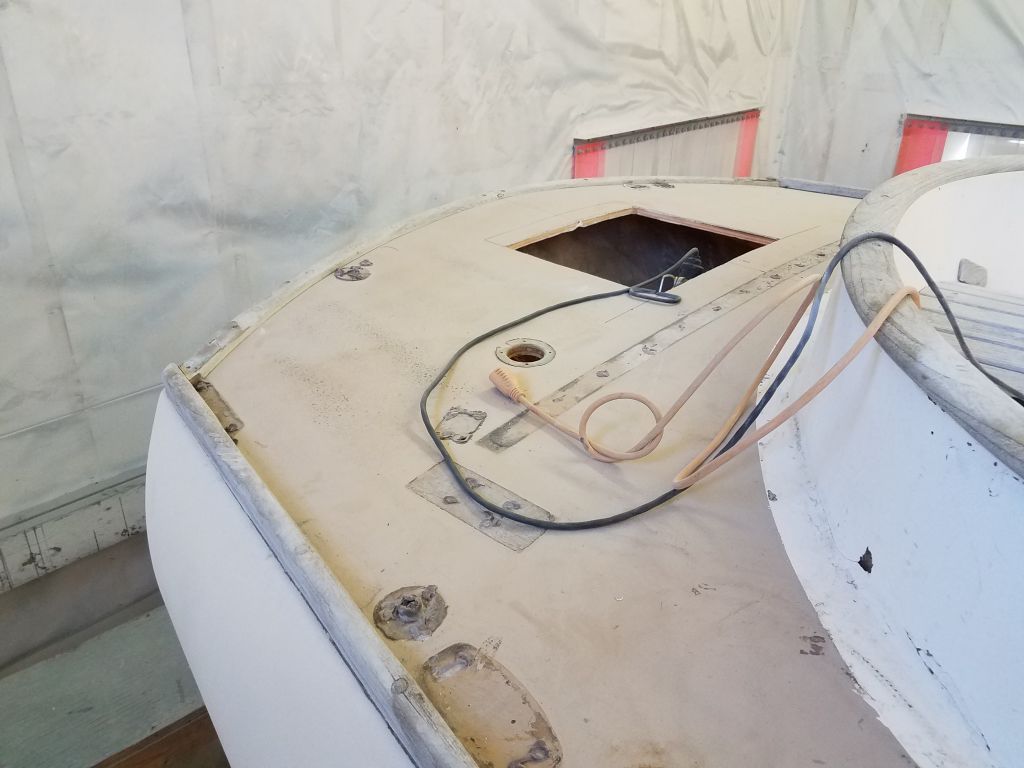
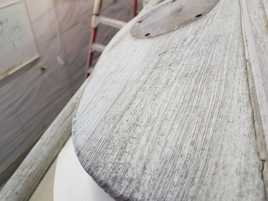
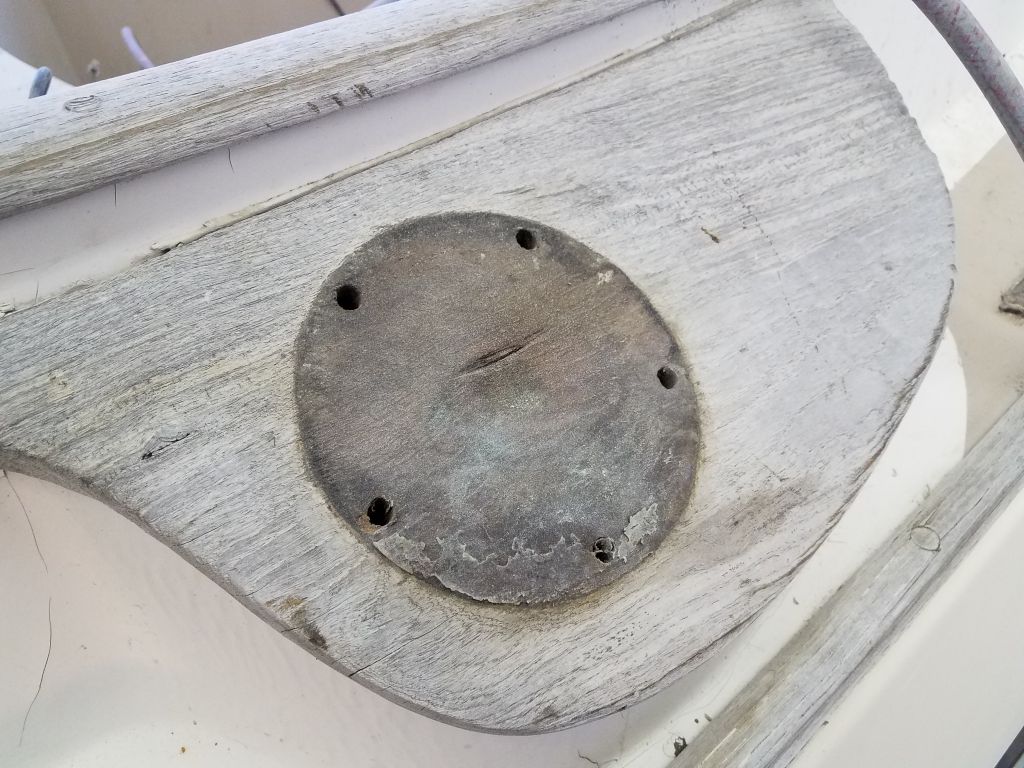
With plans to reinforce and glass over the hull/deck joint, there was now no question that I needed to remove the bowsprit. I’d postponed this for various reasons, but never truly thought it would end up staying in place–there were always too many reasons to remove it, even if the existing platform was re-used. I proceeded carefully to as to save the platform without damage. With things about to get dirty and nasty in the shop with some major deck work ahead, now seemed the best time to take care of this removal.
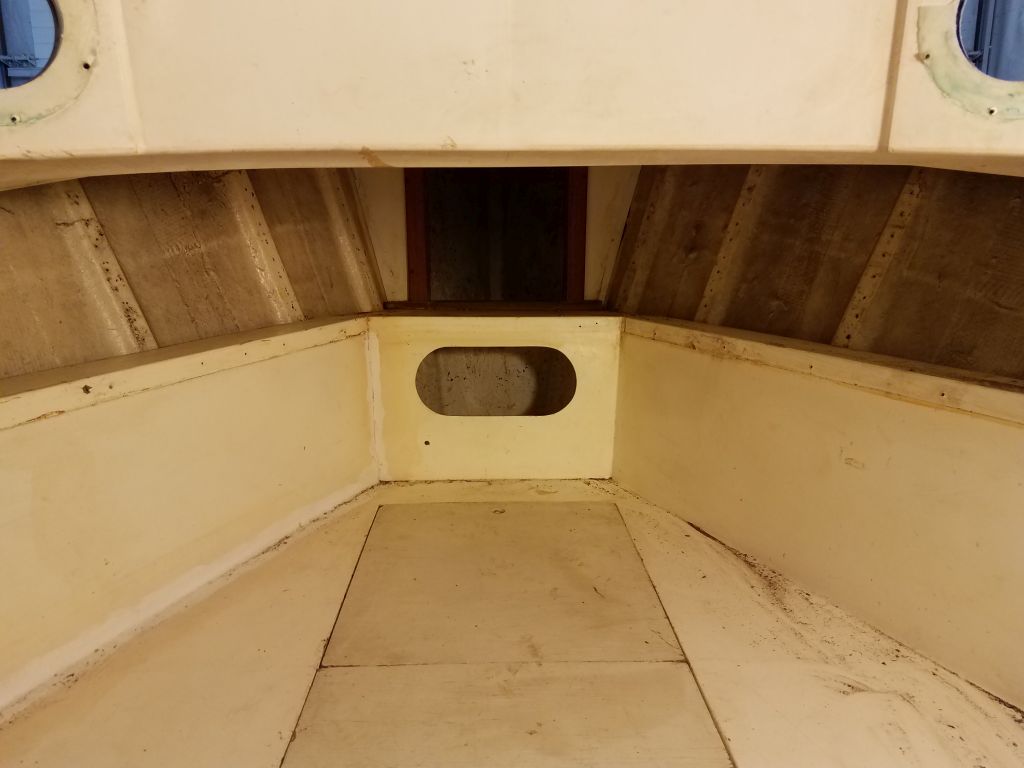
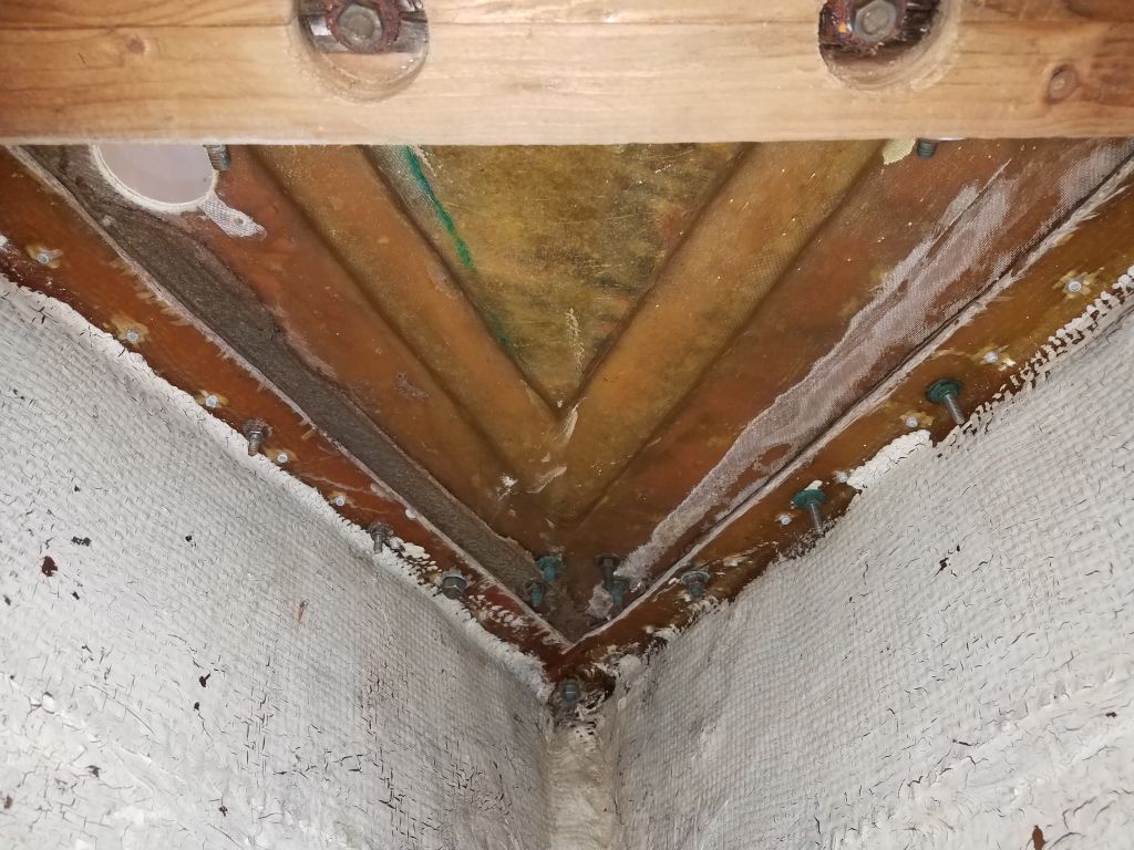
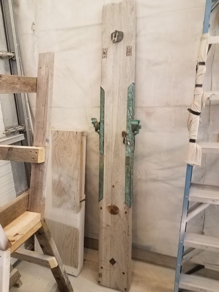
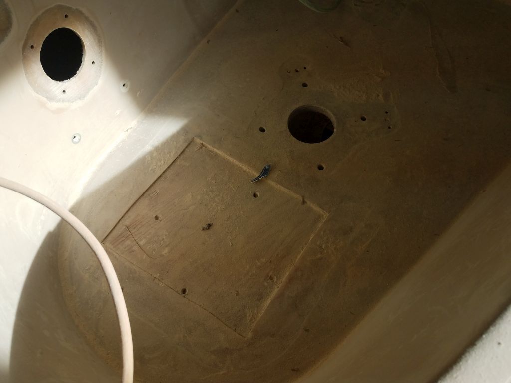
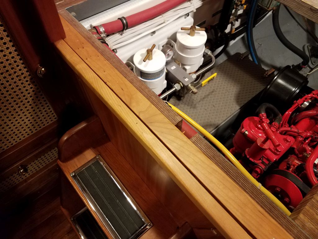
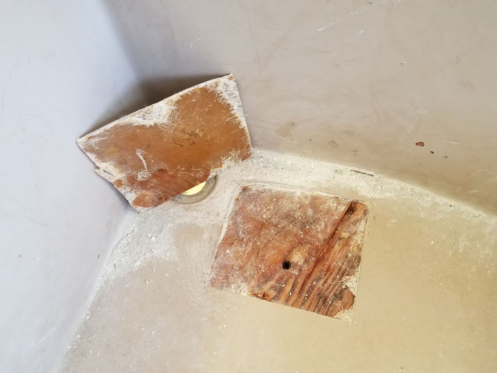
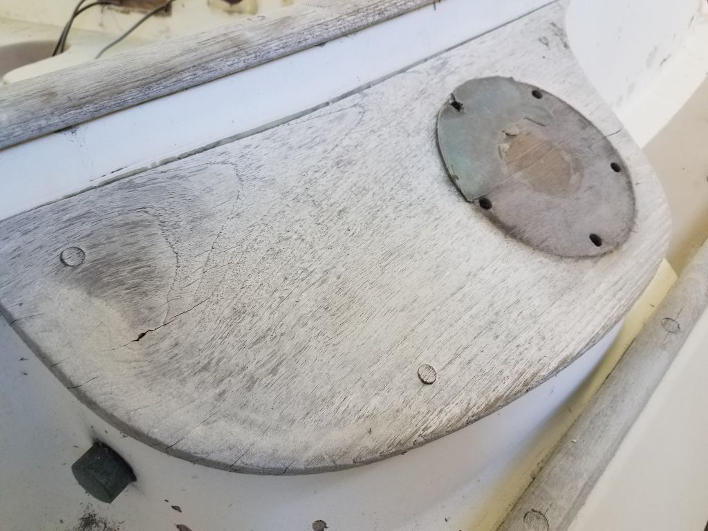
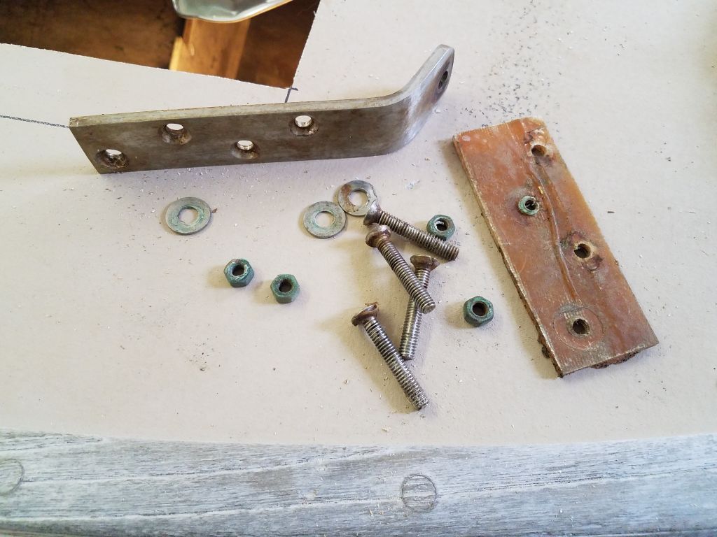
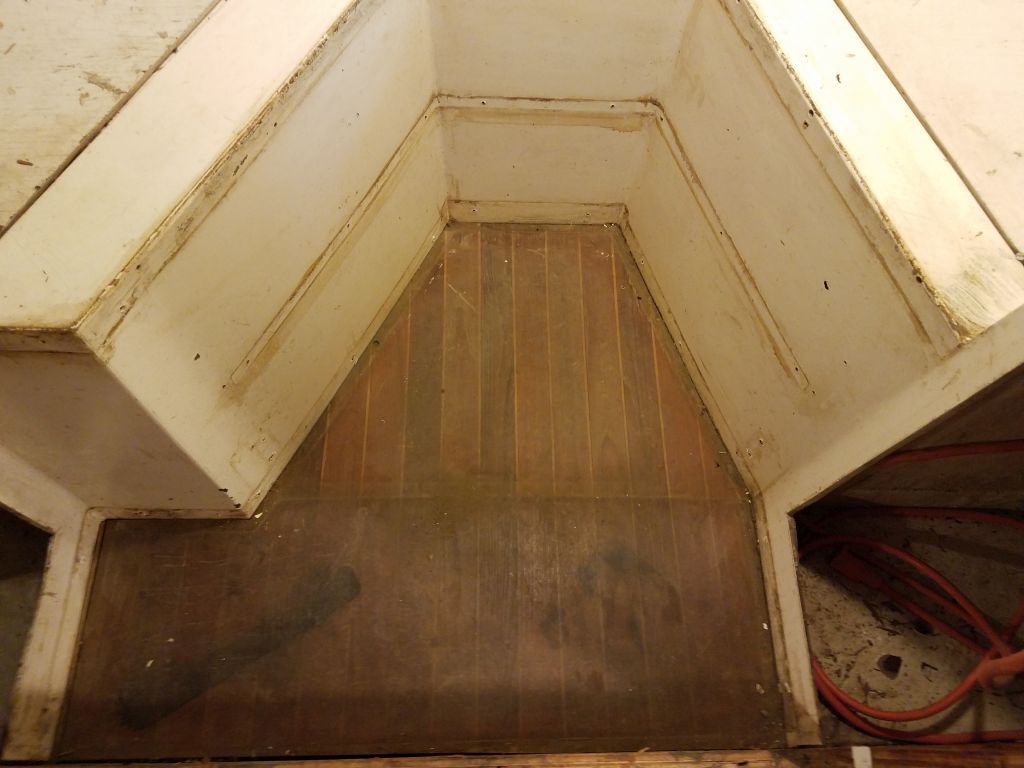
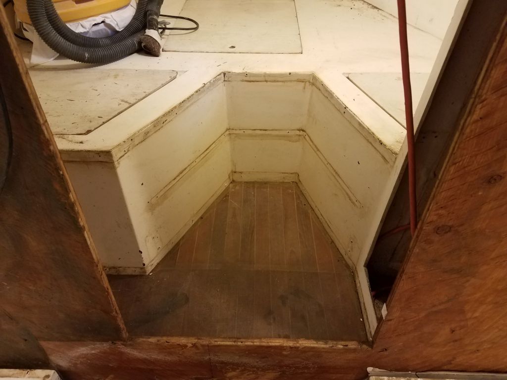
The platform was secured through the foredeck with 11 bronze carriage bolts, including four through the inner forestay attachment point. Even before removal, I could see a thick bed of silicone sealant beneath the platform that promised to make removal challenging. Access to the bolts from the chainlocker was tight, as the opening into the chainlocker was not only small, but awkwardly placed thanks to a stepped section in the cabin liner that incorporated a little storage bin.
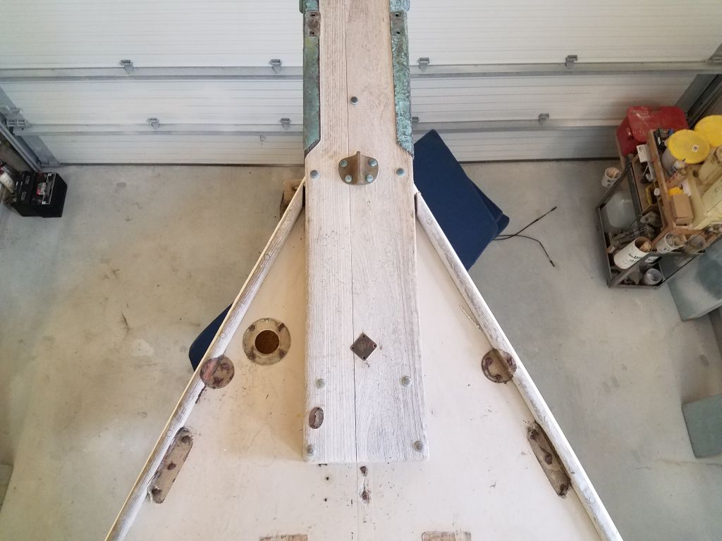
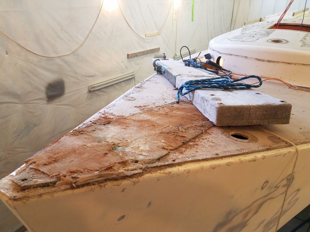
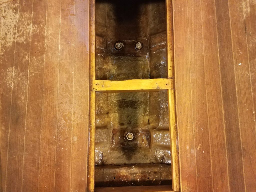
I removed all the nuts I could from belowdecks and hammered up the bolts so I could reach them from above, but the configuration of the access simply didn’t allow me the reach I needed for the forwardmost bolts. Fortunately, the way the bare platform had weathered over the years meant that the carriage bolt heads stood a bit proud of the adjacent surface, so I could easily cut the heads off with a saw without affecting the surrounding wood. Once I had all the nuts removed and/or heads cut off, I removed or pushed the studs back down through the holes and into the boat to free up the platform, other than the sealant.
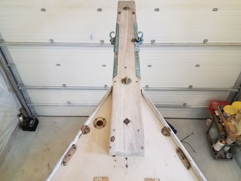
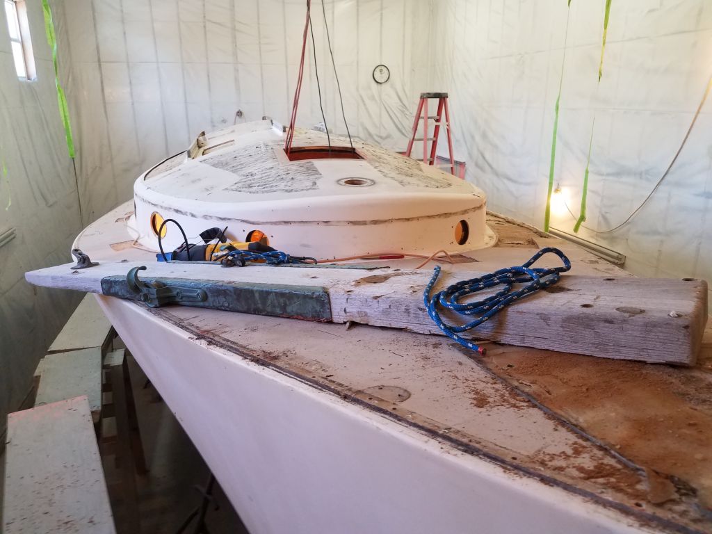
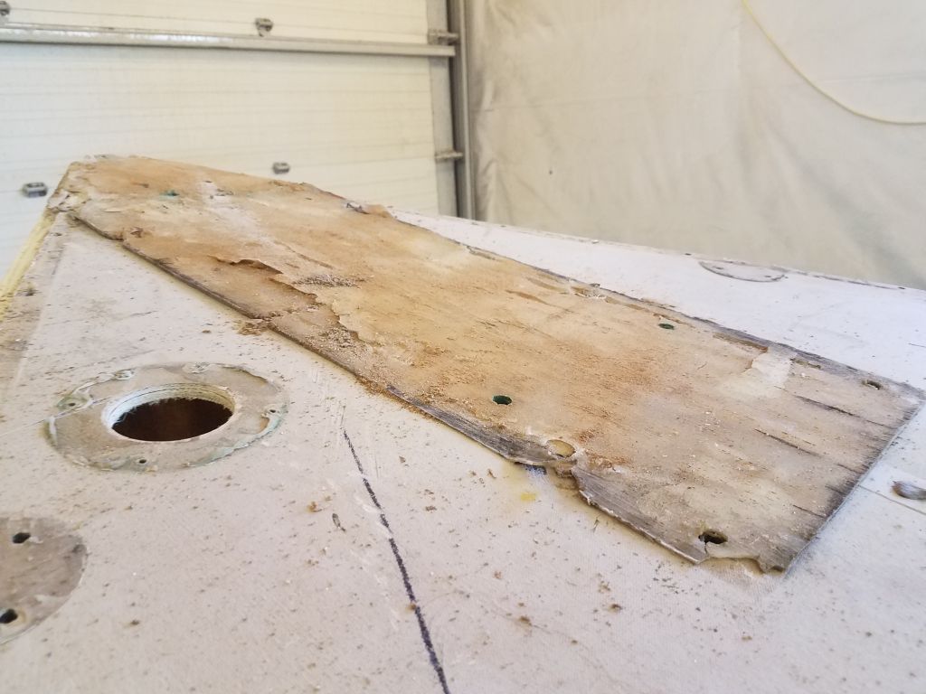
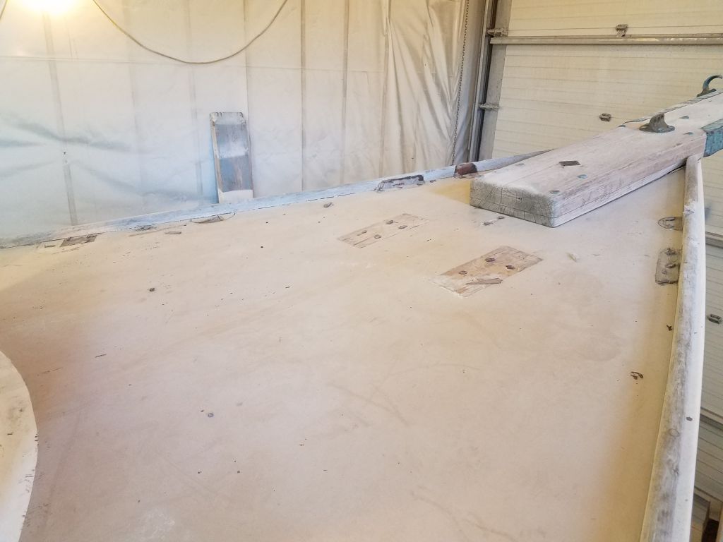
Freeing the platform, which extended over the deck by several feet, all of which was heavily bedded in the silicone, was quite a chore, particularly while being conscious of keeping the platform intact. In increments I eventually managed to slowly pry up the platform, first from one side, then the other, and finally drove a chisel all the way beneath it near the stem, which helped finally start breaking the grip of the highly flexible, thick layer of rubber. To prevent the platform, which extended further outboard of the boat than over the deck, from pivoting off uncontrollably when I finally cut the last of the silicone, I ran a small line through the aftermost pair of bolt holes and tied the platform to the boat. Once I finally freed the platform, I could spin it around so it rested on the deck so I could regroup and then lower it down to the shop floor.
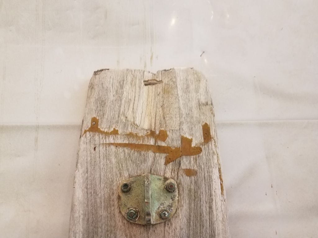
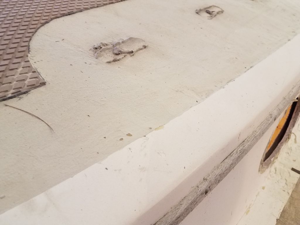
The platform was in basically good condition, with some damage at the outermost end on the underside, but heavily weathered. For now I could leave it be, as it would be some time before I needed to reinstall it.
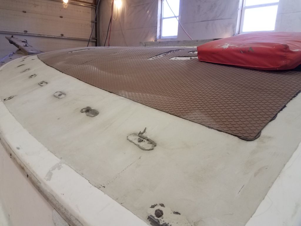
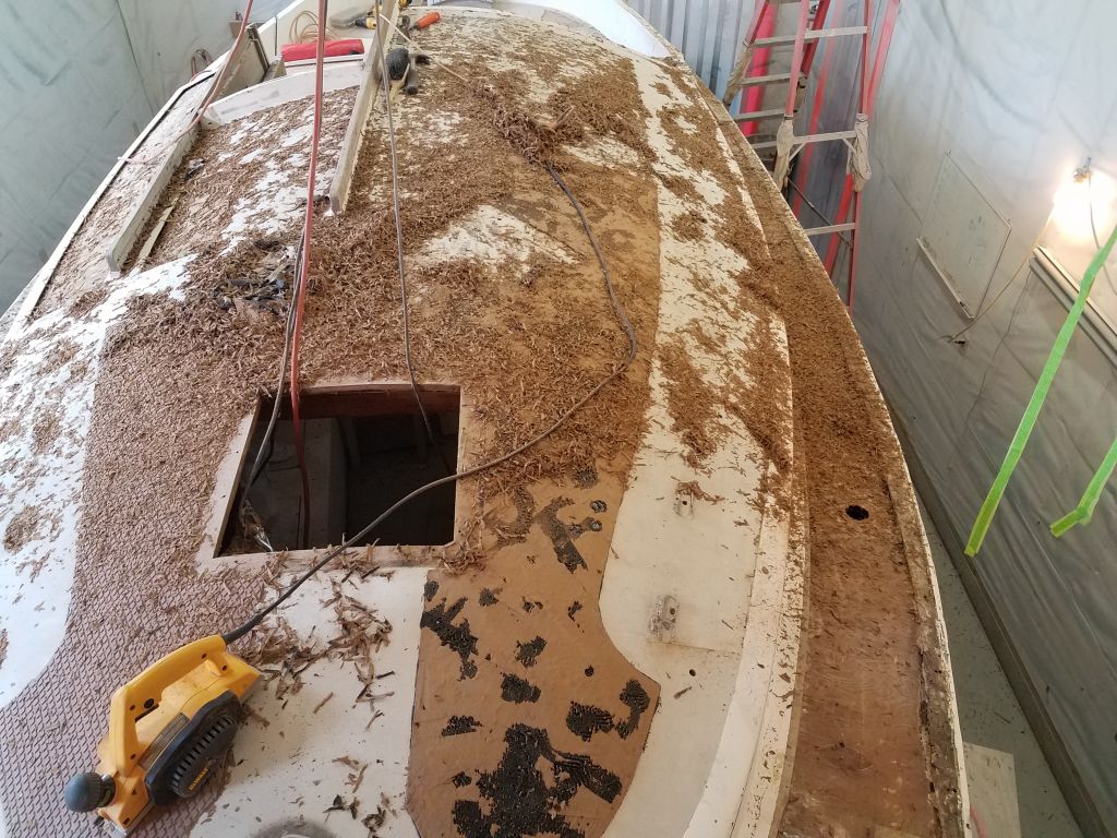
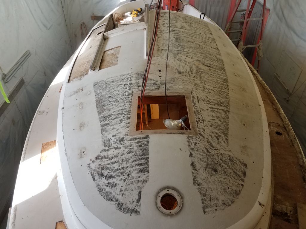
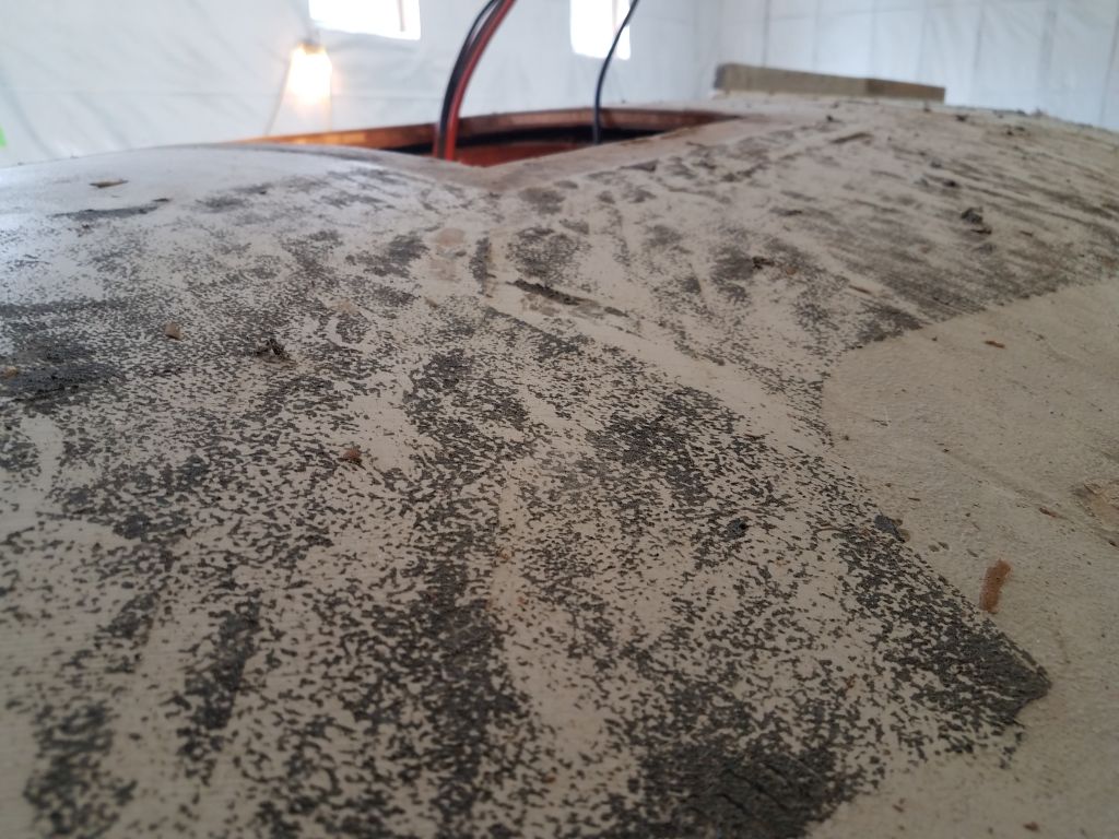
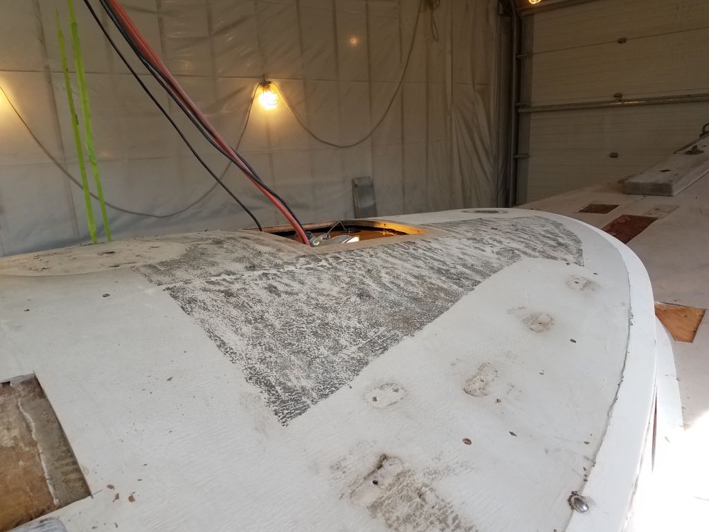
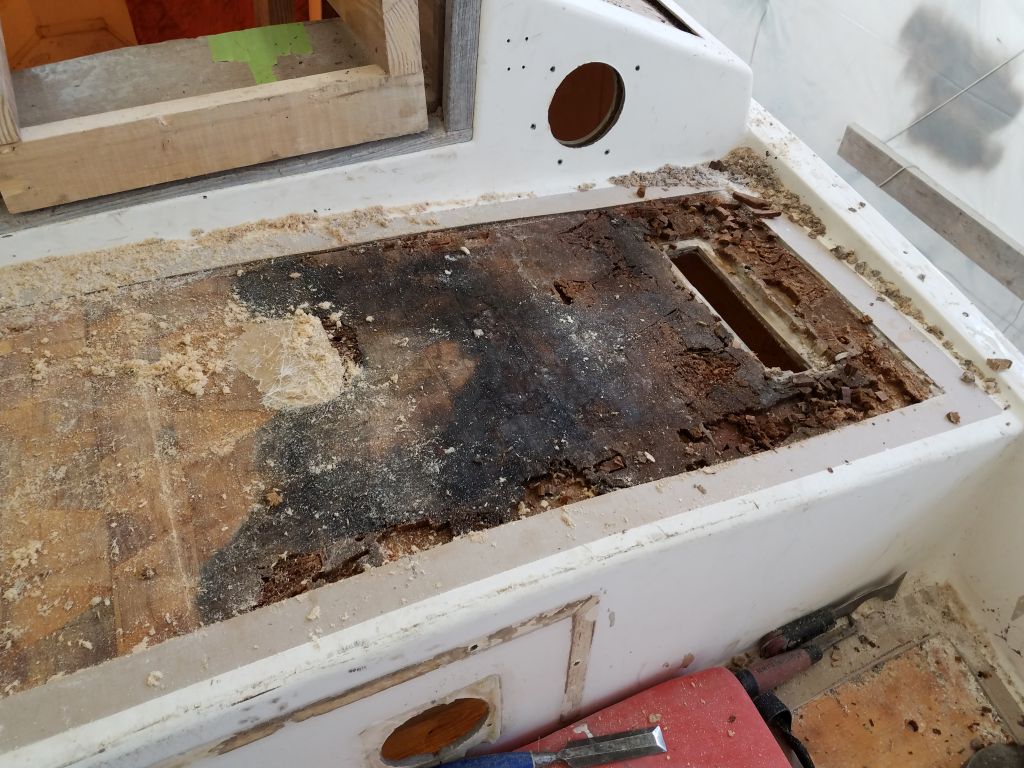
With a chisel, and then a paint scraper, I removed the bulk of the old silicone from the foredeck. The layer was about 3/16″ thick over most of the deck.
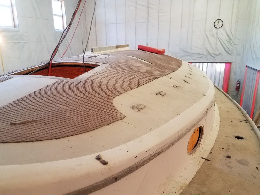
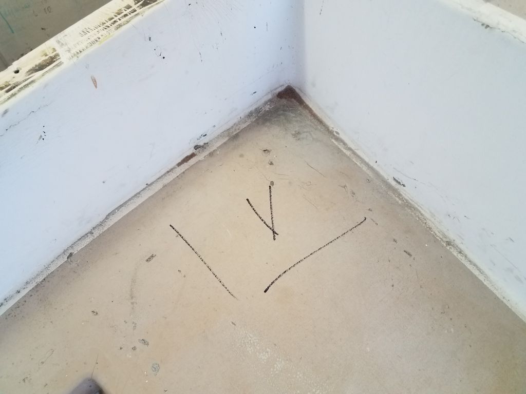
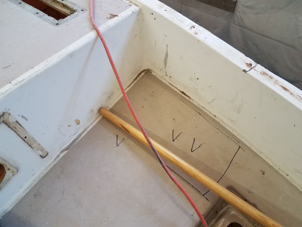
Preparing for several days of heavy sanding work ahead, I made some reference marks on the hull and deck on either side of the gunwale to indicate how far to remove paint or gelcoat for the hull/deck reinforcement.
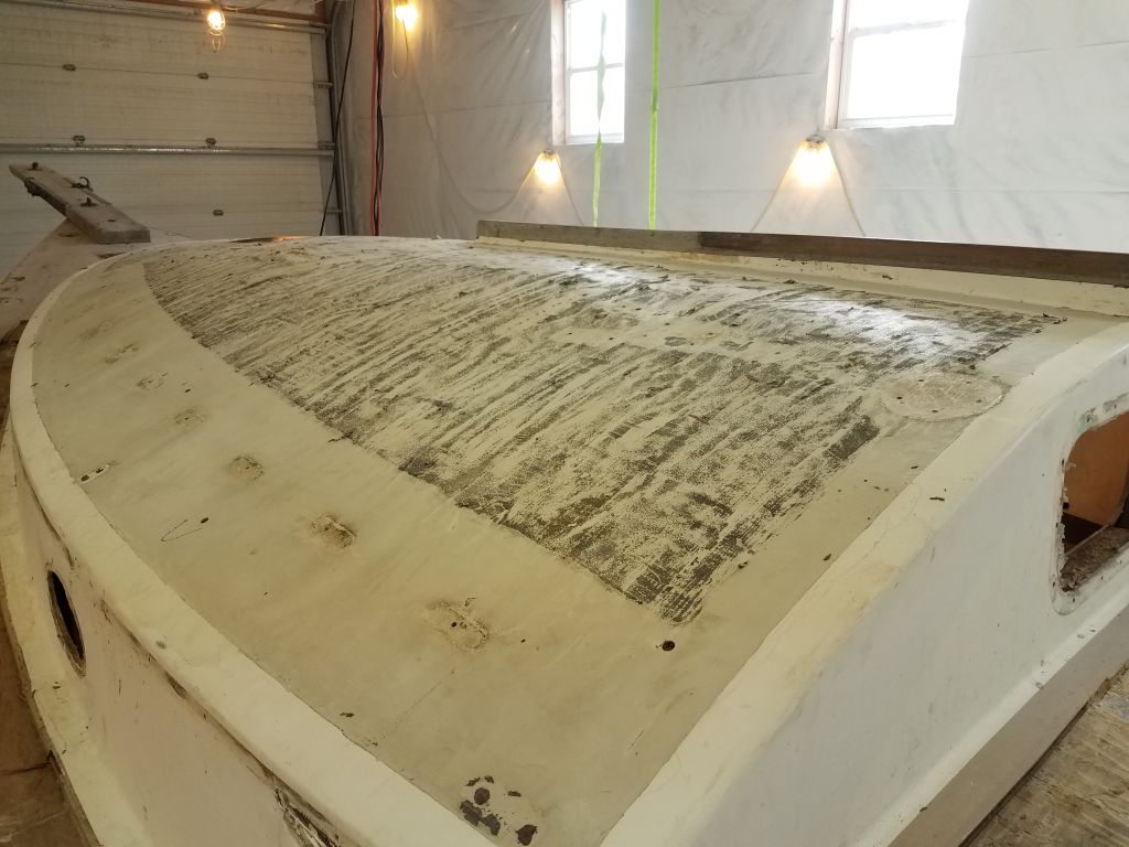
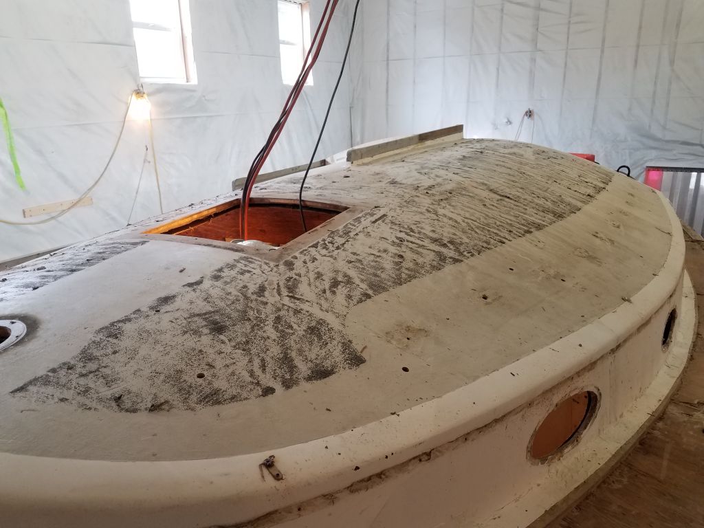
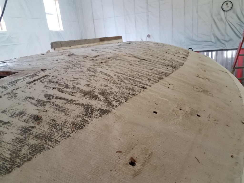
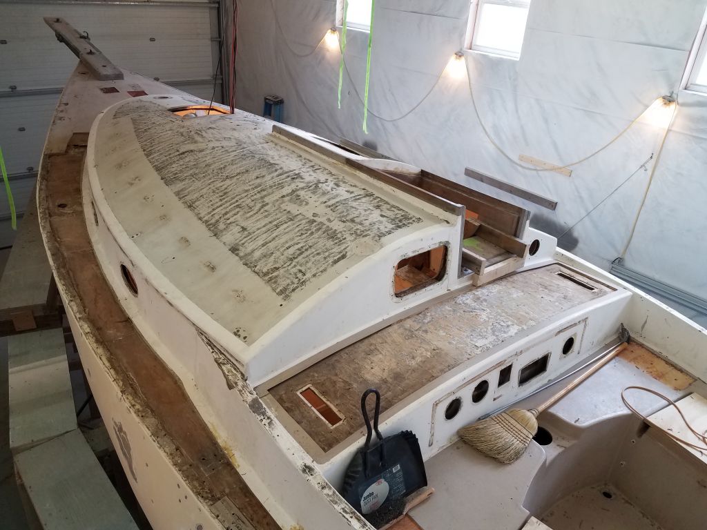
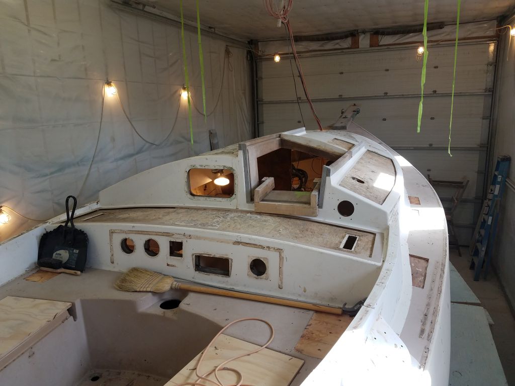
During the remainder of the day, I used a grinder to prepare the edges of all the areas to be recored and relaminated, removing gelcoat and creating a slightly tapered raw fiberglass edge over which the new work would eventually bond and tie in the repairs with the existing structure. I also cleaned up the inner deck skins and top of the original plywood core as needed. In this session, I completed the work on the starboard coachroof, bridgedeck, cockpit, starboard sidedeck, starboard foredeck, and poop deck., leaving the port sidedeck and other areas for next time.
Total time billed on this job today: 6.5 hours
0600 Weather Observation: 28°, foggy. Forecast for the day: Becoming partly sunny, around 40°
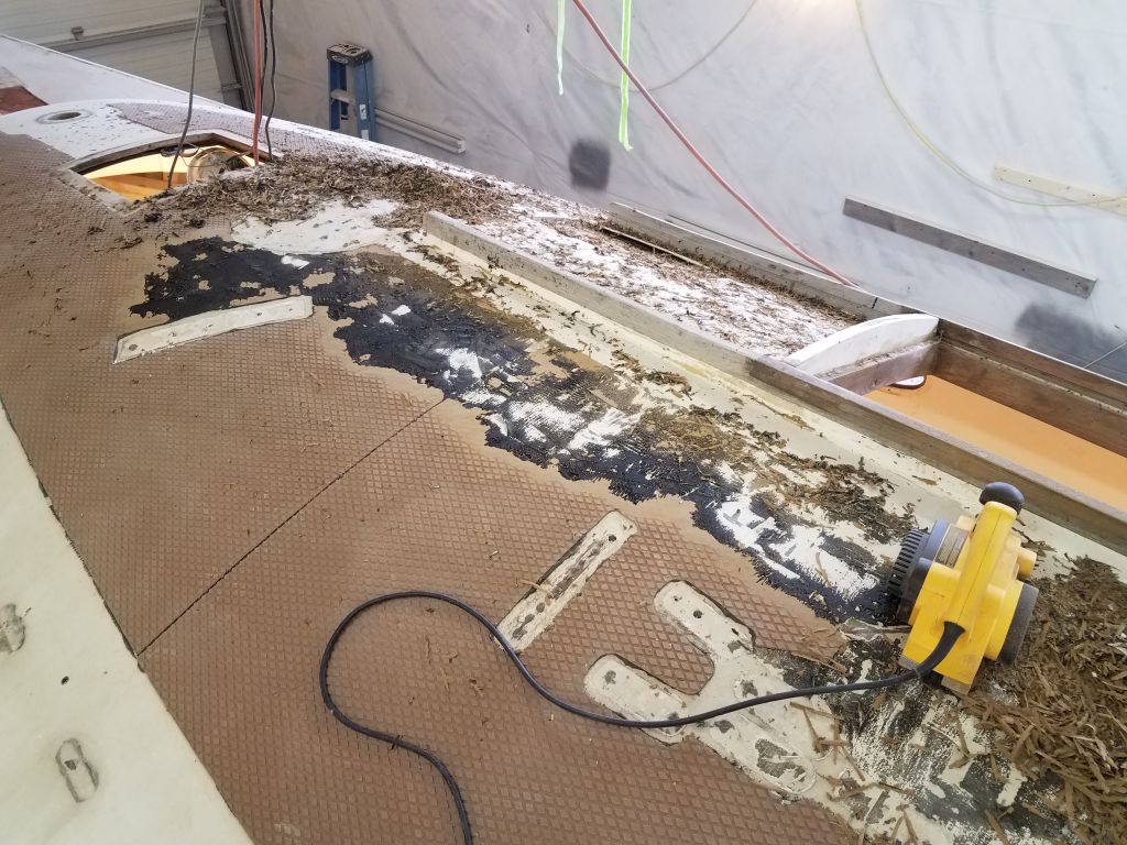
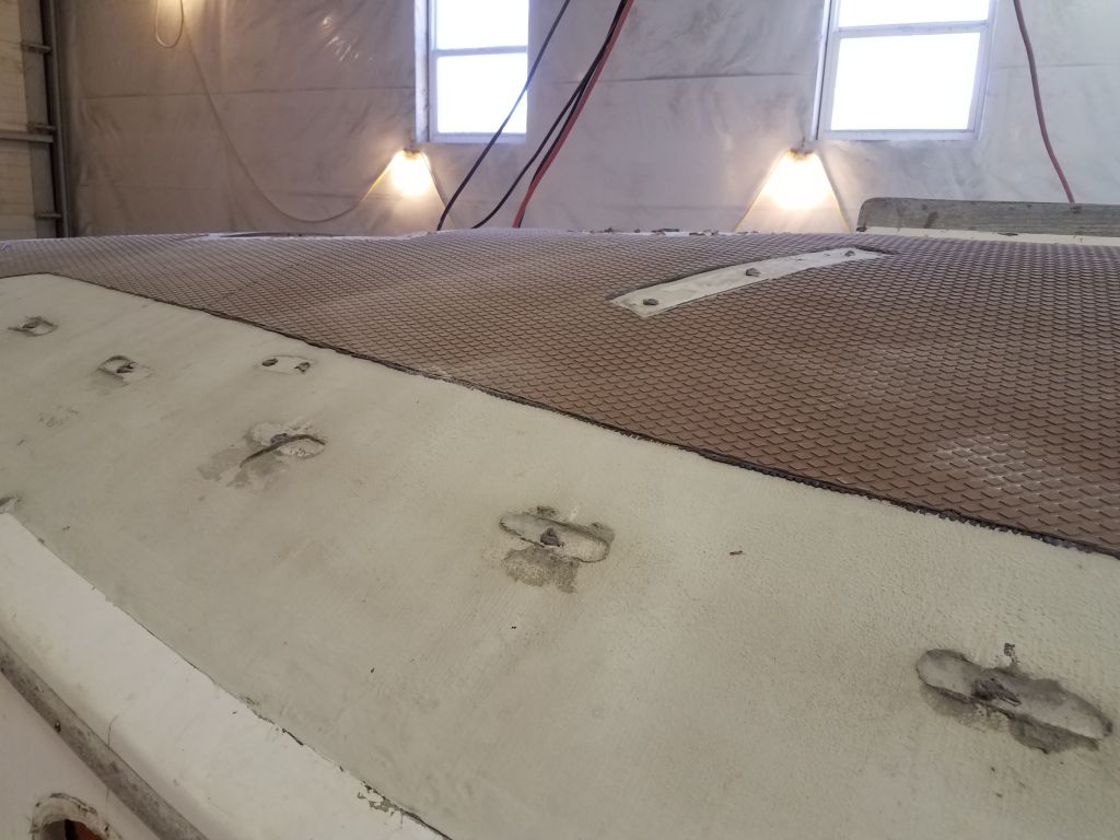
The sharply curved coachroof was mostly covered with Treadmaster nonskid, a flexible sheet product with an aggressive pattern. The installation in this case was rather rough, with pieced-together sections and lack of attention to detail. In order to continue with the deck repairs and deck refinishing, I needed to remove this, not only because its appearance was poor, but the deck beneath–which had been repaired at some earlier time–was extremely roughly finished and uneven, and required additional work and refairing.
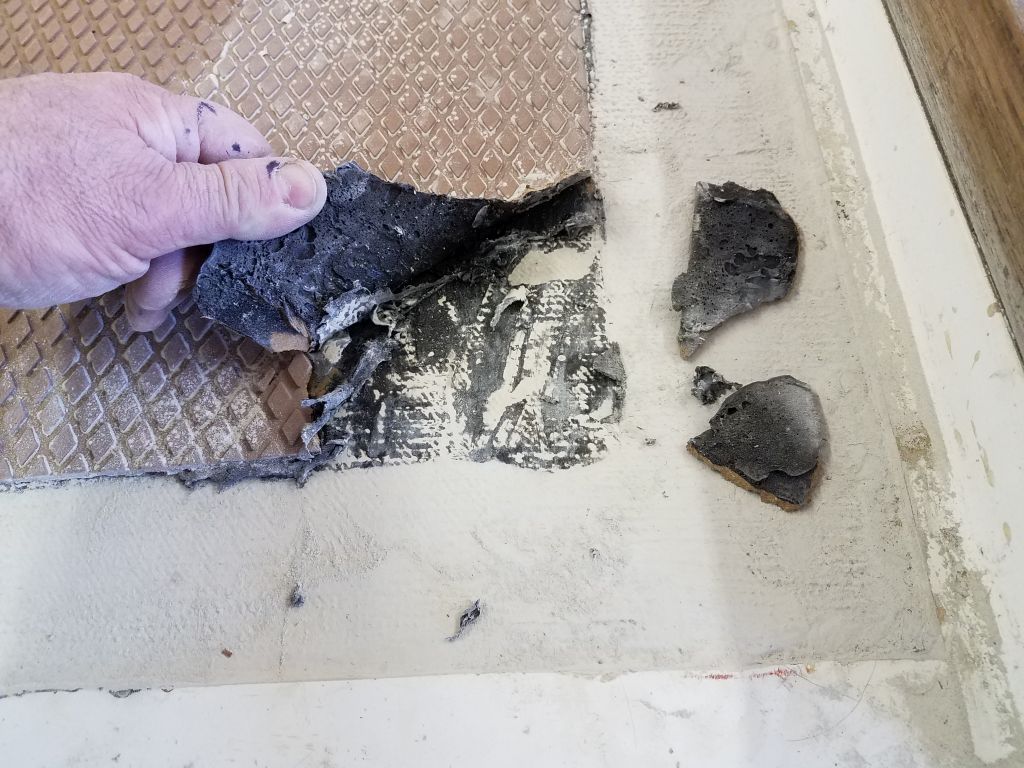
The nonskid sheets appeared to be installed with a flexible adhesive rather than epoxy or similarly aggressive adhesive, and this promised to make removal relatively possible, if unalterably tedious. During an earlier removal test, I’d found the Treadmaster relatively easy to scrape free with a chisel, but this was slow.
To get started, I tried the chisel method at the aft end of the coachroof, and made some progress, but I just couldn’t see doing the whole area (at this point it looked like a sports field in size) with a 1″ chisel. The adhesive, whatever it was (I thought probably a polysulfide) was not that aggressive, but was still resilient and flexible and, while at least possible to remove (unlike something like 5200 or epoxy), it wasn’t exactly a breeze either.
In an earlier project, I’d had pretty good success using a power planer to remove the Treadmaster. I’d held off trying it here because I had some dim memory of my planer being inoperable, though I couldn’t remember why, but I soon found that I’d been stymied changing the blades the last time (this was in 2010) because of a recalcitrant fastener holding one of the blades in place. Apparently I’d put the planer away and never used it since. Now, though, I discovered that I’d apparently purchased replacement parts for the screws at issue, so I was eventually able to use semi-destructive means to remove the fastener (I used a Dremel tool to cut a slot for a screwdriver, since the Allen screw head was stripped), after which I could complete the blade replacement with the new parts that I’d ordered before.
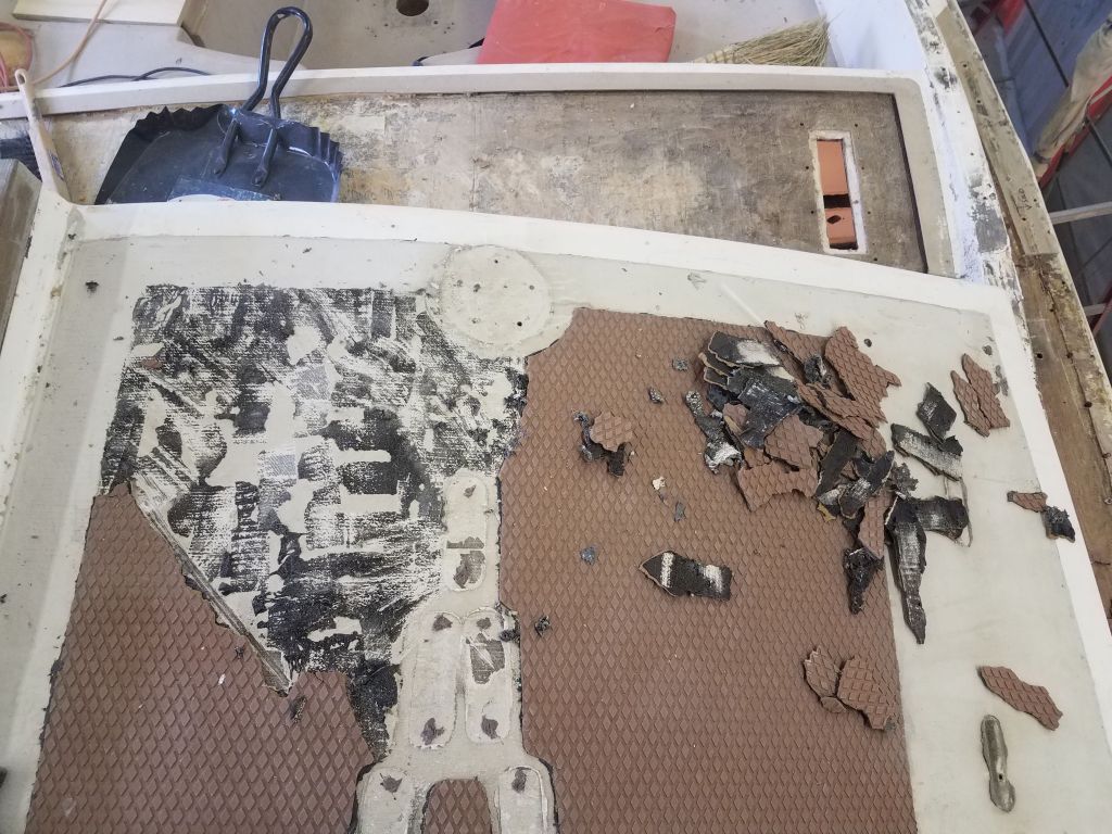
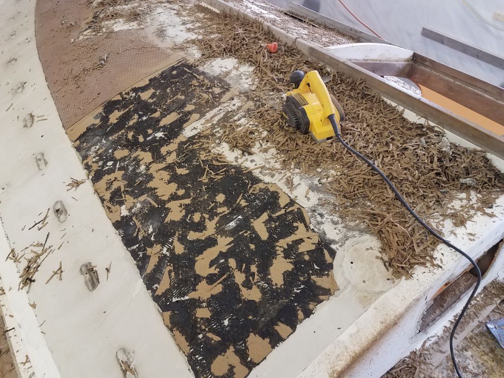
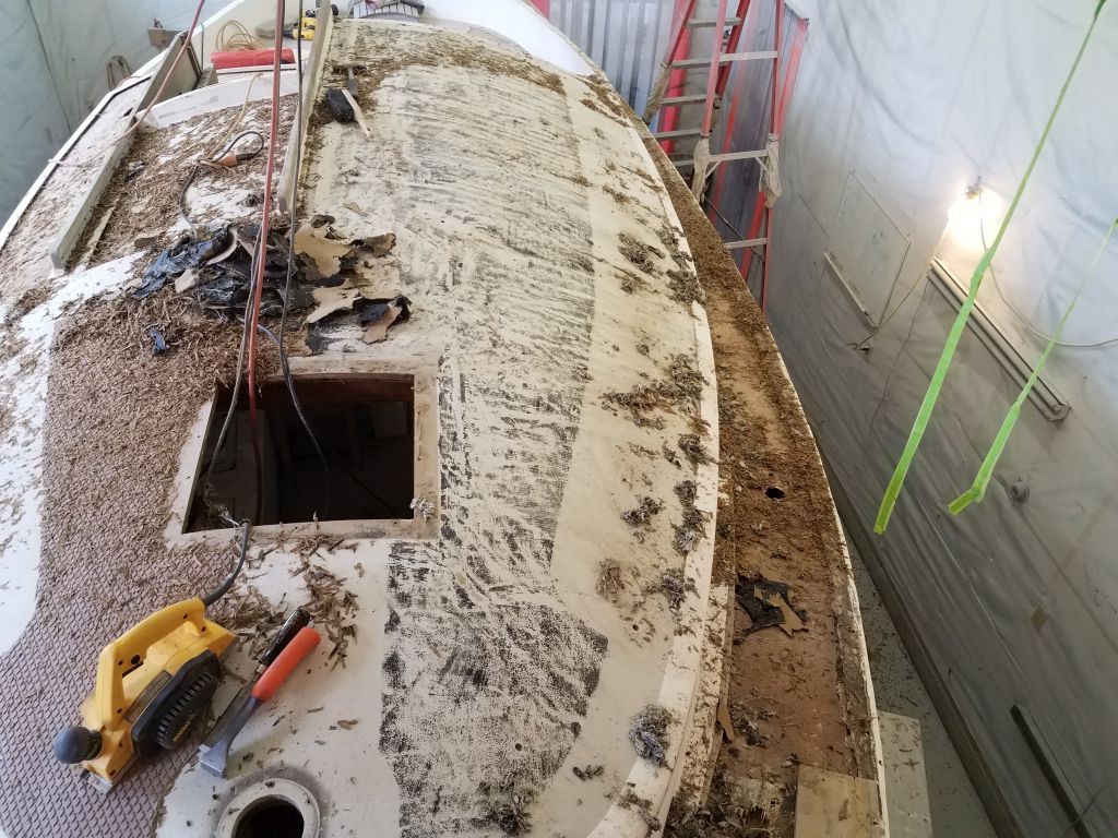
The planer worked quite well. Fortunately in this case the deck was all convex and wide open making it easier for the flat base of the planer to work; it doesn’t do so well on tight spaces and with different curvatures. This removed the bulk of the Treadmaster easily and pretty quickly, generating huge piles of debris. Once I got down to the flexible adhesive, I I found I couldn’t really use the planer any more, as the base bound on the rubbery surface and didn’t really allow planer movement, though the blades would cut through it if I could keep the planer moving.
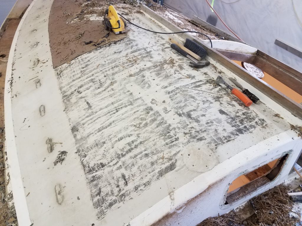
To remove the rest of the adhesive, I turned to my 1″ chisel (I tried a larger one but it wasn’t as effective), and hand-scraped the bulk of the adhesive (which, thanks to the undulations in the deck beneath, was quite thick in many areas) and thin remnants of the nonskid material, much of which came off in stretchy sheets. This left just a bit of residue behind which I cleaned off with a carbide paint scraper, leaving a surface that I could finish up another time with a sander. The scraping steps were plenty of work, but it wasn’t that difficult to remove the adhesive cleanly.
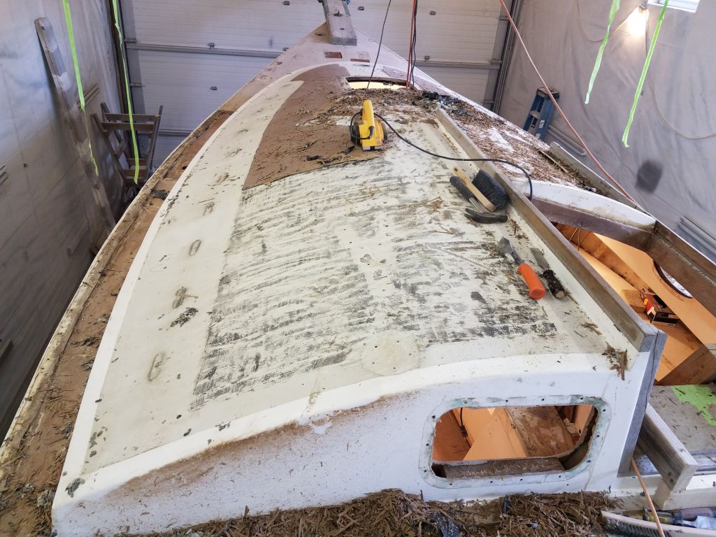
In this three-step manner, I continued for the remainder of the day, eventually removing all the Treadmaster and virtually filling a large garbage can with the spoils. The planer blades were pretty dull by the end, but still managed to do the job I needed them to do, if a bit more slowly. I found as I went on that it was easier to leave a thin skim of the Treadmaster rather than fight through the top layer of adhesive, with no noticeable increase in difficulty for the scraping steps afterwards.
The deck beneath would require plenty of additional work to properly fair and finish, but despite that the glasswork had seemed sound throughout the process.
Total time billed on this job today: 7.25 hours
0600 Weather Observation: 18°, clear. Forecast for the day: Sun, with increasing clouds and chance of snow or rain showers later, around 40°
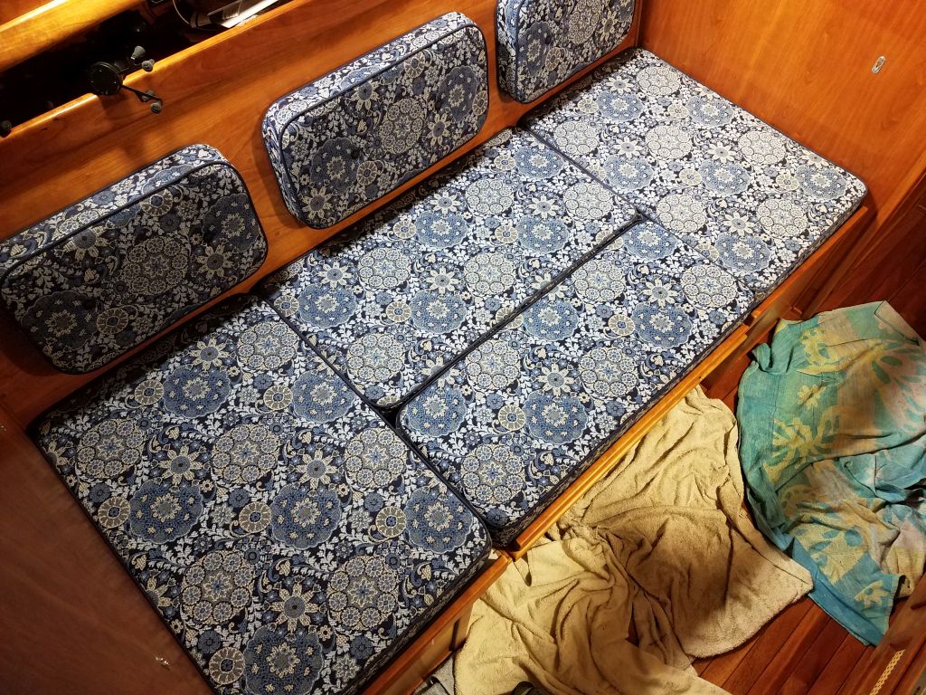
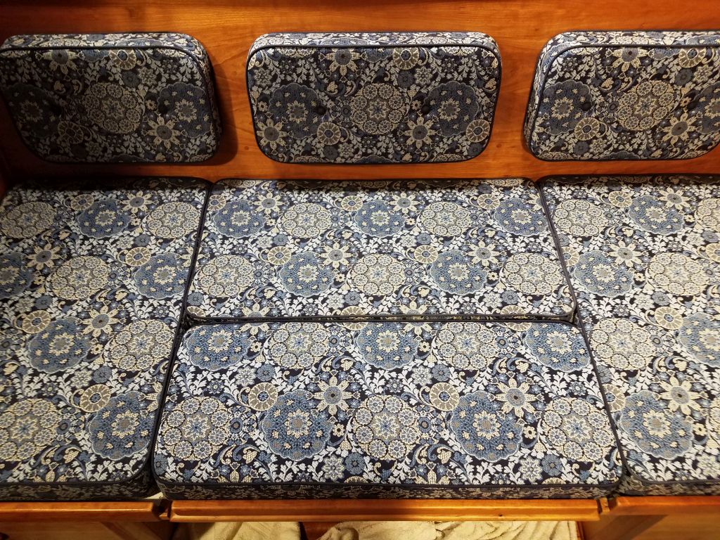
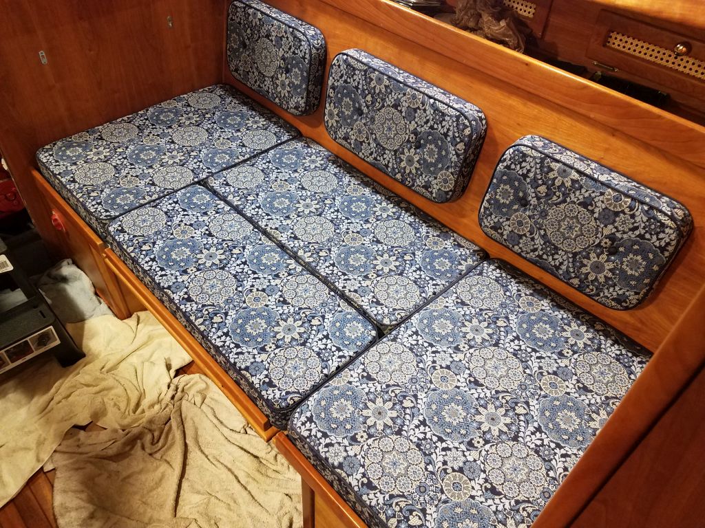
I had my trusted upholster make up a new filler cushion to fit in the required space, and with this now complete, along with the minor work I’d had to do on some of the trim pieces from last time, I made a quick trip to the boat to deliver the new cushion and finish up the installations.
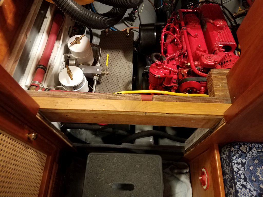
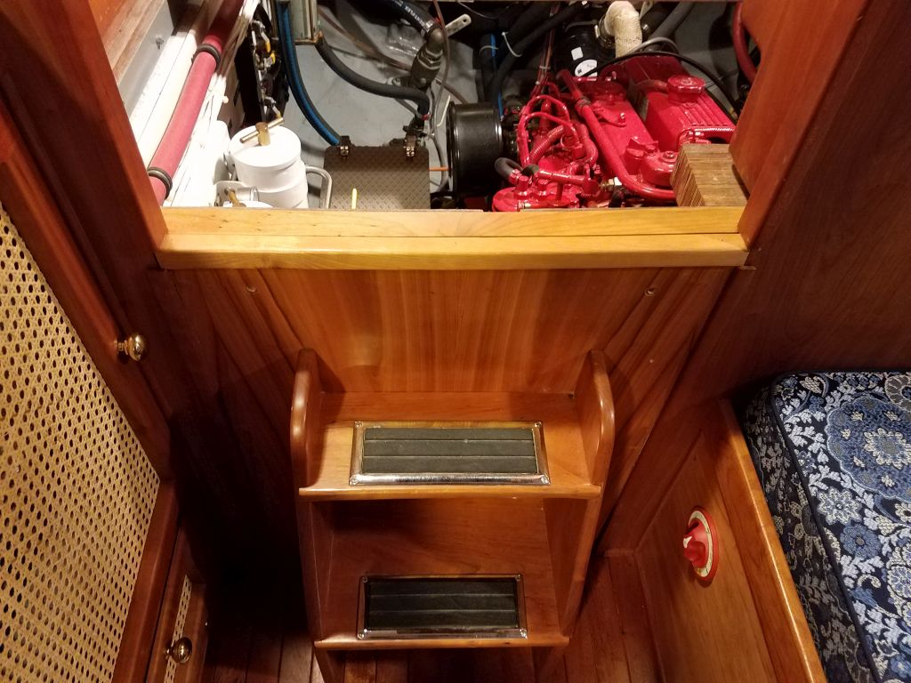
I also finished up the trim on the nearby companionway. When the ladder unit is properly secured with the four thumbscrews that attach it to the structure beneath, the seam between the trims would become tight; for these photos, I just placed the ladder assembly in place loosely.
0600 Weather Observation: 23°, clear. Forecast for the day: Sunny, 40°
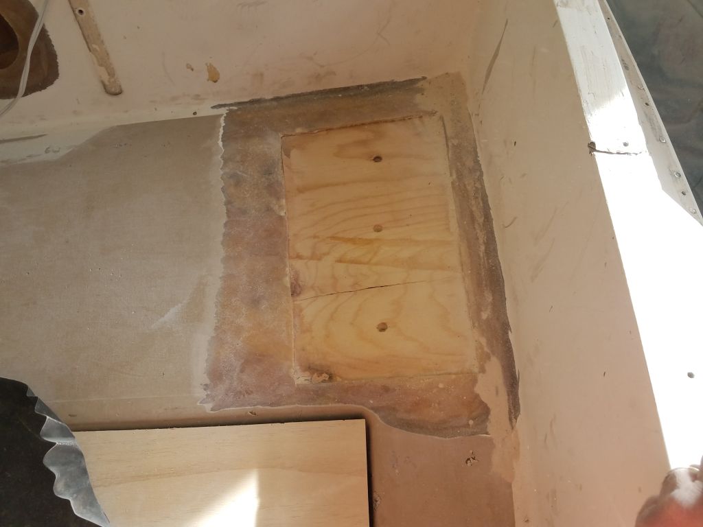
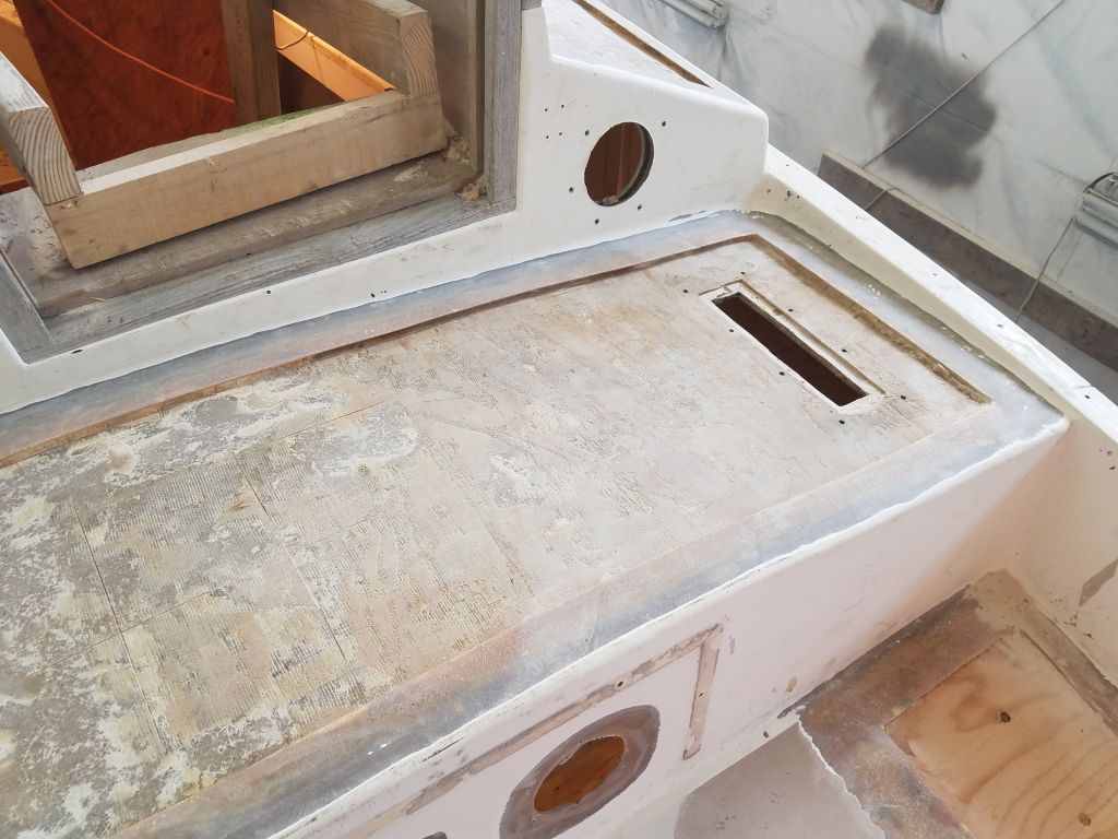
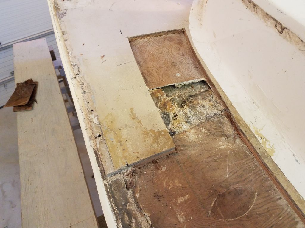
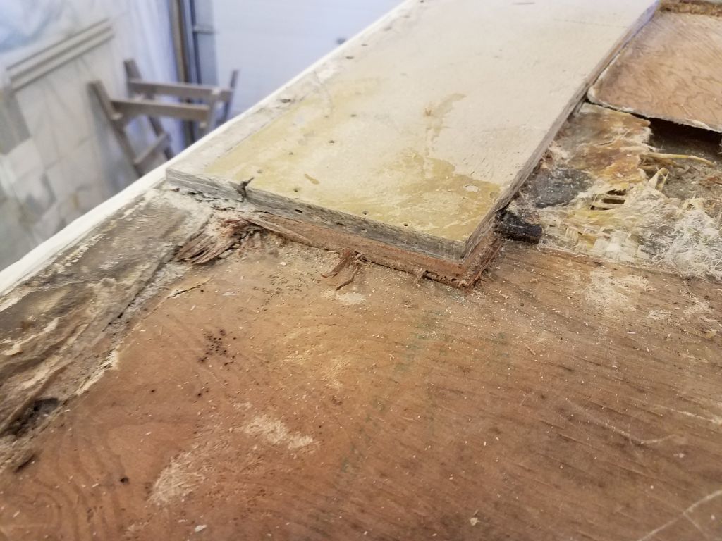
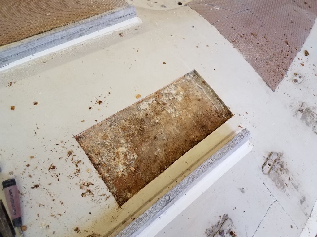
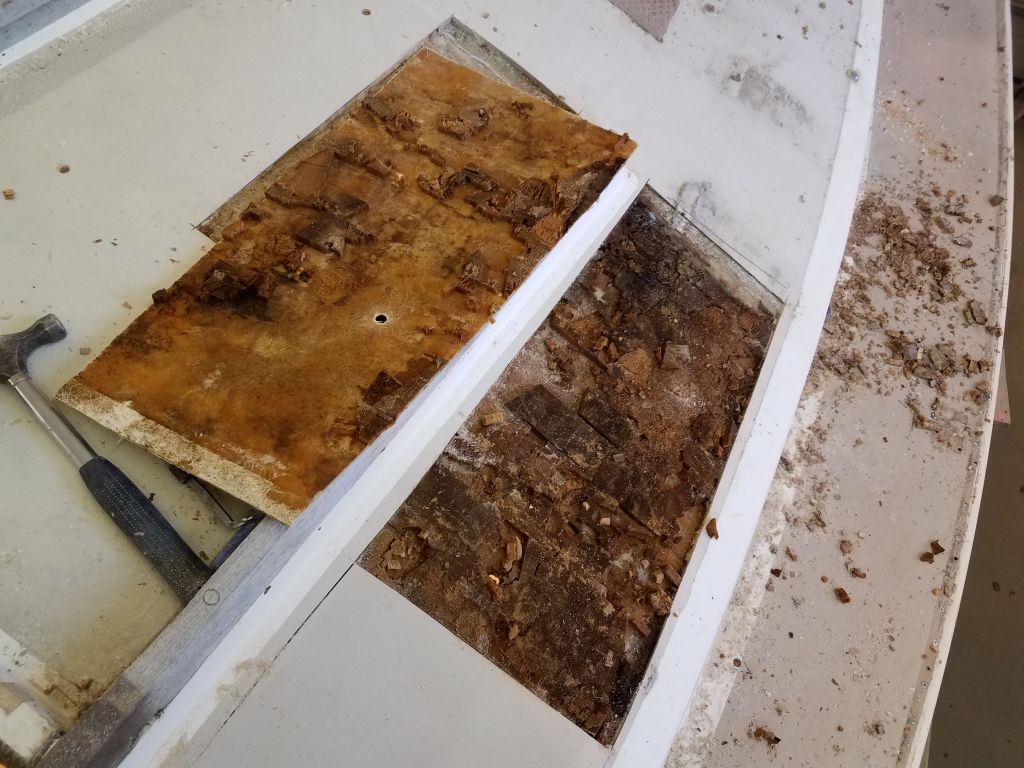
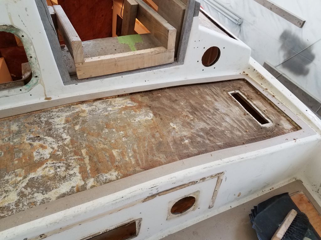
I wanted to extend the cutout on the port sidedeck a bit forward, into the original portion of the deck, to see what the transition area was like (between the previous repair and the original) and to better judge the condition of the coring immediately adjacent to the areas I’d removed before. In this area, I expected the core to stop well short of the deck edge roughly 7″ inboard, so I made my new cut accordingly.
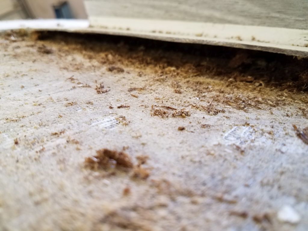
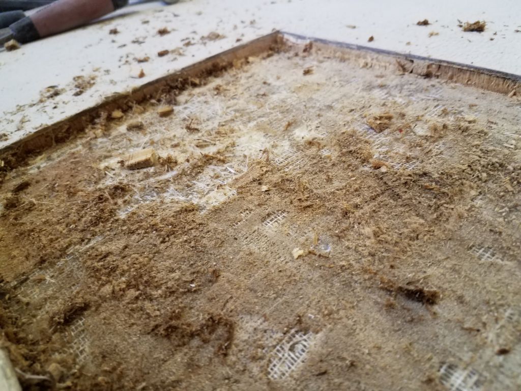
Here, at least, the top skin was still adhered to the plywood core, and by the forward end of the cut the core was showing less in the way of water damage. Removing the plywood from this section revealed the transitional area, which had previously been at least moderately reinforced from below, but I’d have to reconstruct the bottom skin over the existing area to better repair and strengthen the new work. I’d tie this all in with the adjacent deck and hull as well.
Moving to the starboard coachroof, I began by cutting open an area inside the companionway rails, leading aft from the section of the deck that had been rebuilt at some time in the past. My initial cuts were a bit shy of running into sound core on the aft and inboard sides, so I expanded the area a bit till clean, dry core bordered the entire cutout. As expected, the balsa core in this area was in poor condition. I intentionally extended my cut a bit forward into the newer work to help me judge the condition of that area as well.
I removed the old core from the cutout, reaming it out of the slot on the outboard side near the companionway rail as much as possible. The core in the adjacent section was a foam product, probably Divinicell, and the good news was that at least in this small visible area, the core and top skin looked sound, belying the rough outward appearance of the deck itself.
Next I cut the top deck skin outboard of the companionway on this side, removing the entire section. The core within was in extremely poor condition.
Again, I extended the cut an inch or two into the foam-cored section just forward, giving me another place to judge the condition and to better integrate the two areas during repairs.
I removed all the coring from the newly-opened area, scraped up the worst of the residue left behind, and cleaned out the edges below the adjacent deck flanges as much as possible. It’s worth noting that even given the poor and deteriorated condition of the balsa here, much of the saturated wood was more strongly adhered to the skins on either side (upper or lower) than the plywood on the port deck that I’d removed last time.
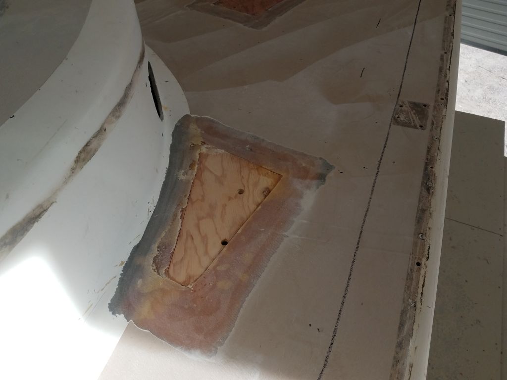
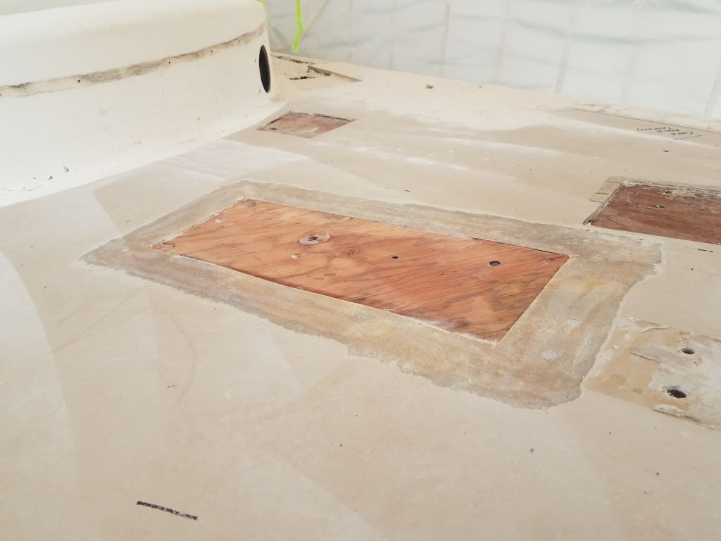
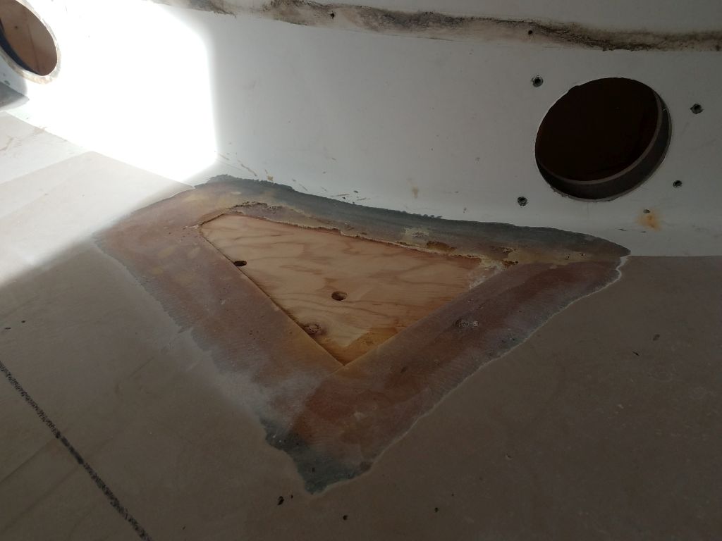
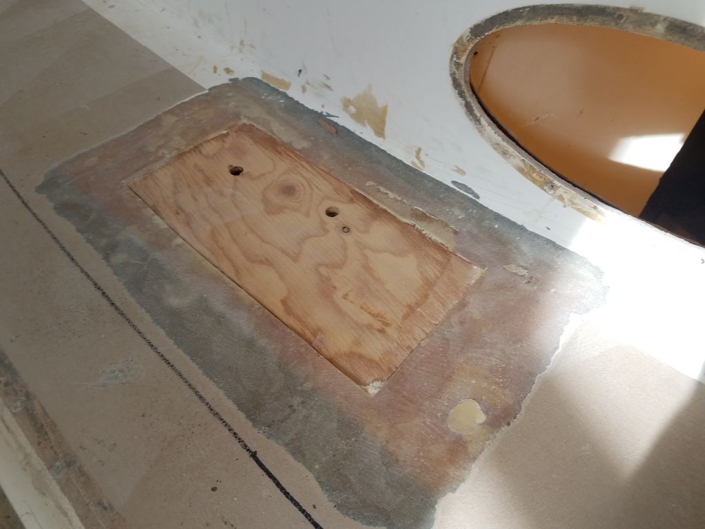
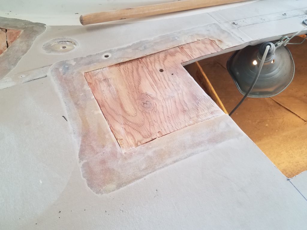
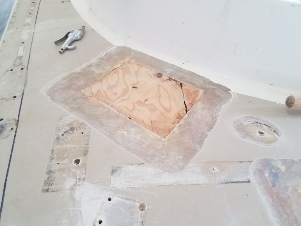
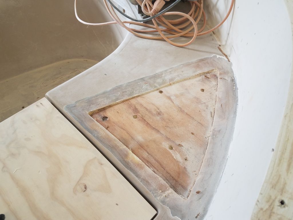
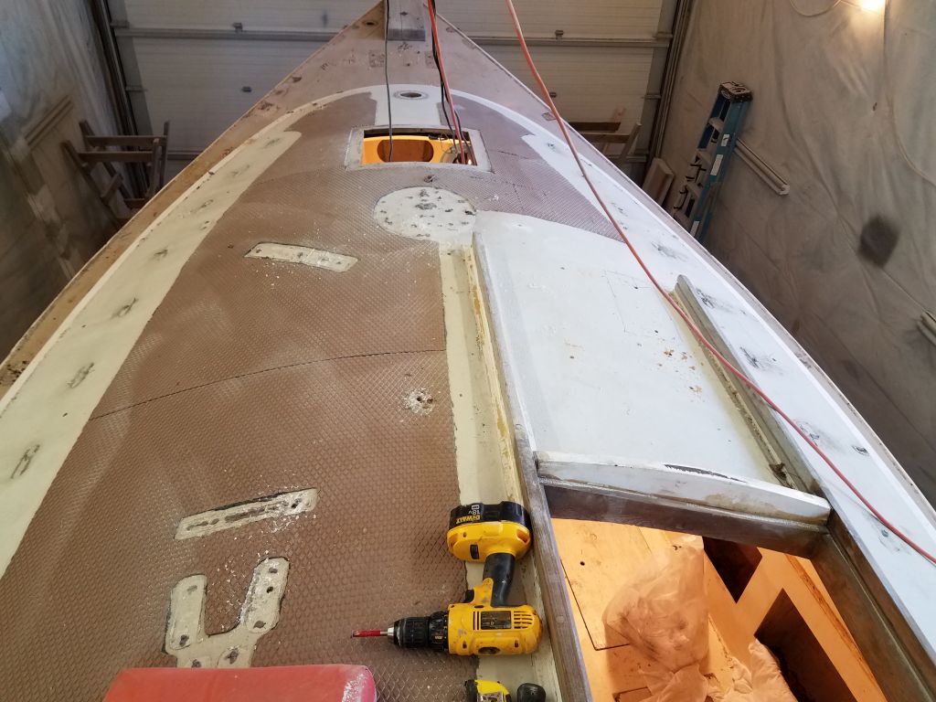
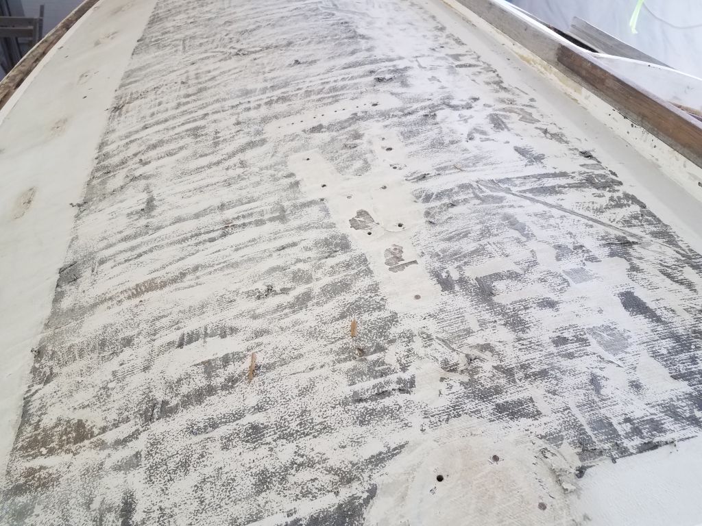
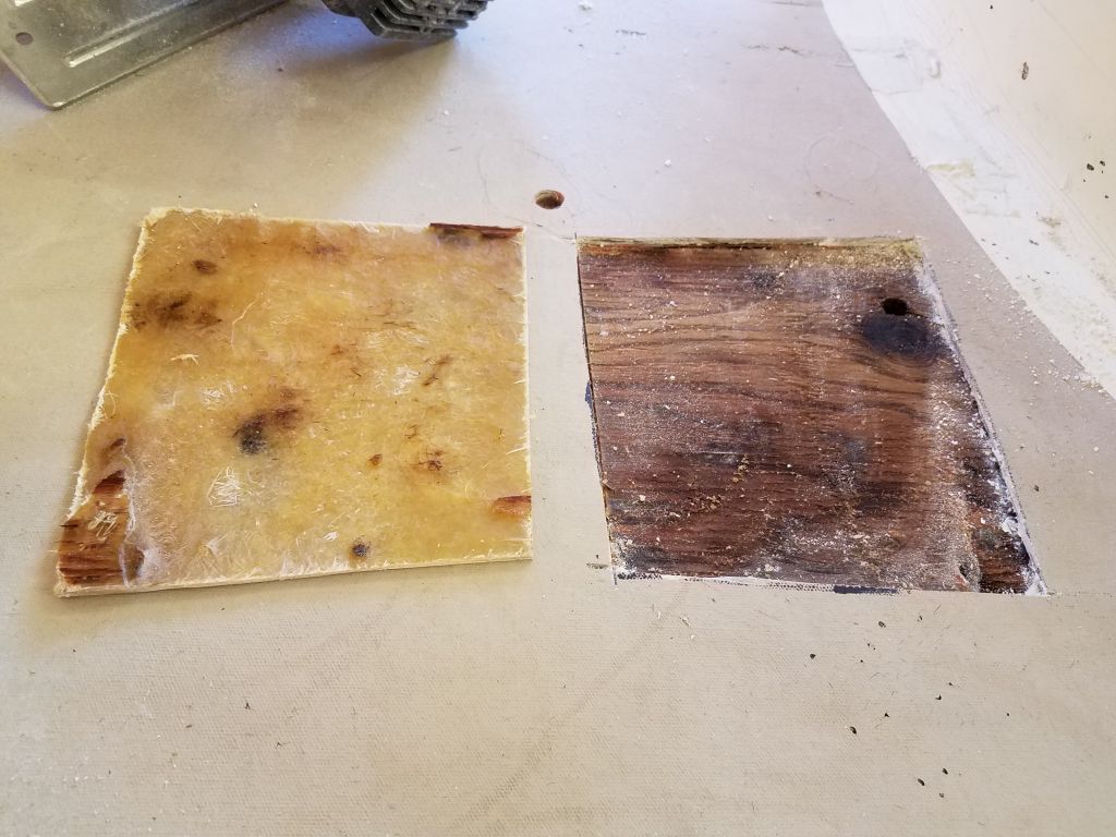
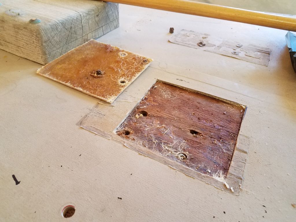
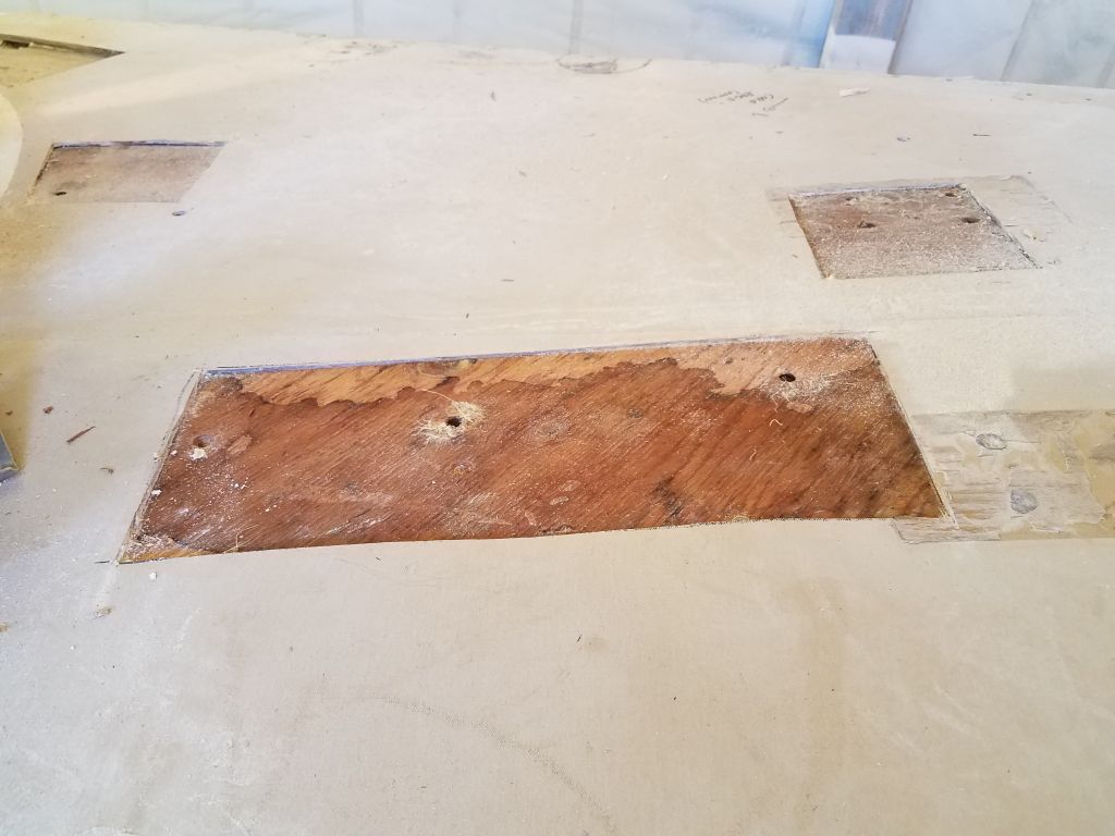
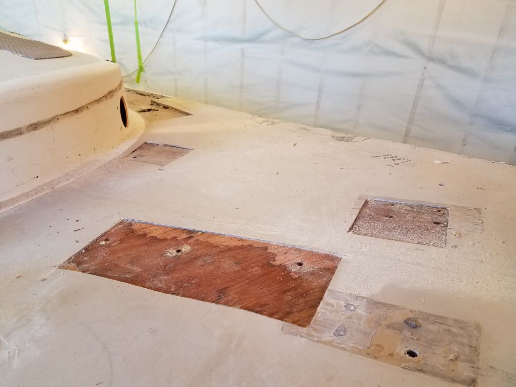
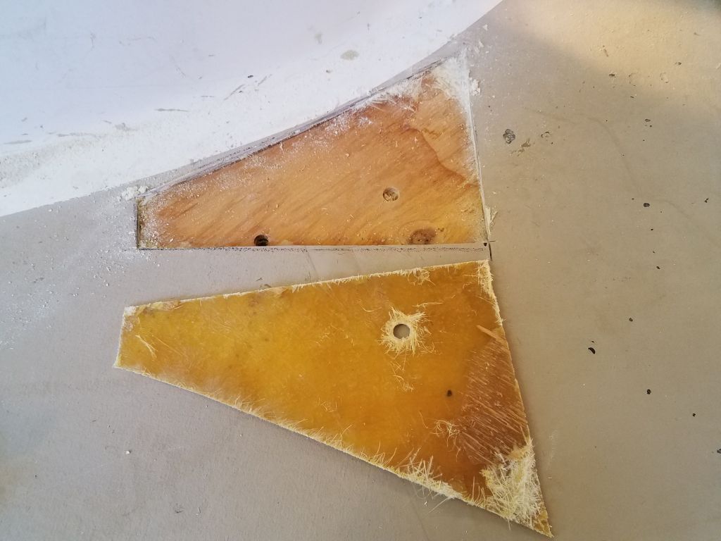
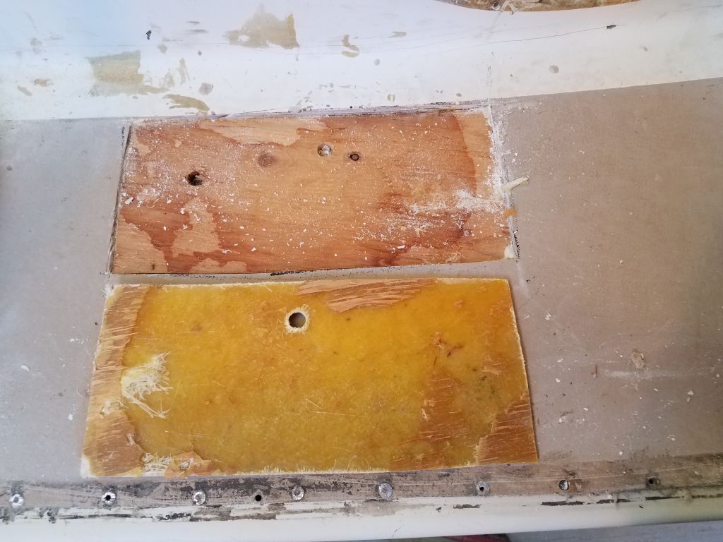
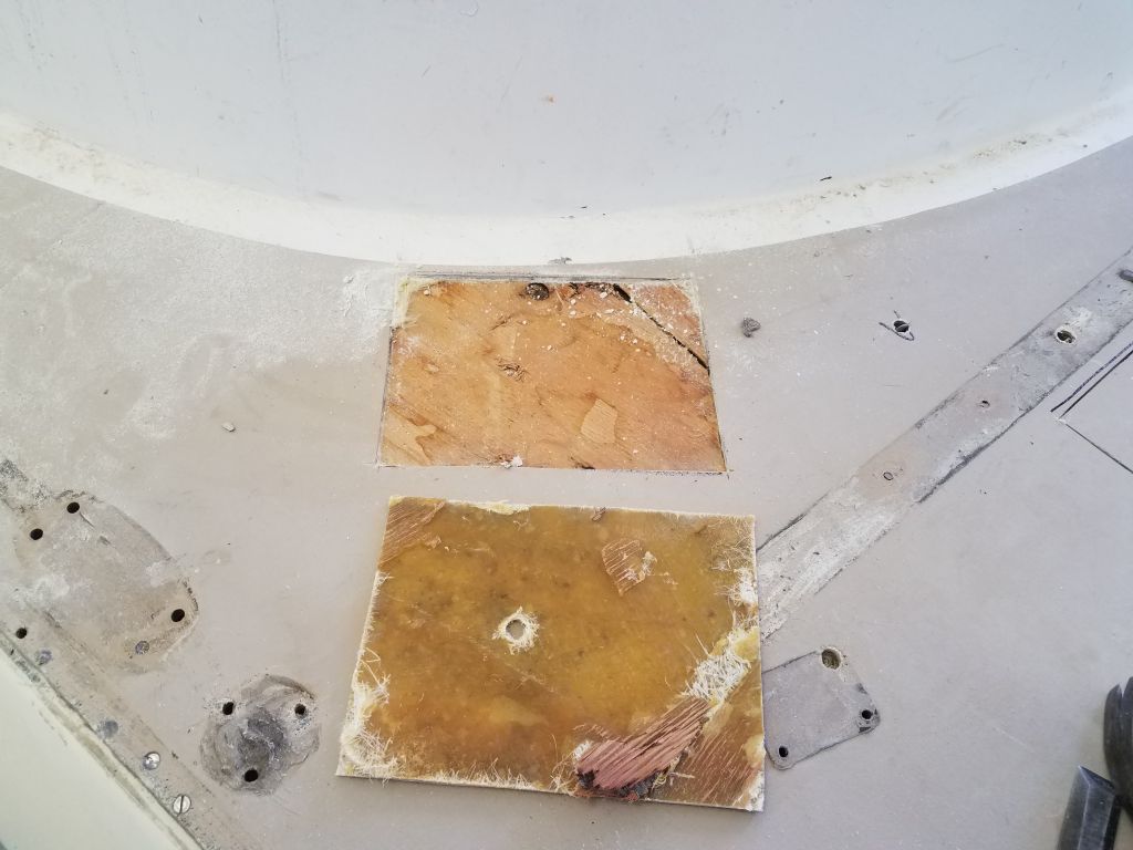
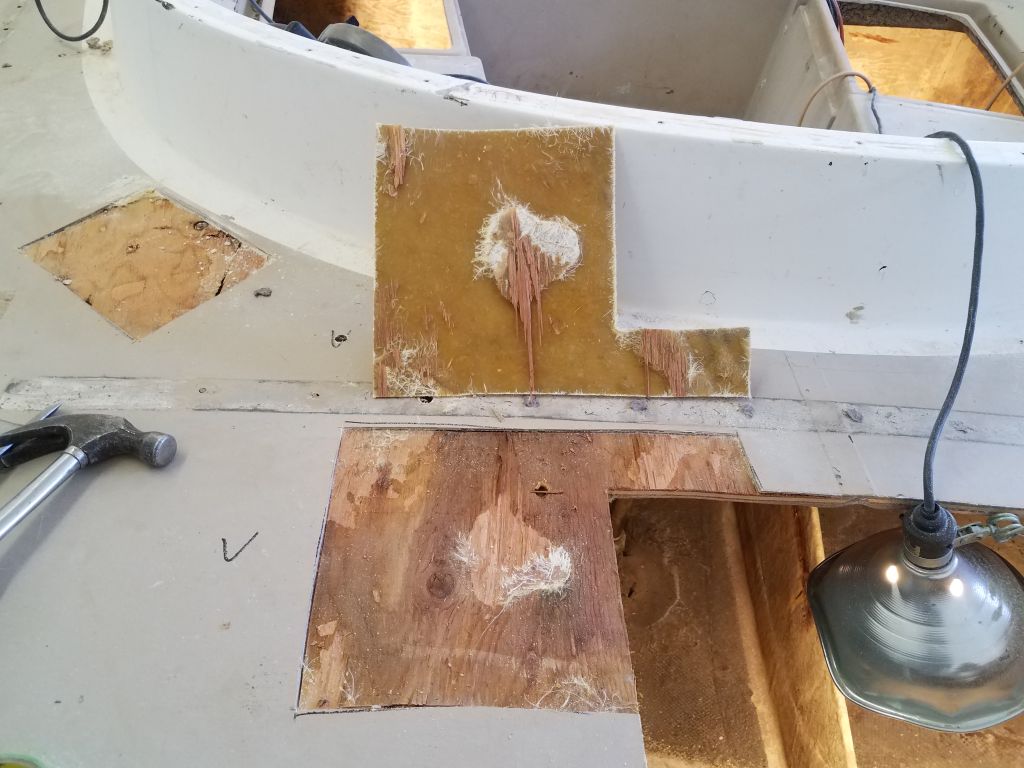
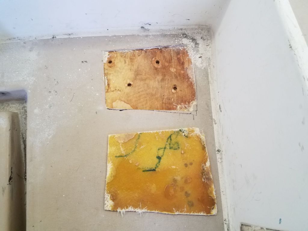
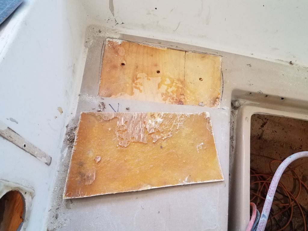
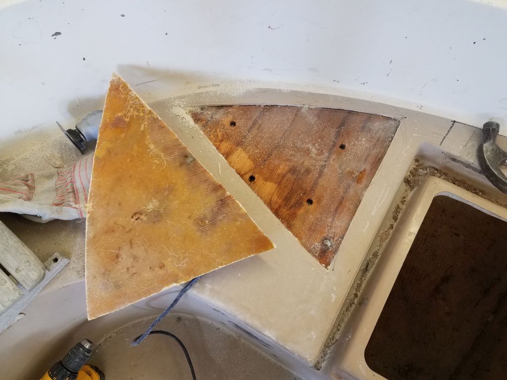
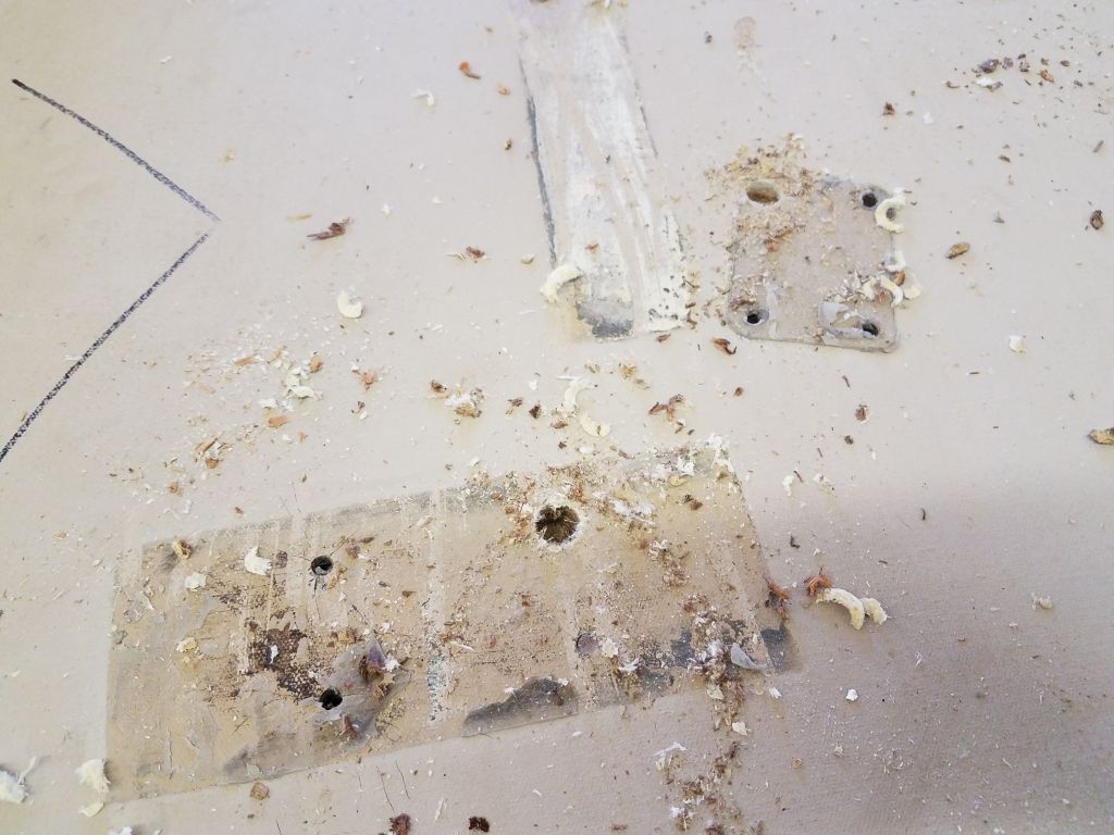
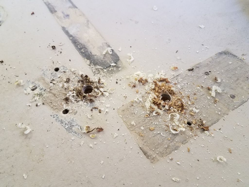
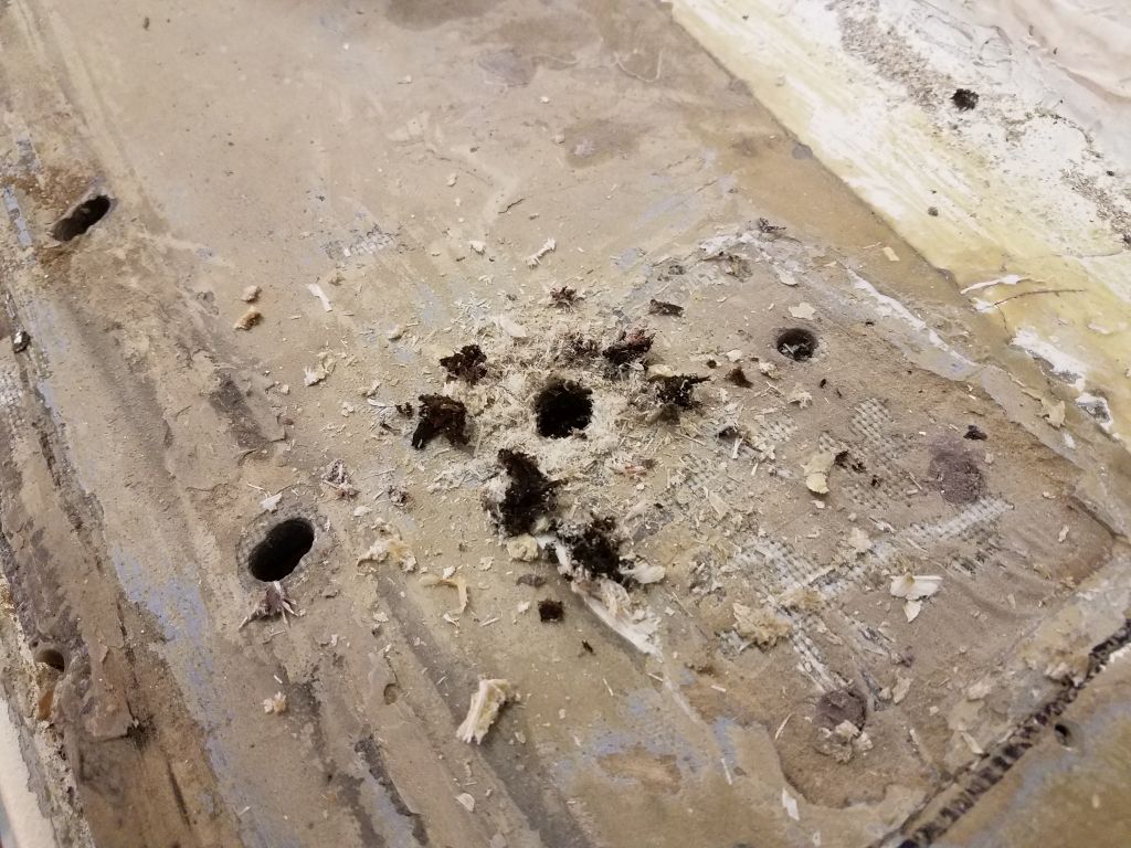
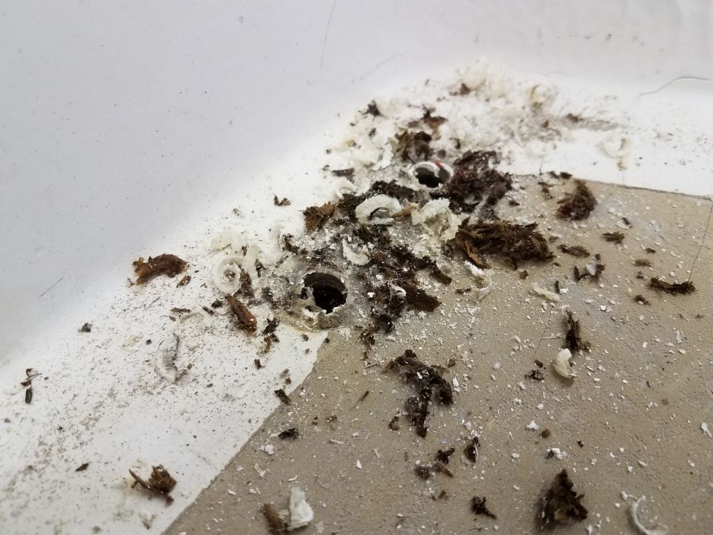
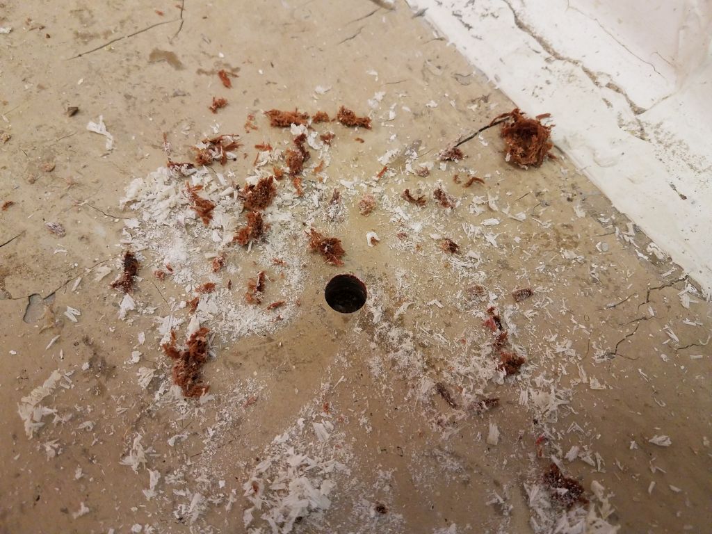
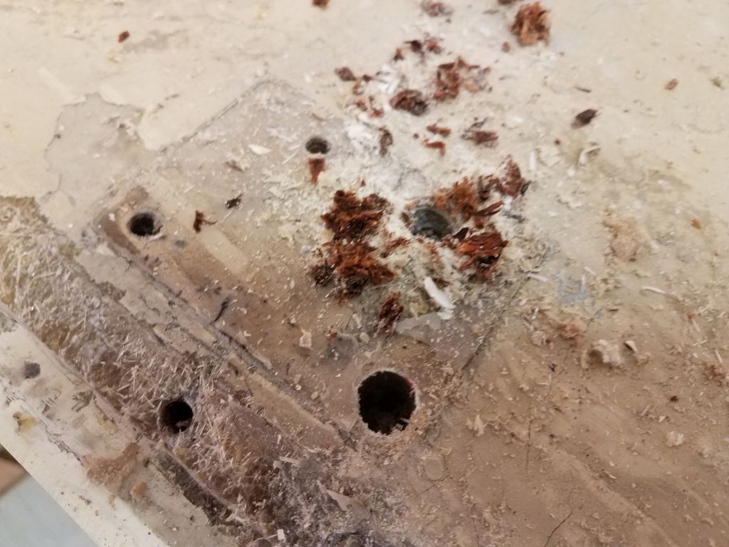
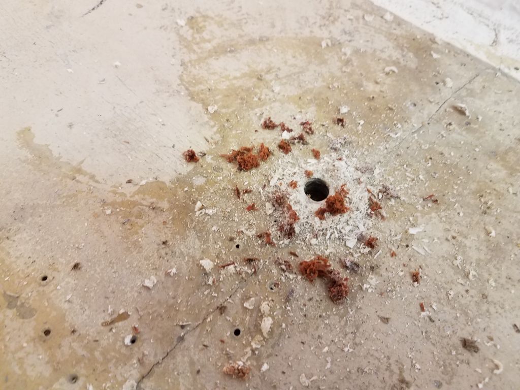
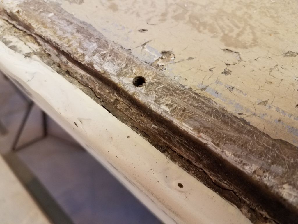
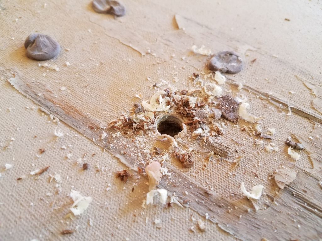
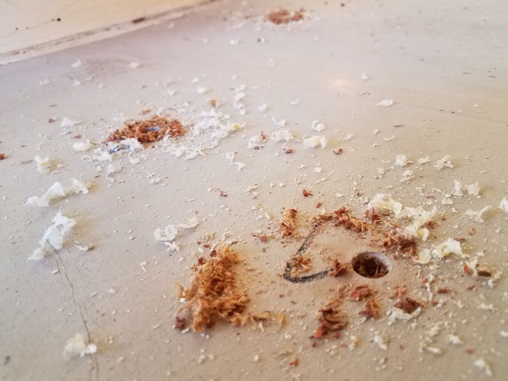
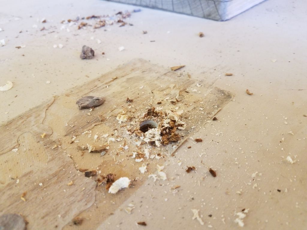
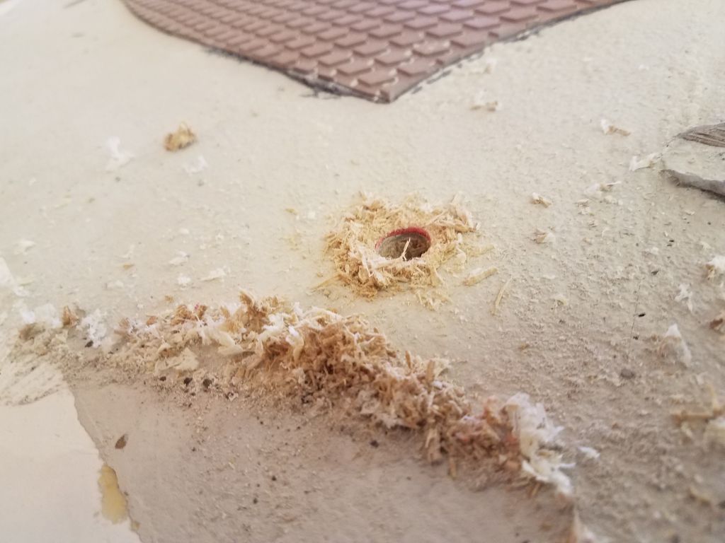
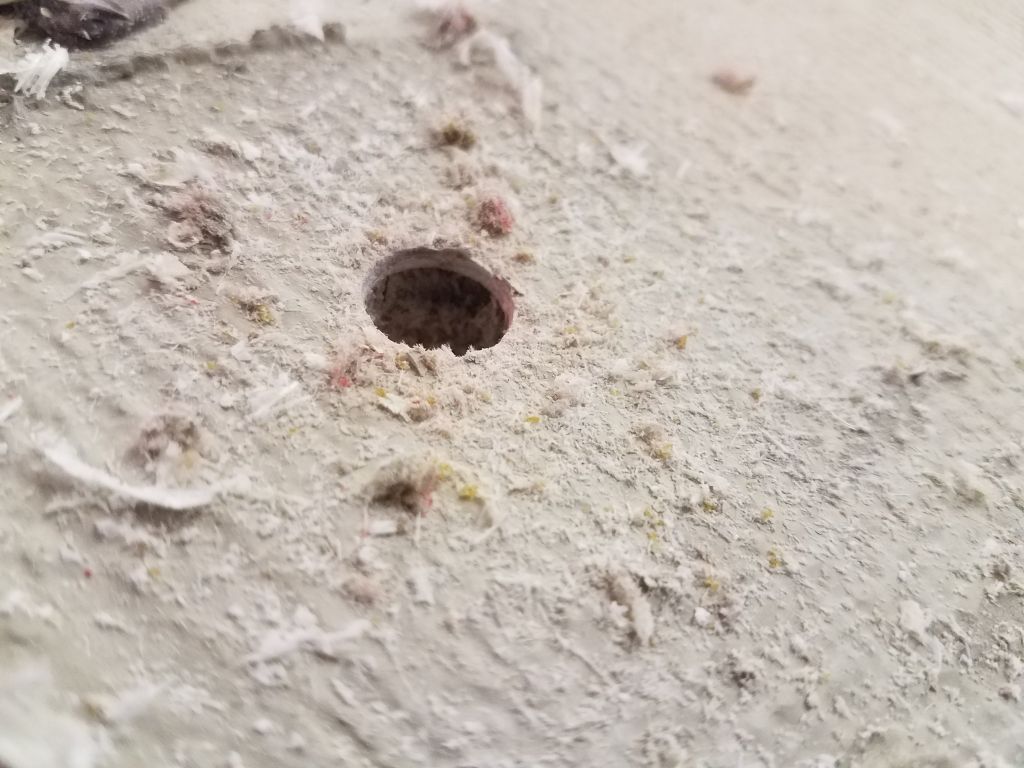
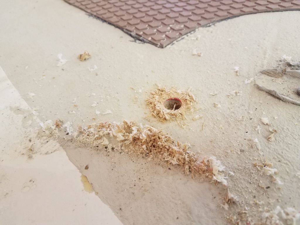
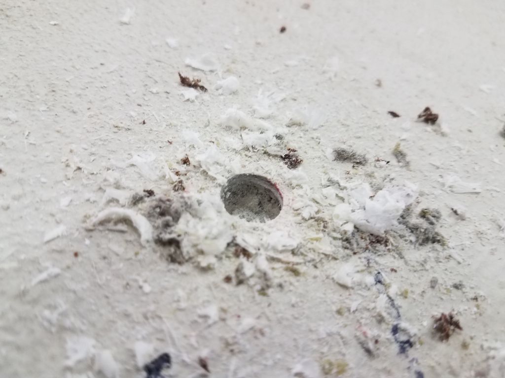
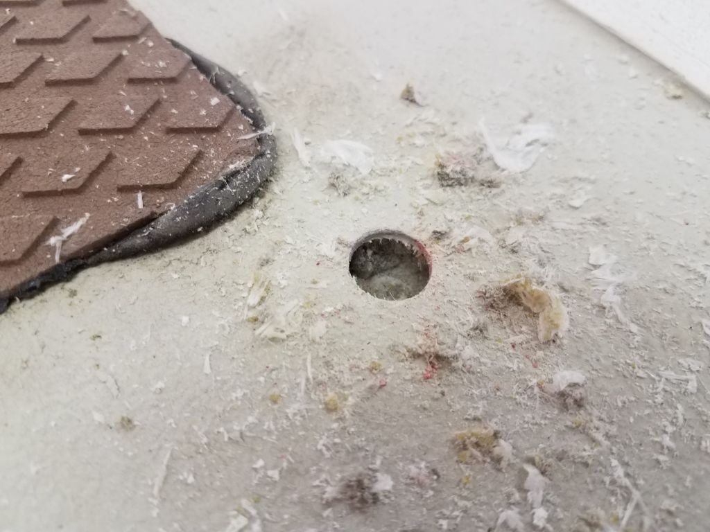
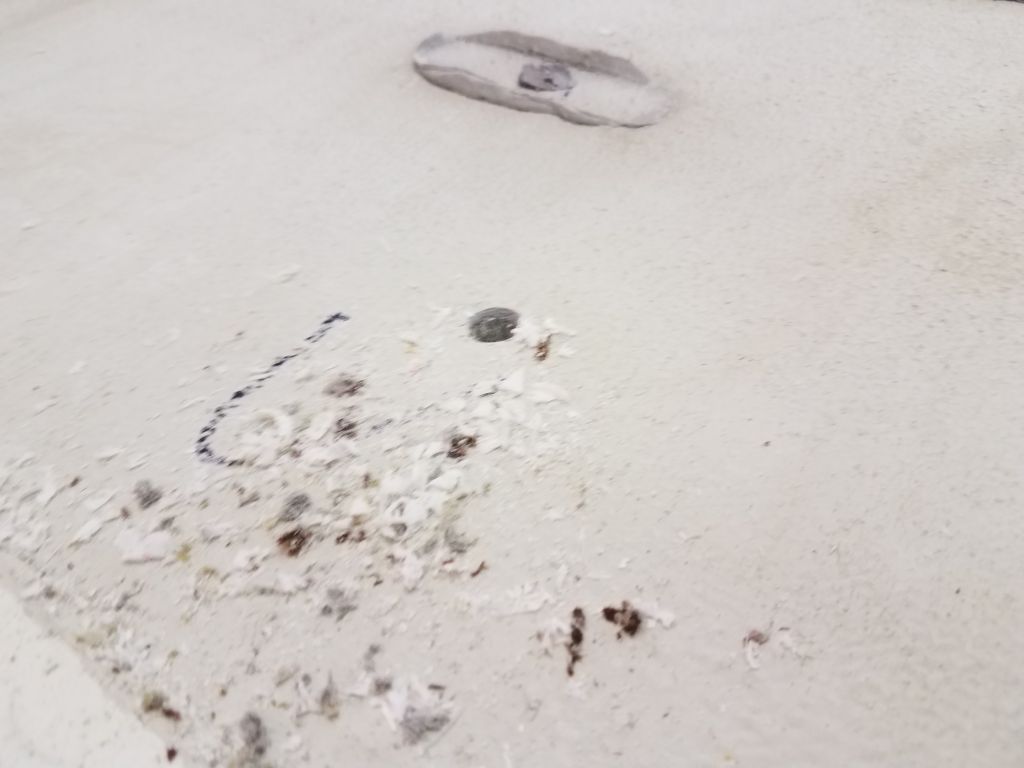
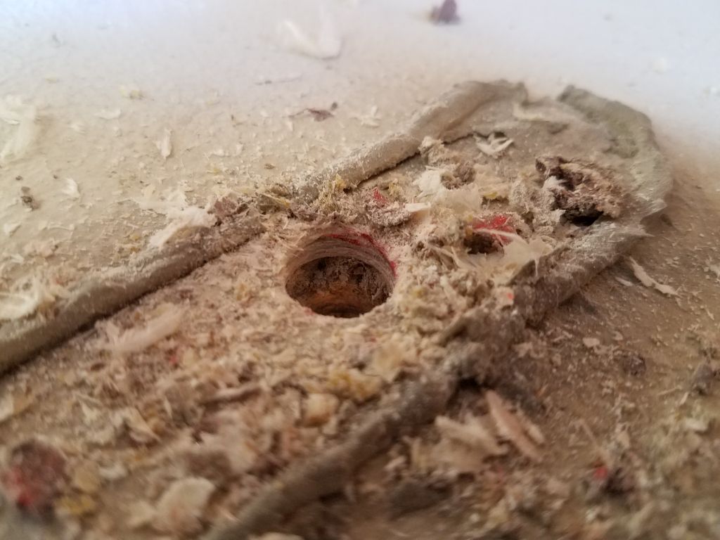
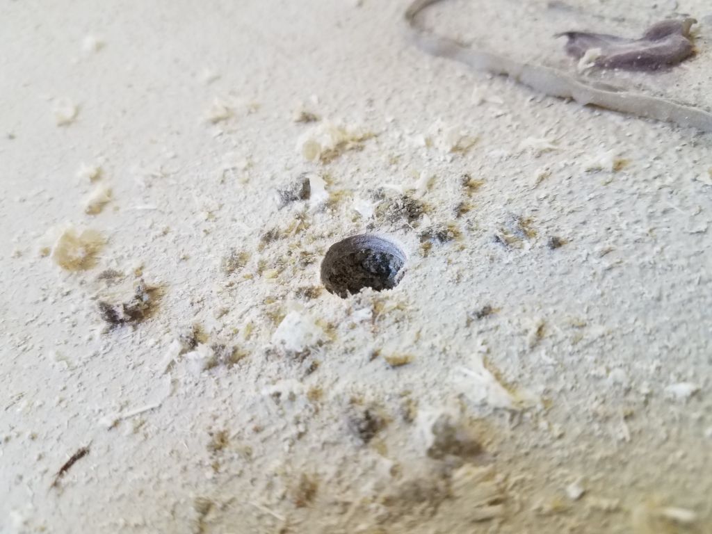
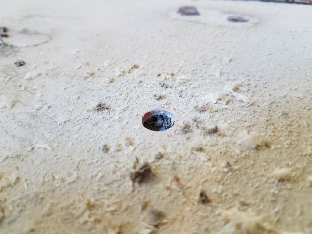
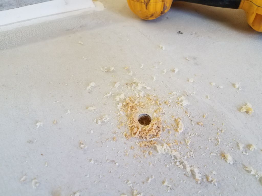
During the deck inspection, I’d found any number of small areas on the foredeck, starboard deck, cockpit seats and well, and poop deck (all original construction) where there was a clear separation between the top skin and core beneath (debonding). Core sampling in most of the areas revealed clean, dry core (plywood). Now I went around and removed the skins from these areas so I could install new fiberglass that might have a chance of bonding with the core, as the original had not.
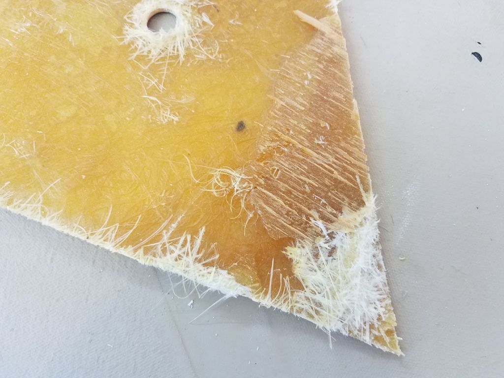
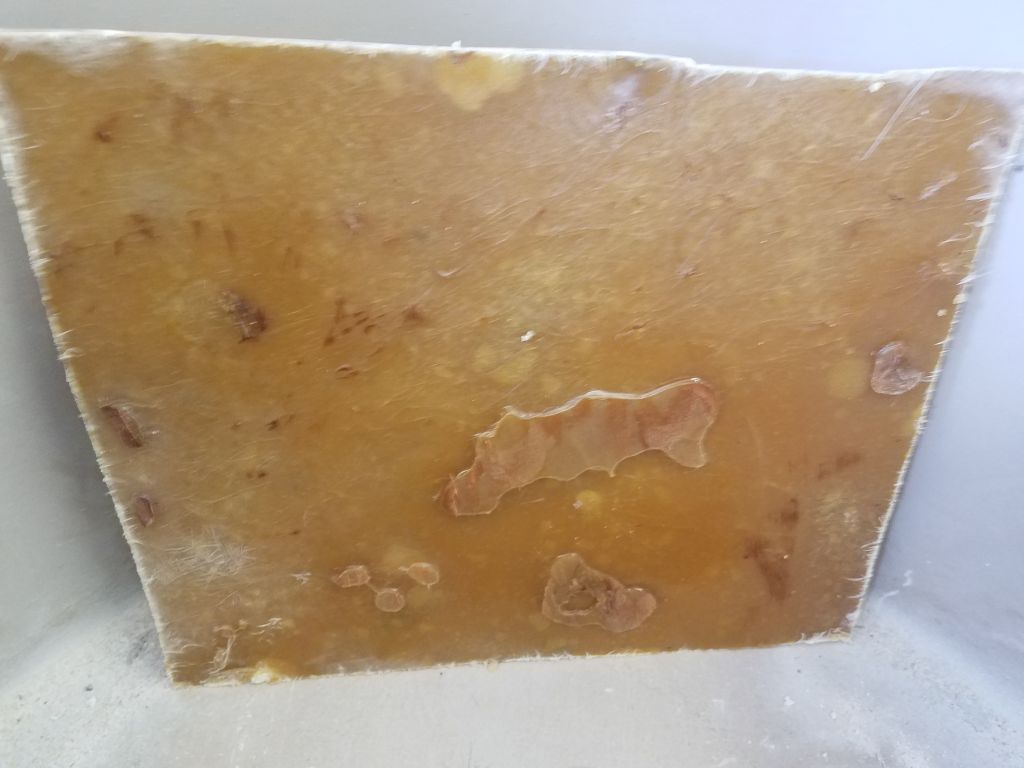
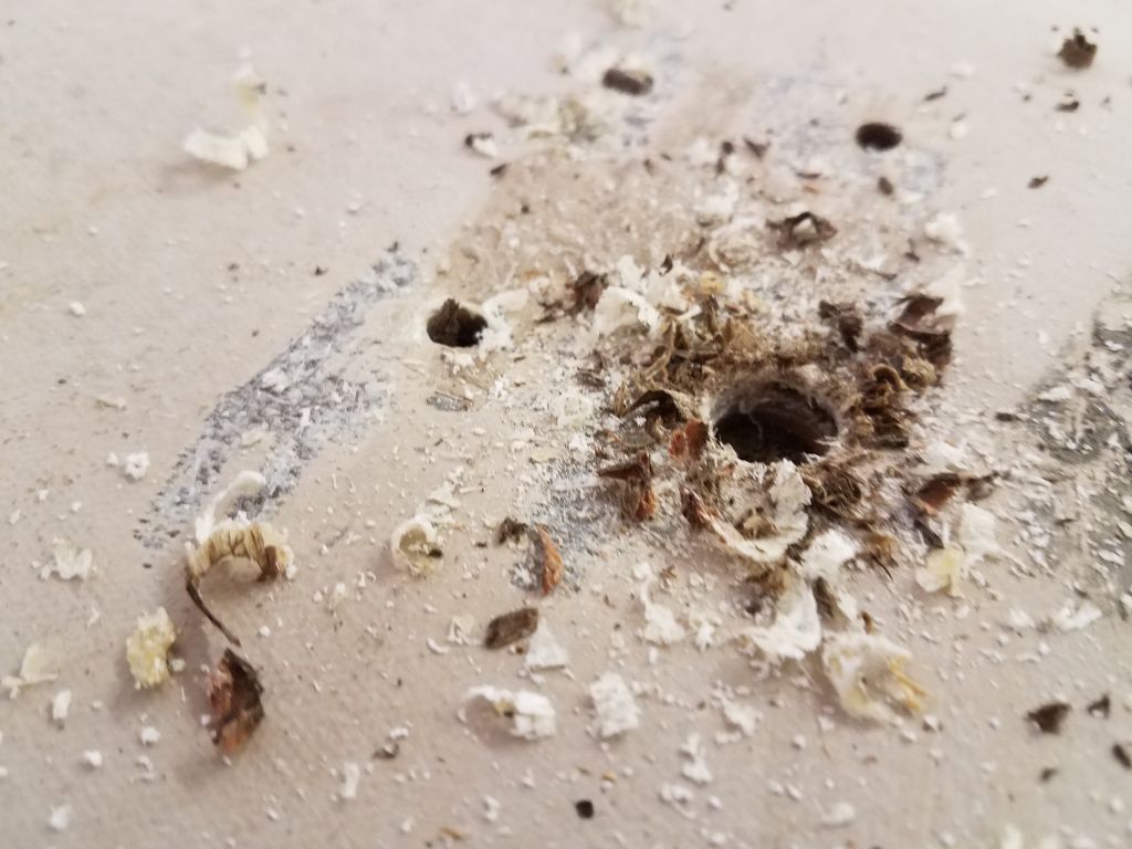
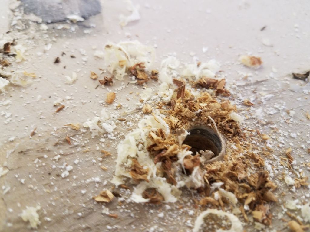
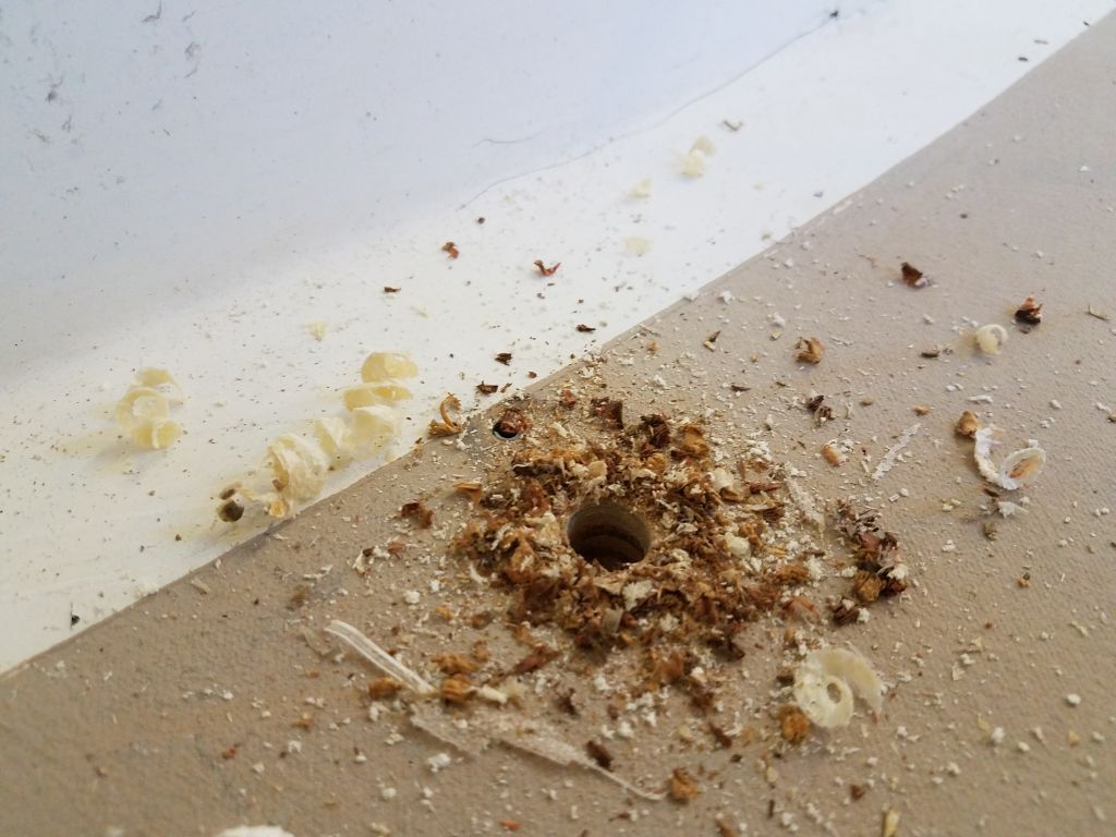
In most cases, when I removed the top skin (with virtually no effort),there was little or no sign of the core ever having been properly bonded to the skin, though in some areas I found small globs of whatever adhesive (resin-based) was used during the original construction to secure the plywood to the underside of the top skin, with virtually no contact between the core and the skin in other areas, so these voids were latent and had been there since the boat was first constructed.
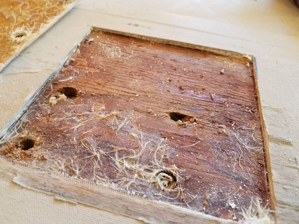
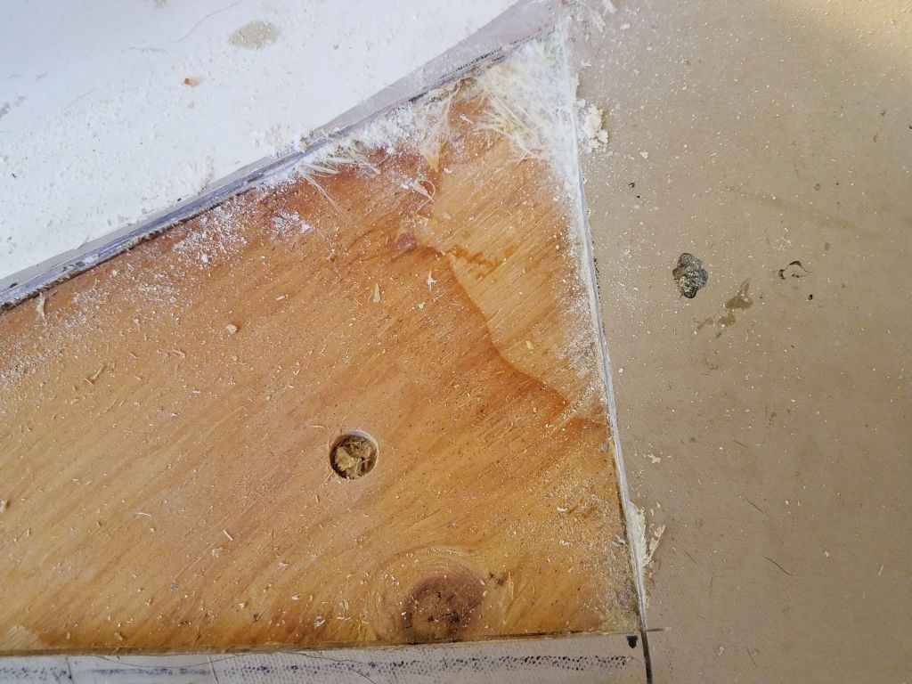
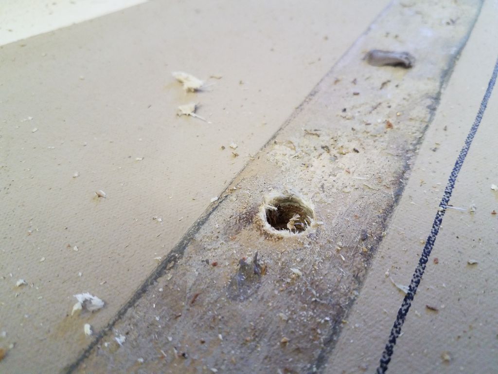
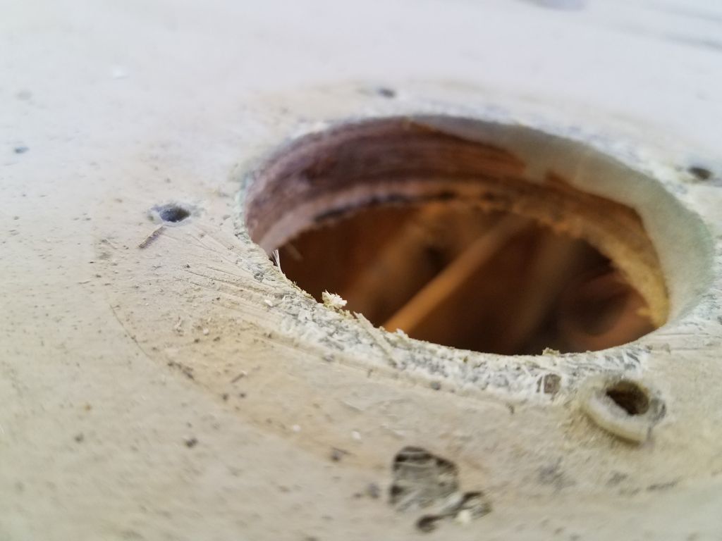
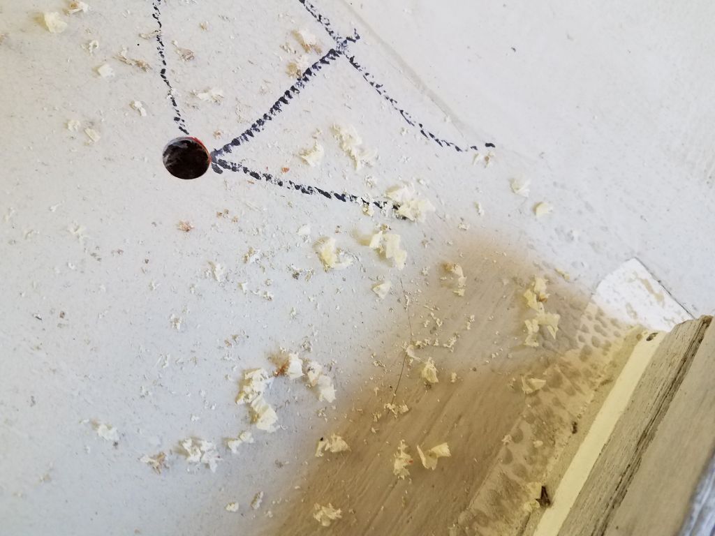
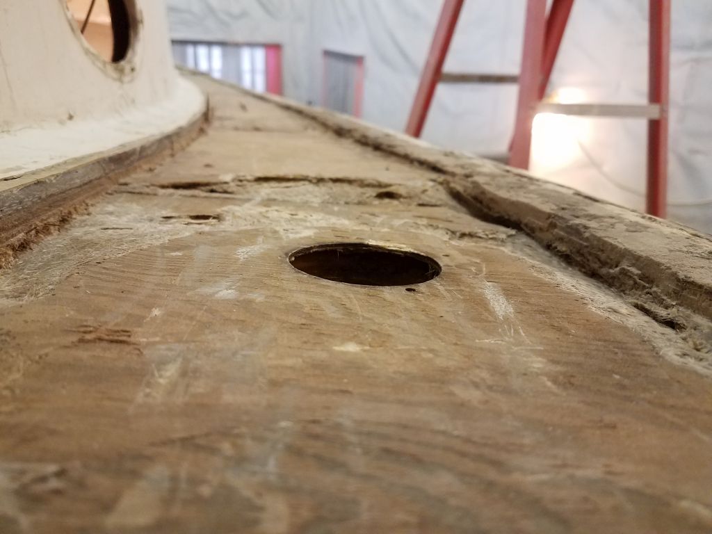
In many areas, I found clean holes apparently drilled into the plywood coring, though for what purpose I couldn’t imagine. These were separate from the various test holes (and in some cases old fastener holes) that penetrated the core. The coring was sound in all areas, and was simply a normal grade of plywood. I’d rebuild all these areas with new epoxy top skins in due course.
Next, I turned to the wide bridgedeck, where I knew most of the core was in poor condition. At first, thinking the center section of the deck might be sound, I limited my cuts to the end sections, but eventually decided to remove the entire center section too, since the damage extended far enough in some areas that it just made sense.
I spent the rest of the day cleaning out the old core from this large section, including around the edges, and cleaning up the spoils from the day’s removals.
Total time billed on this job today: 7 hours
0600 Weather Observation: 23°, clear. Forecast for the day: Sunny, 40°
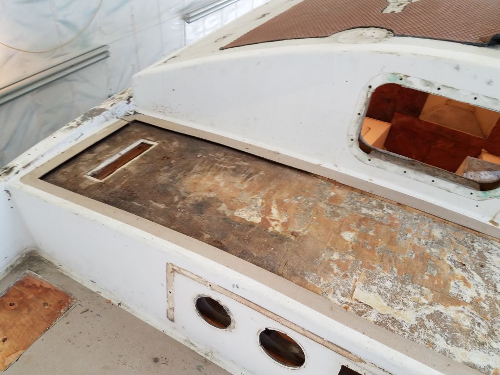
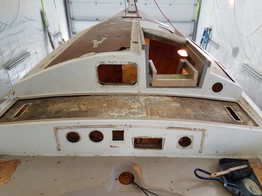
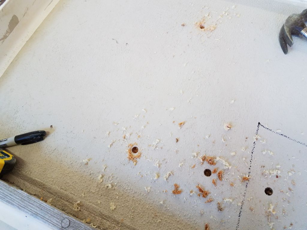
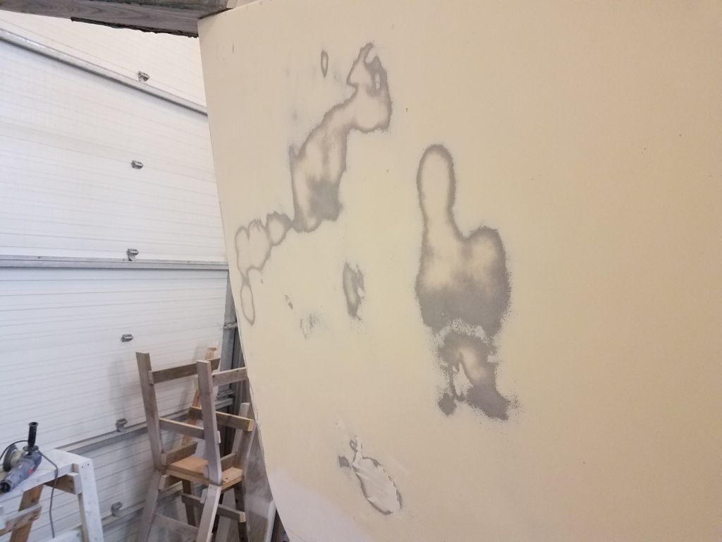
Armed with a hammer and drill, I went over all the deck areas to determine the overall condition of the structure and locate any areas requiring further inspection or repair work. I used the hammer to sound the decks, looking for indications of top-skin delamination or debonding, or wet and damaged core within.
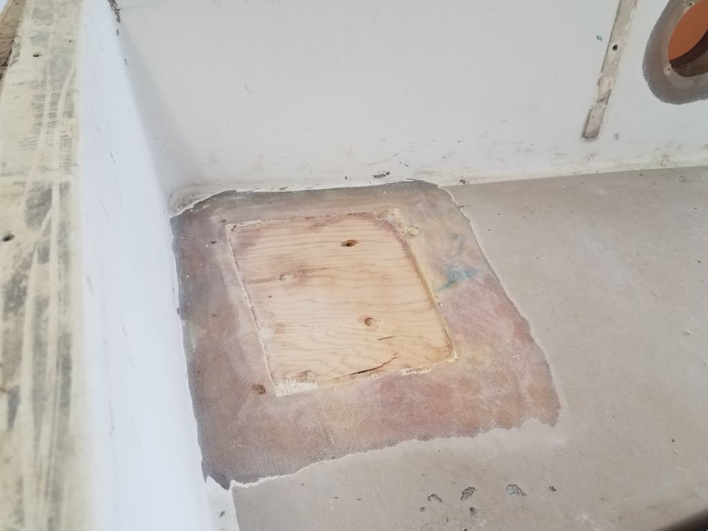
The poop deck, leading up to the winch pads on each side, was generally sound on both sides, with some minor top-skin delamination noted around the new opening for the deck hatch and in other isolated areas. The core was 3/8″ plywood, and my test holes here and there showed no signs of core damage, other than normal and expected discoloration around some of the old fastener holes. As in other original parts of the deck structure, the edge of the deck was solid fiberglass for quite a few inches in board before the core began.
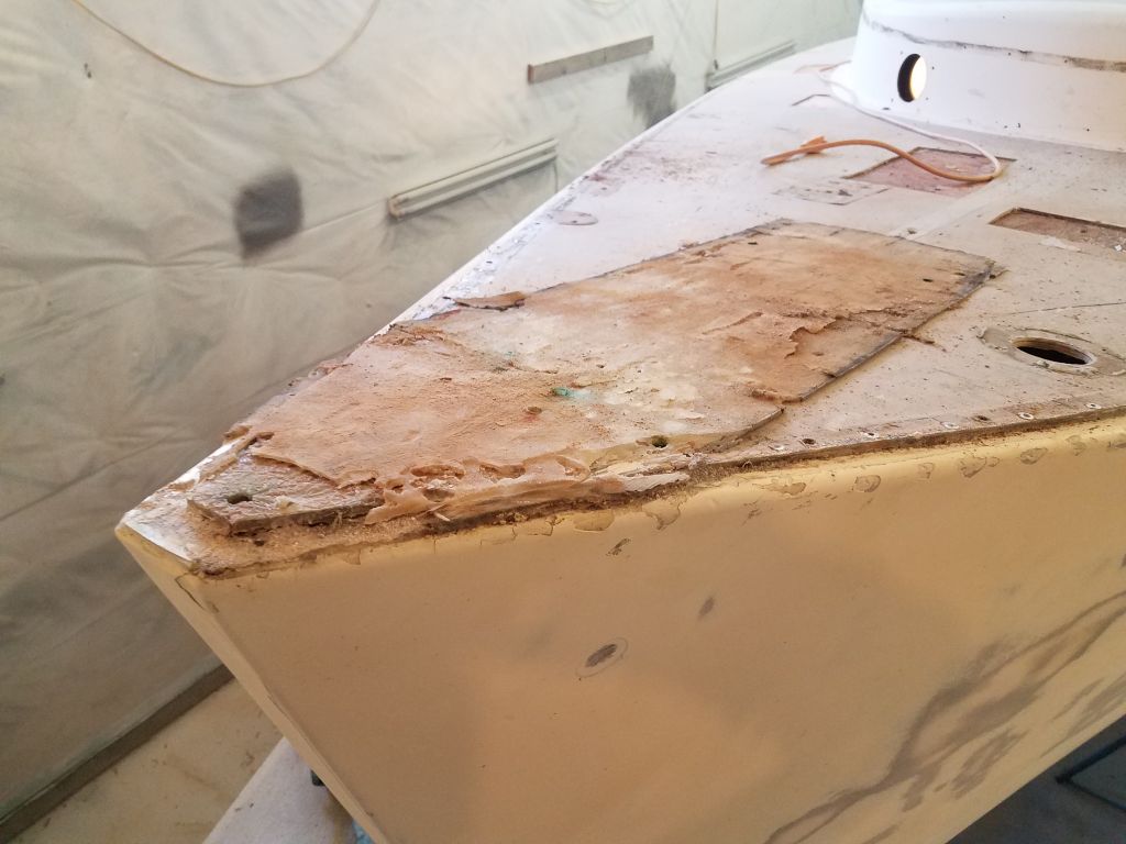
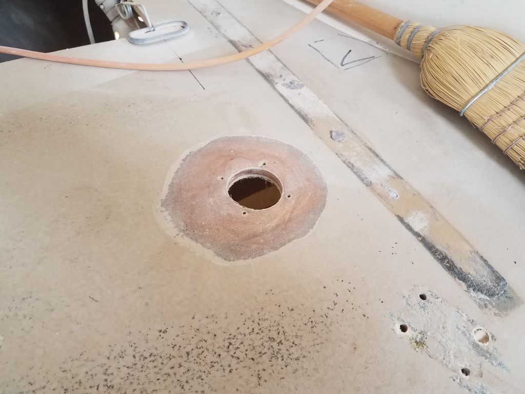
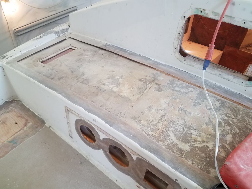
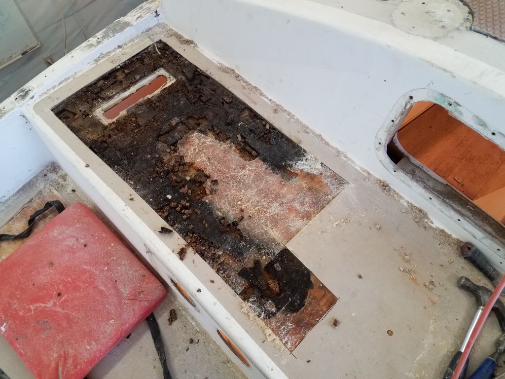
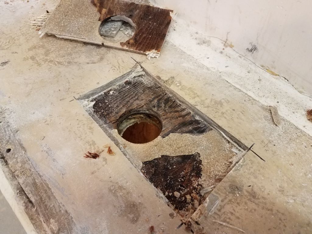
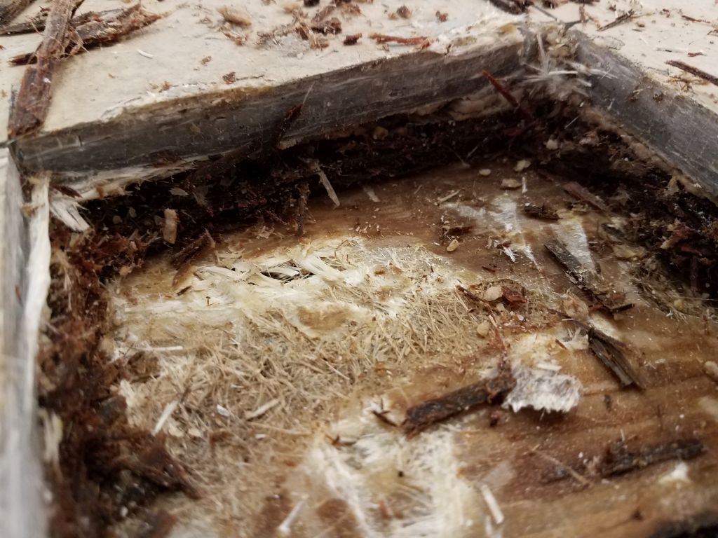
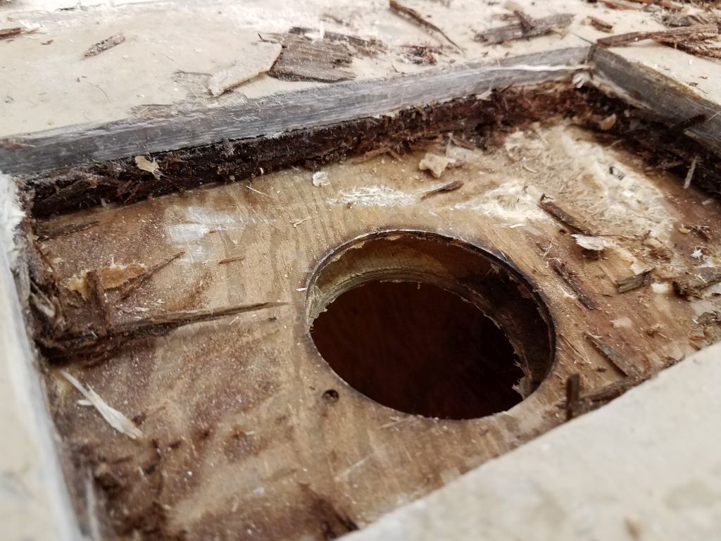
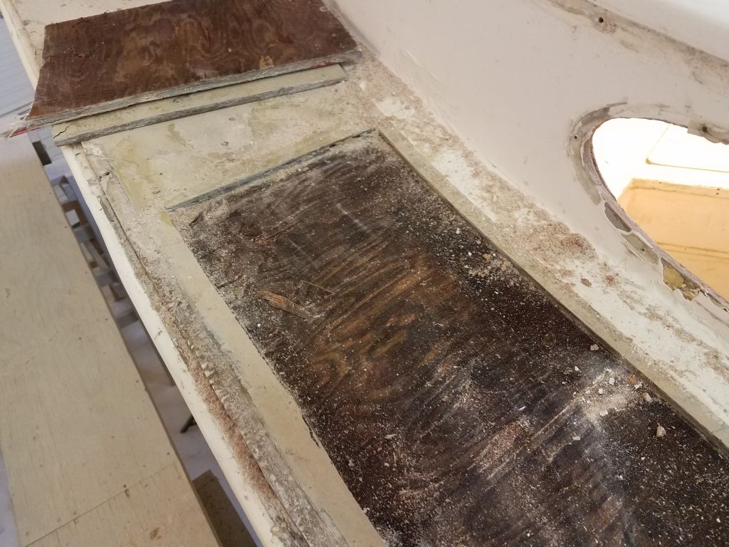
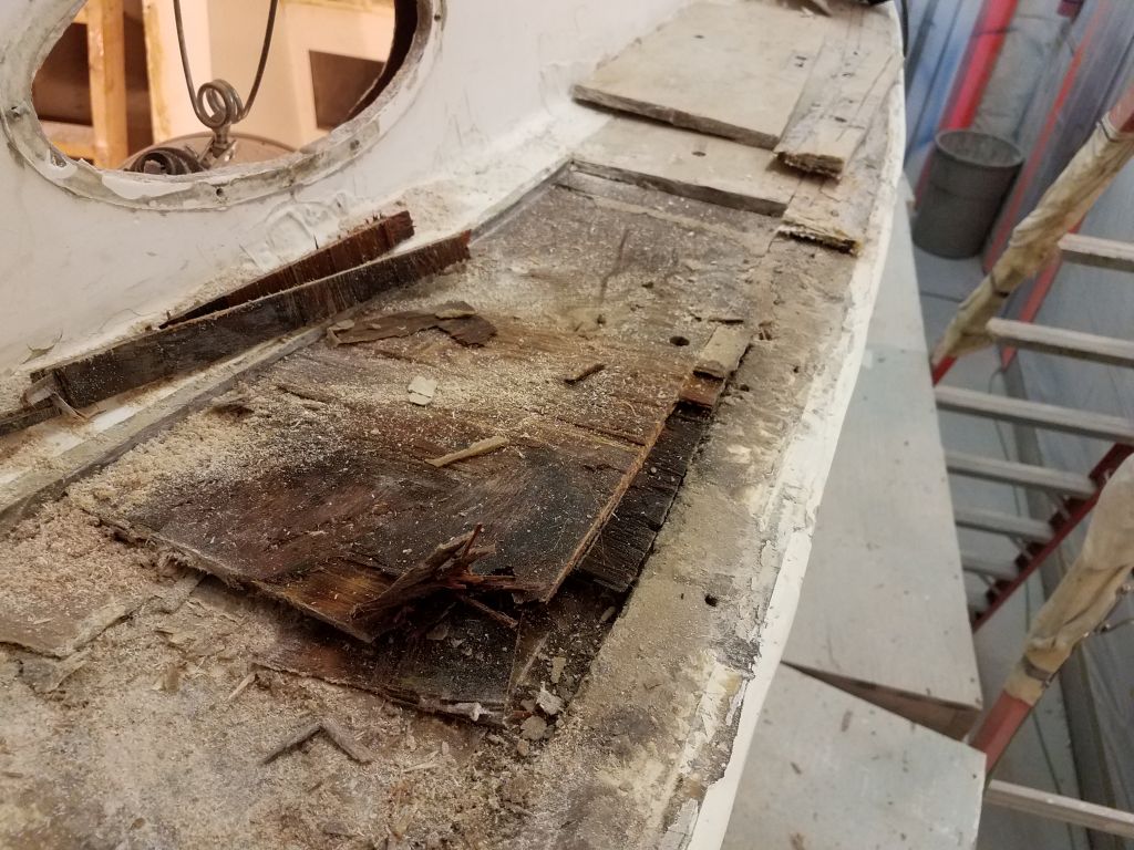
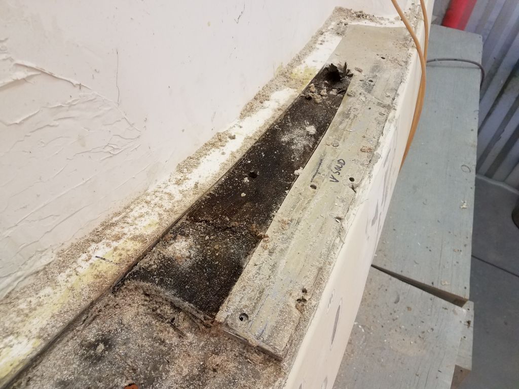
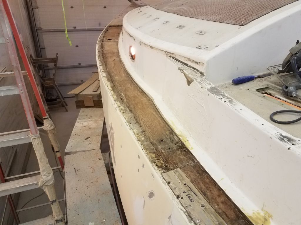
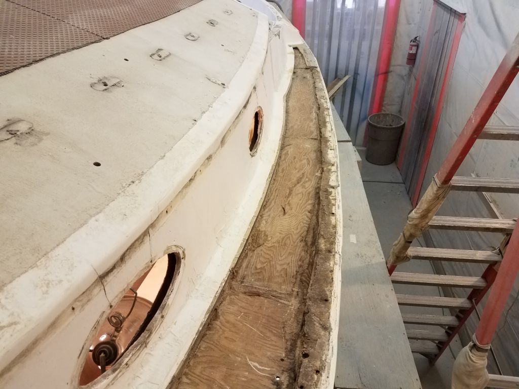
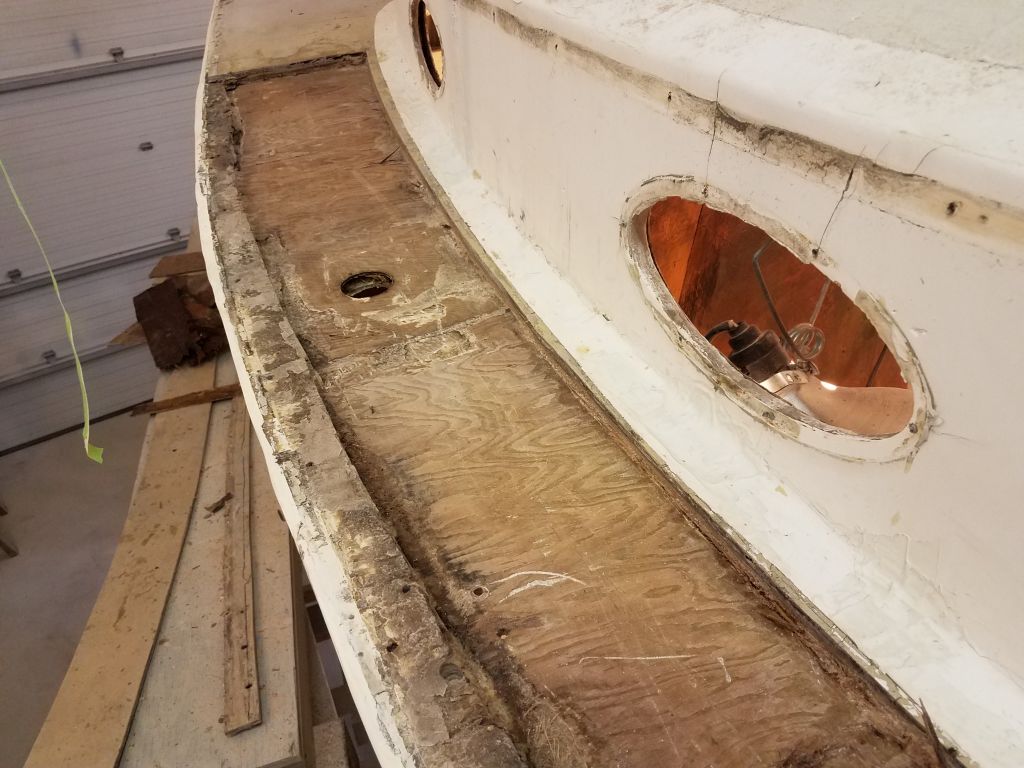
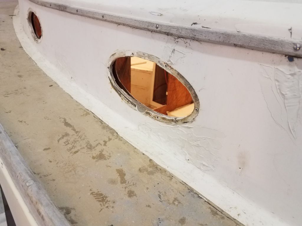
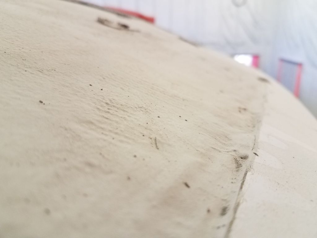
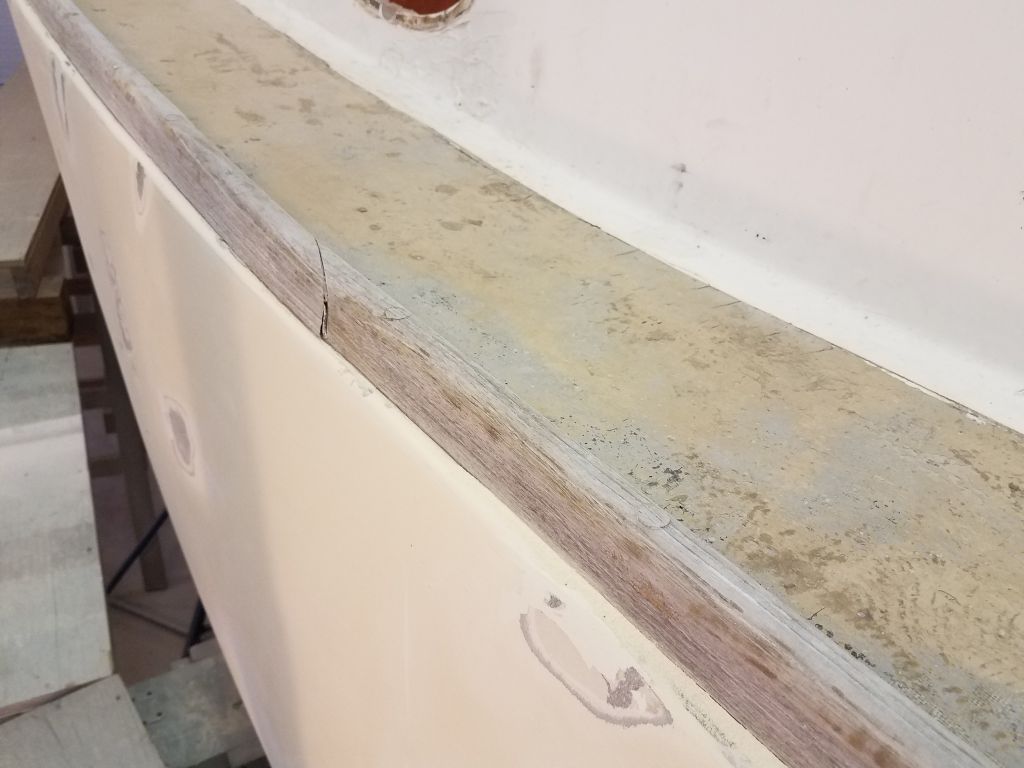
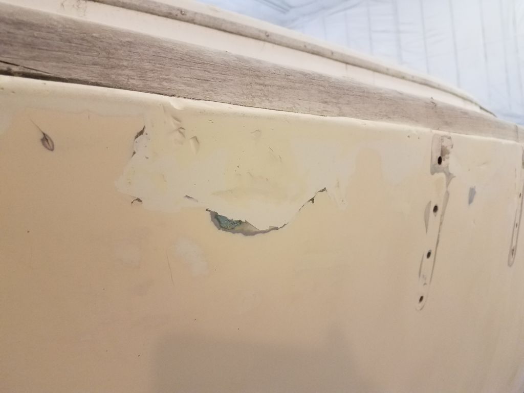
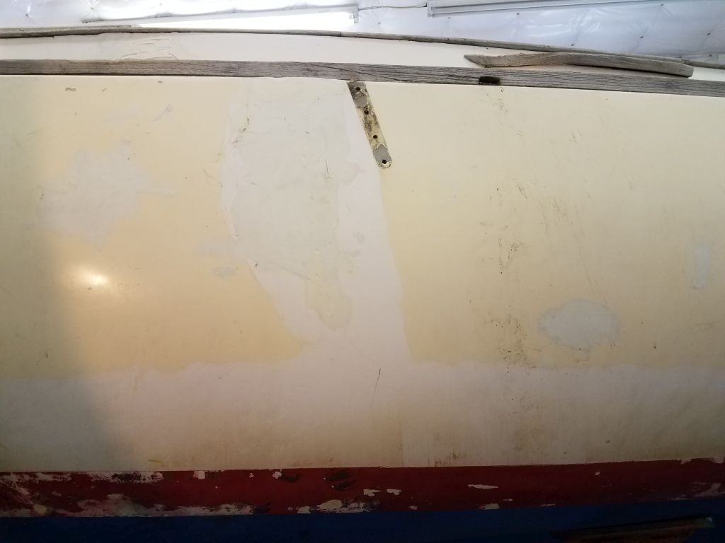
The condition of the port sidedeck had bee a concern since the moment I first saw it upon the boat’s arrival here, but there were many questions about it and even after various related work I still was unsure what was going on. Sounding tests were OK, but this wasn’t a big surprise since the top skin–which was part of a previous repair and not original–was extremely thick and resin-rich, as indicated through the old water tank fill hole, which I’d opened up earlier in the job.
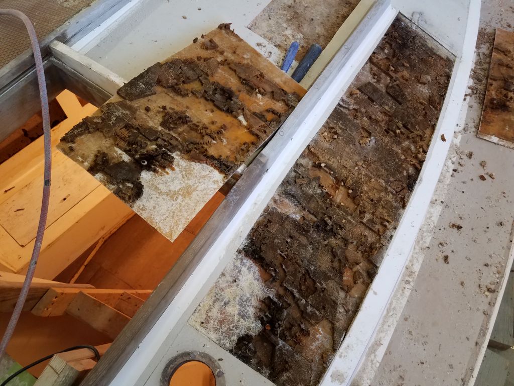
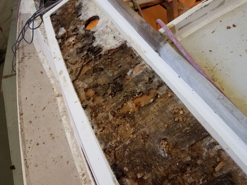
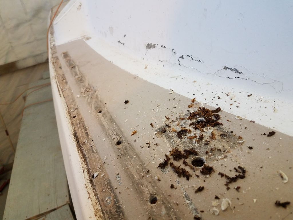
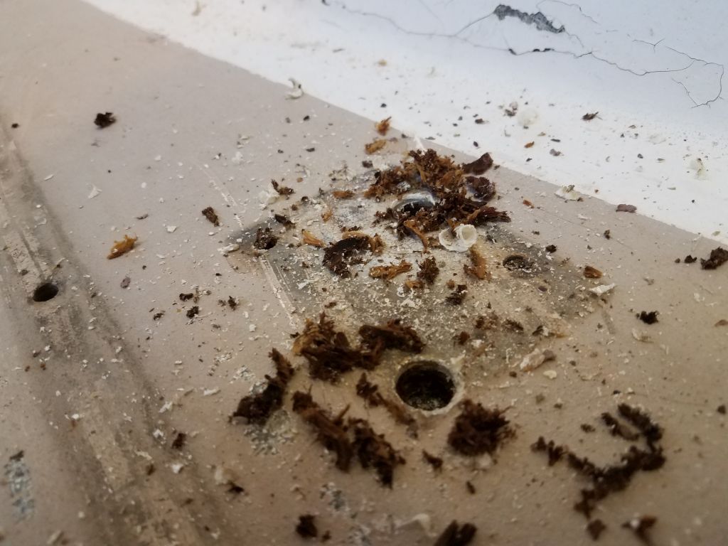
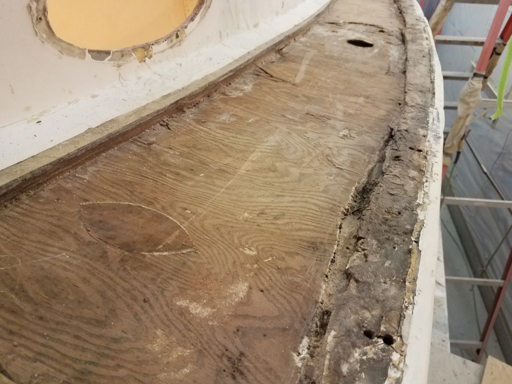
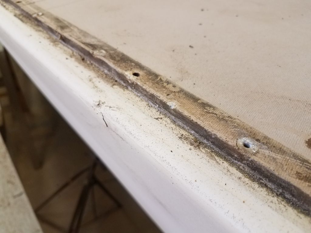
I drilled numerous test holes along the length of this deck, and in each case the core spoils–plywood again–came up dark and damp. This was not a surprise, as I’d noted the wet core as soon as I removed the deck fill earlier, but even so I’d been hoping that perhaps the whole area wasn’t wet, though in my heart I knew it would be.
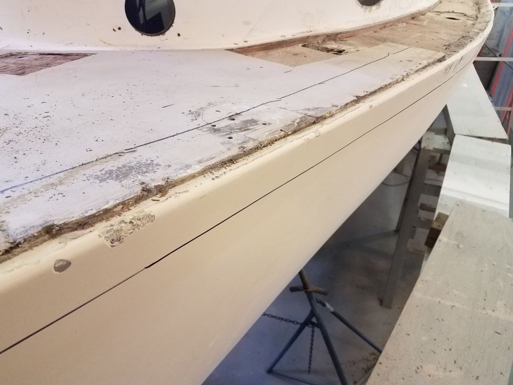
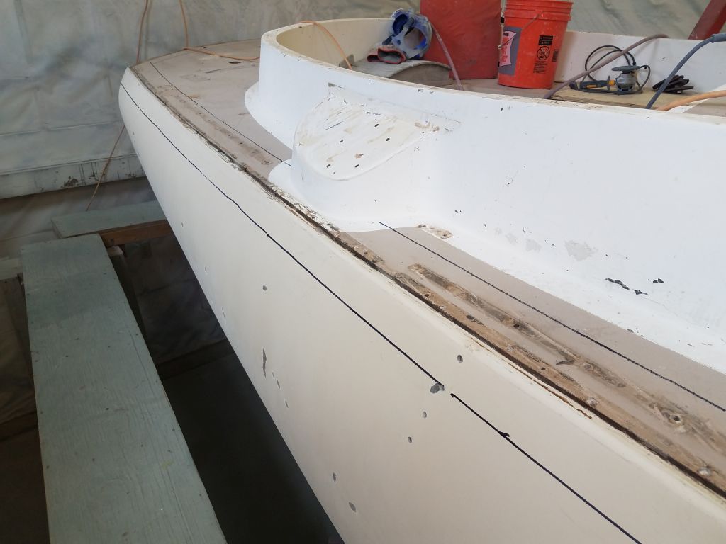
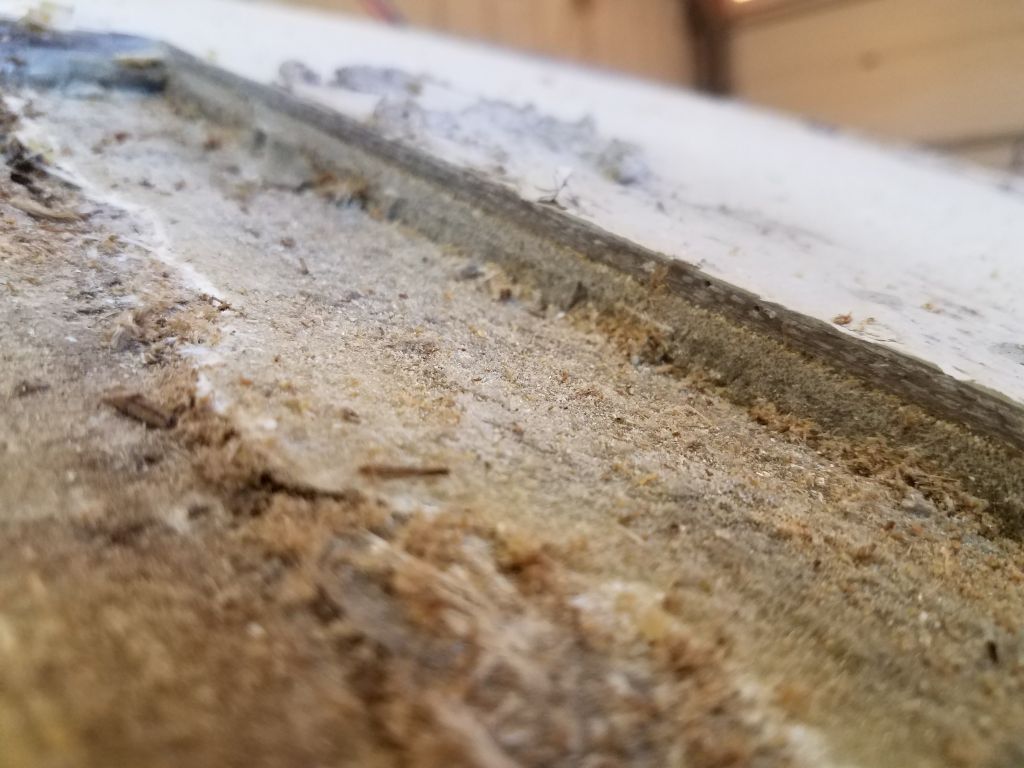
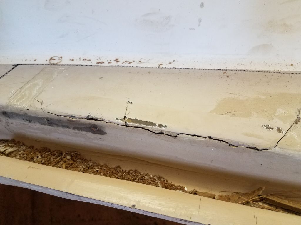
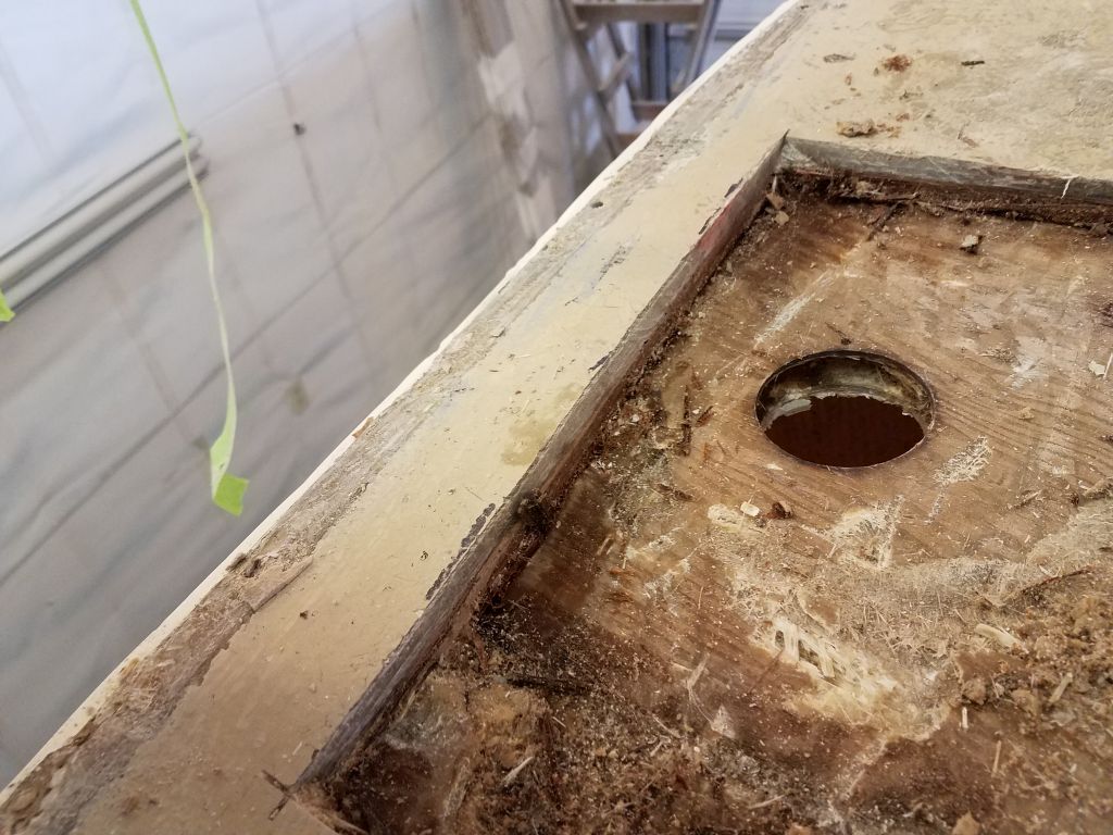
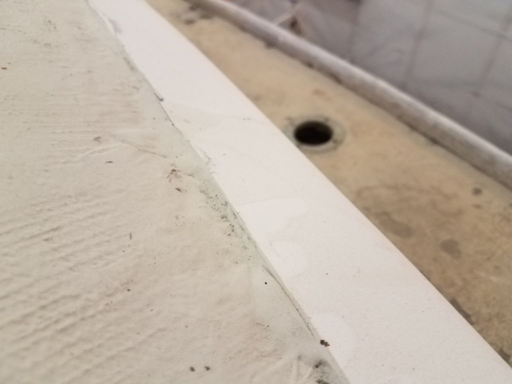
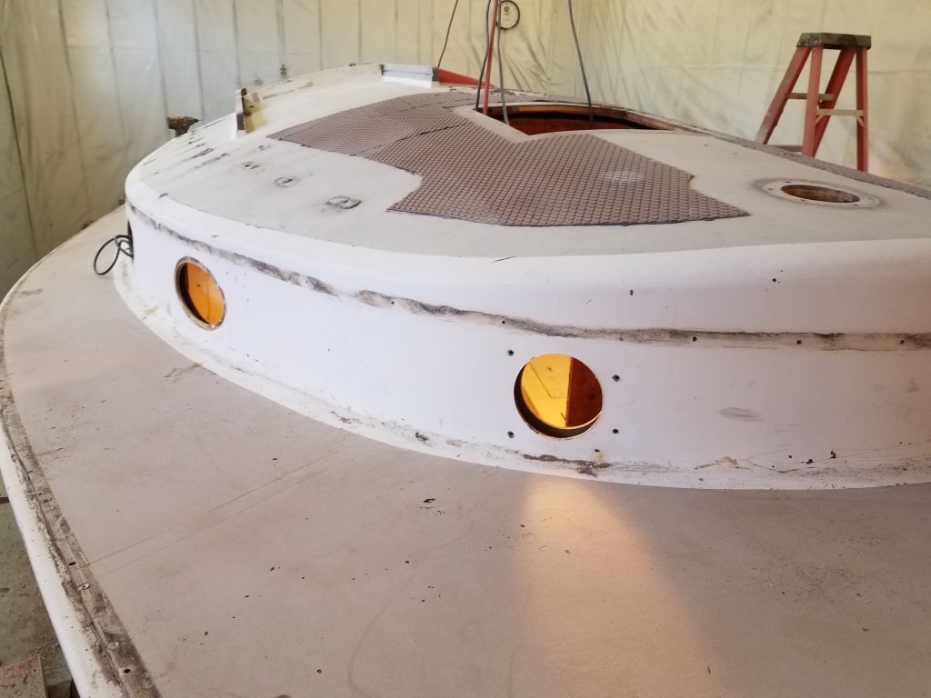
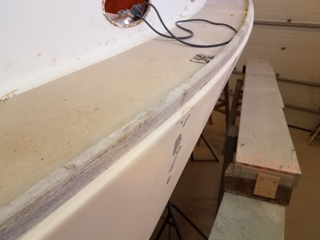
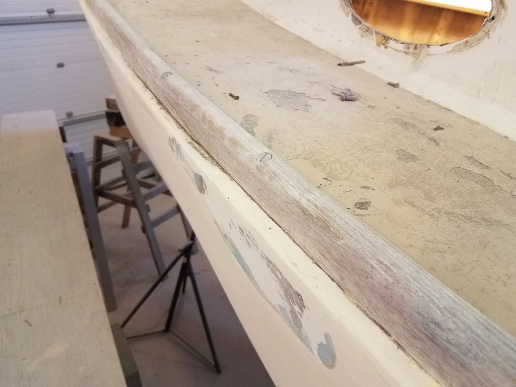
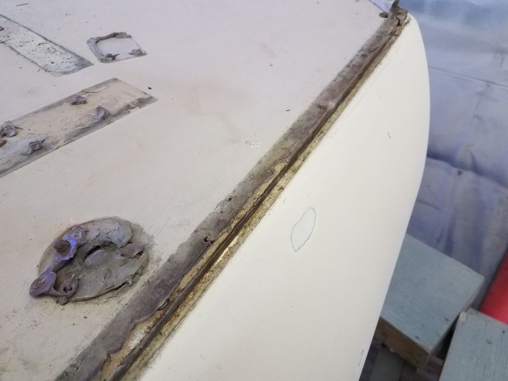
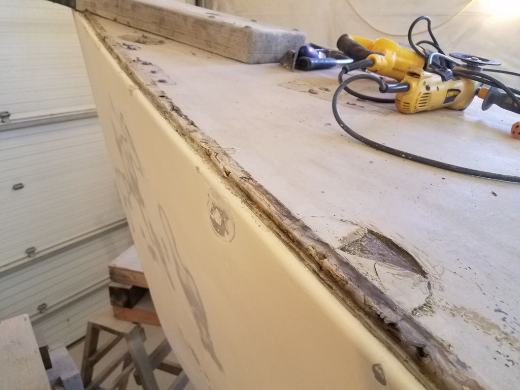
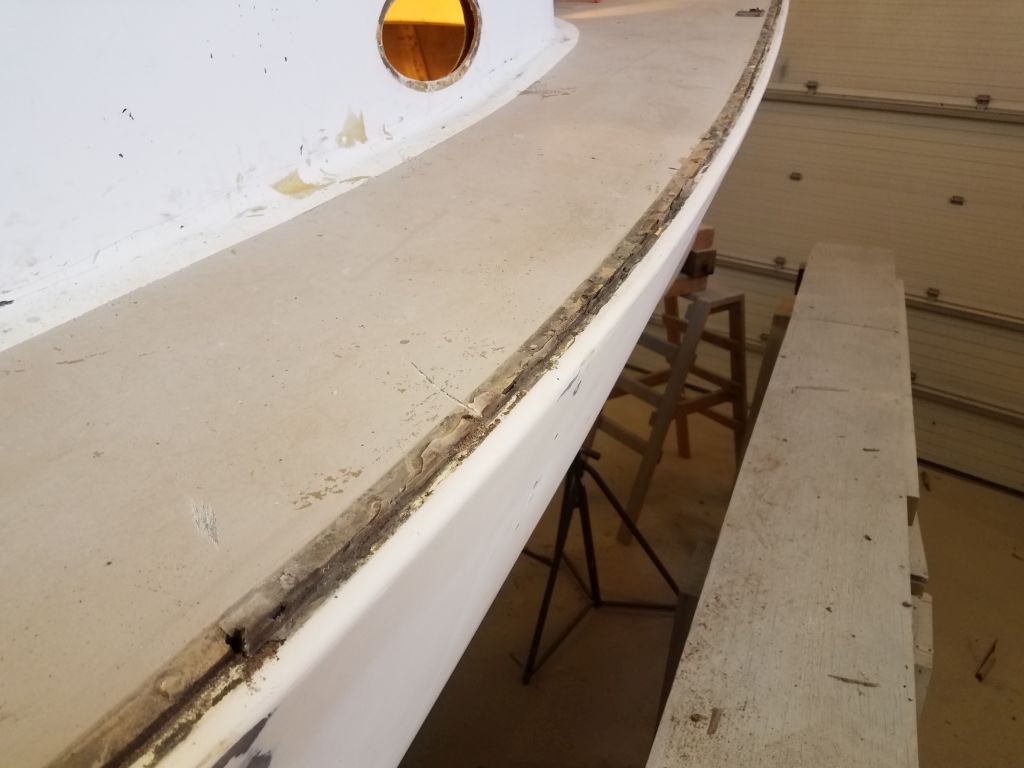
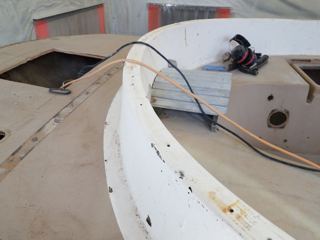
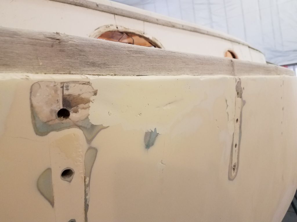
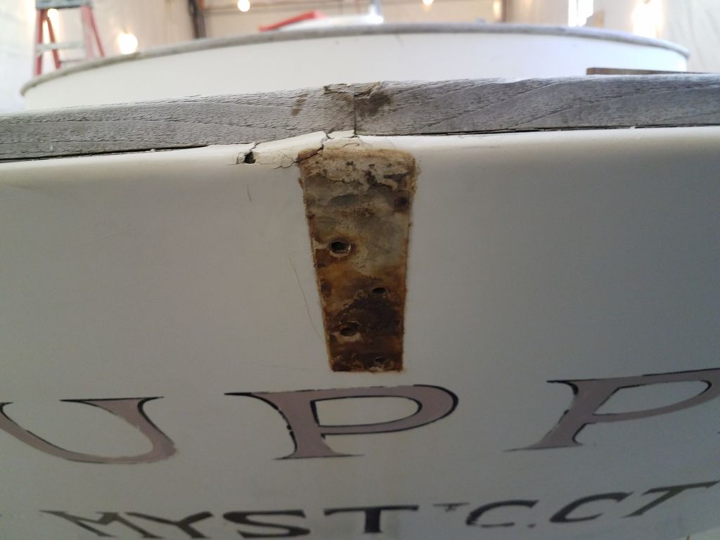
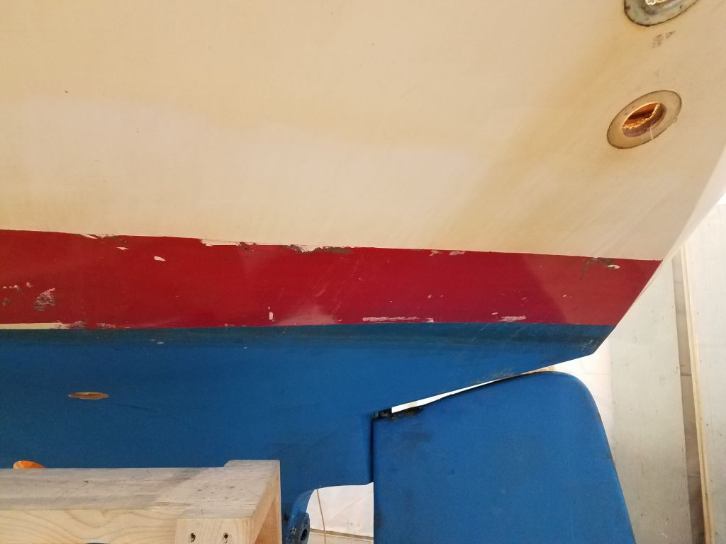
This area along the edge of the deck, where it joined the hull, caught my eye, though at the time I wasn’t sure what caused the visible cracking at the edge of the deck. I’d soon find out.
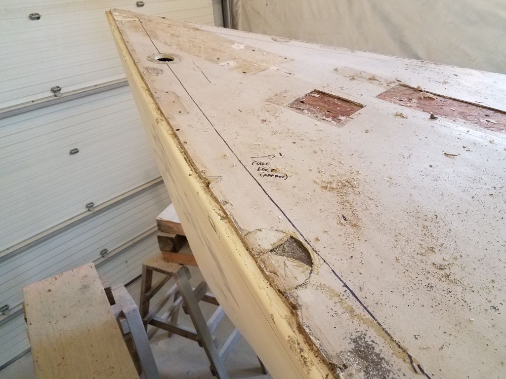
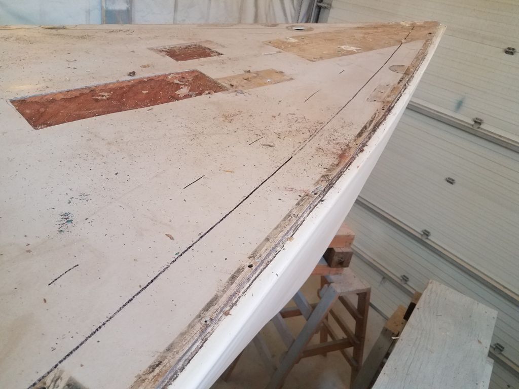
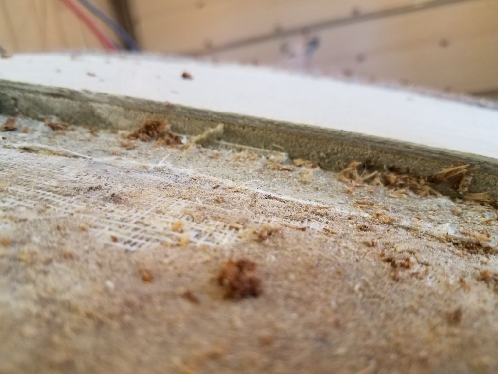
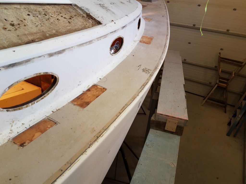
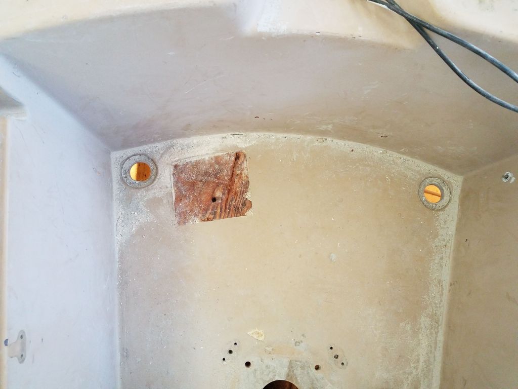
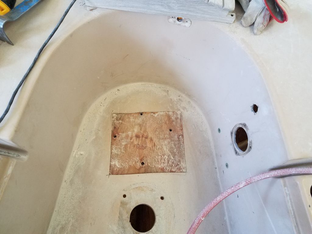
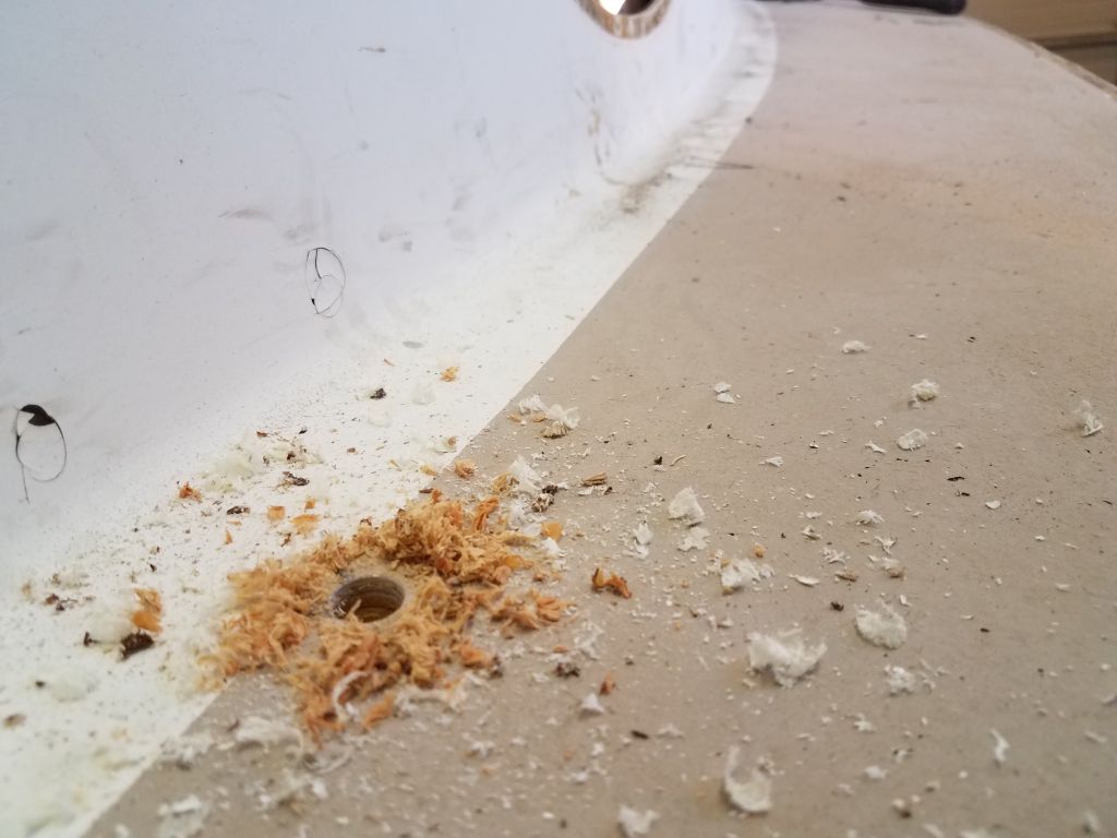
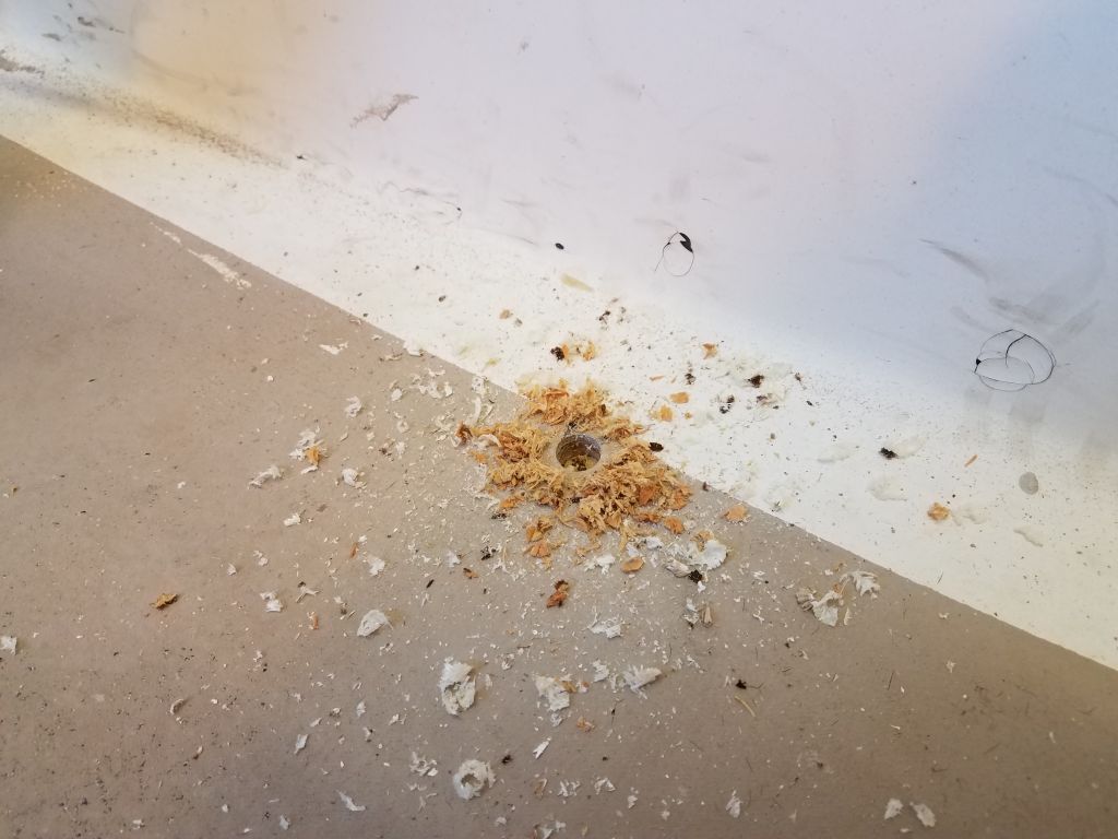
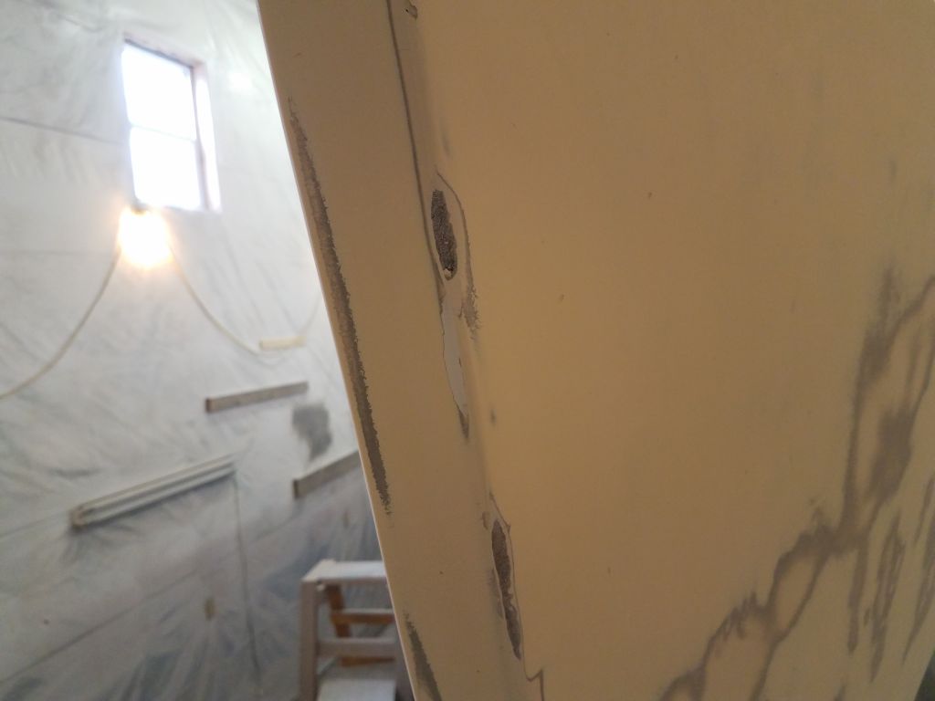
Portions of the foredeck on the port side showed signs of moisture in the (still plywood) core, though this part of the deck was original construction. Here, the solid part of the deck was nearly 7″ inboard from the edge, at least as an educated guess from measuring inside the boat through a couple of the old hardware openings in the molded cabin liner. I wanted to know how far in the core edge was in all areas so that if it came to core removal, I’d know where to begin my cuts.
I found some dark and wet core in one of the first test holes on the starboard sidedeck, aft in way of a stanchion base location, but moving forward I found clean and dry plywood core, though as in most areas of the deck there was sporadic small areas where the top skin either had never bonded to the core, or had come free over time–such latent defects were always an issue in vintage polyester construction, and even more so with plywood coring, but overall were little cause for concern.
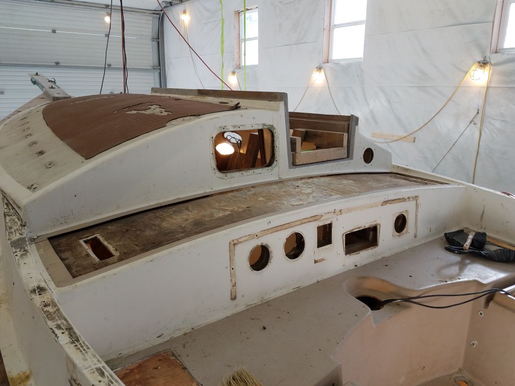
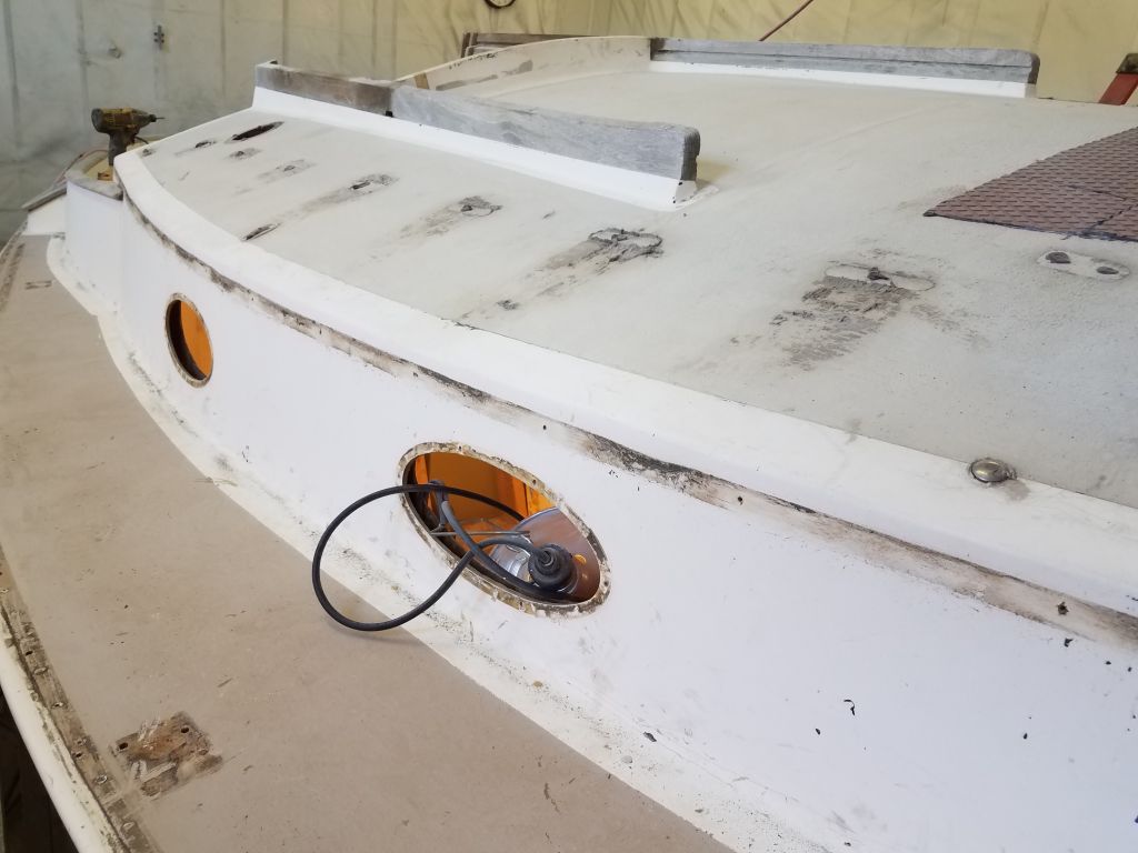
The entire port side of the coachroof and most of the forward section had obviously been repaired in the past, and roughly so. Where these areas weren’t covered with Treadmaster, it was clear the deck surface was rough and poorly faired, and was clearly work more recent than original. Sounding results were fair over the area, and in the forward part of the boat the deck was cored with balsa, visible through the hatch opening and old solar vent location. In the other areas, however, and in way of the obvious repairs, the deck turned out to be cored with some sort of foam, as indicated by numerous test holes that I drilled. Despite the poor outward appearance and rough construction, I didn’t immediately find significant cause for concern in the largest area of the coachroof, though for the moment I reserved final judgement pending additional work and investigation as needed.
The small section of the starboard coachroof outboard of the companionway appeared to be original, and here the deck was soft and in all ways indicative of damaged core, all confirmed with sounding and test holes.
This short video attempts to show the debonding of the top skin from the damaged core within.
The area inside the companionway rails, just aft of where the previous repairs had occurred, also showed signs of being partially wet and soft, though the condition of the core samples improved as I moved aft.
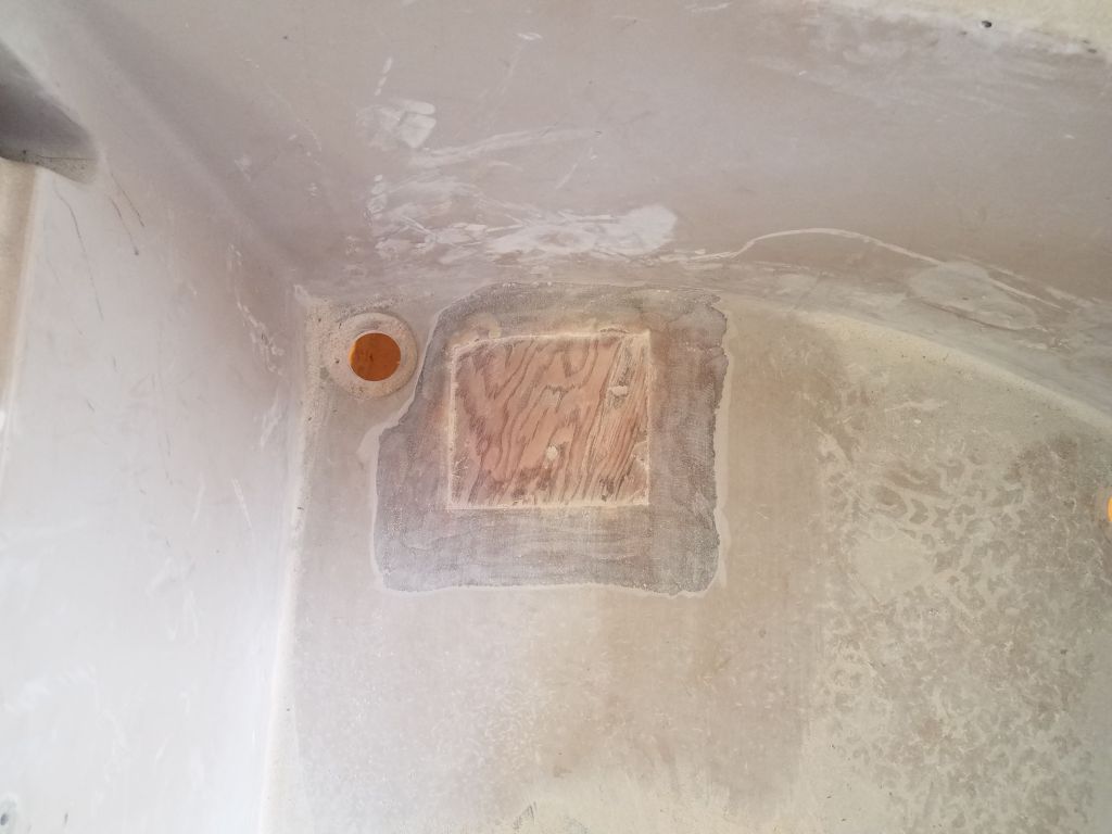
The cockpit areas, other than the bridgedeck, seemed generally sound overall, with some areas showing stress cracking from top-skin delamination, mainly in the areas where people would have logically stepped into the cockpit (the forward parts of the seats) and into the well itself (the forward corner of the well, and aft of the old pedestal location). These areas were not of major concern and could be repaired with relative ease. The core material visible through the pedestal hole was sound and dry. There was some cracking around the locker lid location,s particularly to port (which had already been the recipient of some reinforcement in the past). This was mainly because of the way the hinges had been attached, the leverage on which had caused the screws to loosen and crack the fiberglass.
As a test, I spent a couple minutes with a chisel that happened to fall close to hand to see what the Treadmaster removal on the coachroof would be like. The material was held in place with a black sealant product, and though removal would be tedious, the bond was easily separated and the adhesive easy enough to scrape away, which was good since there was quite a lot to remove.
All in all, while I still had my internal questions about the previous repairs on the coachroof (despite no obvious signs of major issue during the core sampling), the deck condition was about what I’d expected, given that the bridgedeck condition and port sidedeck had been known issues from the first moment.
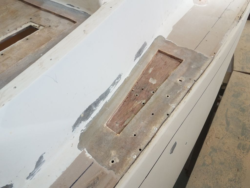
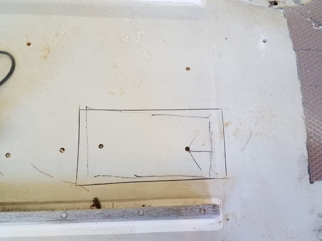
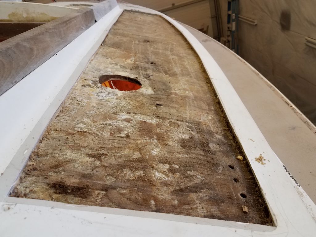
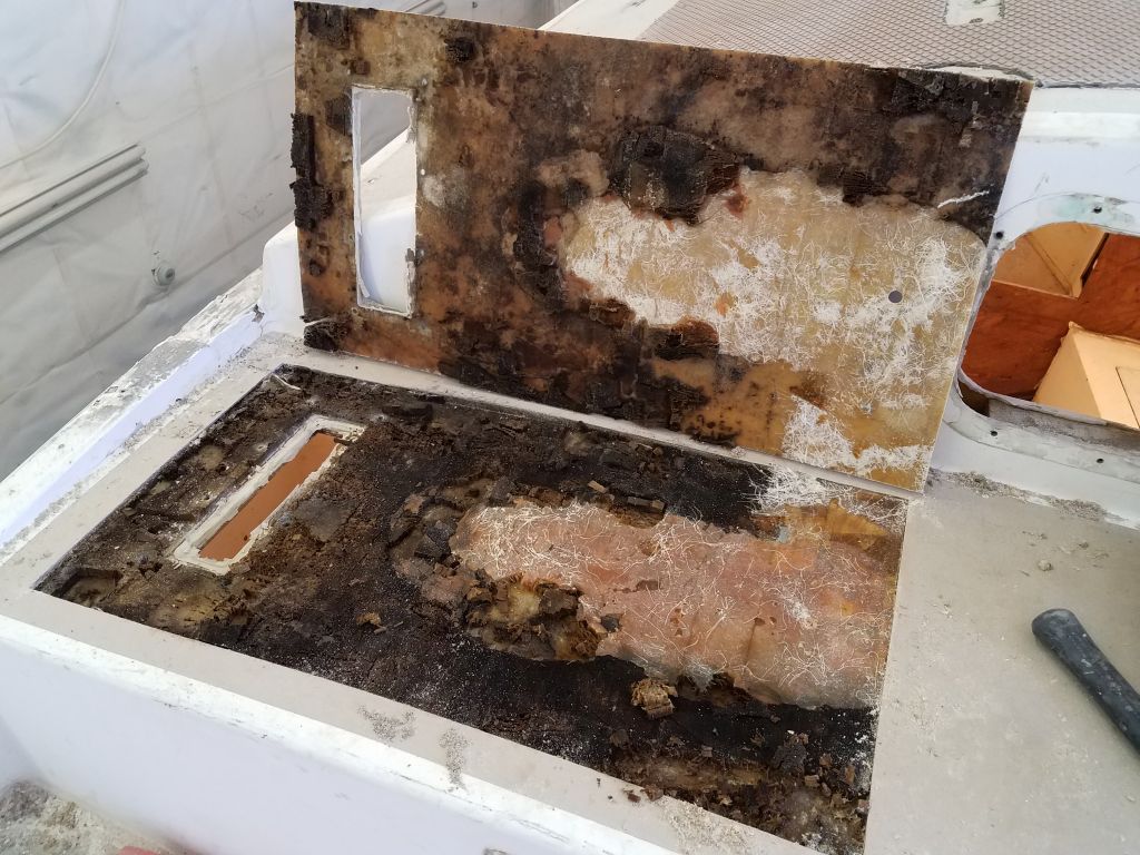
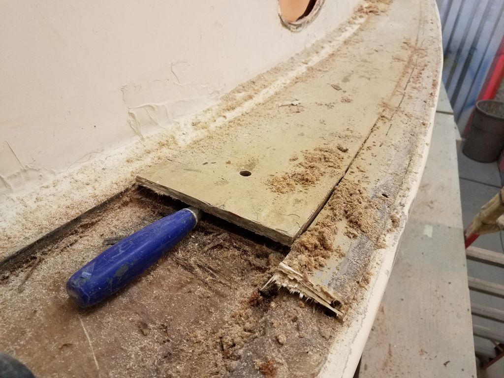
Now I needed to know what lay ahead for me with the port sidedeck. I was unsure of the overall construction, since it was all something done sometime after original construction of the boat, so I approached my investigation conservatively till I could get a grip on what was going on. Starting around the old water fill hole, which was an area that I’d be patching regardless, I cut a larger rectangle out of the deck top skin so I could see how easily the deck might come apart if needed. I avoided cutting too deeply or too extensively for now: this was exploratory surgery.
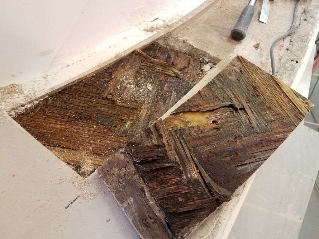
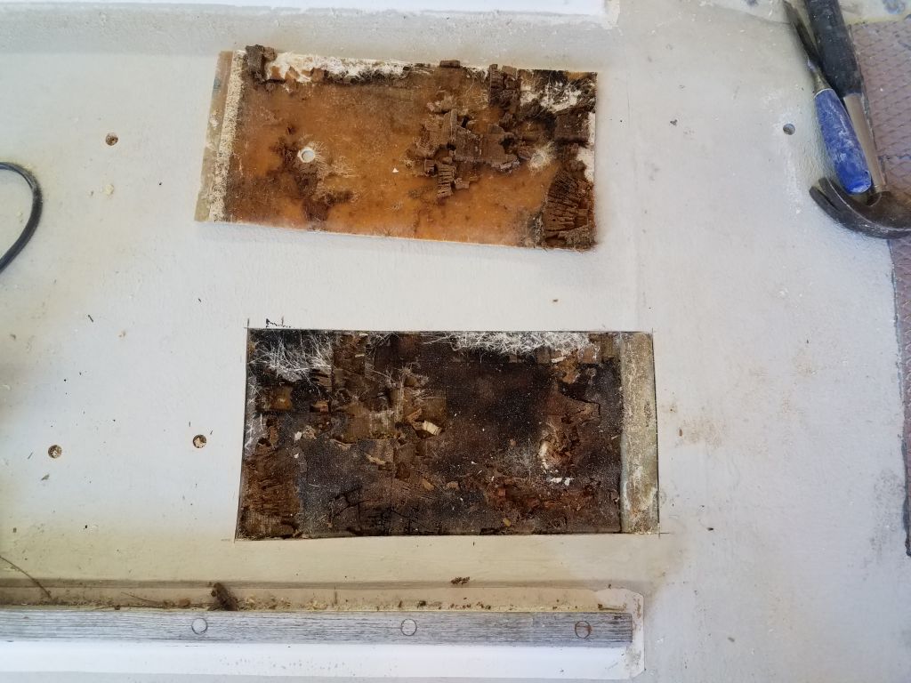
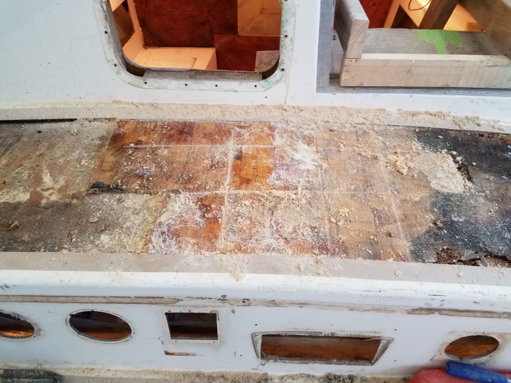
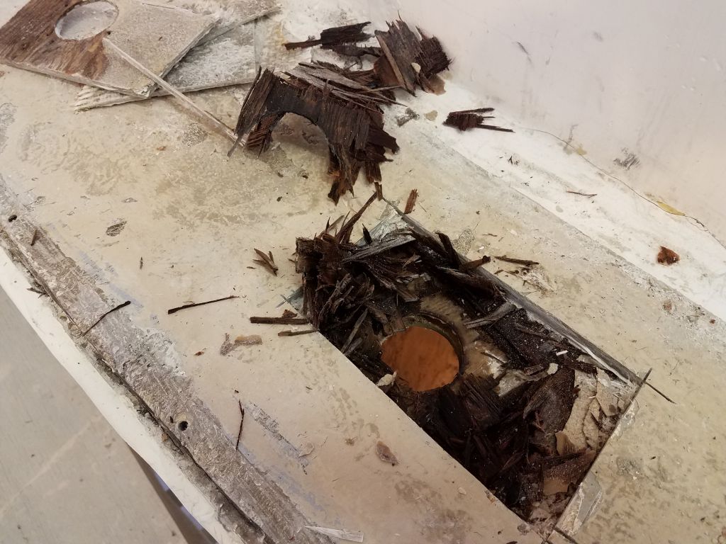
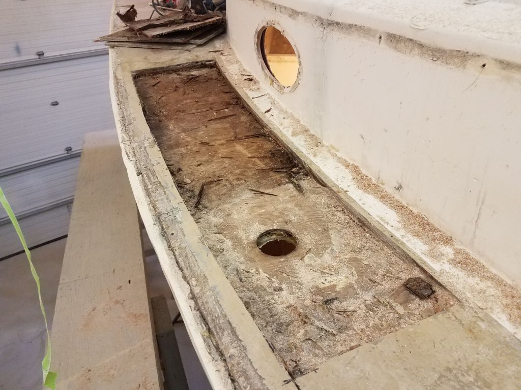
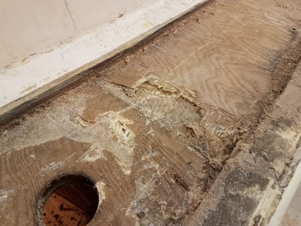
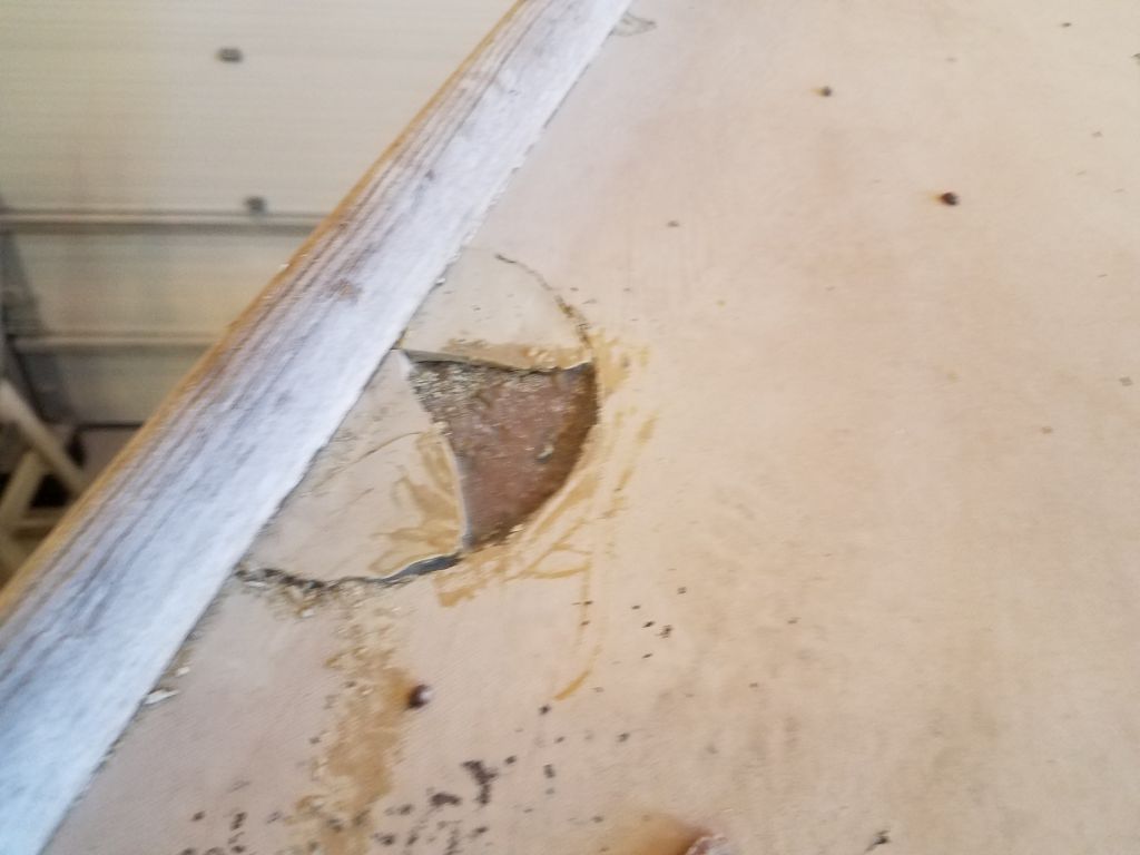
Removing the thick top skin–it was about 3/8″ of solid glass, clearly old-fashioned mat and roving in a dense resin-rich matrix–revealed the expected damp plywood core. The skin came up with relative ease and was not well bonded to the plywood at all.
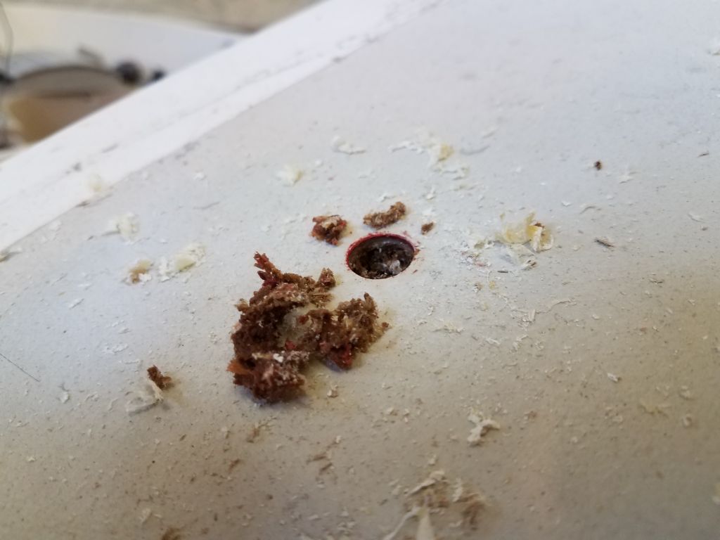
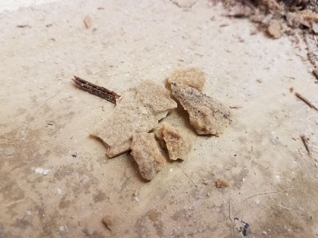
This area in particular, now and a little later in the process, revealed some strange material that looked to have been used as a filler or adhesive. It was reminiscent of sandstone, or hard brown sugar, and was brittle and friable in texture. I thought it might be remnants of a putty made from resin and wood flour.
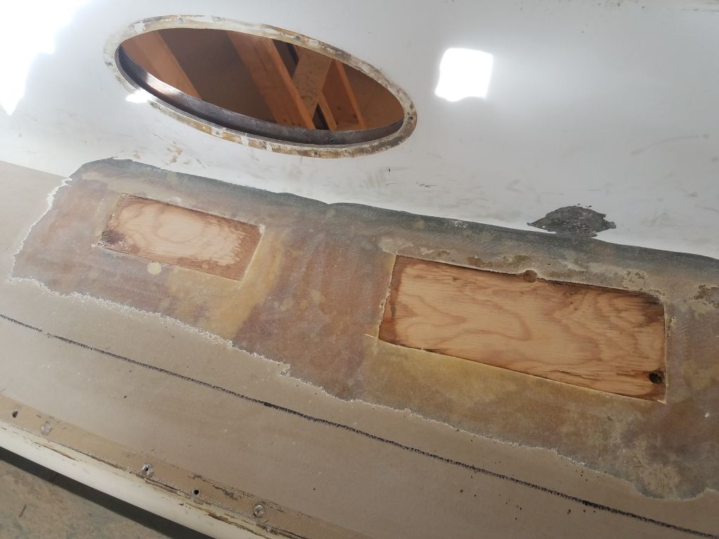
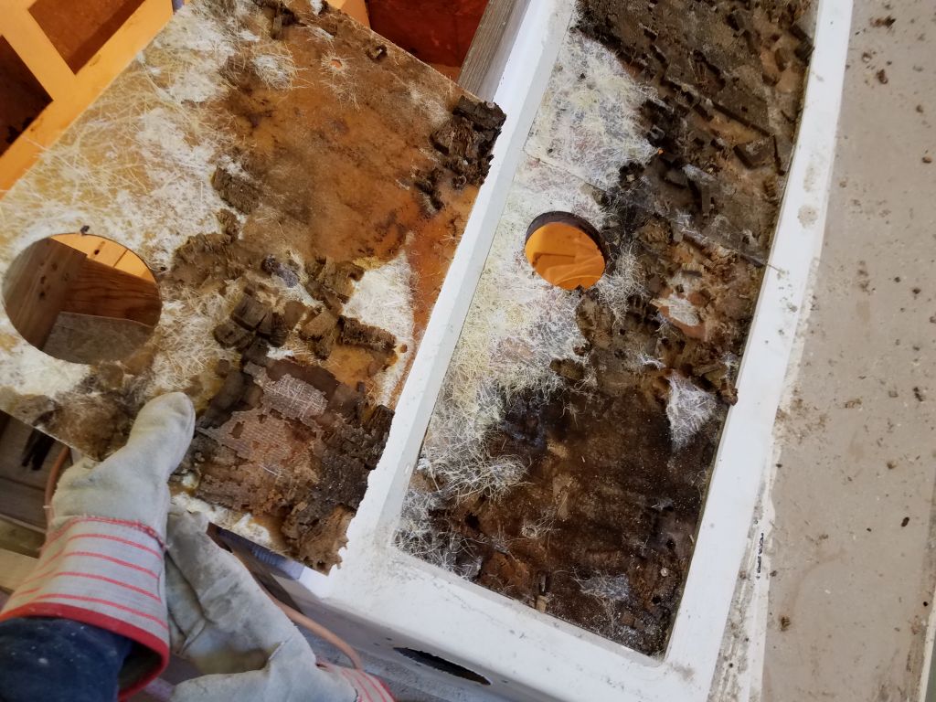
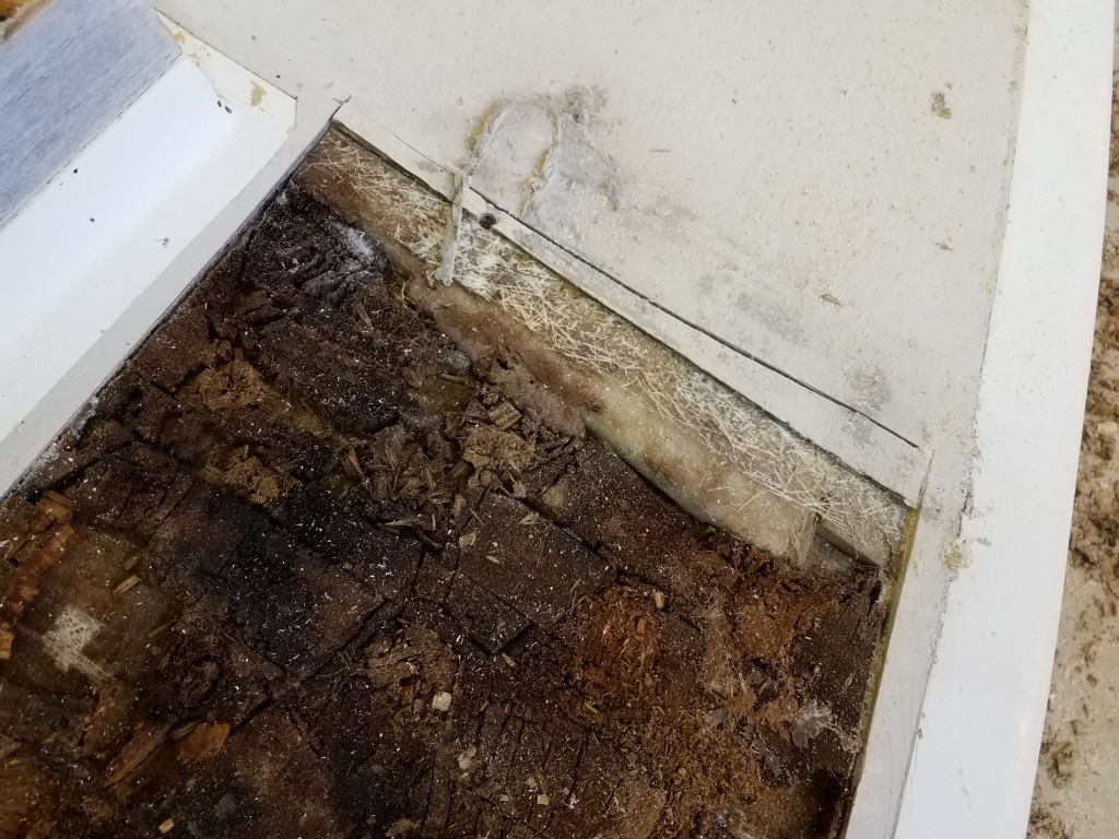
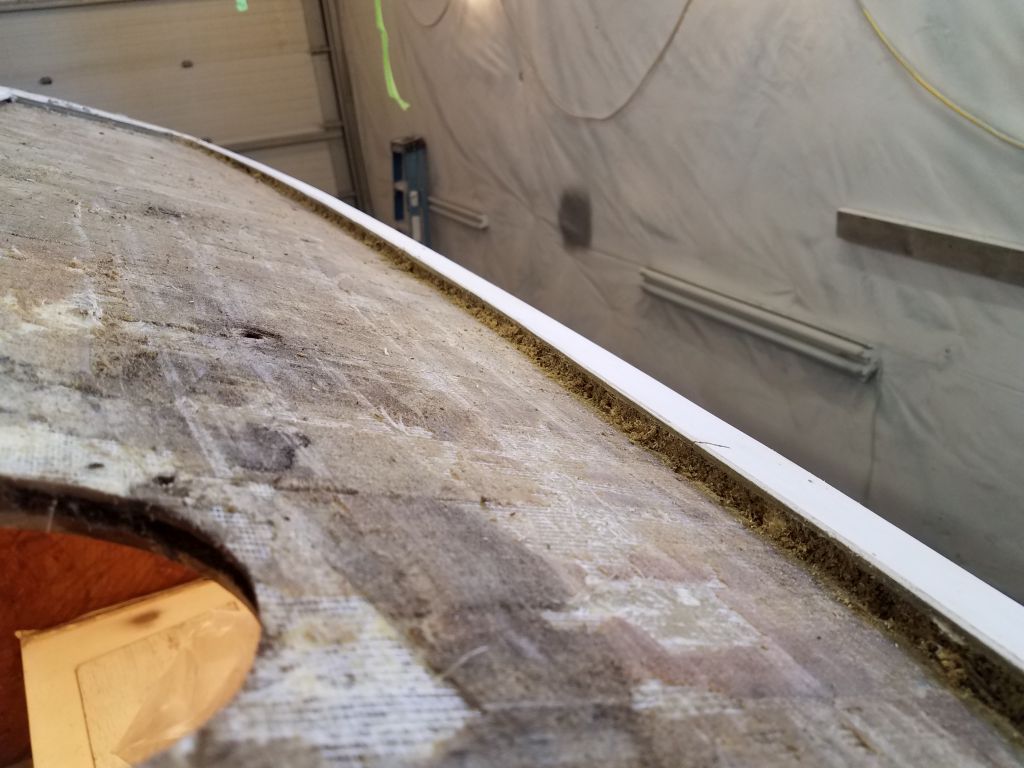
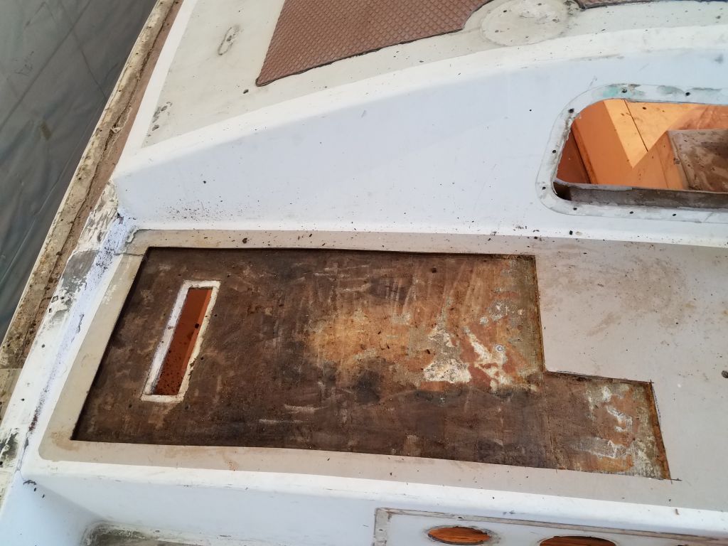
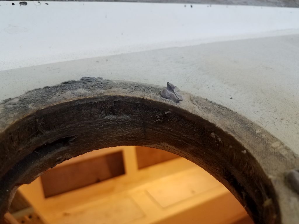
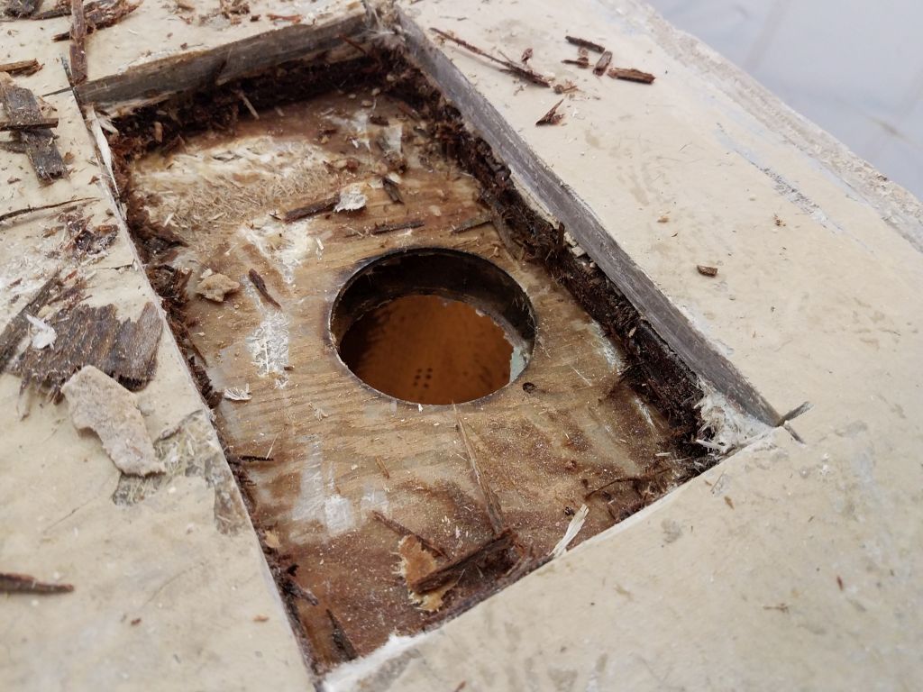
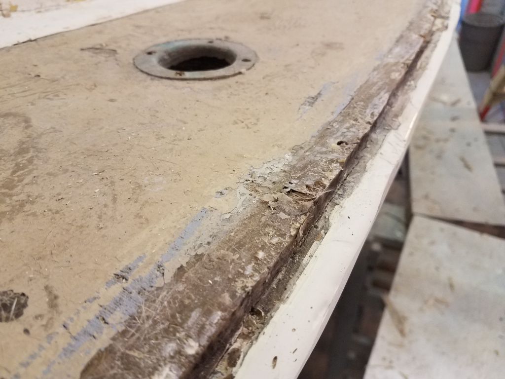
I wanted to see how far outboard the core in this area extended. All signs were that it was much closer to the deck edge than in the original parts of the boat, so I expanded my opening a bit to search for the edge, which finally turned out to be right at the inboard edge of the hull flange. I dug the core out of my still-small opening. Plywood can be much more difficult to remove than old balsa, but in this case, despite having to force my way through the laminations of the plywood–damp as it was it still had some integrity–there seemed to be virtually no bond between the core and the lower (or upper) skins of the deck.
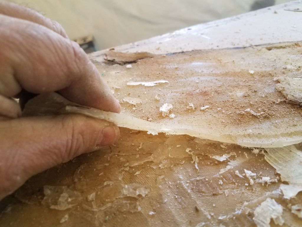
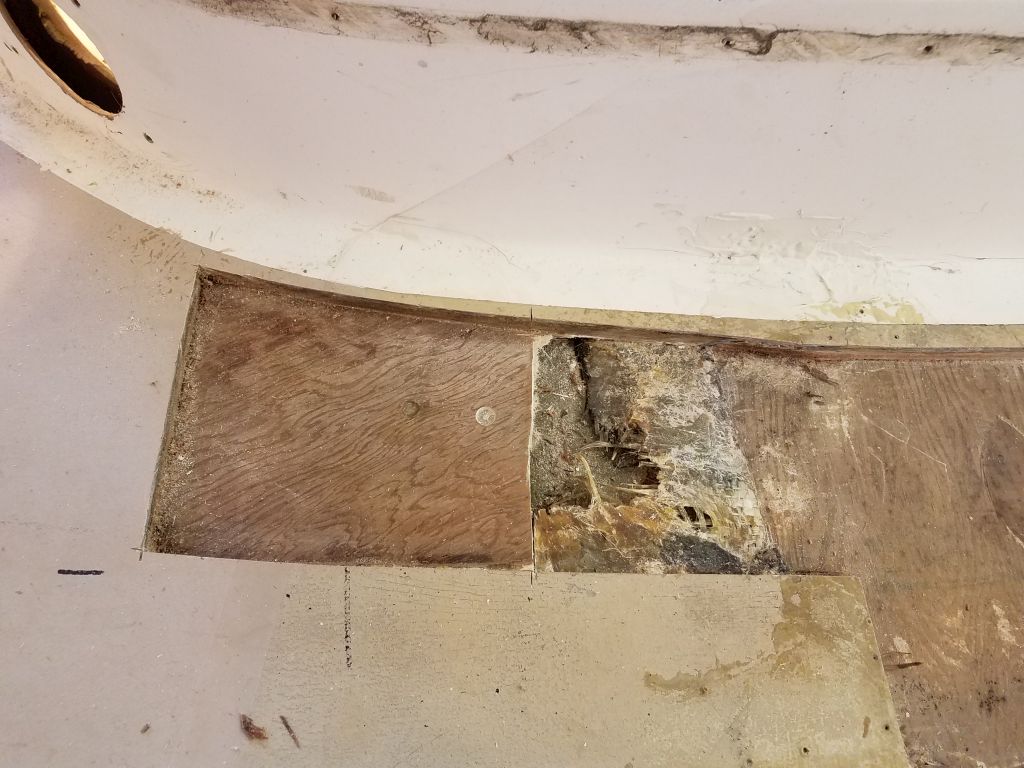
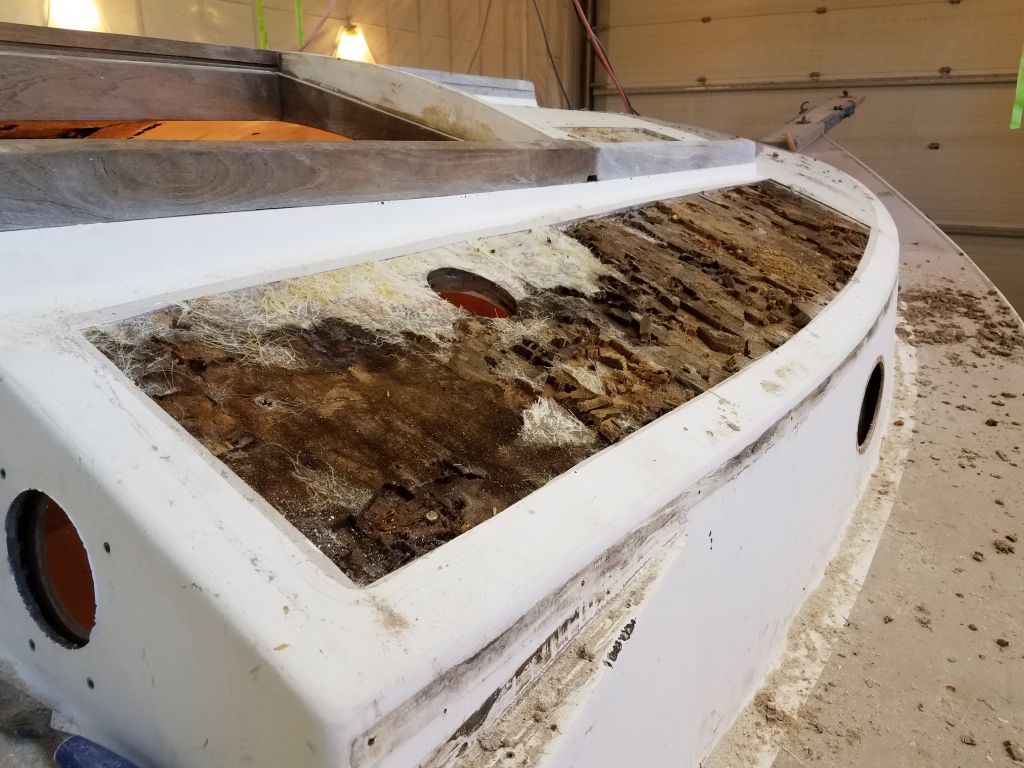
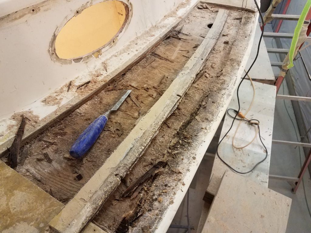
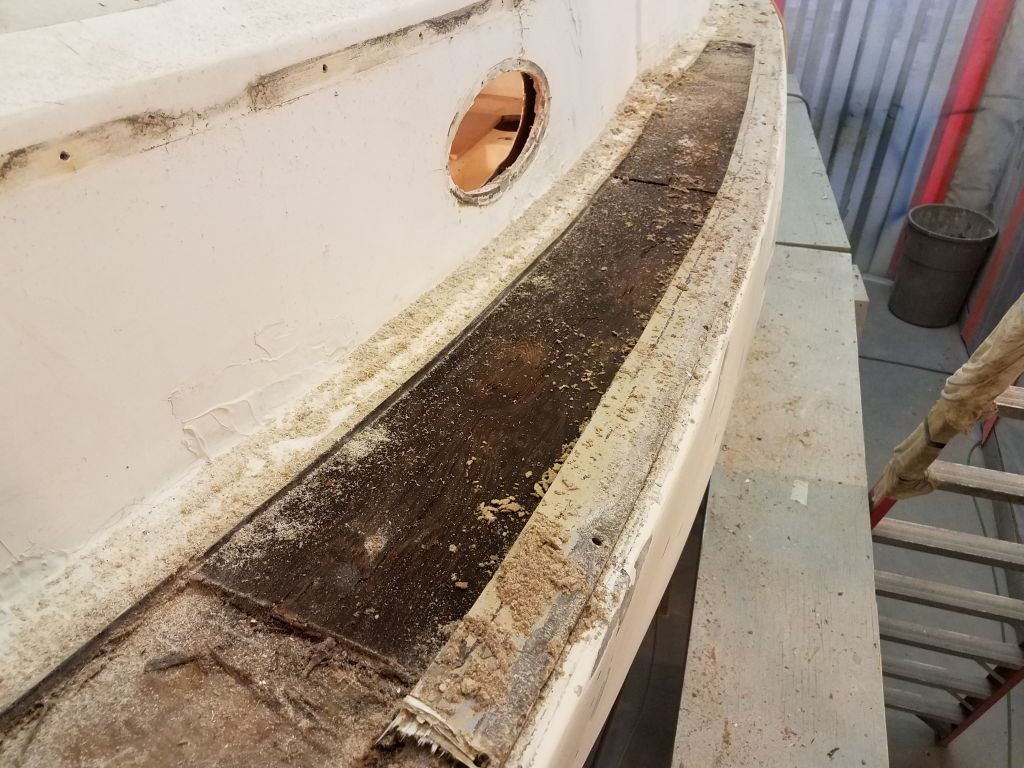
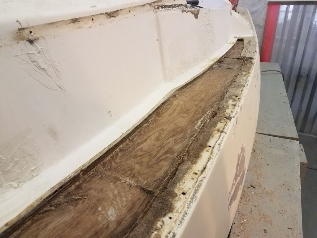
Now with a better sense of things, I expanded my cuts forward, extending past an obvious demarcation in the deck where this weird repair had ended. Once I’d made the cuts through the top skin and into the core, the skin lifted right off with nearly no bonding to the core beneath. Similarly, the core separated from the inner skin whole and without effort: there was simply no bonding remaining.
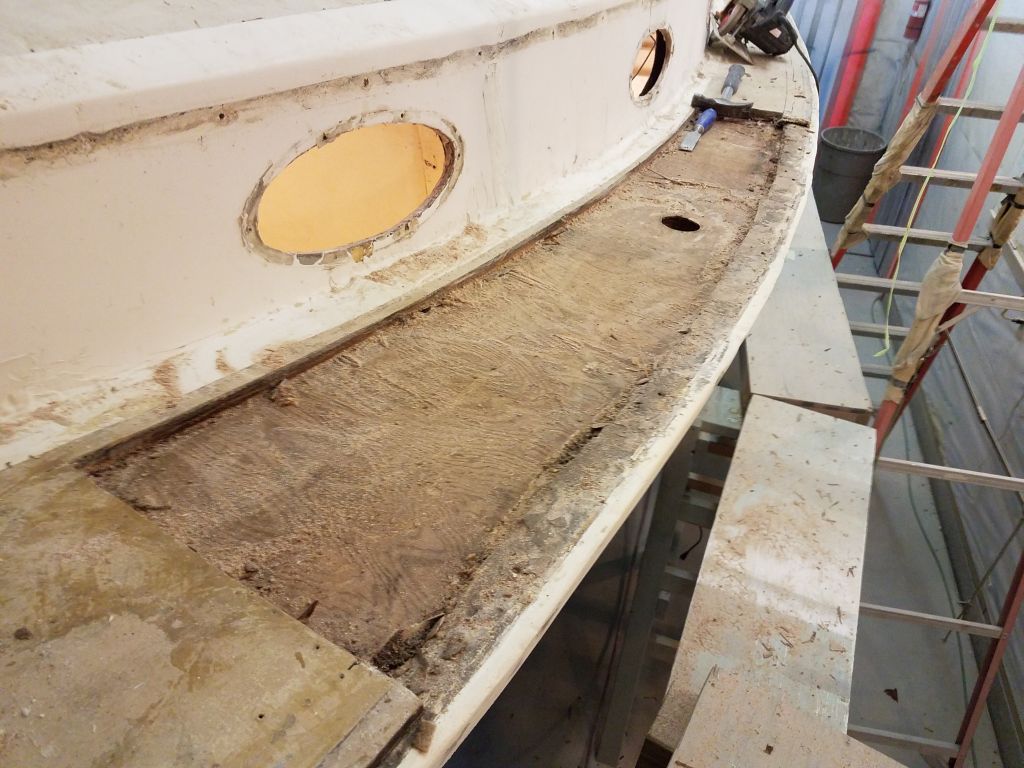
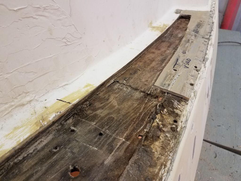
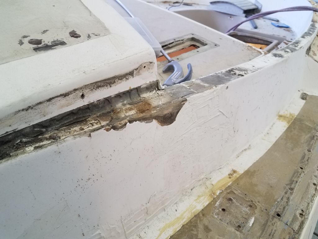
Though I left–and intended to leave–a 2″ or so wide band of the top laminate along the deck edge, I found that this laminate was not bonded to the hull flange in any meaningful way: any bonding that might have once existed had failed. This left the remaining strip loose and floppy, and this lack of bonding is what had led to the crack that I’d observed earlier at the edge of this very area. Whoever did this repair in the past had also fiberglassed the deck to the hull from within (this is why the liner had been partially removed in the cabin, all the signs of which were obvious while I was working down there earlier, though I didn’t understand the whole process yet at that time). So the bottom skin was secure, and the hull was still supported without the top skin, so with little choice I cut away and removed the small flange I’d left from the top skin. It wouldn’t be any harder–and would be a lot stronger in the end–for me to rebuild the deck entirely, while also incorporating additional tabbing to the hull over the area.
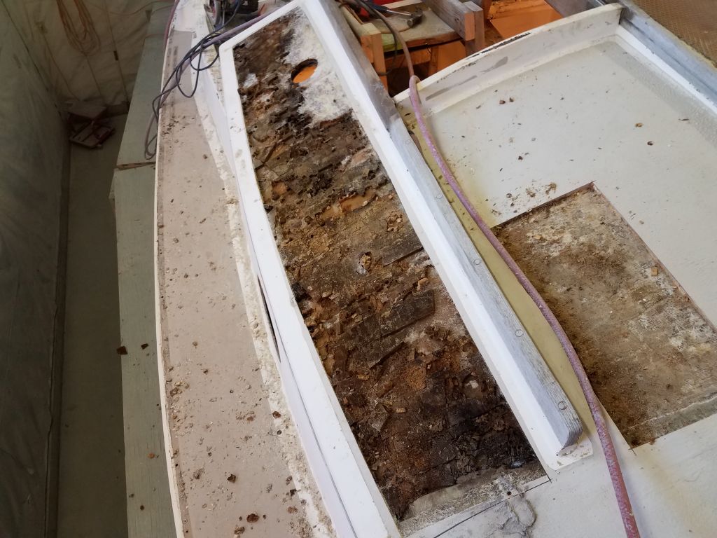
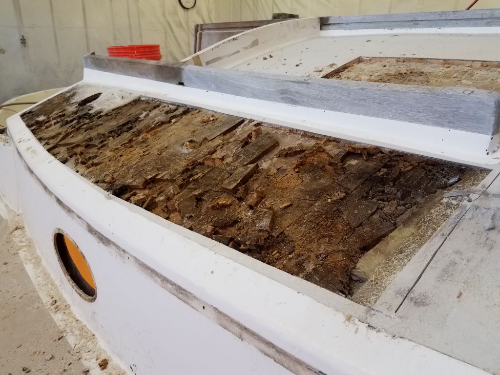
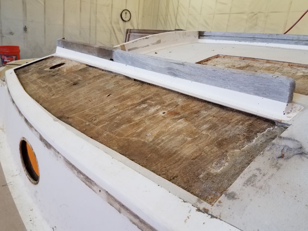
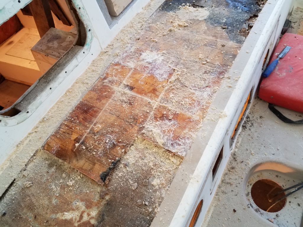
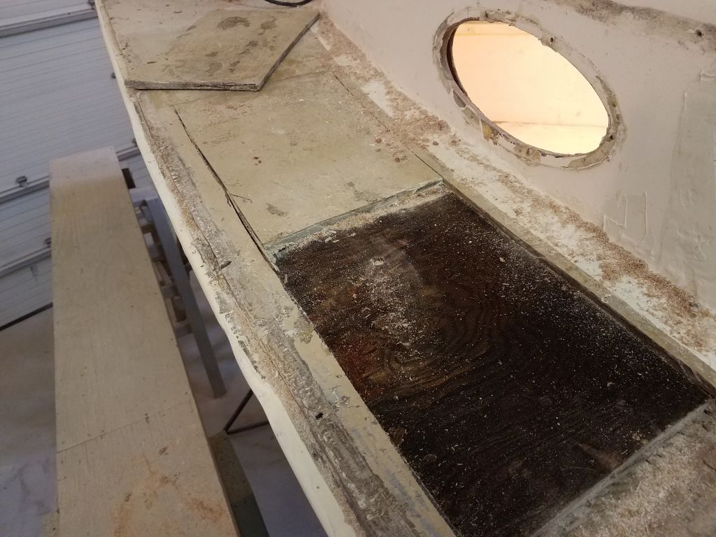
Moving aft, I continued the dismantling in this way. At first I kept the sections small, but it became increasingly clear that there was just no bonding at all between the compoents, so I was able to remove the last section in one large piece.
The video is rough, since the work was the priority, but it shows how easily I could pull up this large section of skin once I started with a small chisel.
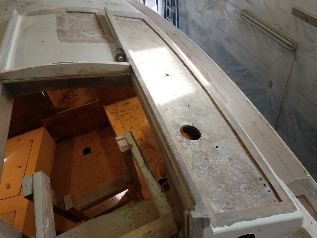
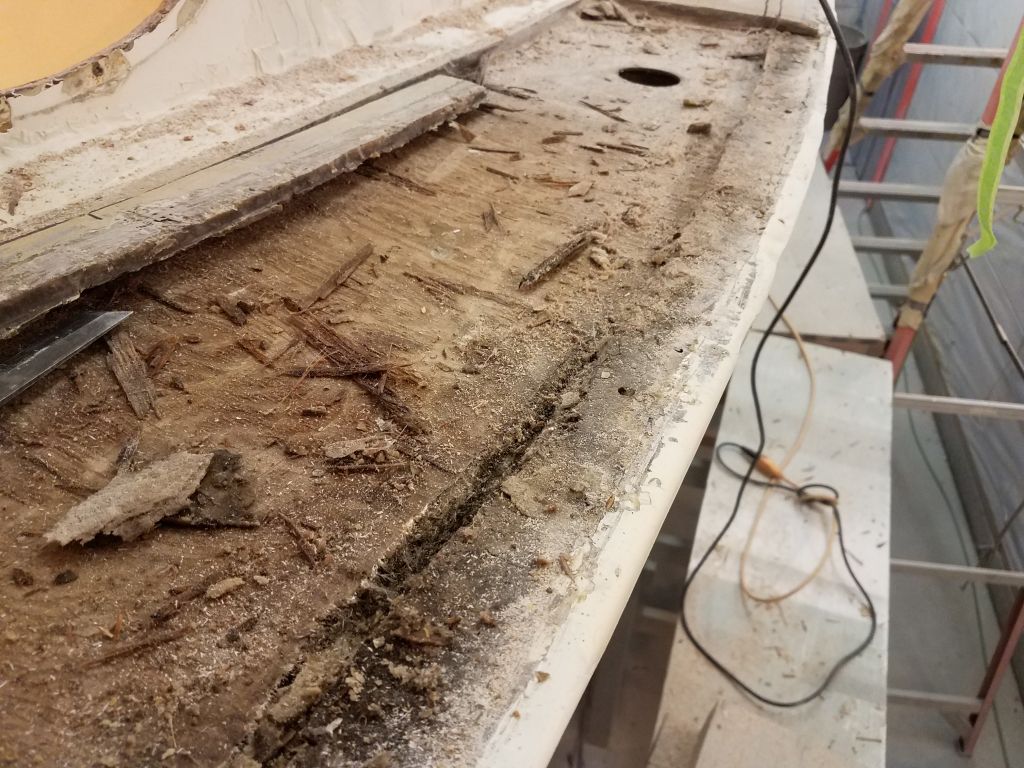
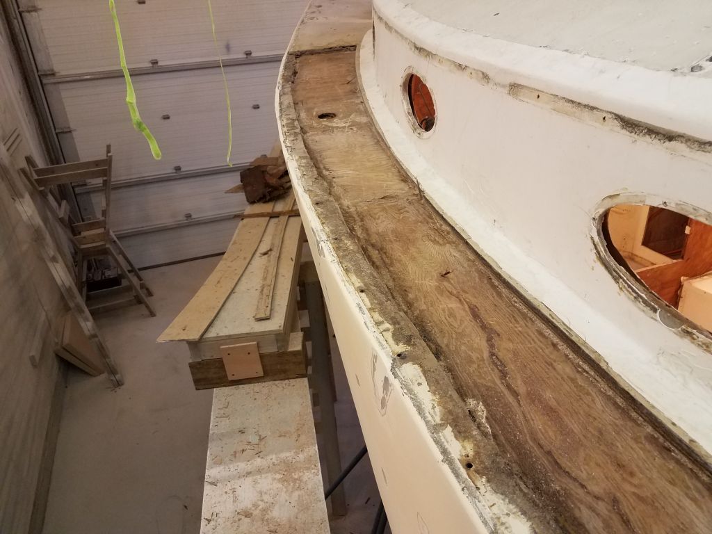
At the aft end, I extended the cut as far aft as I could, though here the cored area was original and much narrower overall.
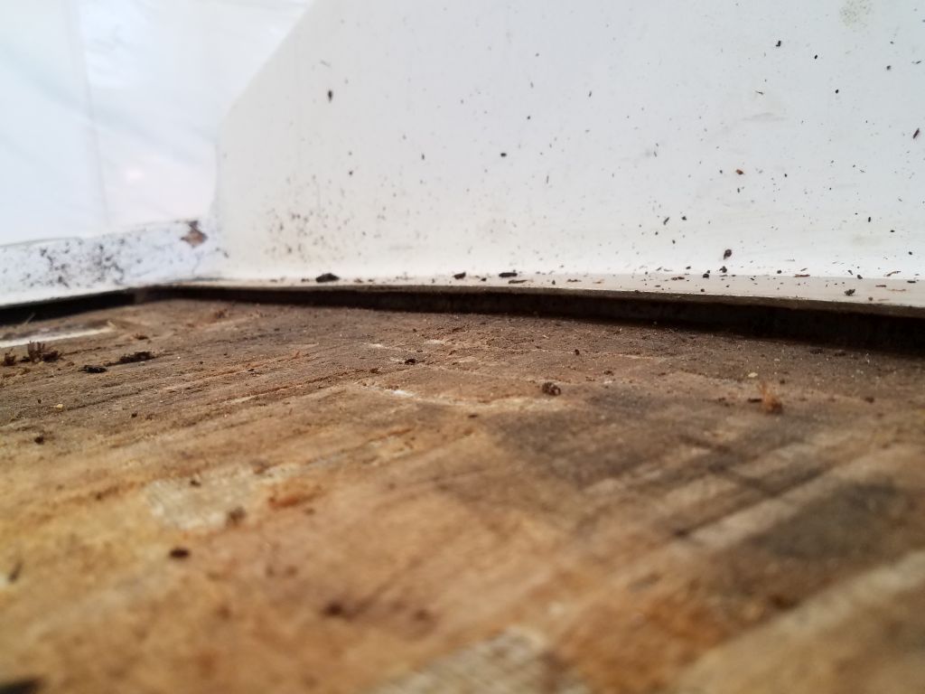
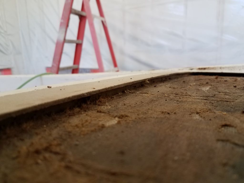
There was a sort of elevation change in the bottom skin just aft of the water tank fill location. Overall the bottom skin was in good, sound condition and would tie in well with the repairs to come. The appearance of plywood grain on the bottom skin is just the remnants of the imprint of the core when first installed.
Though I’d approached this sidedeck with trepidation, in the end I felt much more positive. All the suspect old work was gone, and what remained would be something I could easily rebuild in a stronger and superior manner. It’s always the unknowns that are the worst. With the worst and ugliest section of the deck now opened up and ready for new work, I looked forward to getting on with it.
Total time billed on this job today: 6.25 hours
0600 Weather Observation: 13° (this is just too cold for April), clear. Forecast for the day: Sunny, then increasing clouds and snow late in the afternoon, around 40°
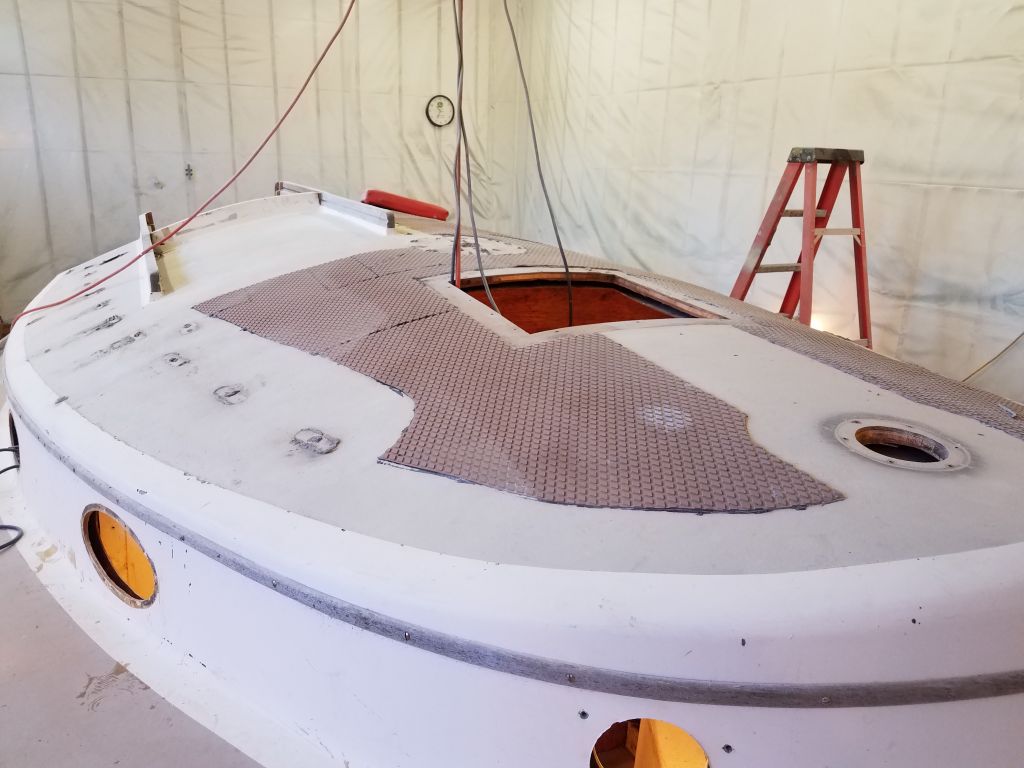
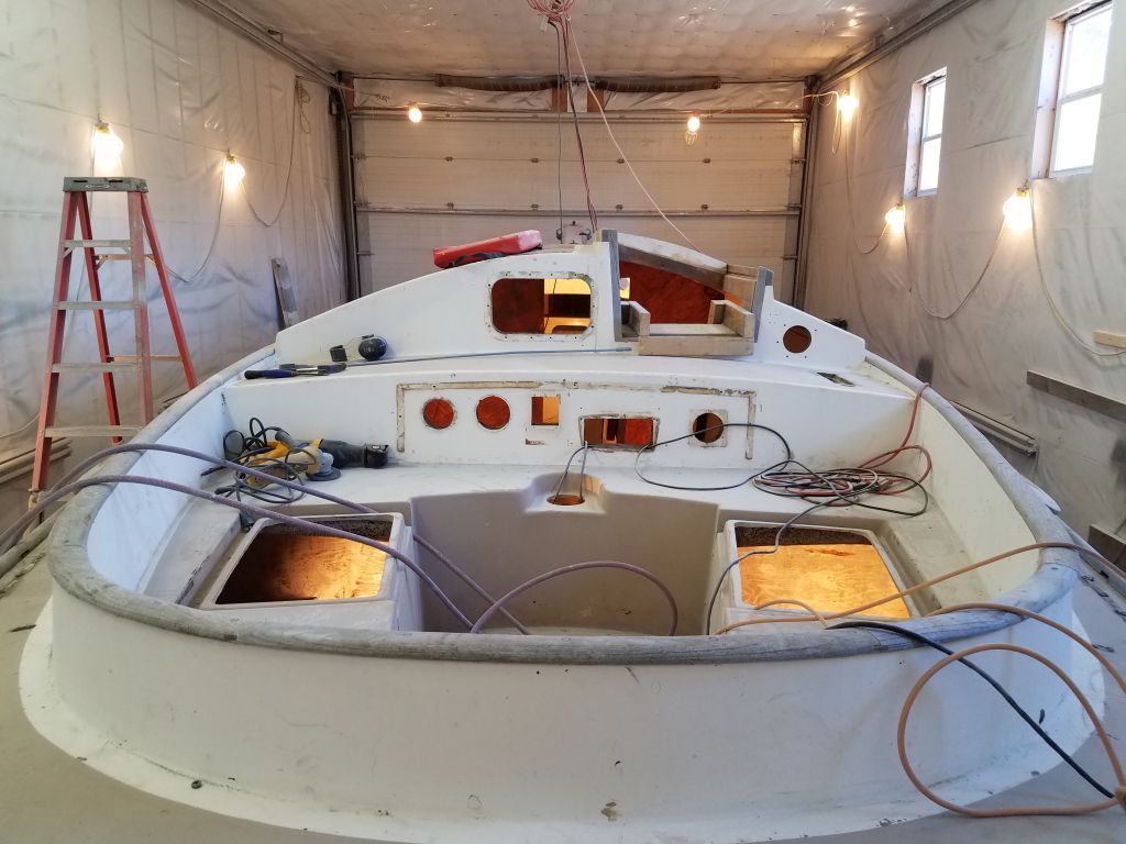
After a morning appointment, I got to work on the decks, where I expected to spend a lot of my time in the coming weeks. I began with an overall visual assessment of the deck, something I’d done over and over every day as I worked on other parts of the boat, but now it was time to really dig in. Whatever incident (s) had traumatized the poor port side of this boat might never be known to us, but clearly there’d been a lot of work here in the past, both on the hull and on the decks. The port sidedeck was a terrible looking thing, with too many horrors to document properly. Would it end up being sound despite it all?
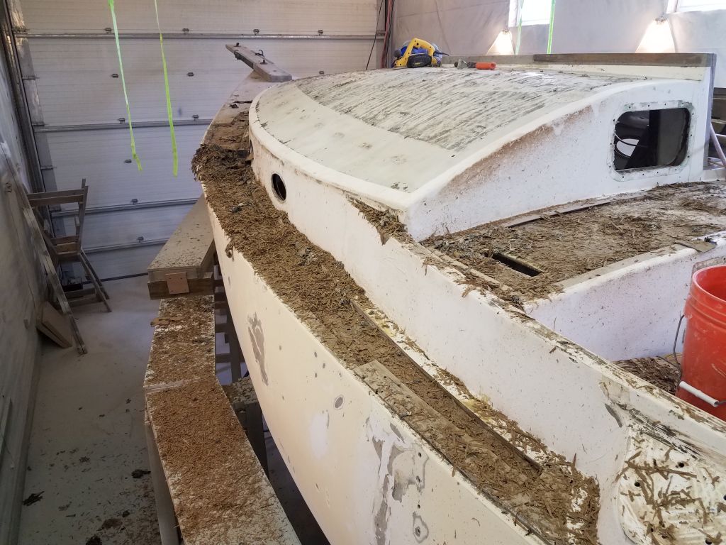
The sharply cambered coachroof looked to have had repairs in the past, probably core replacement. Much of the surface was covered with Treadmaster applique, hiding the true condition for now, but from various angles it was clear that the previous repaired had felt that fairing was for fools. There was ample fiberglass weave still showing in the non-Treadmastered areas, and a rough edge near the corner of the cabin trunk. At a minimum, this area would need a lot of coatings removal and refairing; time would tell how successful the previous core repair had been. I’d remove the Treadmaster as well.
The forward portion of the starboard side of the coachroof had been worked on at the same time, judging from the basic appearance, but the narrower strip leading aft outboard of the companionway appeared original, and while I’d not yet done a detailed deck inspection and core sounding, earlier while working on something else I’d noticed some softness here.
The starboard sidedeck and most of the foredeck appeared to be original, which was probably a better state of things in this instance.
The cockpit well, in original form, seemed generally sound so far, though there was some top-skin delamination here and there (just like on the poop deck around the new hatch opening). After many trips back and forth across it over the past weeks, I already knew that the core in the large bridgedeck was completely ruined and would require replacement.
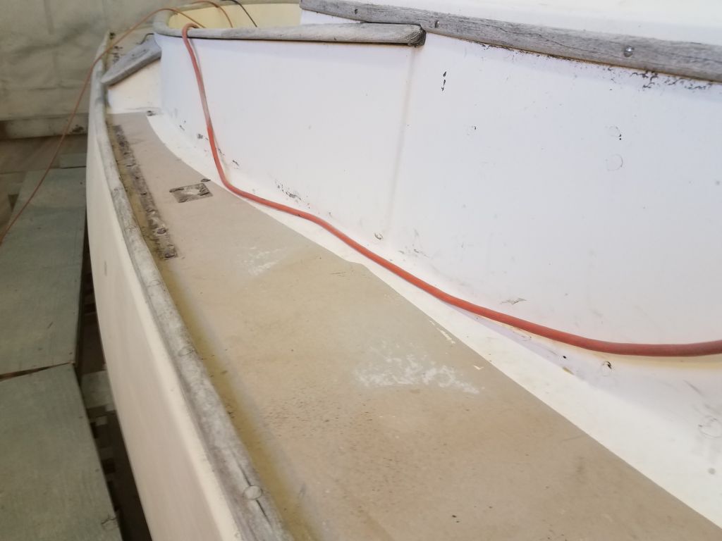
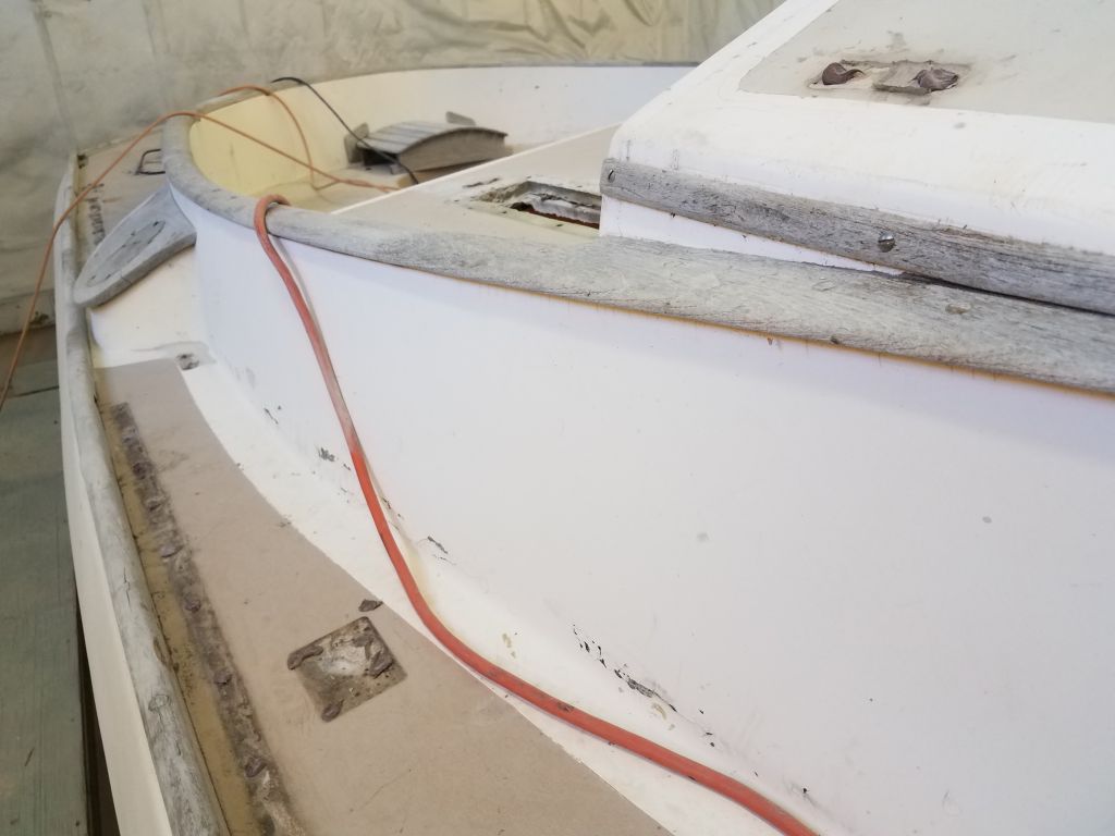
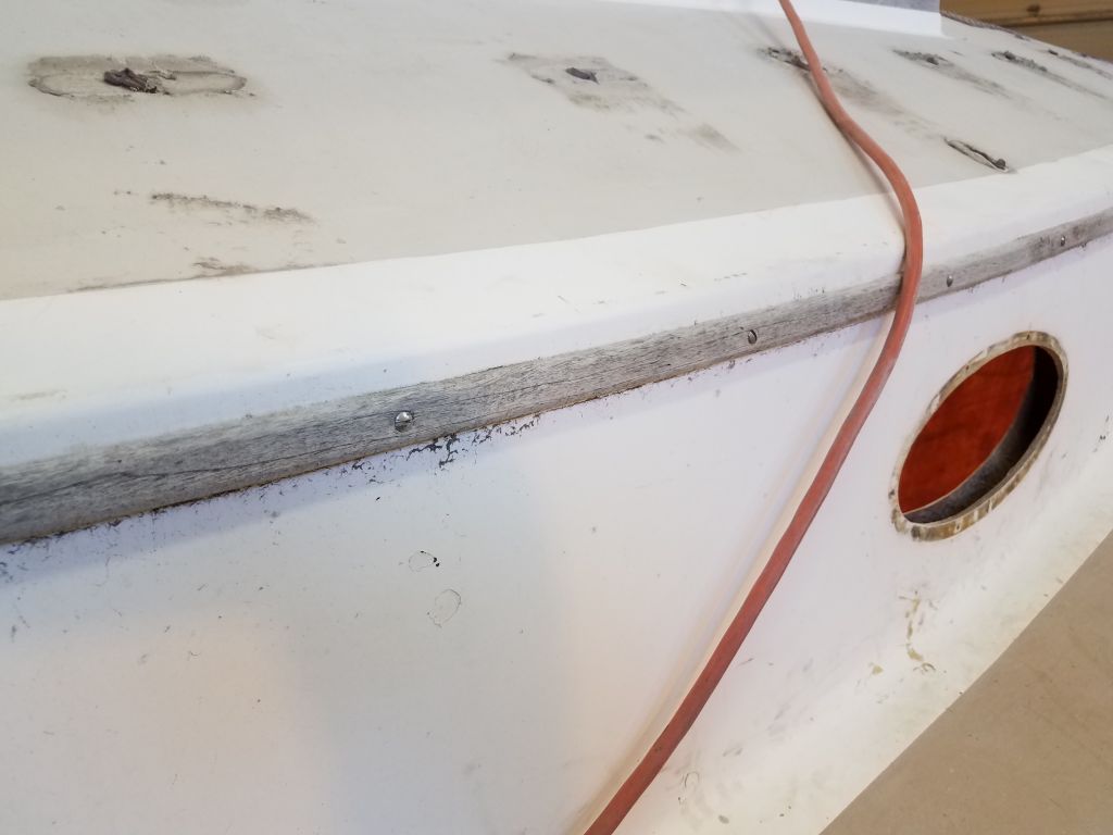
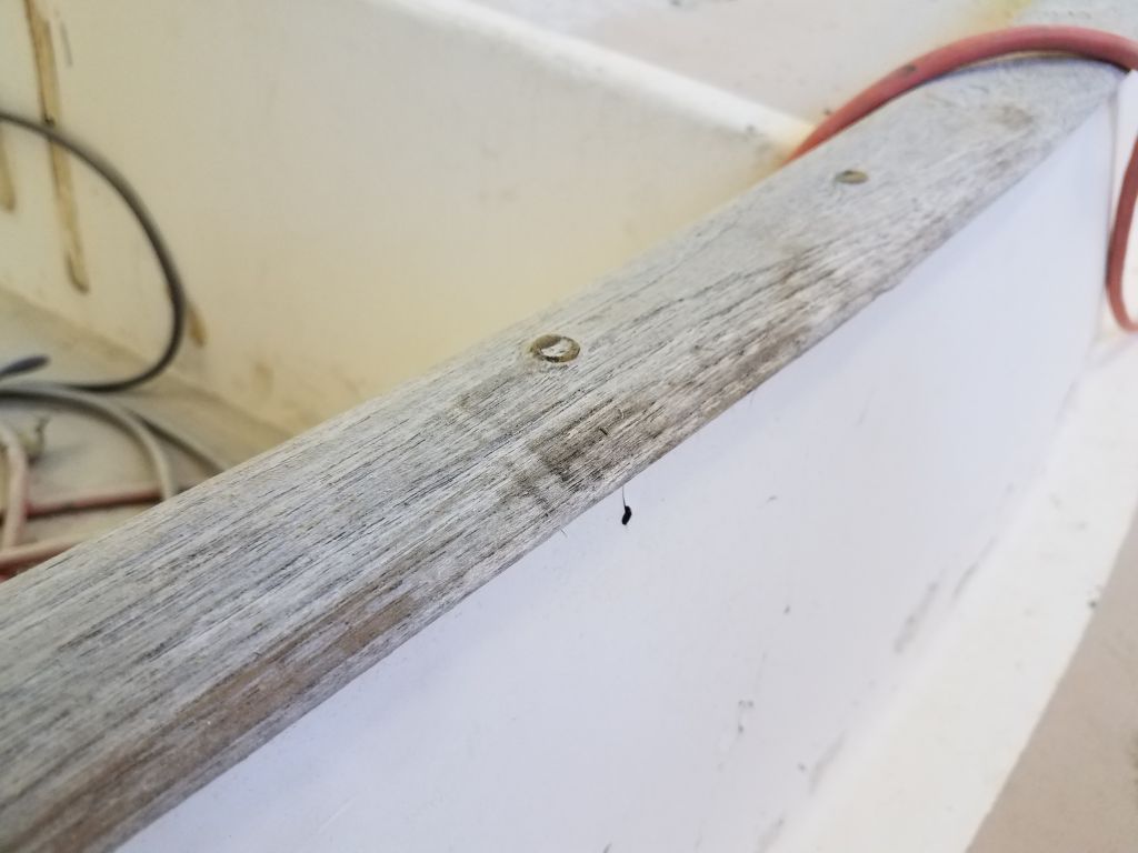
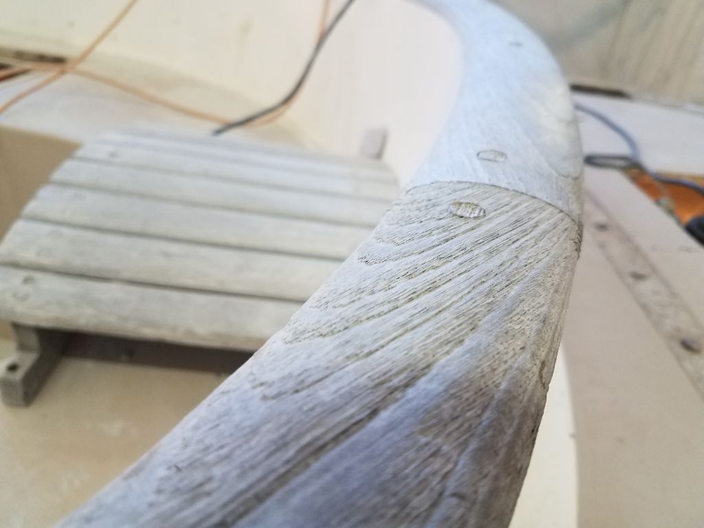
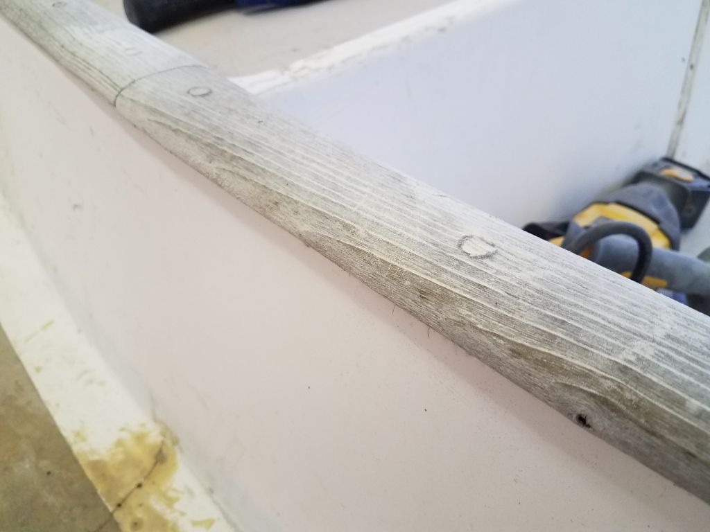
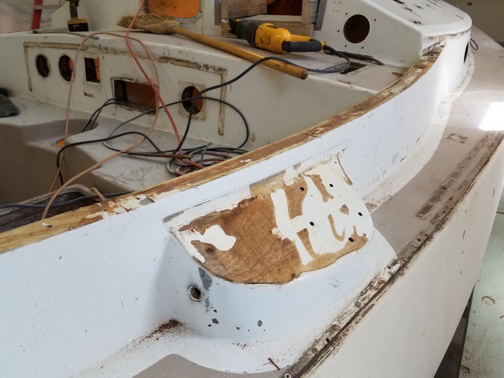
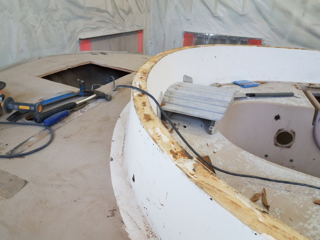
Now I got to work on the toerails and other deck woodwork. Since the beginning of the project, I’d considered whether or not to remove all this wood, or whether it could be salvaged as is. In the final analysis, though, I knew all along that it would all have to be removed, partly to ensure proper access to all areas of the deck in order to properly complete the substantial list of repairs and cosmetic improvements. Plus, the woodwork itself was just marginal at best: heavily weathered, with some splits and checking (port toerail), missing bungs and exposed fasteners, and just a lot of hard, protruding grain that would never be restorable satisfactorily. Things that seem OK at the onset of a project always fade quickly into unacceptability once the adjacent areas get spiffed up.
Then, even if the existing woodwork had been OK as is for other reasons, there was the fact that the toerails, at least, were clearly leaking through the fasteners in many areas, as evidenced by staining on the hull in regular intervals in exposed areas inside. Never mind that some of the repair work and upgrades might require removal of the wood in their own right, particularly since I wanted to ensure the integrity of the hull/deck joint on the port side. Off it would come!
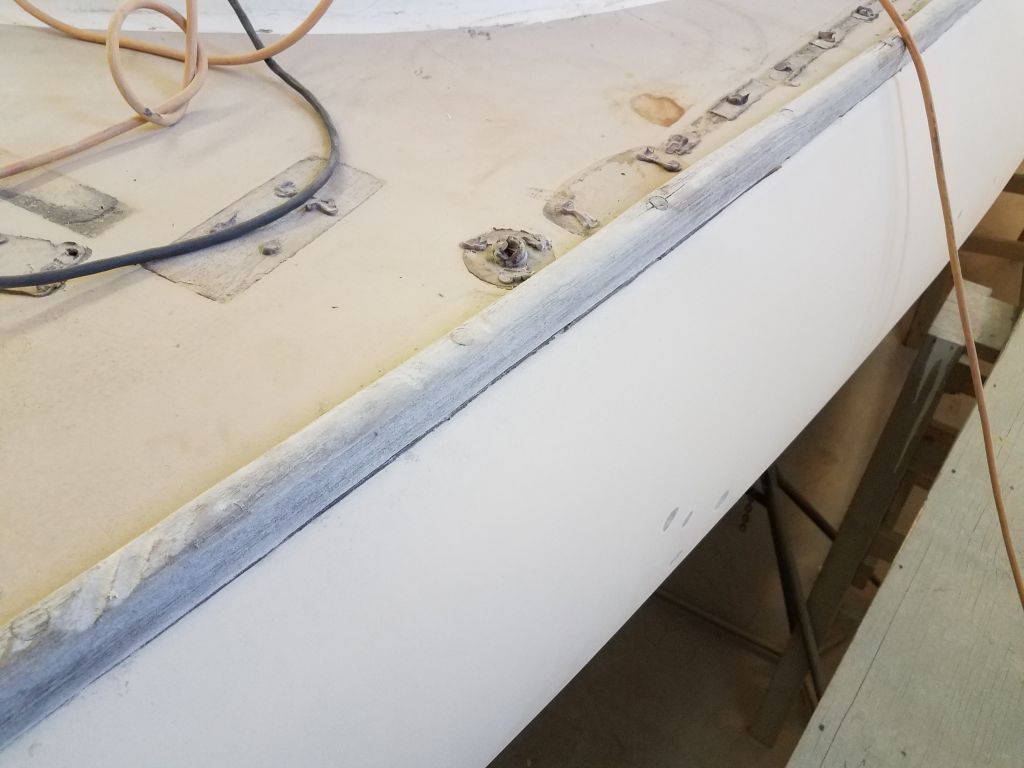
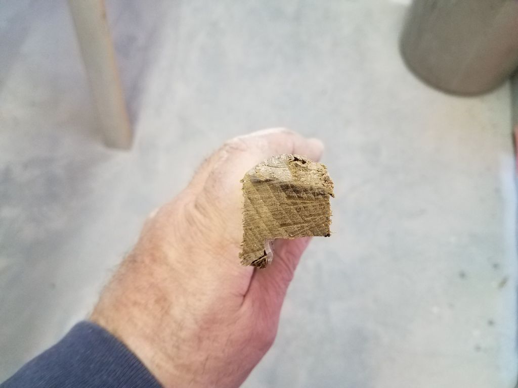
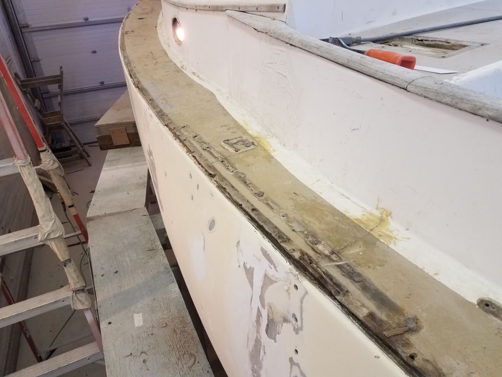
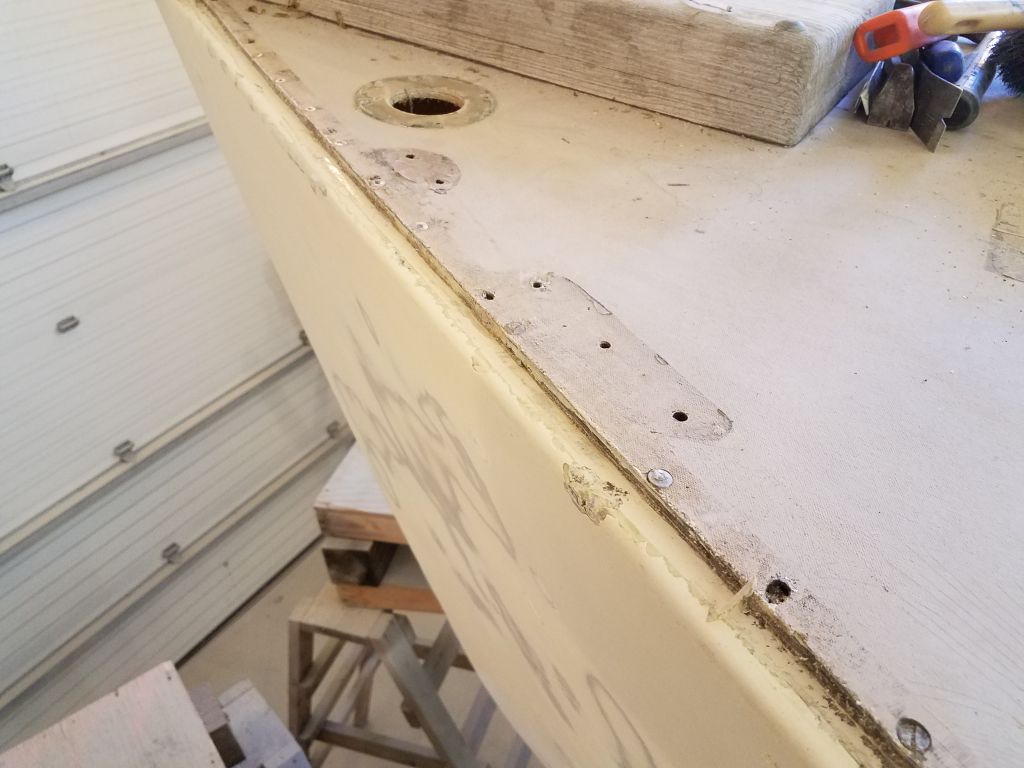
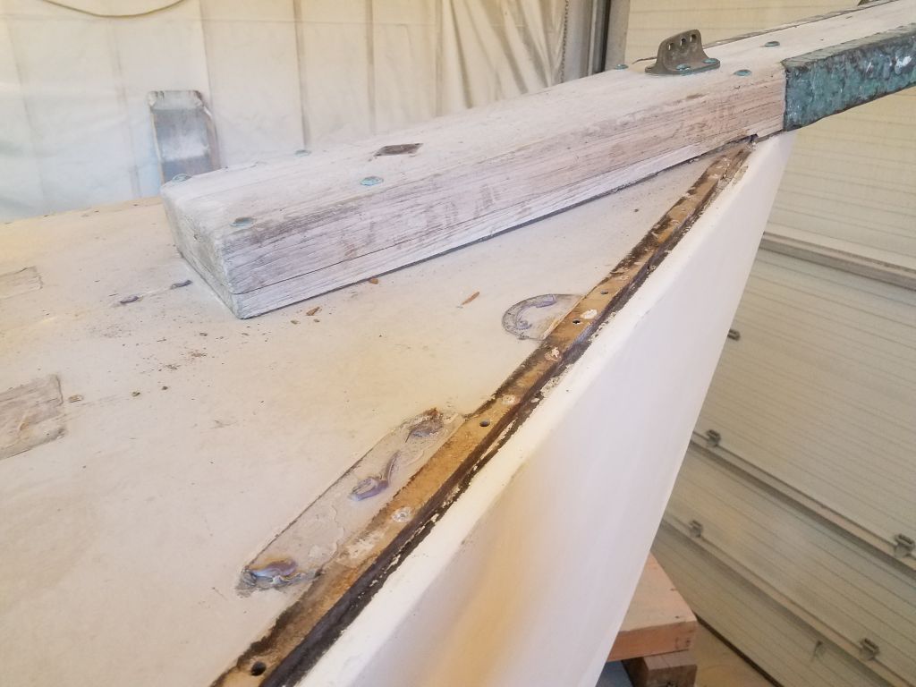
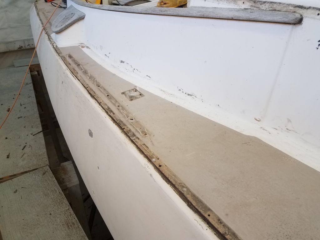
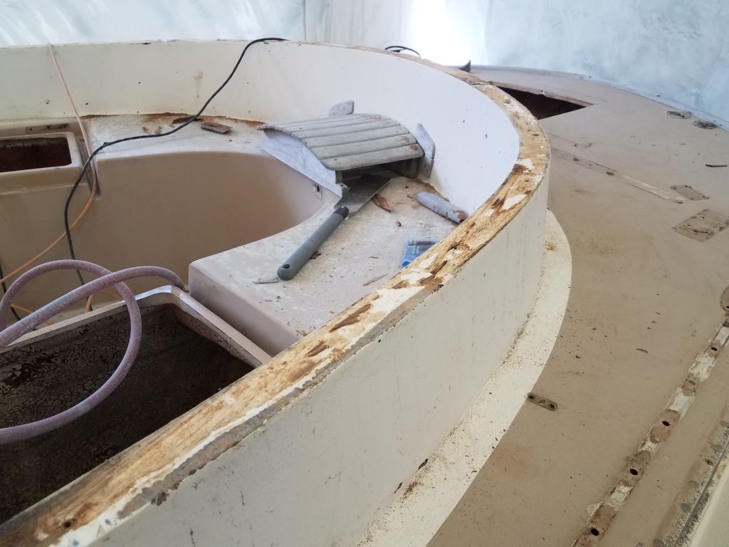
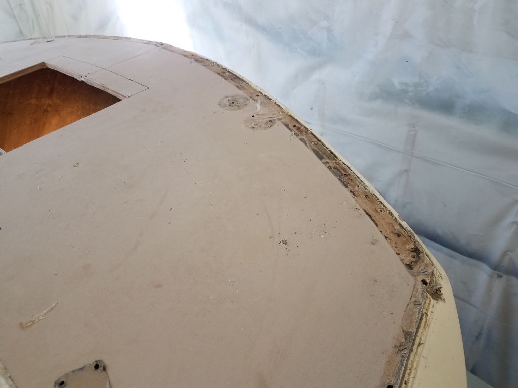
The toerails were installed with stainless bolts through the deck. I never even considered trying to carefully undo these bolts, which would have taken me days to complete. I started with the port side. With no need to save the rails, I used a saw to cut through the rail at each fastener location, sawing off the fastener head so I could easily (relatively speaking) pull the rail up and off in most cases. The rails were heavily bedded in silicone, which might not have done a great job actually preventing water from entering, but at least it was difficult to remove. I saved a few pieces of the existing rail for future reference. I pushed the fastener studs through into the interior for later removal.
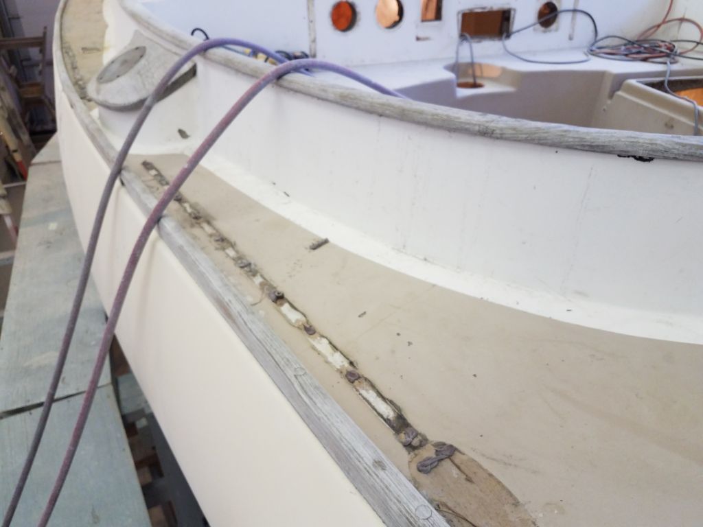
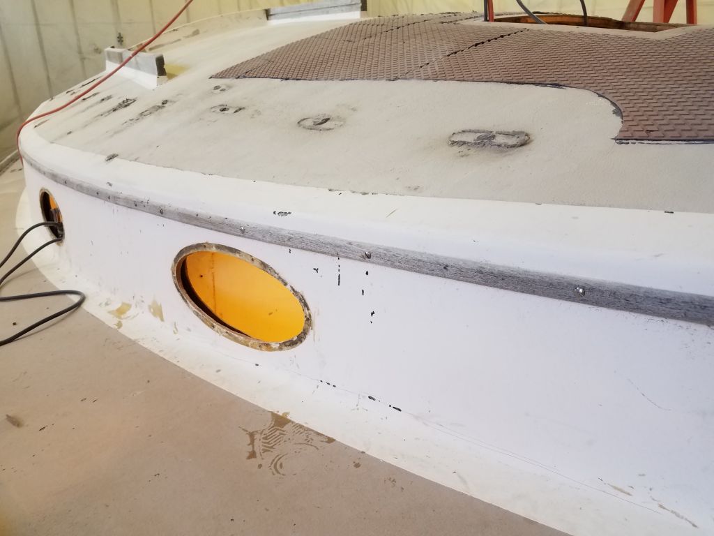
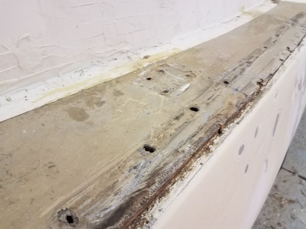
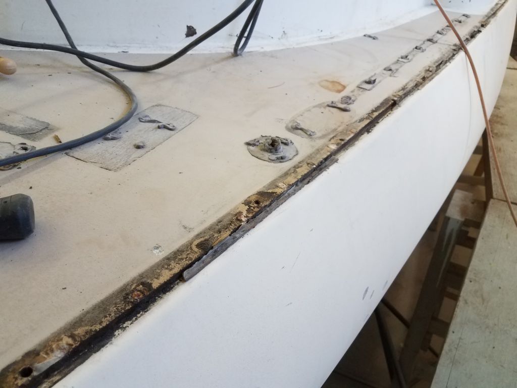
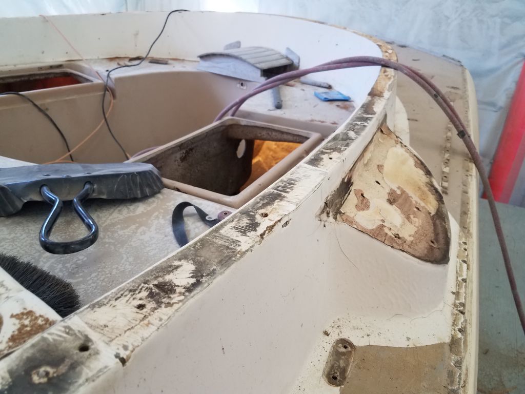
As expected, the deck molding rested atop an inward hull flange, creating a small edge there. The rails had been notched to fit over the lip and hide it. The deck was secured with rivets and some sort of sealant, and while the toerail bolts had gone through the flange, they weren’t alone responsible for holding the boat together.
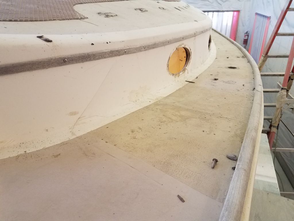
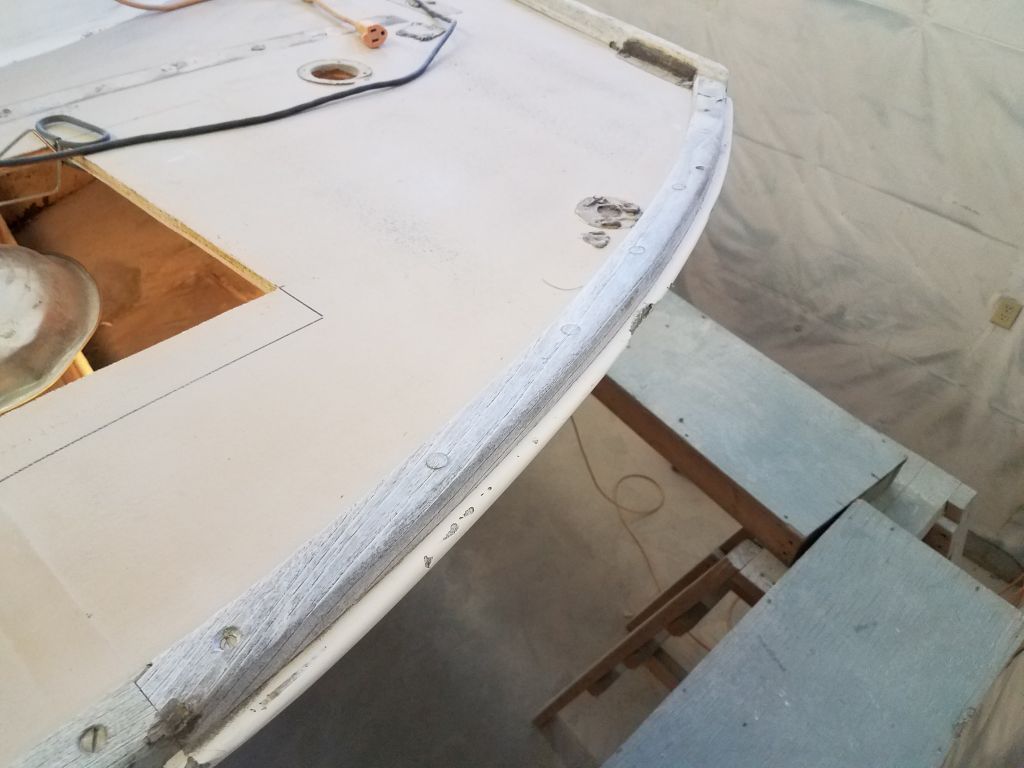
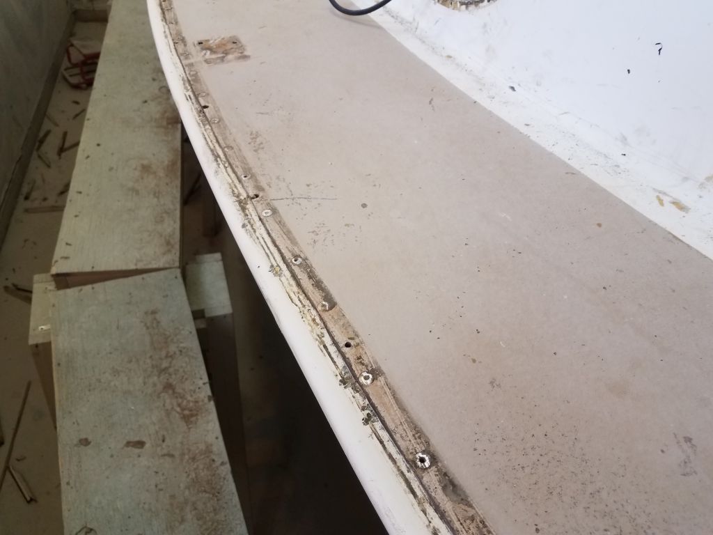
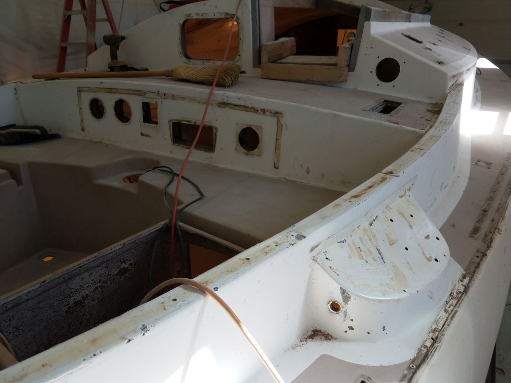
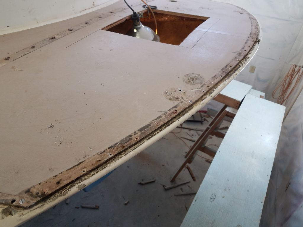
Once I’d removed all the wood, I scraped away the worst of the old silicone from the edge of the deck. While some of the newer work over the amidships portion was a bit rough, it didn’t appear there were any horrible structural findings yet either.
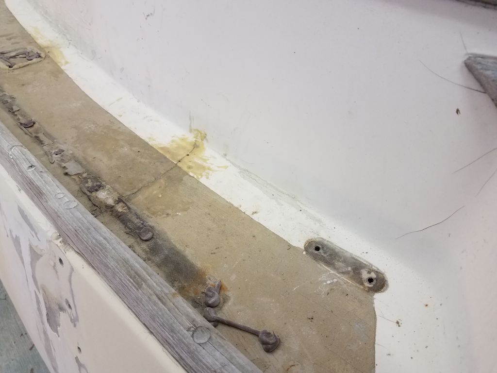
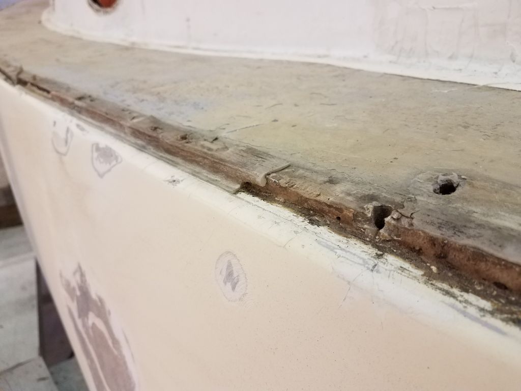
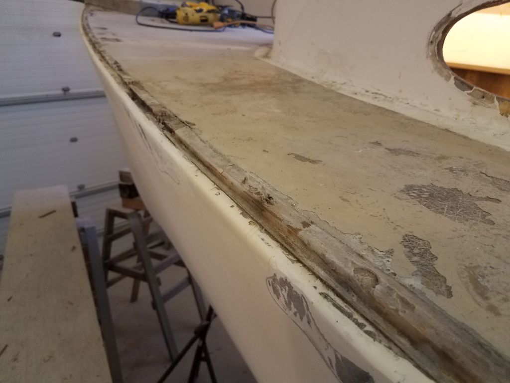
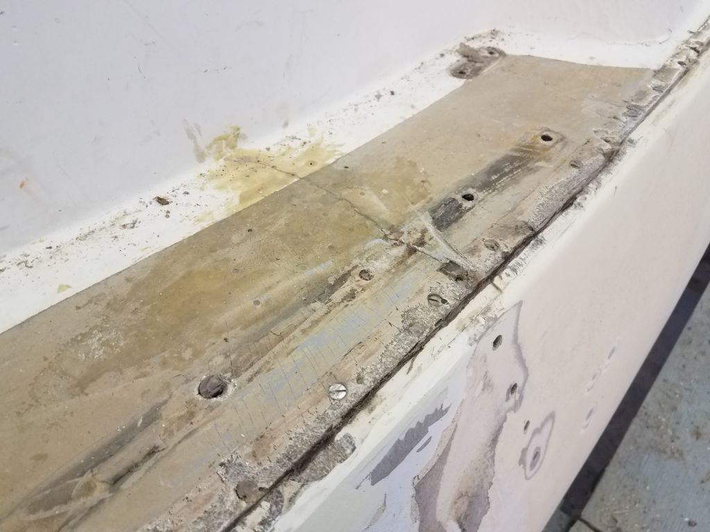
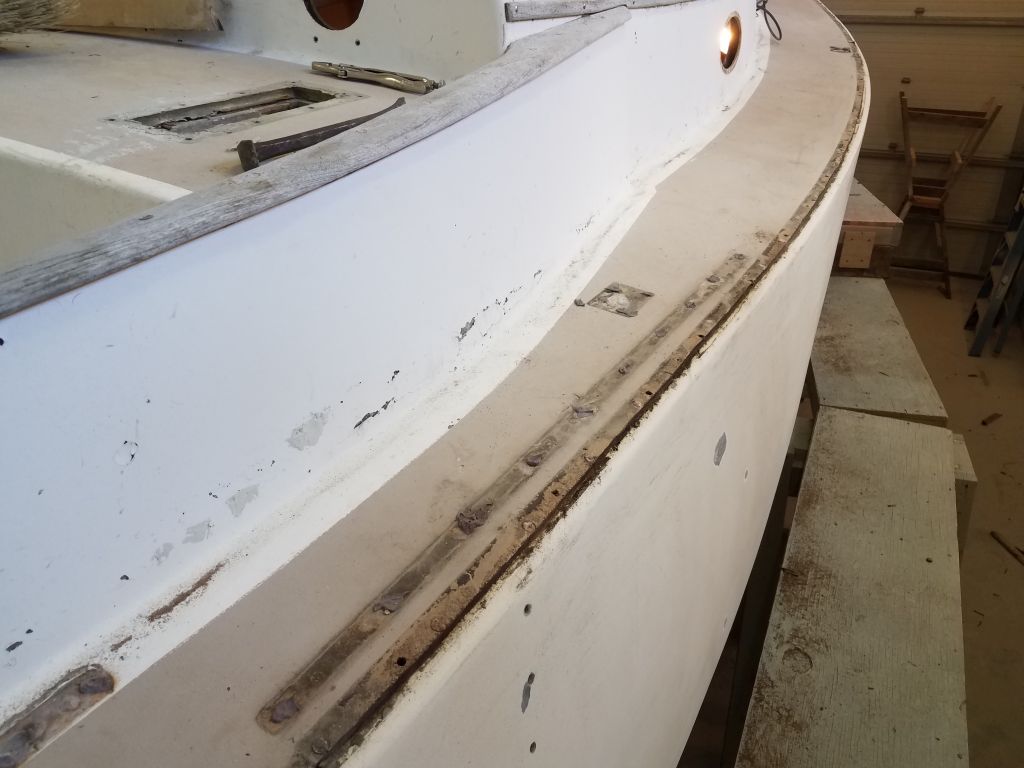
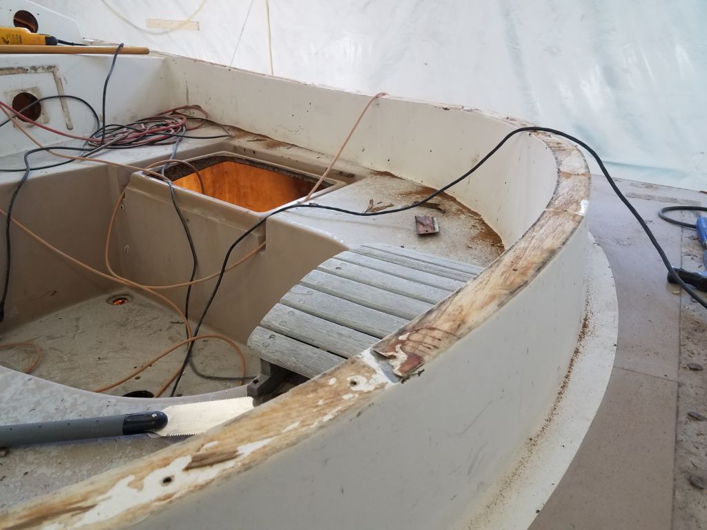
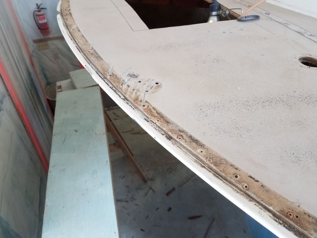
I repeated the process on the starboard side, which appeared to be a completely original installation and featured less silicone than its counterpart to port.
As before, I scraped off the excess silicone from the hull/deck edge.
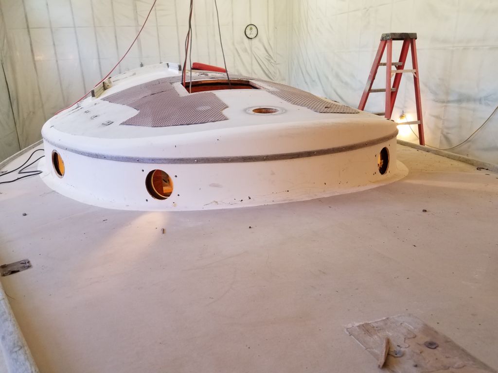
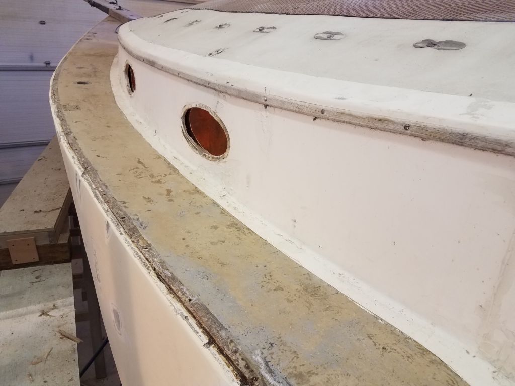
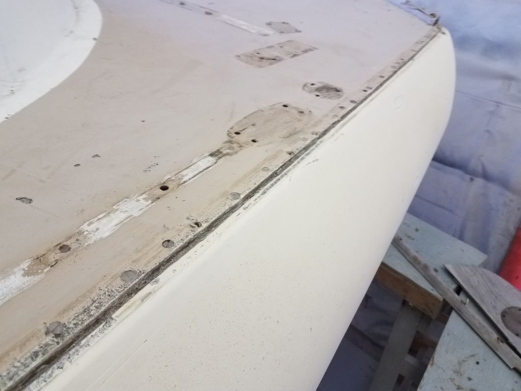
My initial thought was that it would be beneficial to prepare and glass over this hull/deck seam on both sides, to enhance the watertight integrity, reinforce the joint substantially with the need for fewer fasteners, and to open up options for the replacement toerail.
The slim eyebrow trim was secured with exposed screws and came off without any trouble; there didn’t appear to be any sealant beneath the trim. I forgot to get pictures of the port side, but it looked just like this in reverse.
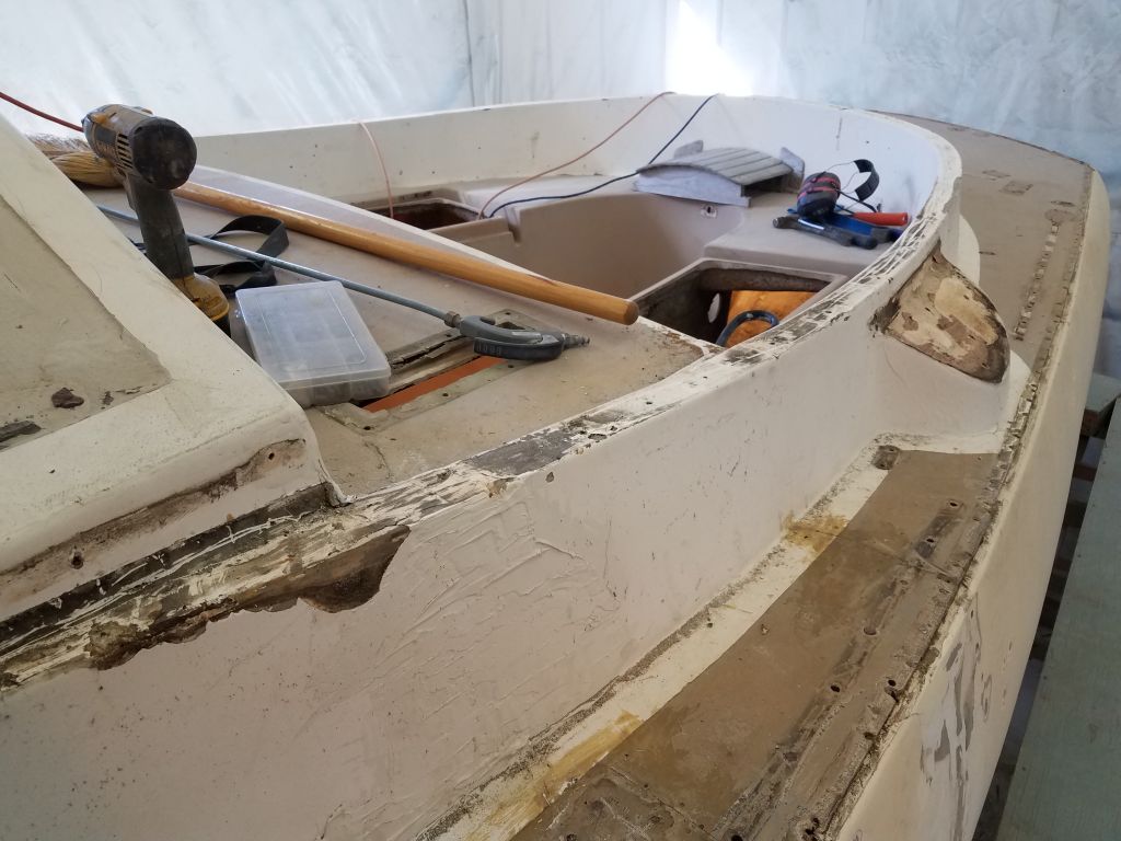
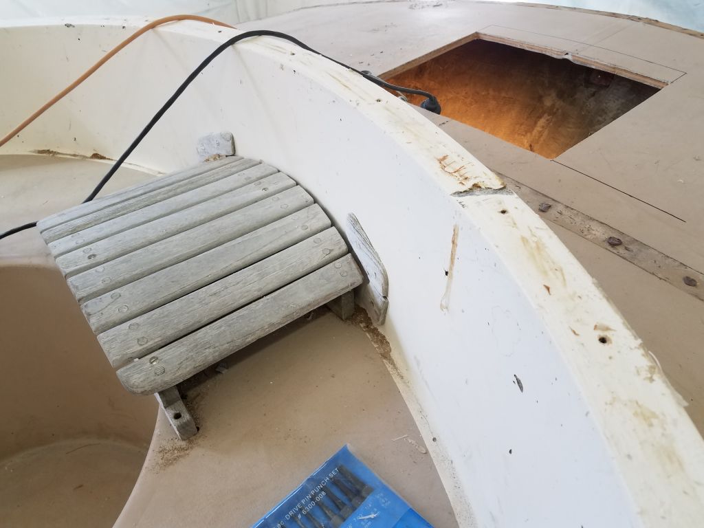
Next, I turned to the cockpit coaming cap, a nicely-shaped and attractive half oval. I’d noticed earlier that portions of this trim were standing proud of the coaming itself, with light visible beneath, and this called into question whether the trim was properly sealed against water ingress. While the trim was also rough and weathered, it might have been salvageable and cleaned up with quite a bit of effort, but earlier the owner and I had decided that it would be best to remove it given the concerns about water. And the wood would probably look increasingly worse as time went on and as the adjacent areas got spruced up. Away!
The original installers on this boat certainly loved their silicone sealant: the trim installations were rife with the horrible stuff, and this little coaming cap might have been the strongest thing I’d tried to remove so far, given the rubbery resistance silicone offers to clean removal. I call this sort of installation the Inverse Structure Theory, something I’d often seen on older boats where the silliest things seem the most sturdily installed while seemingly important structures can be haphazard at best. Never mind tabbing the bulkheads–but make sure that 2″ coaming cap can be used to lift the whole boat even if the fasteners fail.
In any event, I removed the cap, at times with difficulty, and scraped away the jiggly 3/16″ thick layer of silicone from the top of the fiberglass coaming with even more difficulty.
Finally, I removed the taffrail, which was uneventful. I cleaned up the day’s detritus, along with the bulk of the sanding dust on the floor from the hull, and got ready for a thorough deck and core inspection next time.
Total time billed on this job today: 5.25 hours
0600 Weather Observation: 22°, clear. Forecast for the day: Sunny, low 30s
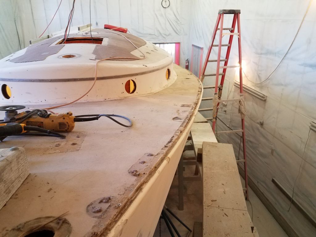
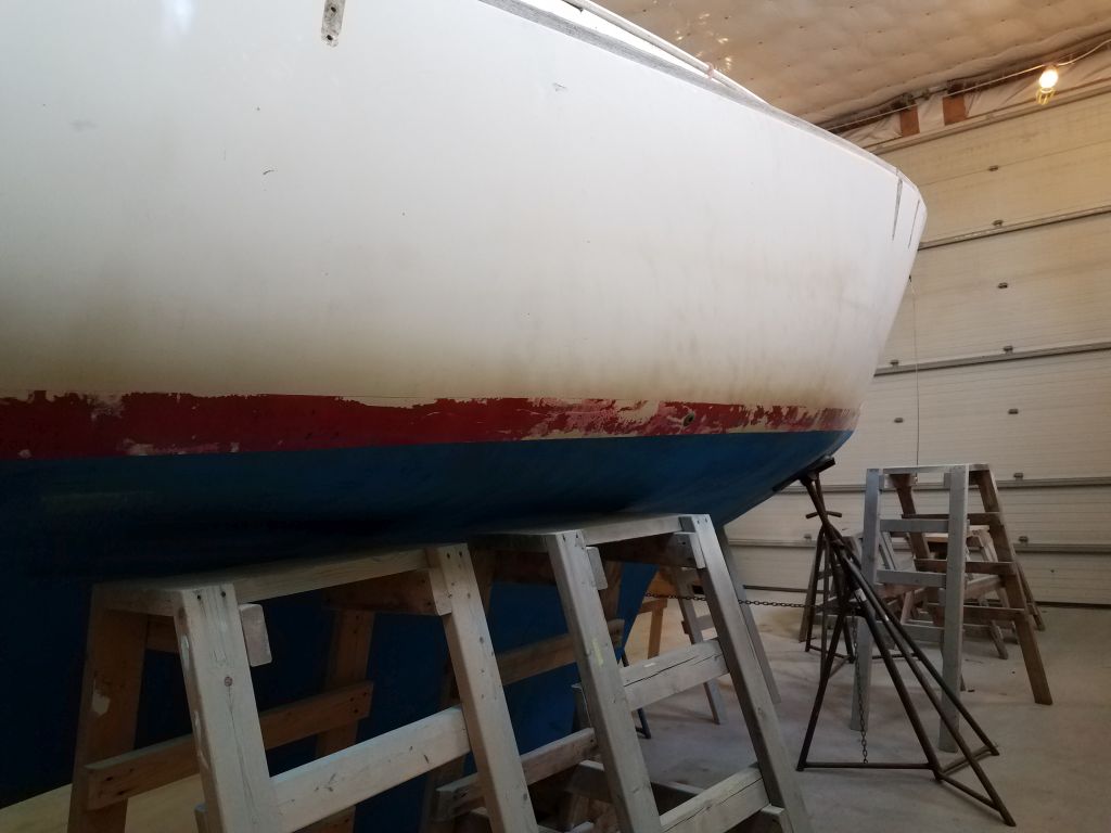
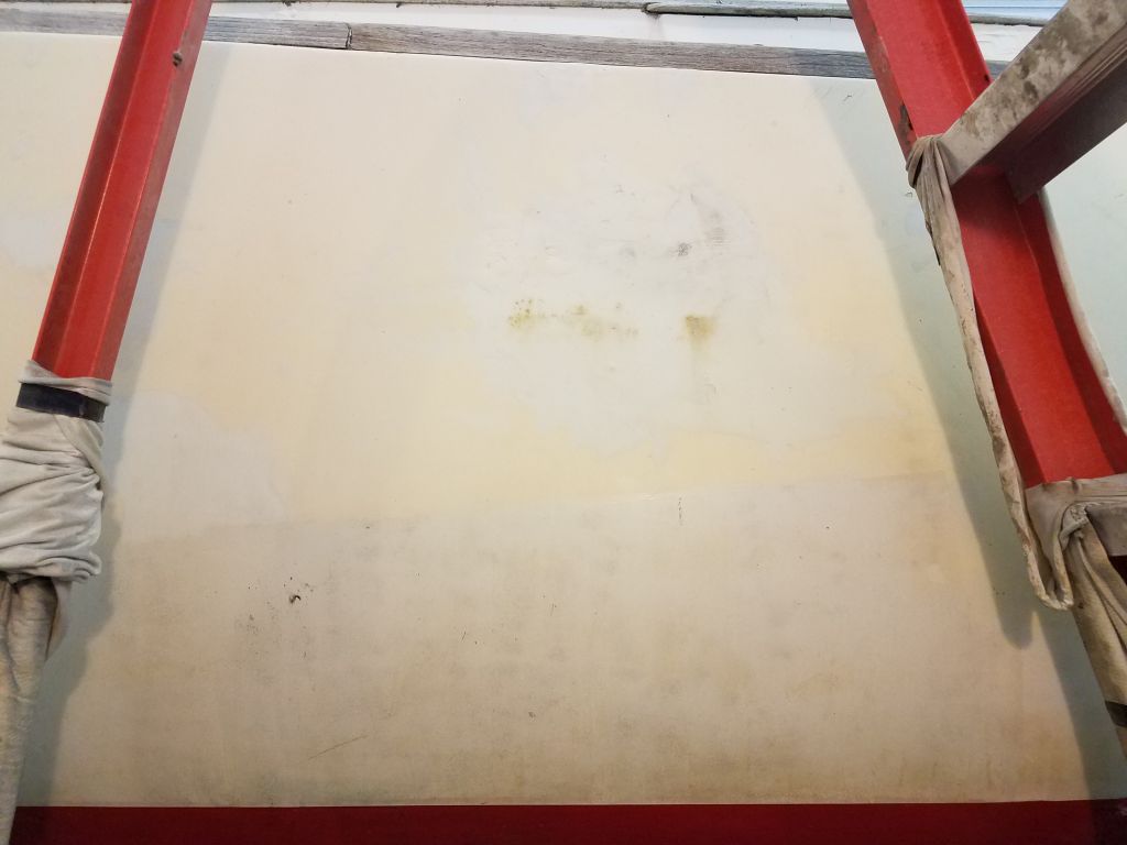
To continue sanding the hull, I set up staging to allow me to reach all the way to the gunwale.
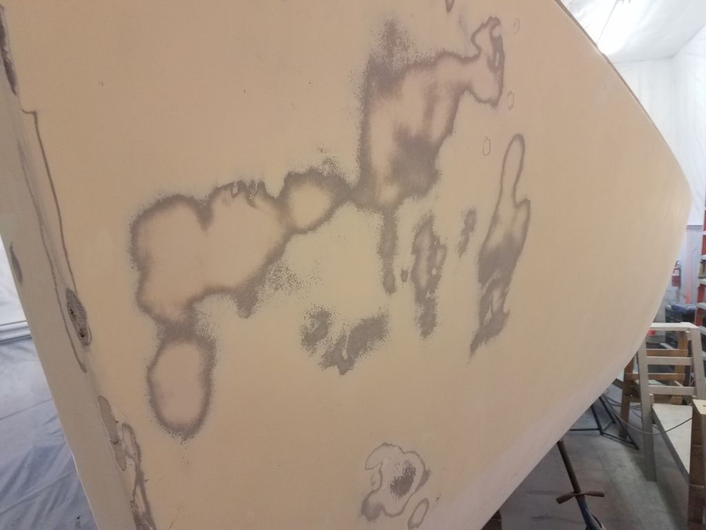
I worked my way along both sides of the boat, sanding the existing surface with 80 and 120 grits on my 6″ finishing sander to scuff and prepare the substrate for additional work as needed. The starboard side was in much better condition than the port side, but in both cases the basic sanding was straightforward. On the port side, I sanded the various repairs to begin to smooth them, but it was clear most of the messy work would need additional attention to remove suspect fairing compound, thickened gelcoat, and what have you.
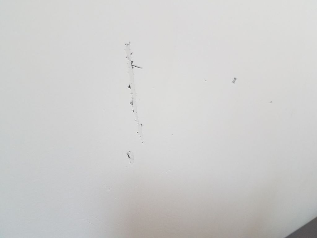
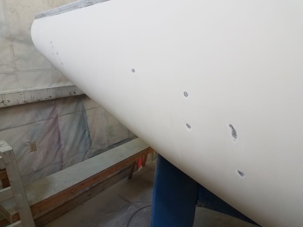
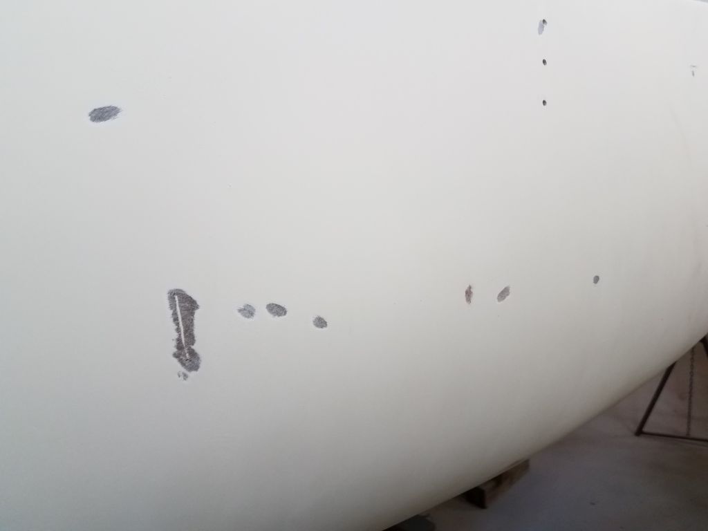
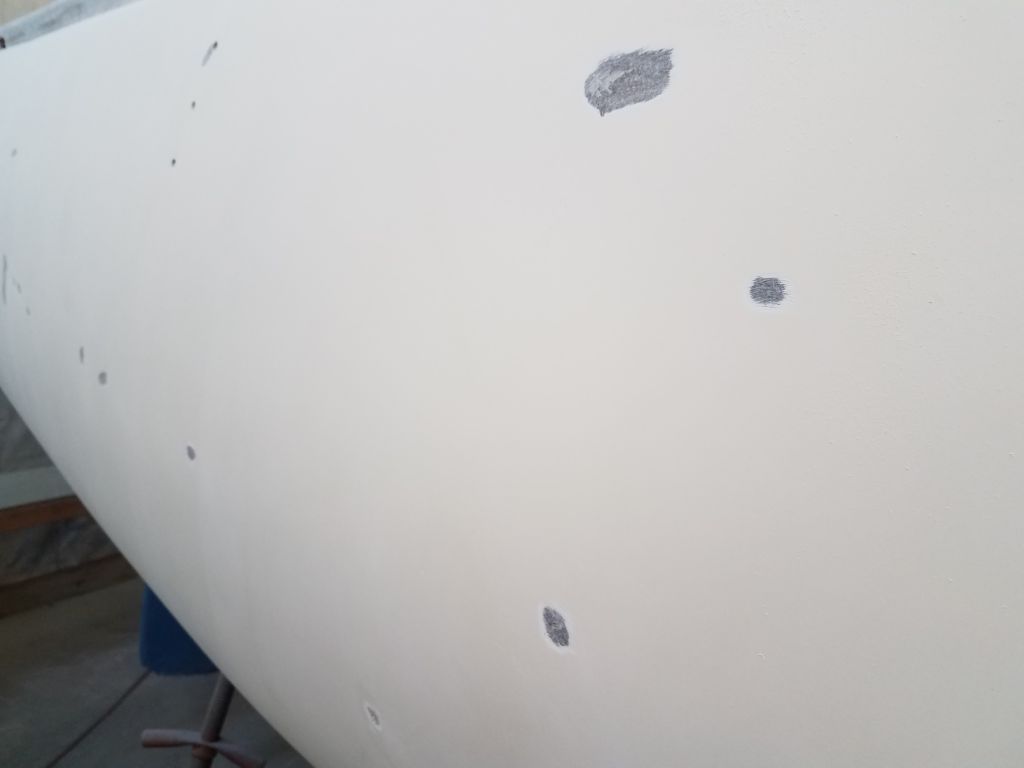
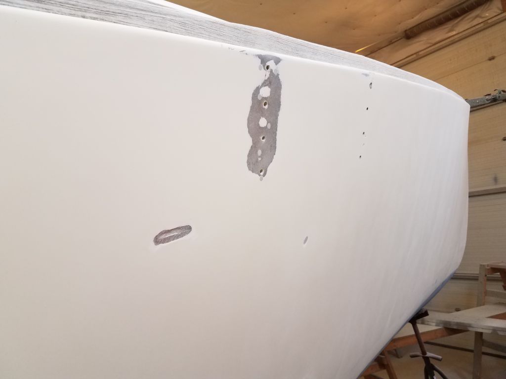
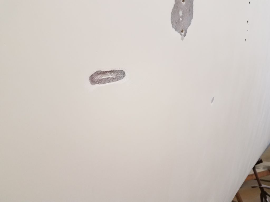
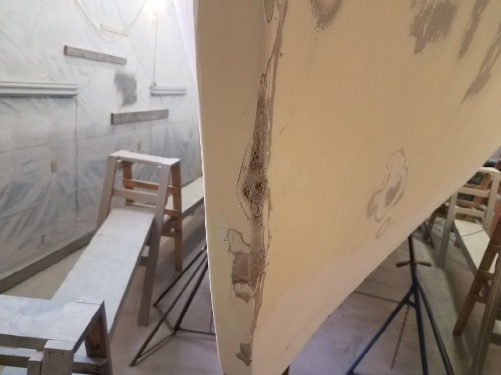
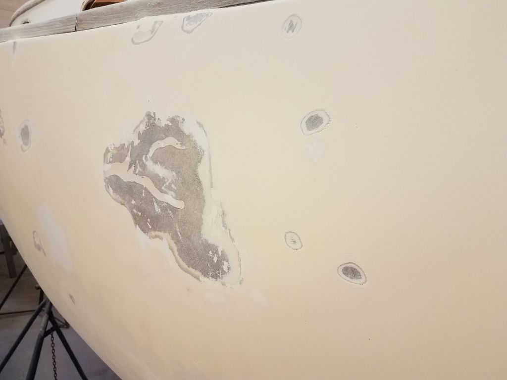
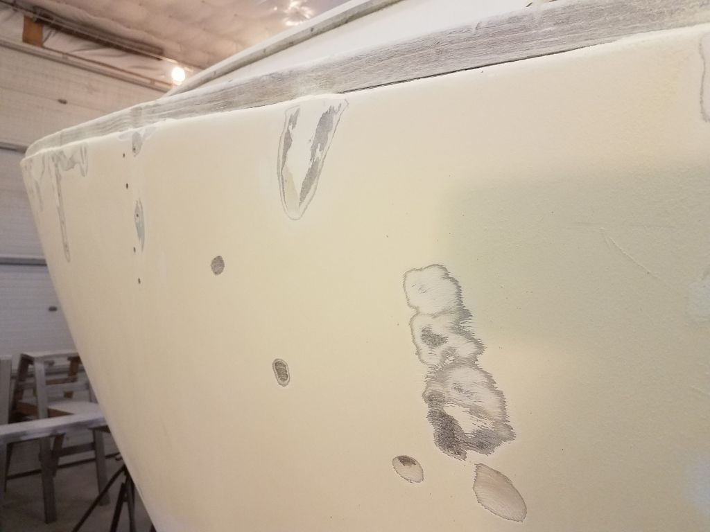
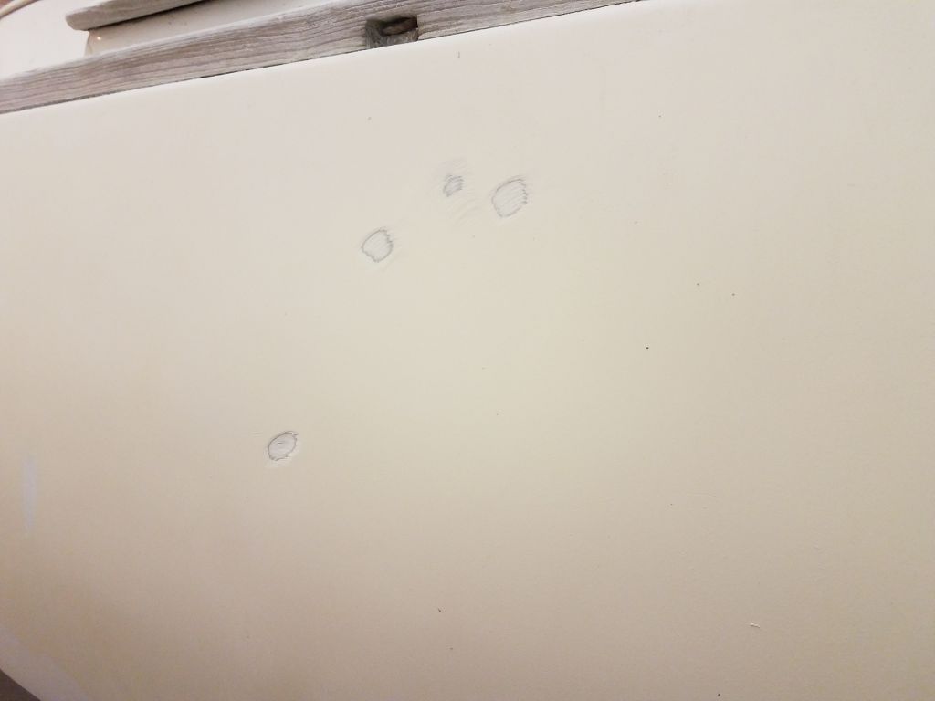
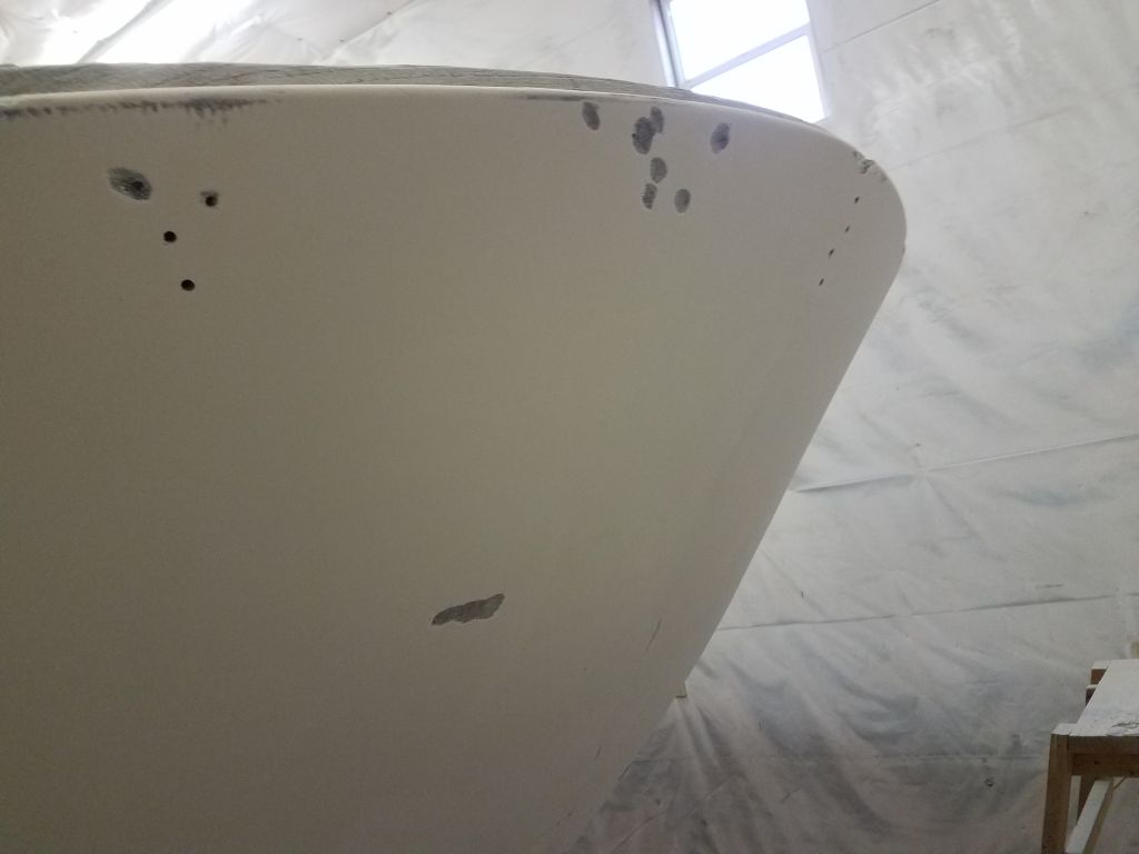
With the initial sanding rounds complete, I went around the boat closely with a small sanding disc to gouge out small dings, gouges, gelcoat pinholes, and so forth. The starboard side had the usual collection of these areas, and I used the small grinder to broaden the areas and provide a wider area to accept fairing compound later.
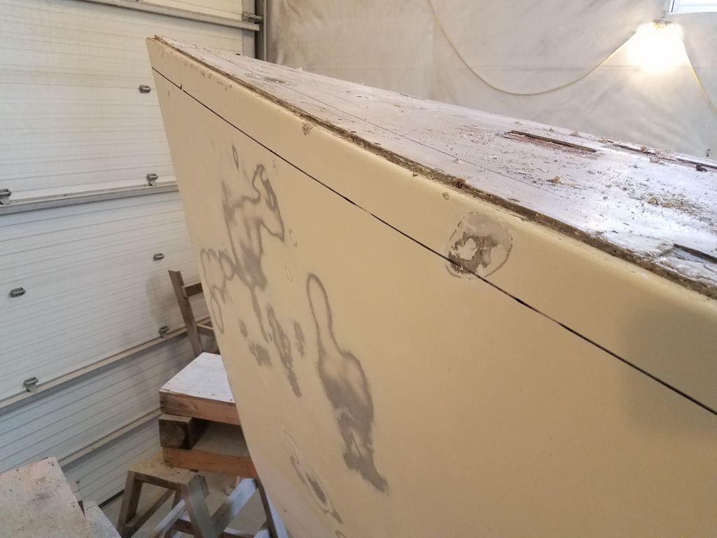
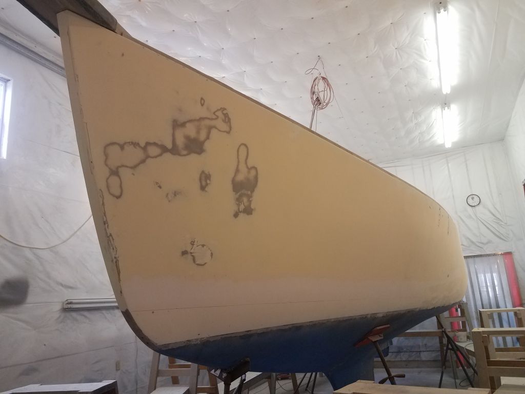
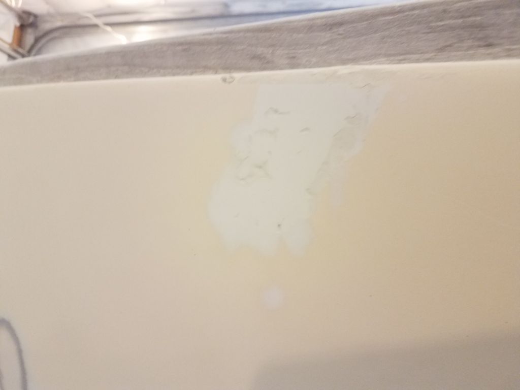
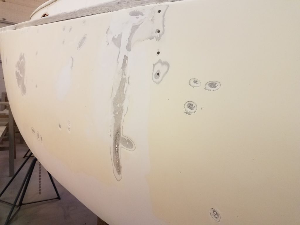
On the port side, I did the same thing, but here I also concentrated on all those visible repairs, many of which I felt needed to be ground down so I could refair the areas more appropriately. It seemed that the port side had been painted before too (not the starboard, though), and there was some minor paint adhesion failure at the port bow that I sanded away. This was the first real indication I’d had that there might be paint on the hull, as the overall color and appearance had been close to that of the starboard side, other than the obvious damage on the port. I hoped not to have to remove all the paint, but for now I reserved judgement pending further inspection and additional work. Only the bow showed signs of any adhesion failure.
The hull looked a mess when I was done, but it also looked like progress, a better situation than the sorry appearance of the multiple patches and colors before.
The main focus of the work ahead would be on deck, and I wanted to keep moving on the major demolition, sanding, grinding, and repair work, so with the hull prepared for its relatively minor level of work, I went ahead and reset the staging to deck height, where I planned to spend the next several weeks on the numerous repairs and substantial surface prep required. I had to add a second layer of staging at the forward end to allow comfortable working height at the bow, wits its substantial sheerline.
Total time billed on this job today: 6.5 hours
0600 Weather Observation: 34°, rain. Forecast for the day: Showers and clouds, around 40°
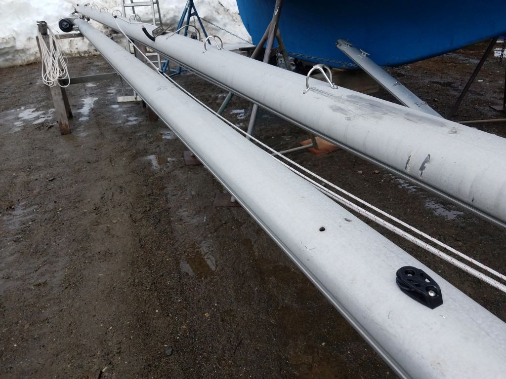
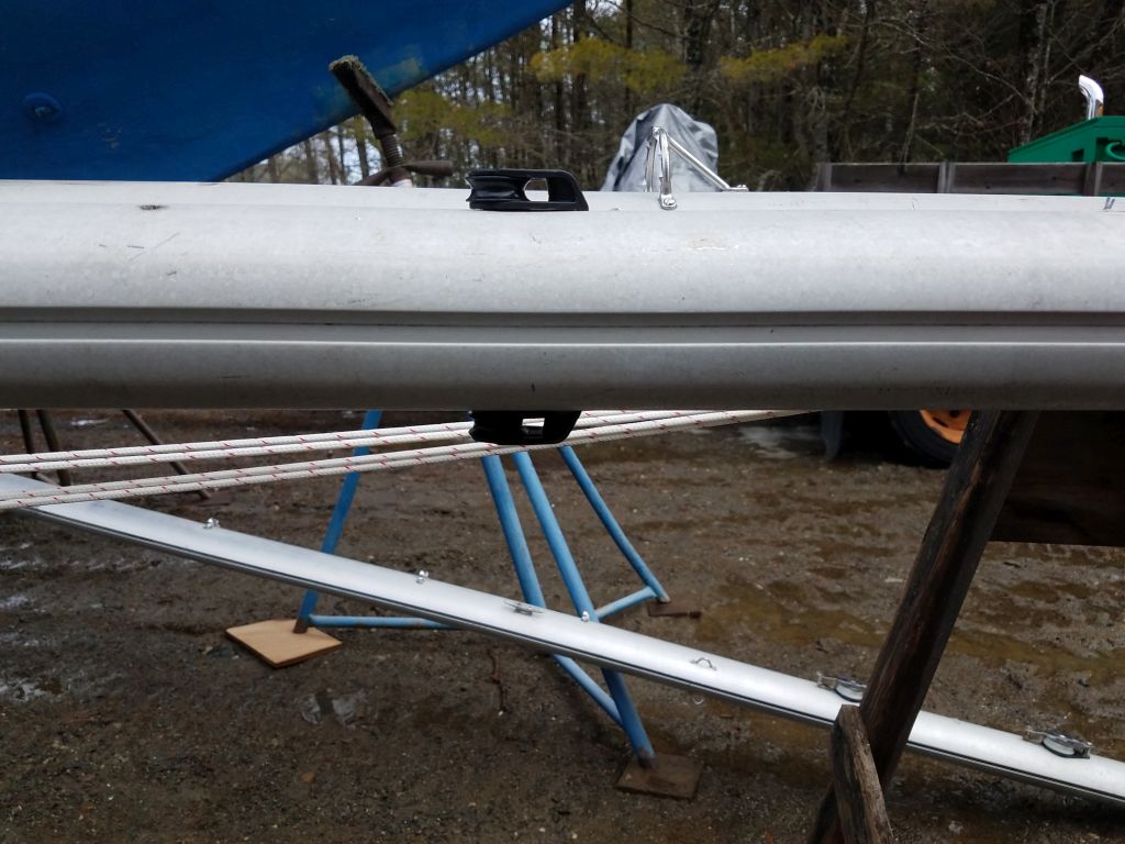
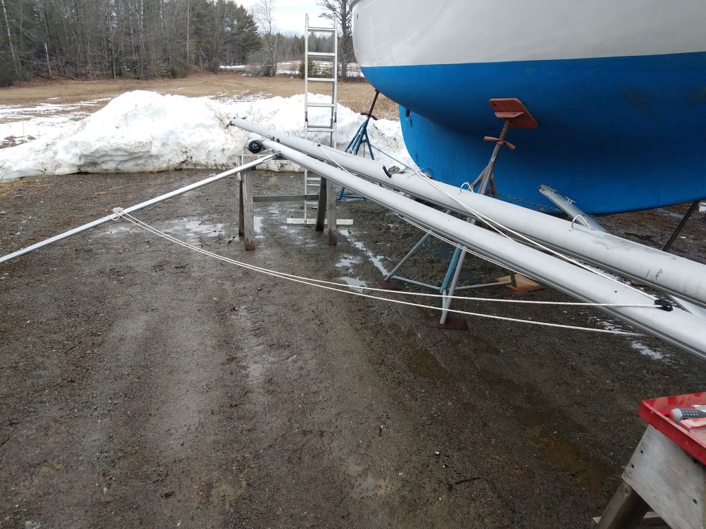
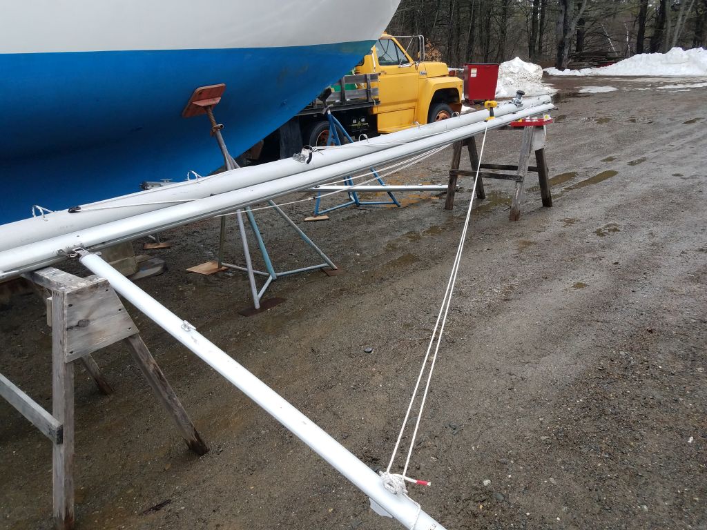
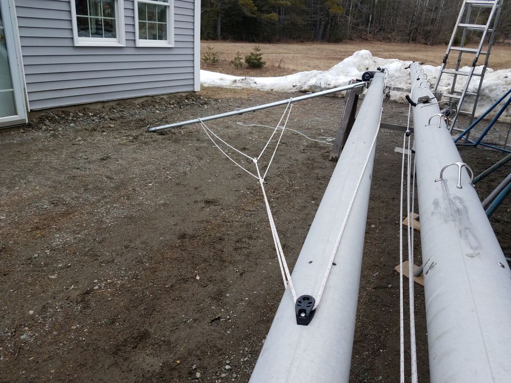
On the mizzen mast, I repeated the same basic installation process for the lazy jacks, starting with cheek blocks mounted a couple feet below the sidestay tangs.
My original thought had been that a single leg would be sufficient for the mizzen, which I’d imagined was a little smaller. But when I strung the line and looked at the boom and mast in reality, I thought that the single leg might not be sufficient after all, as the boom was a bit longer than I’d pictured in my mind while planning, so I decided to go with two legs on each side like on the main mast.
After a delay while I awaited new parts to come so I could finish the modified mizzen jacks, I finished up the installation with extra blocks, additional line, and eye straps on the boom, stringing the lines as with the main boom to create a pair of adjustable legs on each side and allow for retraction of the lazy jacks when desired.
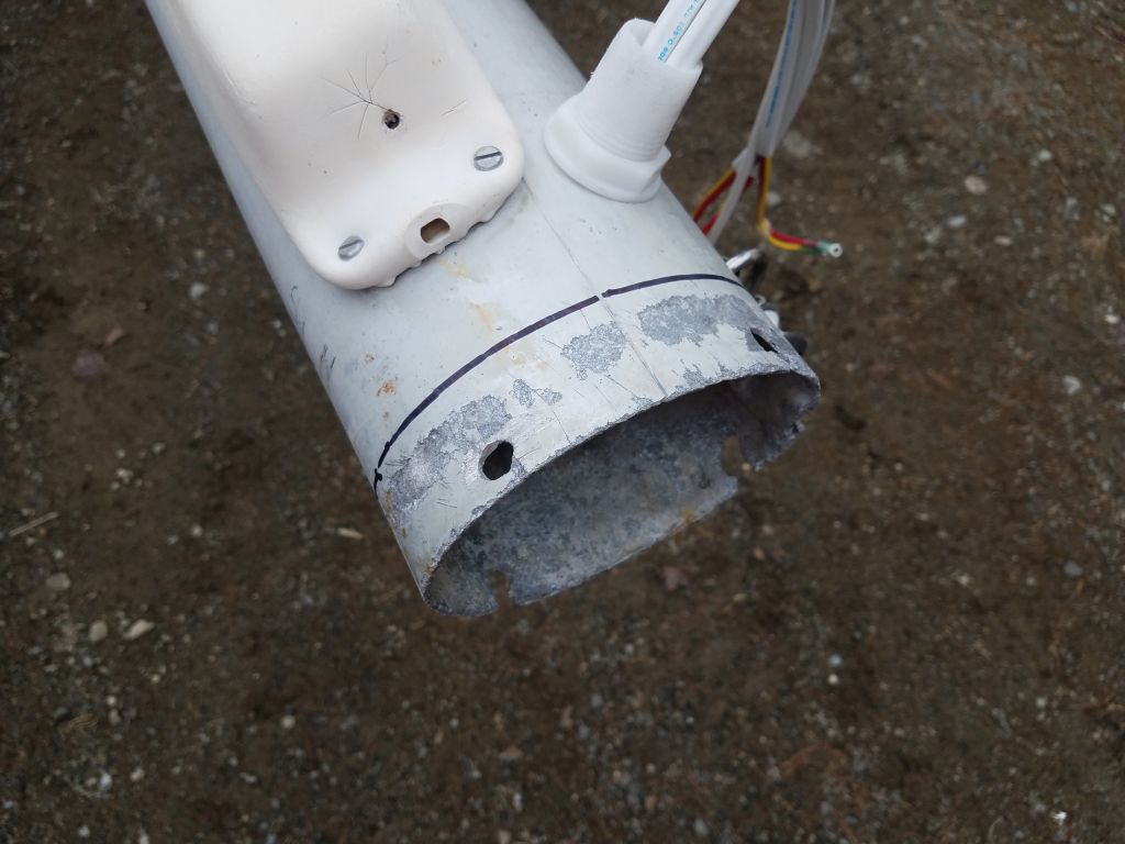
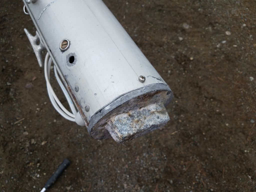
The final task for me on the mast was to remove the corroded part of the mast butt. I’d originally planned on having the riggers do this along with their work list, but with some time on hand now I decided to take care of it. Earlier, I’d determined that I needed to remove 1-1/2″ of the mast to clear the old corrosion at the bottom, and I’d rebuilt the mast step on the boat 1-1/2″ higher to accommodate this. To begin, I made a mark at the correct height all around the base of the mast. Then, I cut to the mark with a saw.
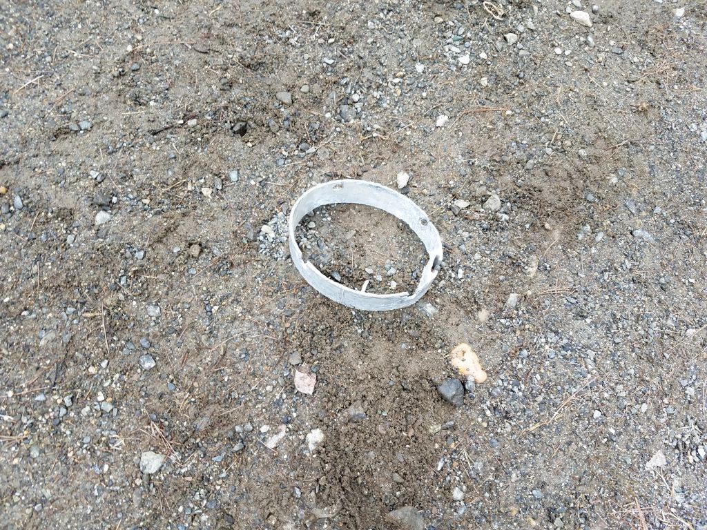
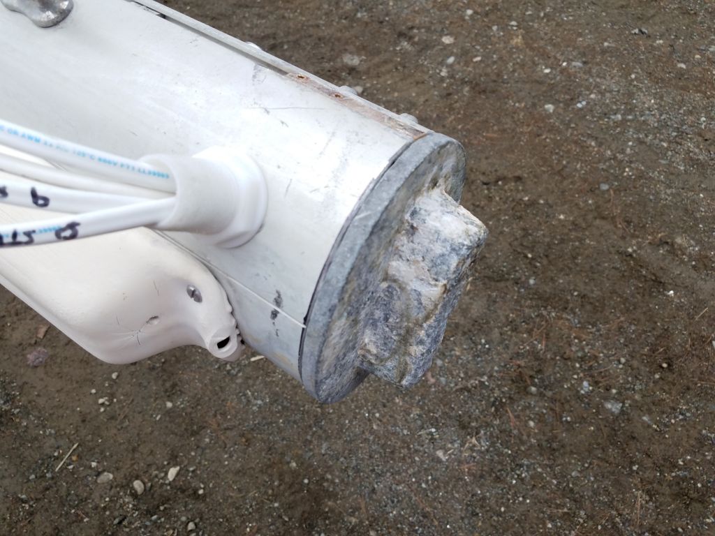
After some minor work to accommodate the cast aluminum mast base plug, I finished up by reinstalling it with a couple machine screws to hold it in place; I didn’t see why it needed any more than two.
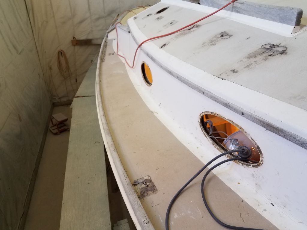
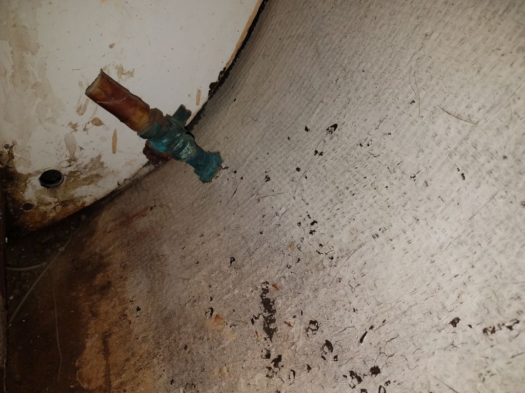
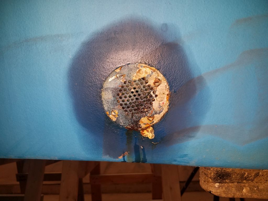
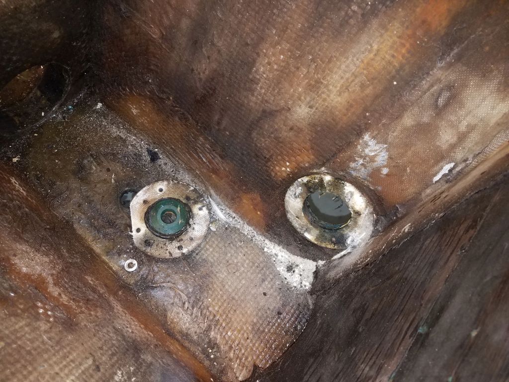
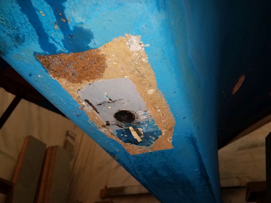
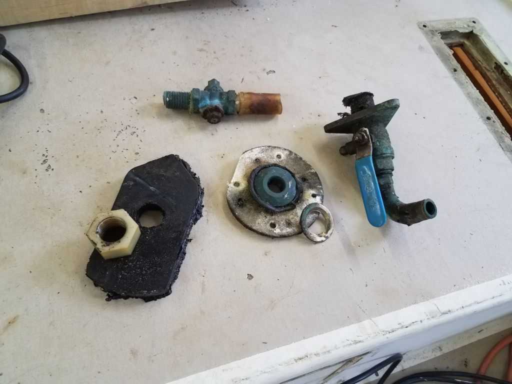
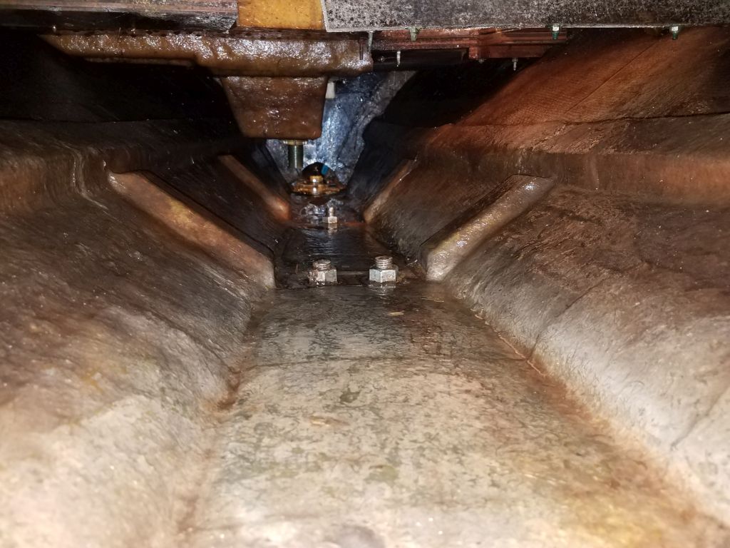
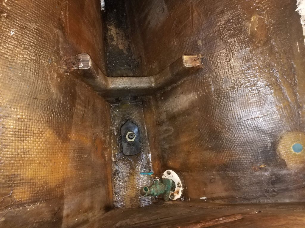
Now that I’d completed the bilge soak, I could remove the final through hull fittings from the boat: a transducer in the very bottom of the boat beneath the (former) engine, and the old engine intake through hull and valve. There was also a small sink drain fitting near the head sink that I’d not gotten around to before.
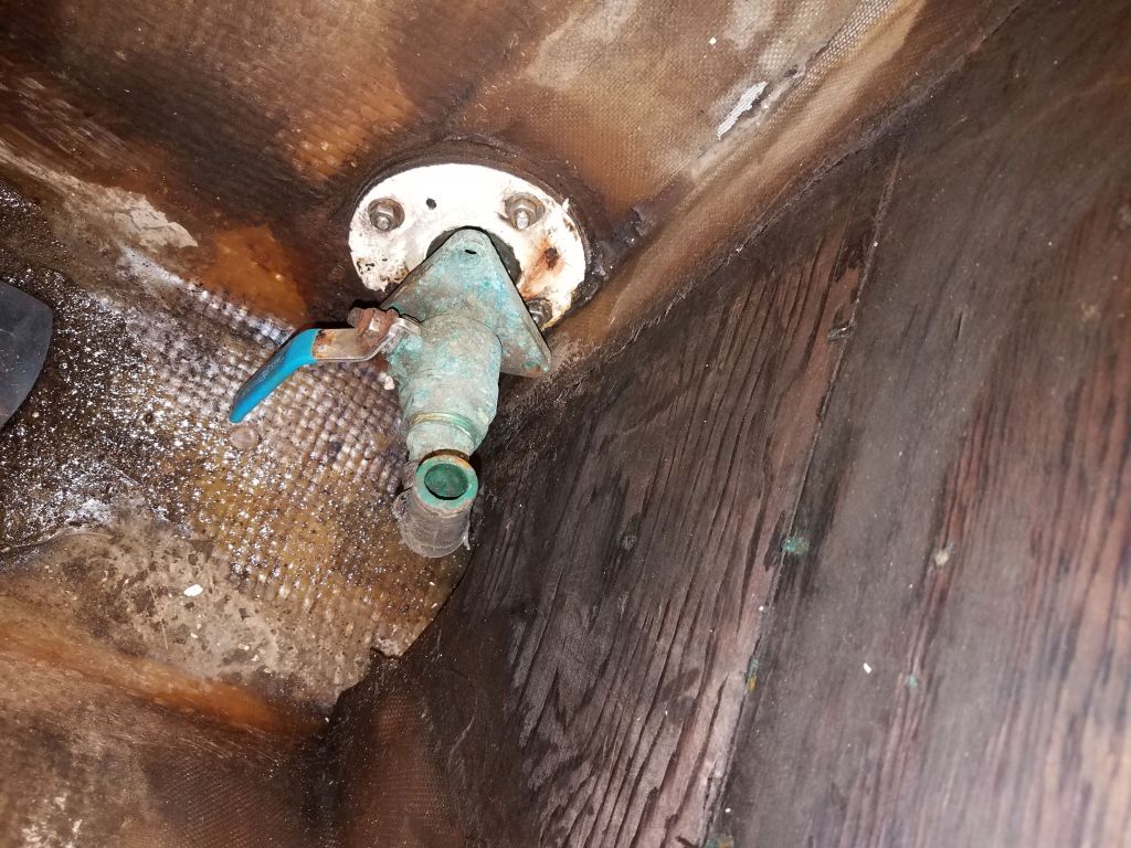
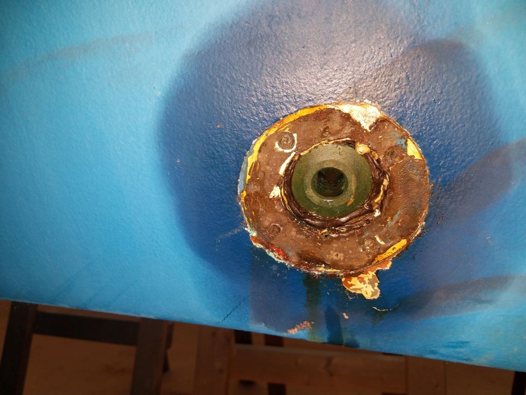
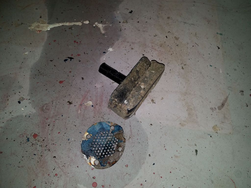
The engine intake fitting was a convoluted arrangement that turned out to be nothing like I’d expected. Seeing four nuts on the inside of the backing plate, and four screws on the outside of the flush screen fitting, I’d logically assumed one begat the other, so after cutting off the valve inside, I removed the nuts and tried to bang out the bolts to no avail. I figured they must be in tapped holes, so from outside I removed the screws and then the screen fitting, revealing a normal through hull set inside a recess–a recess created by the strange two-layer backing plate within. Back inside the boat, though, I found that the threaded parts of the bolts were still there–obviously another set of four bolts. Eventually I removed those and the second layer of backing plate, along with the mushroom head of the through hull, completing the removal. The huge transducer fitting came off with little effort.
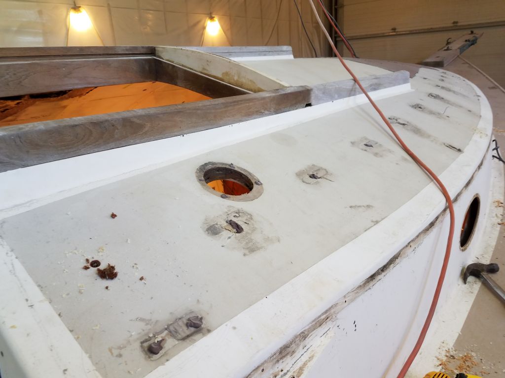
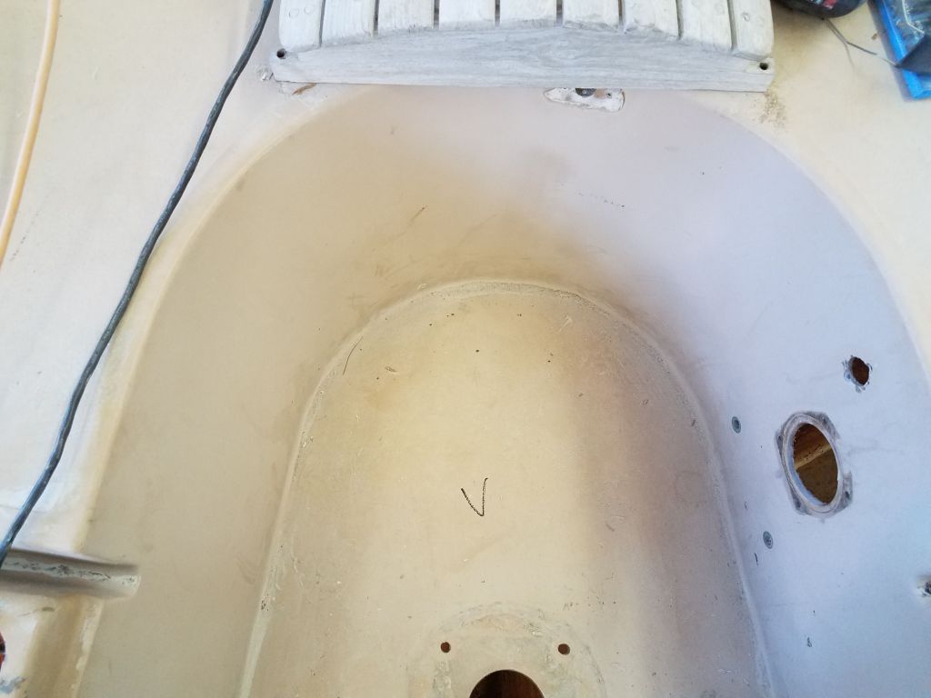
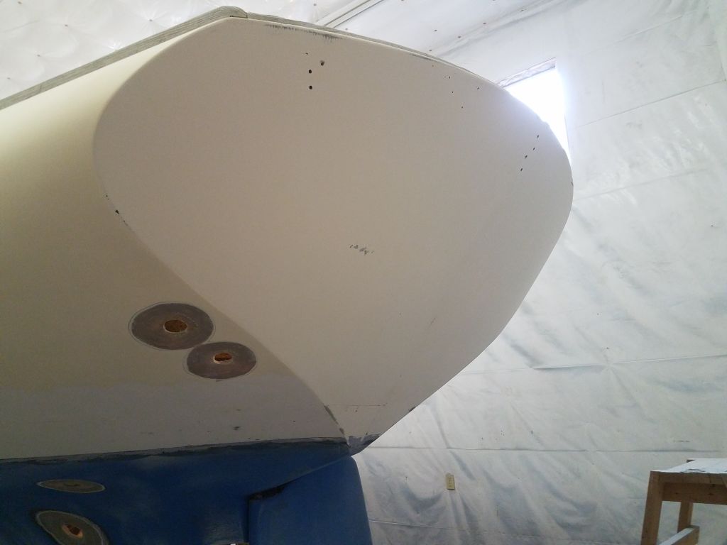
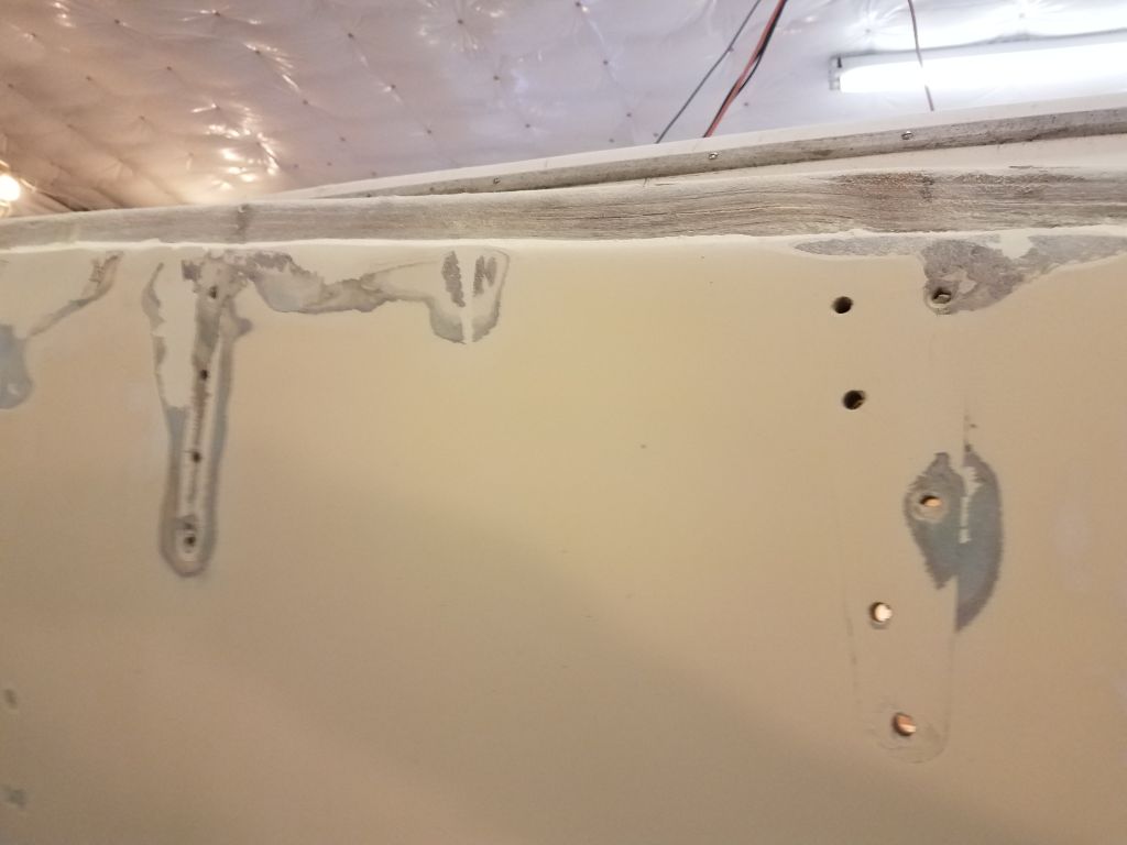
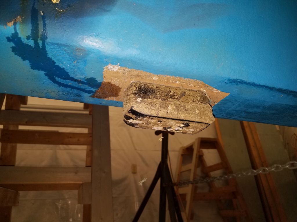
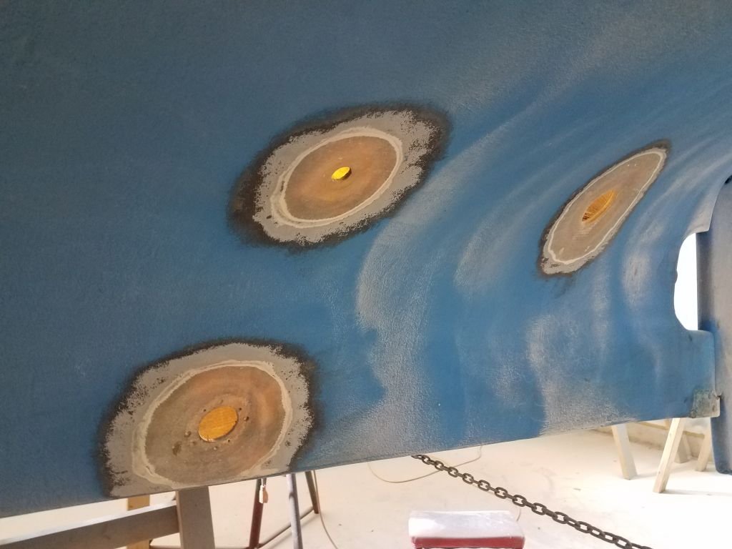
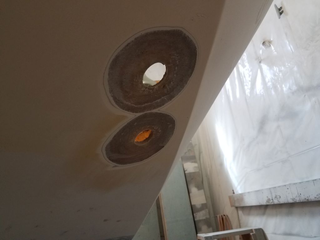
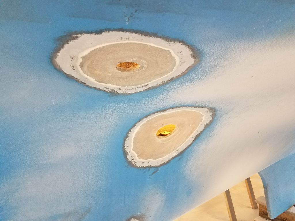
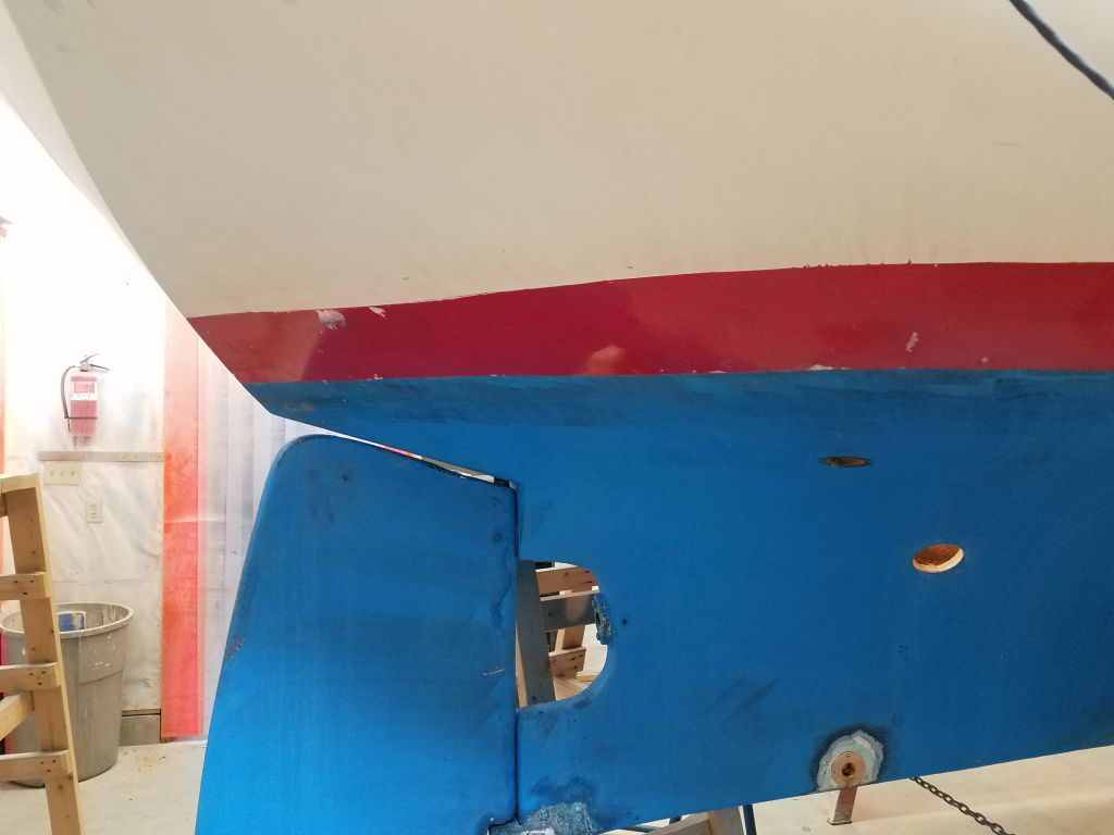
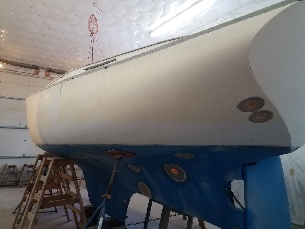
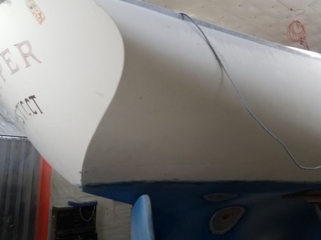
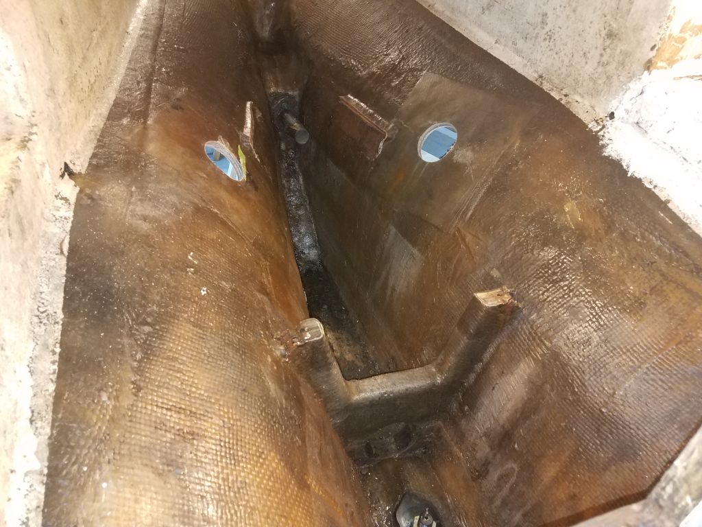
With all the through hulls now removed, I used a grinder to prepare the hull around each location for repairs and patching, creating tapered dish-shaped recesses concentric with the old through hull holes for all 9 underwater fittings (including that skeg-mounted transducer, which I forgot to photograph here), plus three others at or above the waterline. Patching would come a bit later in the process.
The bottom was in good outward condition with only a layer or two of bottom paint. Also, my work now, as well as earlier at the garboard, had revealed the existence of what appeared to be a barrier coat (gray), which tied in with the generally good condition of the bottom paint and lack of the heavy buildup one would expect on an older boat. This was good news to me, as it all meant there was no immediate reason to strip the bottom and start over.
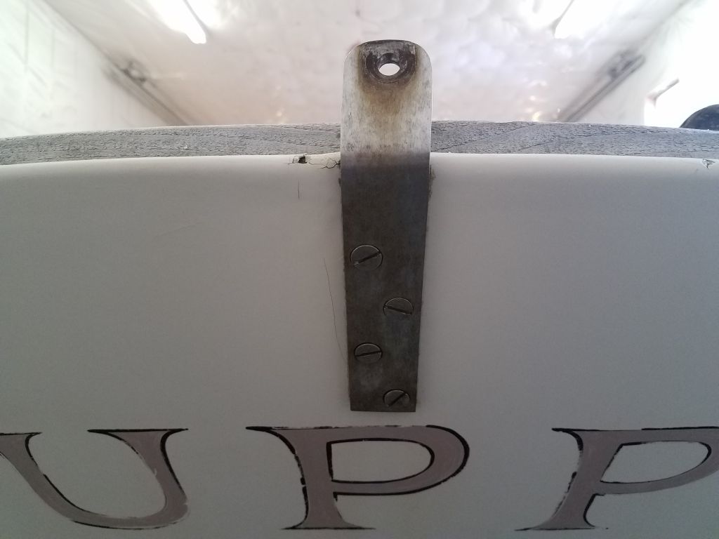
With good access now through the new poop deck hatch opening, I removed the backstay chainplate from the center of the transom.
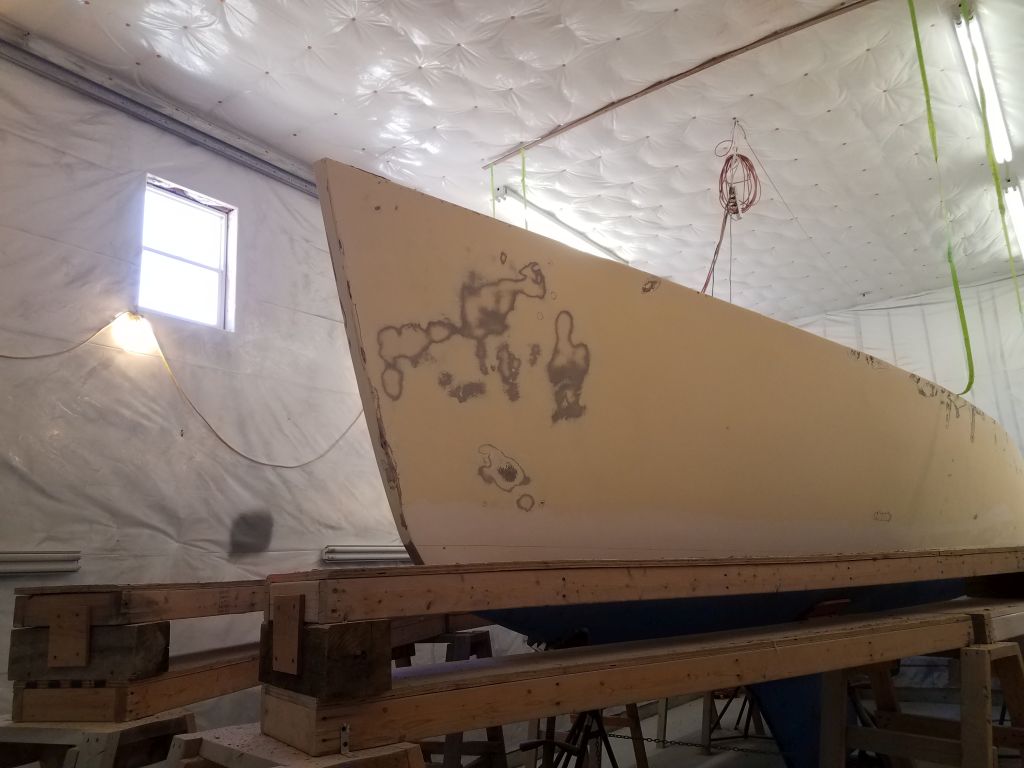
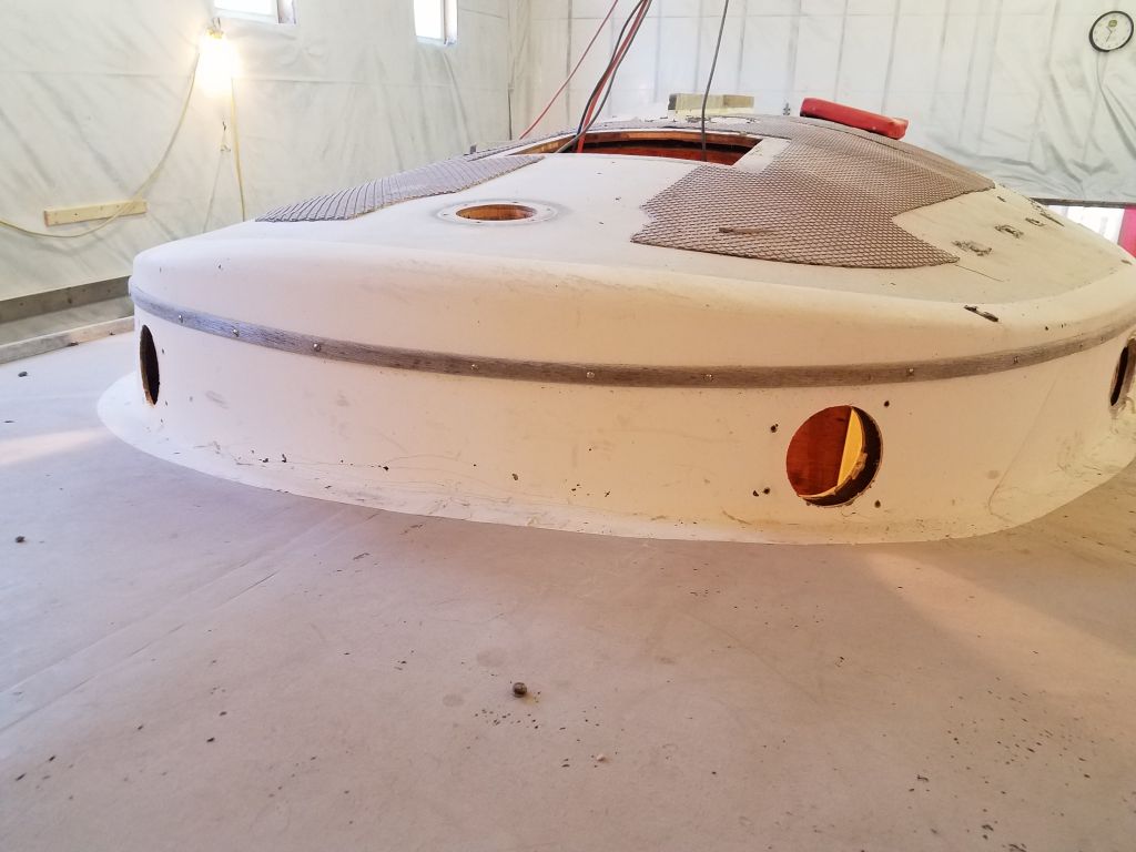
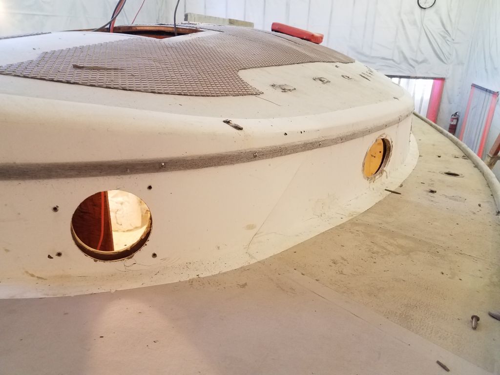
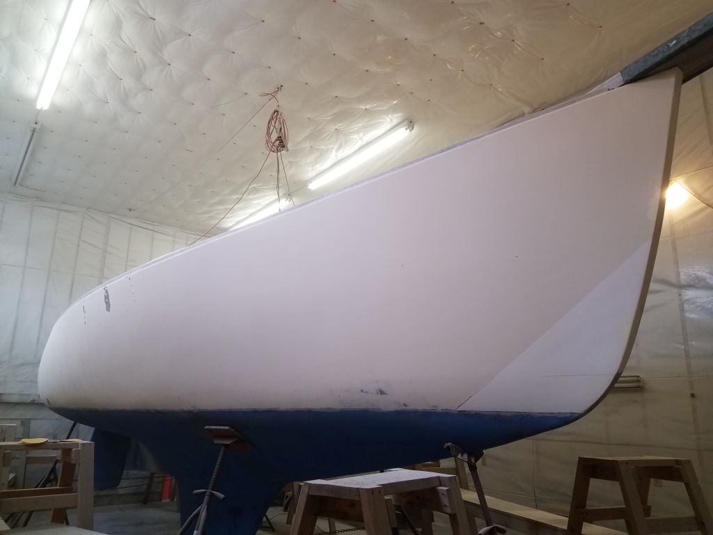
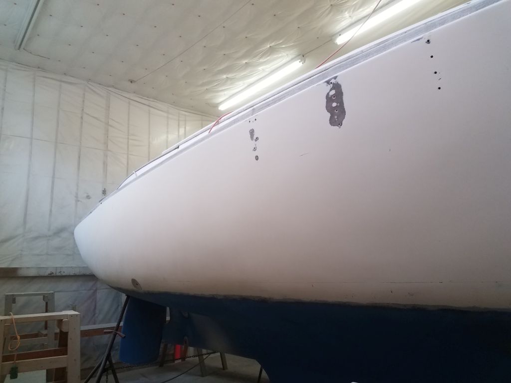
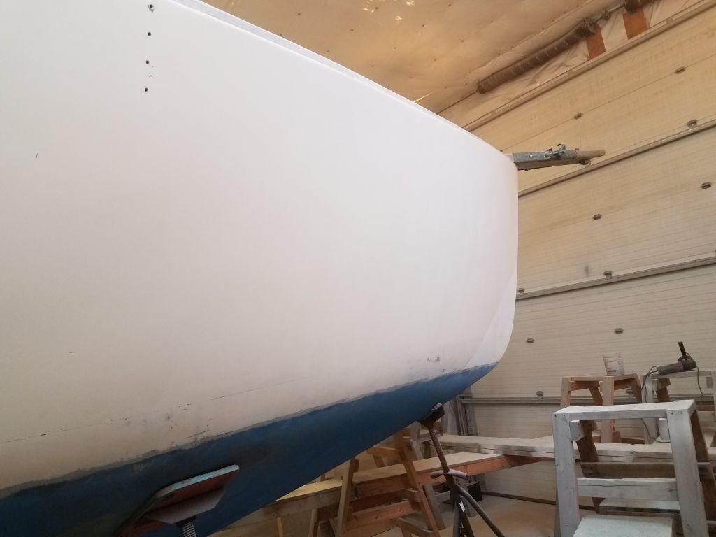
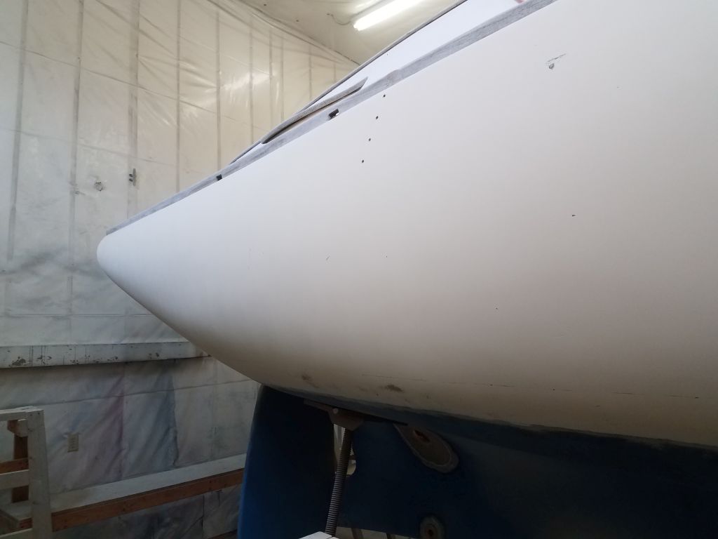
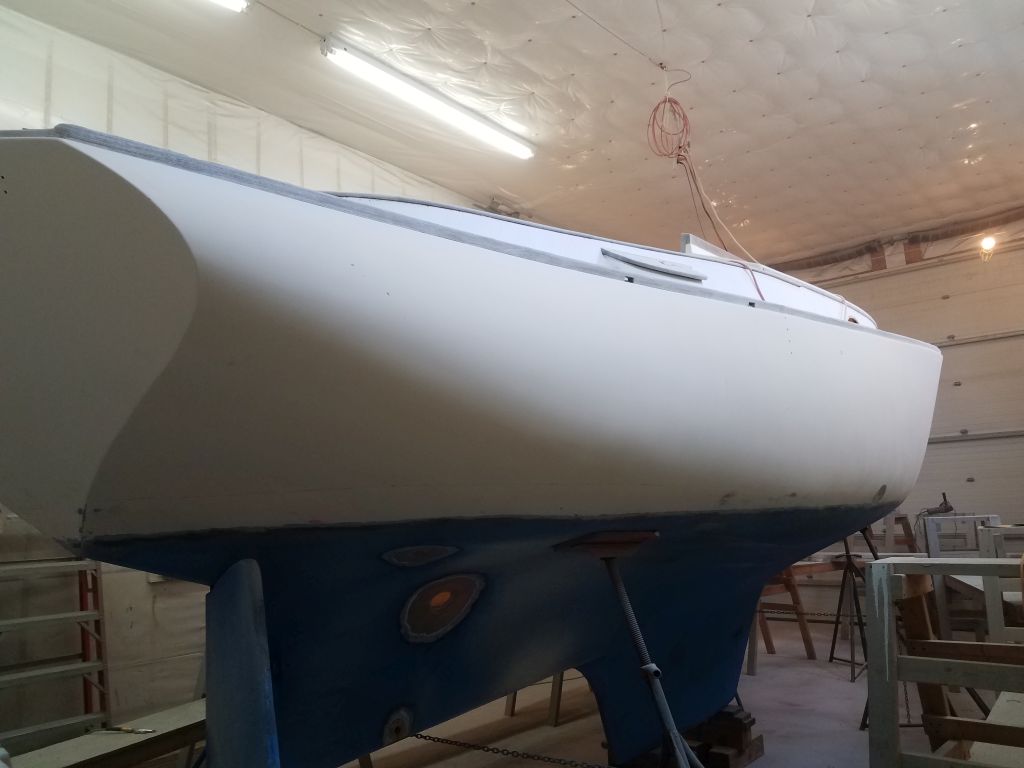
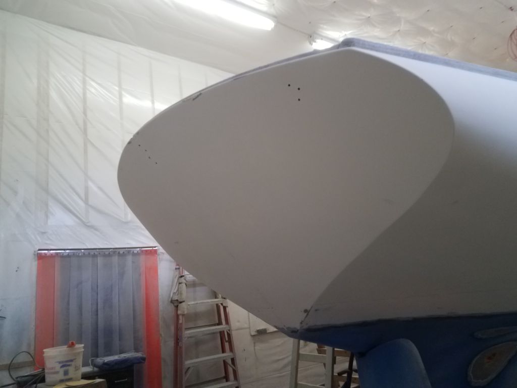
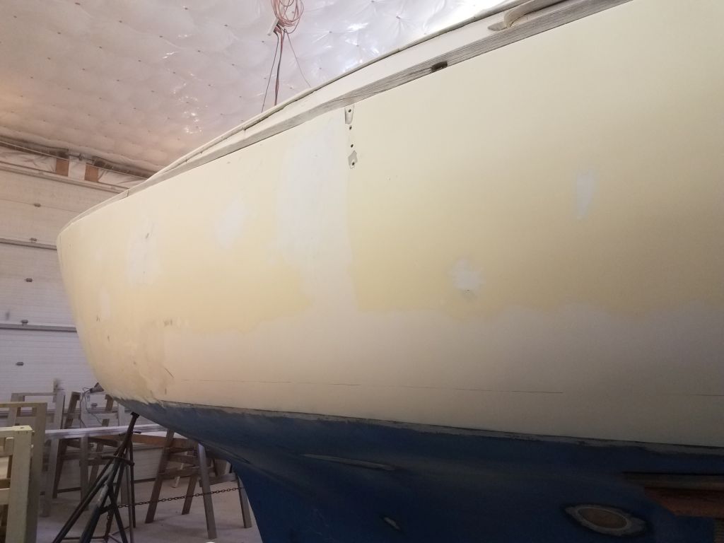
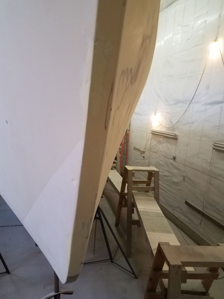
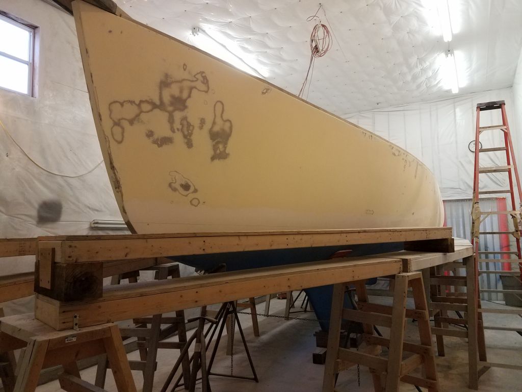
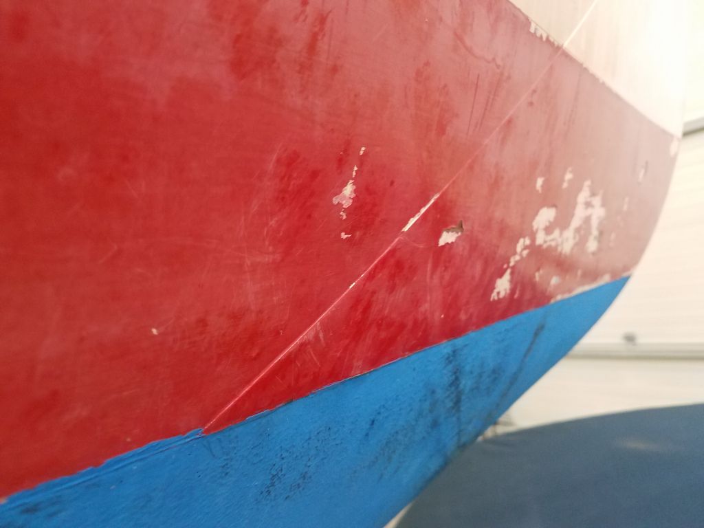
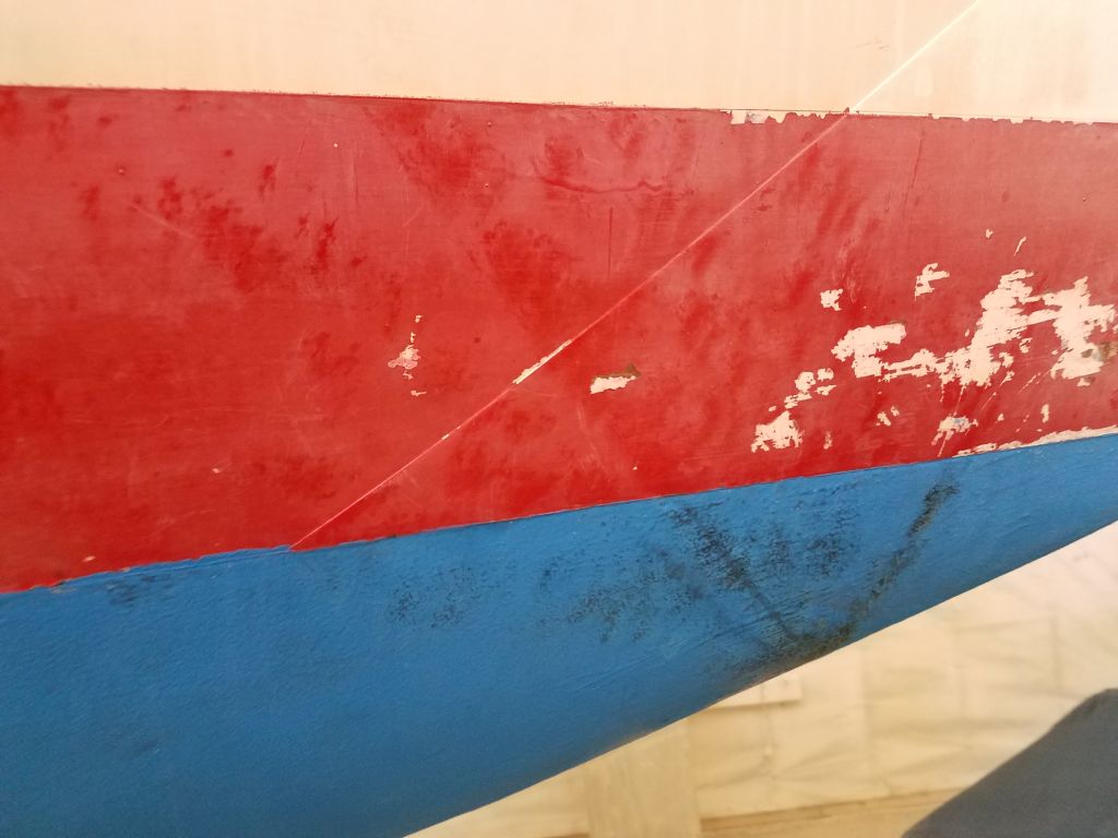
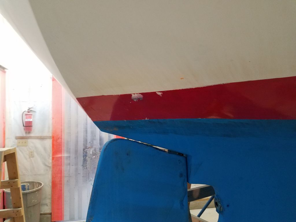
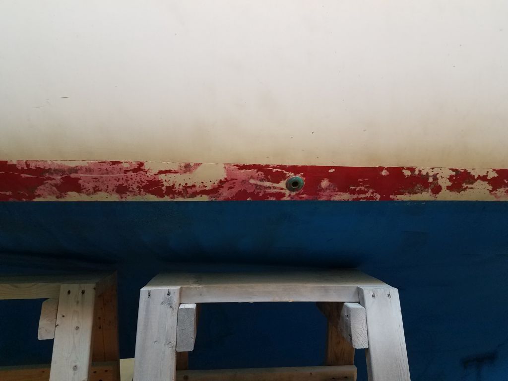
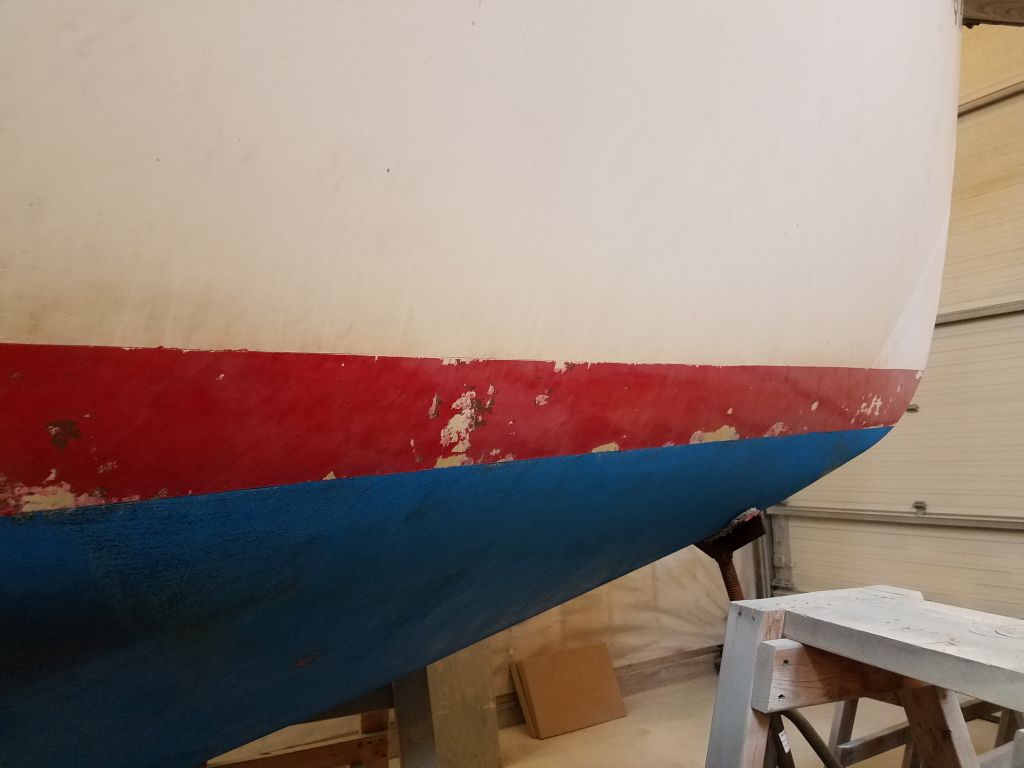
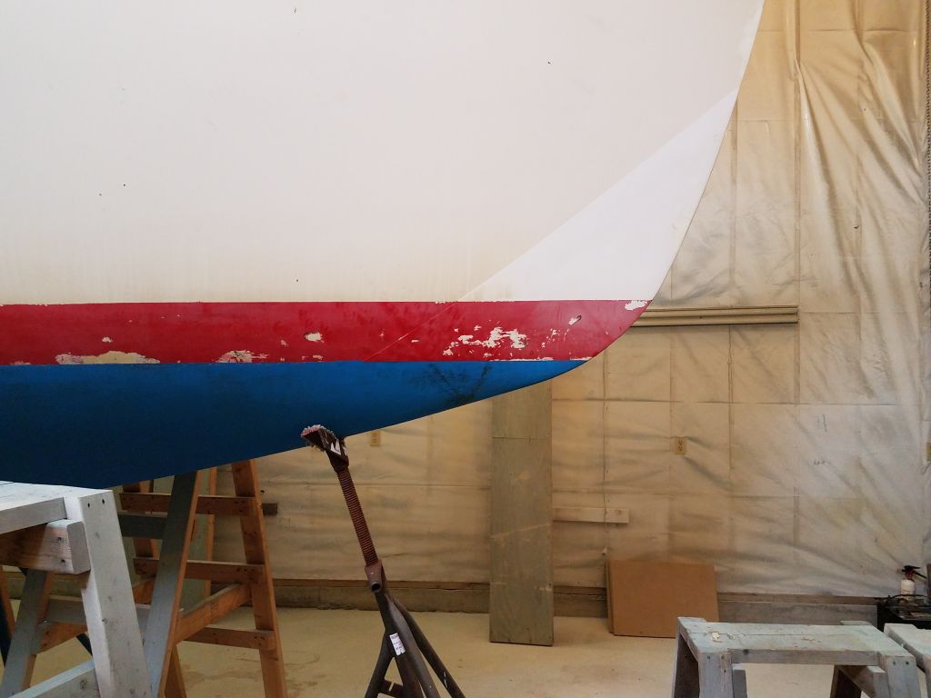
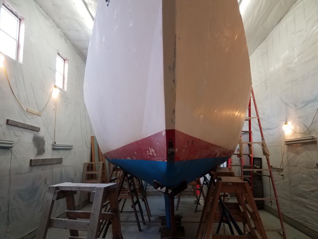
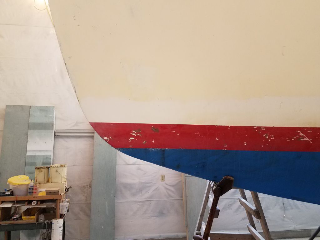
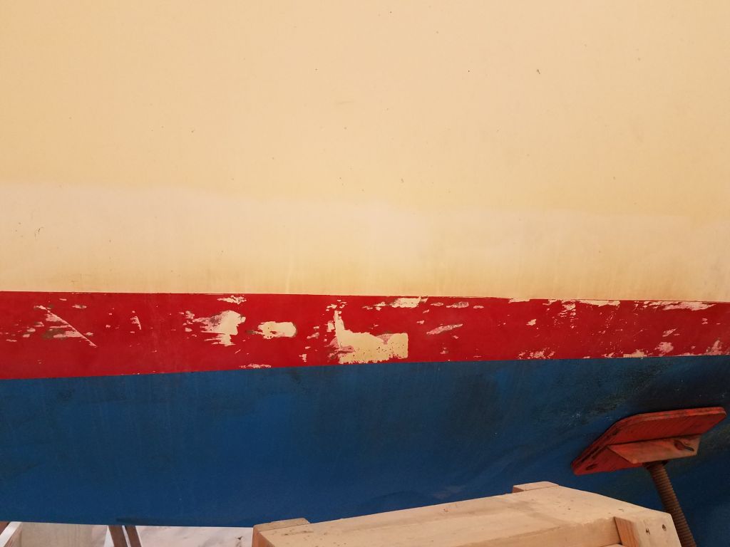
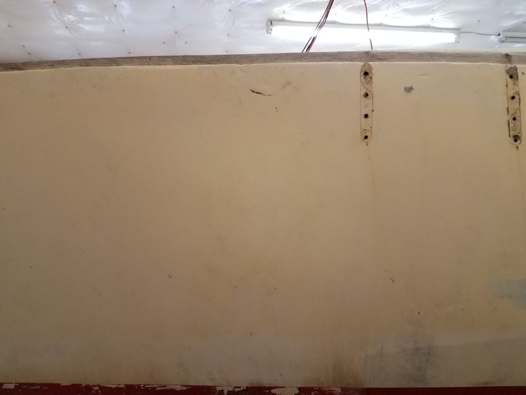
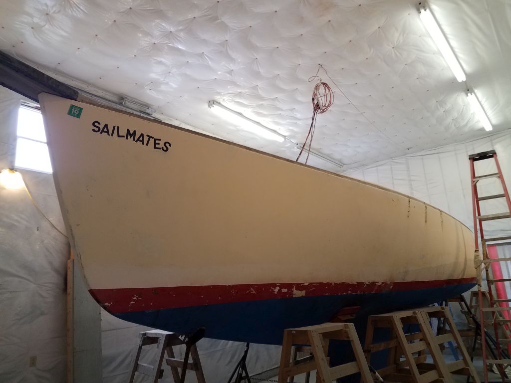
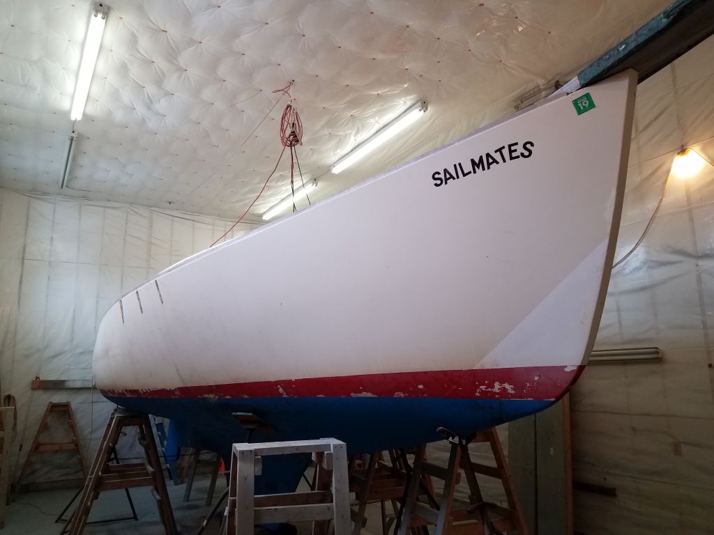
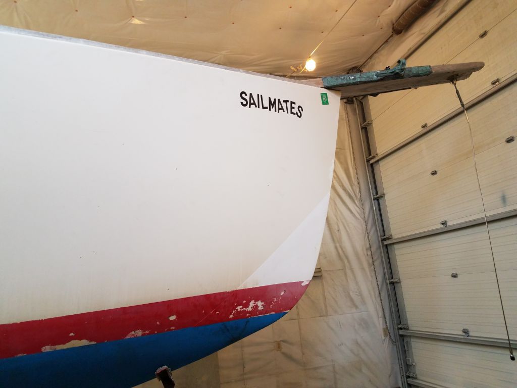
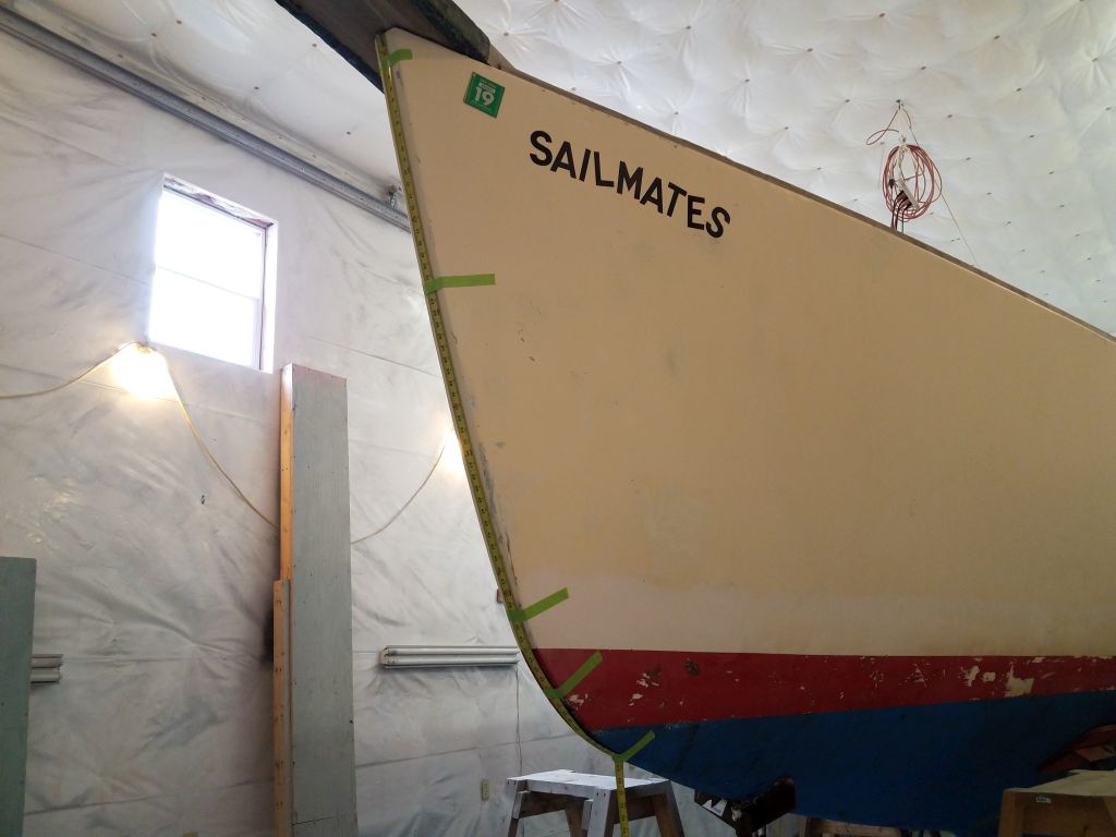
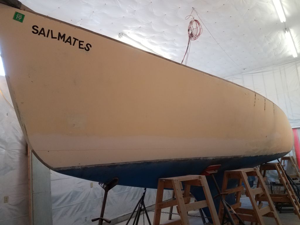
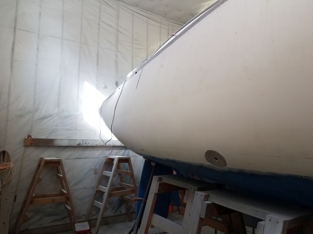
Finally ready to begin the bulk surface preparation work, towards which all the dismantling had been leading, I documented once more the initial condition of the hull and boottop. Other than the obviously-repaired areas visible on the port side, the hull was original gelcoat in poor cosmetic condition, although there were no major issues visible beyond the ugly repair work to port. There was a strange sort of raised edge on the starboard bow, clearly visible and with a hard edge of about 1/16″ in height. This area ended right at the bottom of the boottop, and extended in an angle a couple feet up the stem. I’d no idea what that was about, but would streamline the area during the surface prep ahead.
The rest of the boottop was in poor condition and had clearly spent its life nearly or partially submerged over much of the length of the boat, with widespread coating failure. The repair work on the port side, while ugly on the surface, didn’t look like anything recent, and so far there’d been no signs of a continuing problem. Otherwise, the hull was simply worn out and tired in appearance, with the usual collection of minor surface interruptions common to boats of nearly any age.
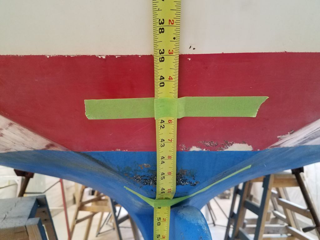
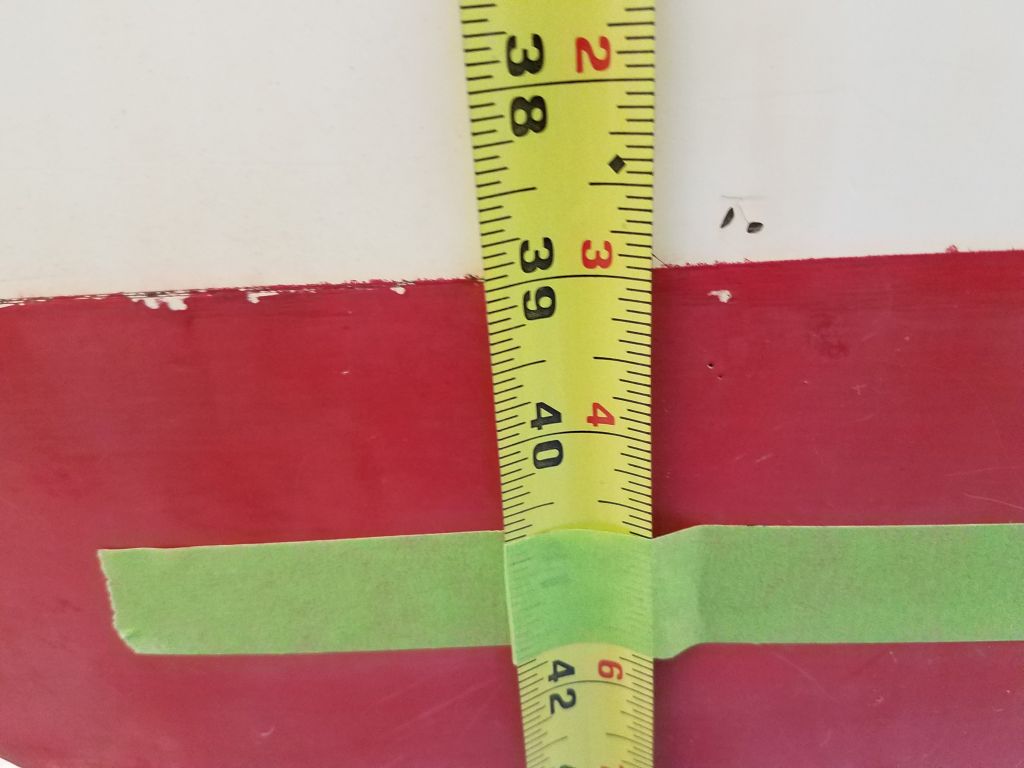
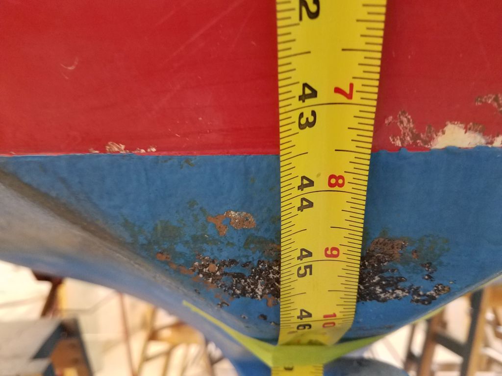
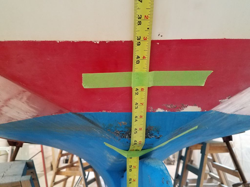
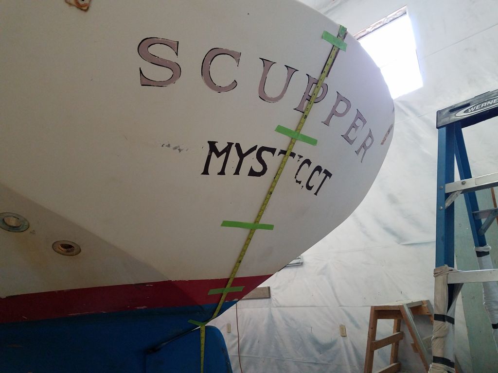
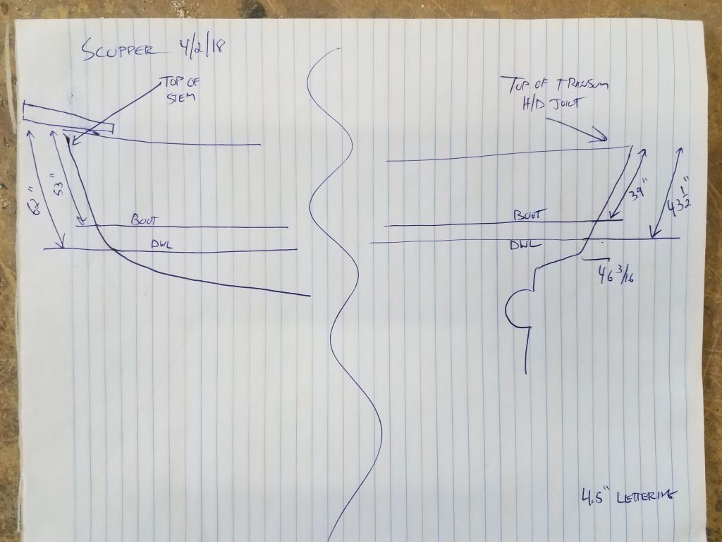
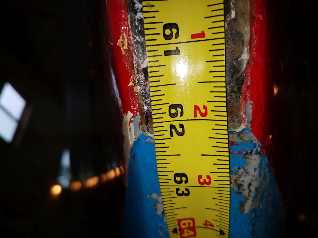
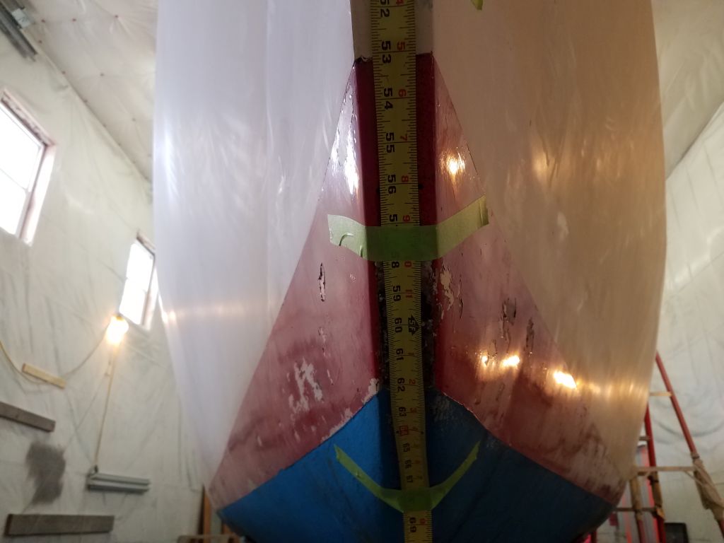
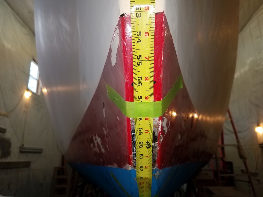
Before beginning, I made reference measurements to document the existing locations of the waterline (i.e. top edge of the bottom paint) and boottop above. At the stern, there was the remnant of a scum line clearly visible to help suggest actual floating level there, and similar indicators elsewhere, largely on the boottop. In any event, I used a tape measure from easily-reproducible locations to record the existing locations for future reference.
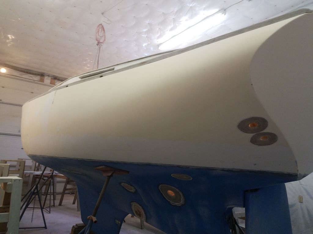
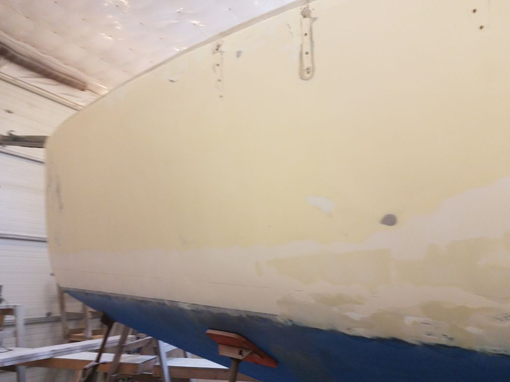
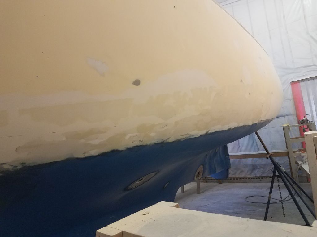
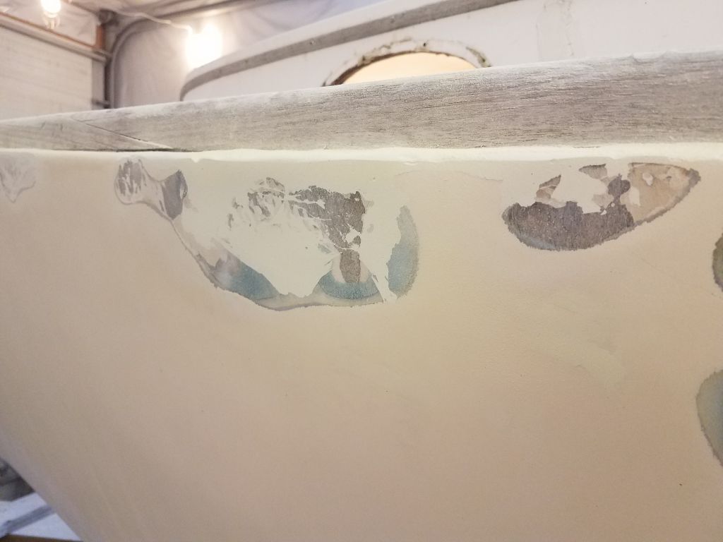
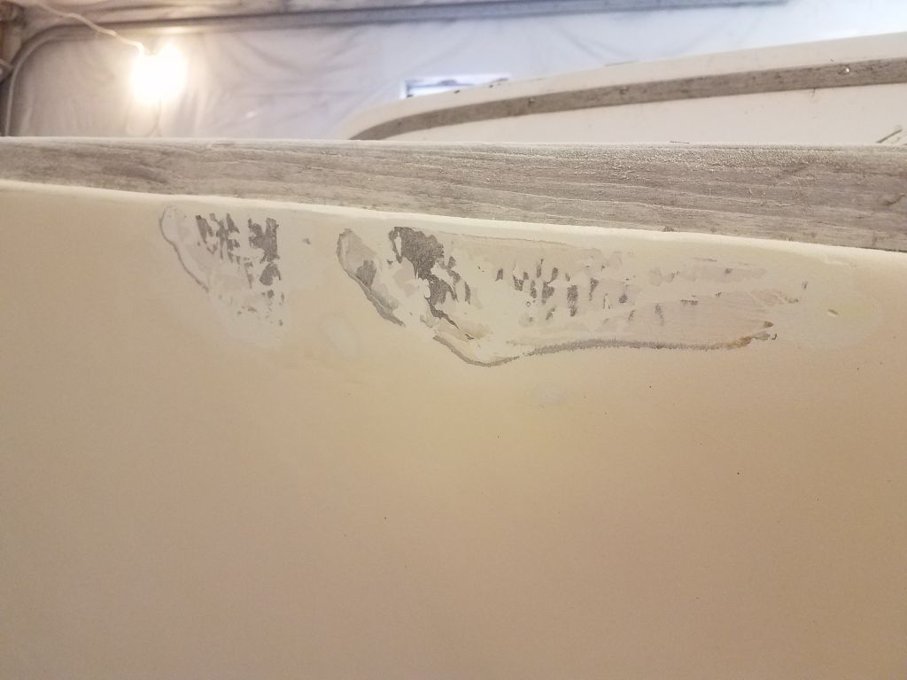
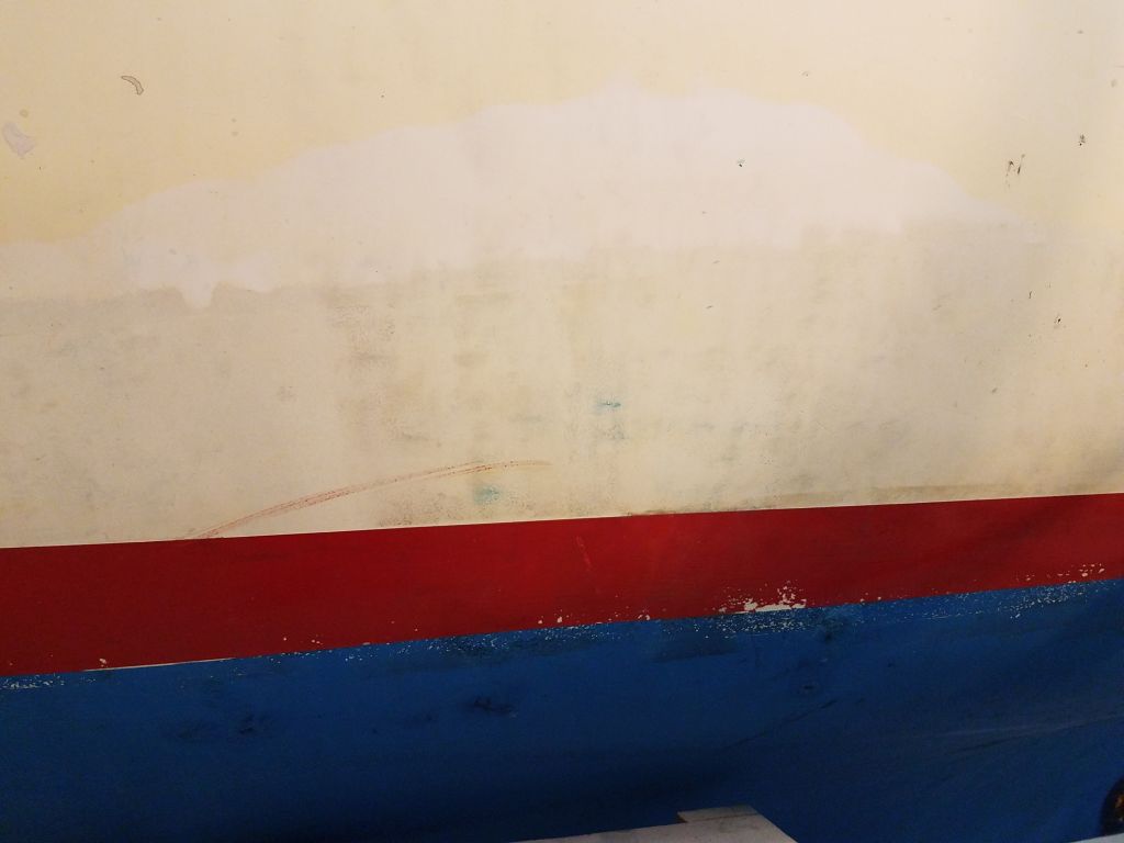
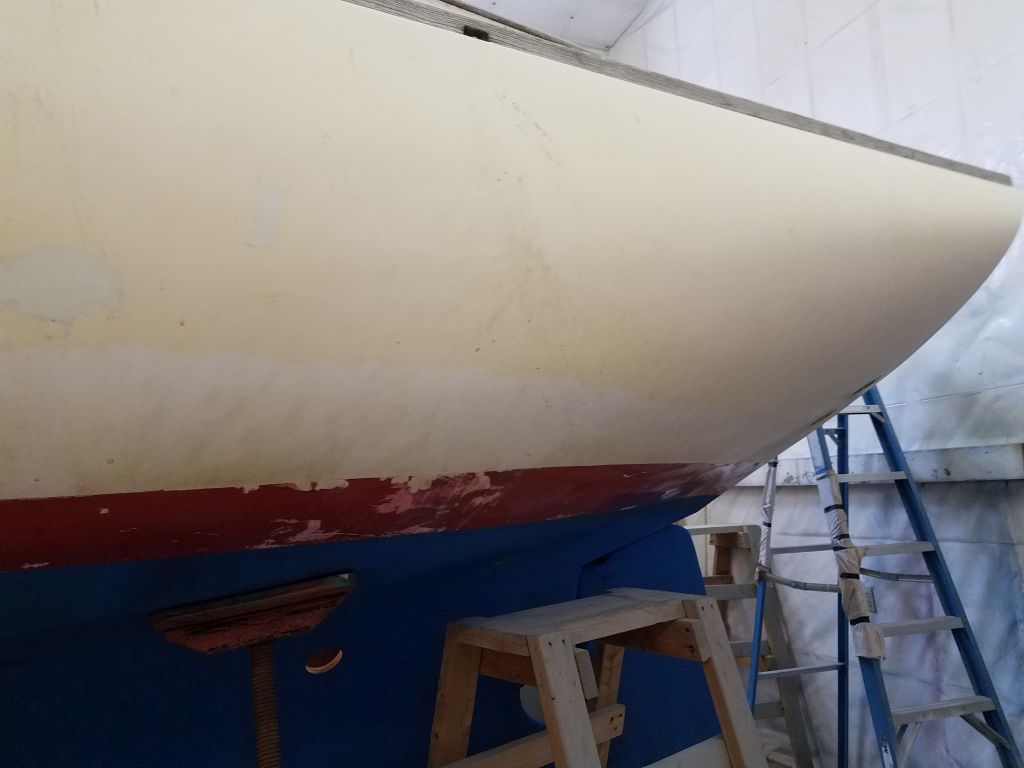
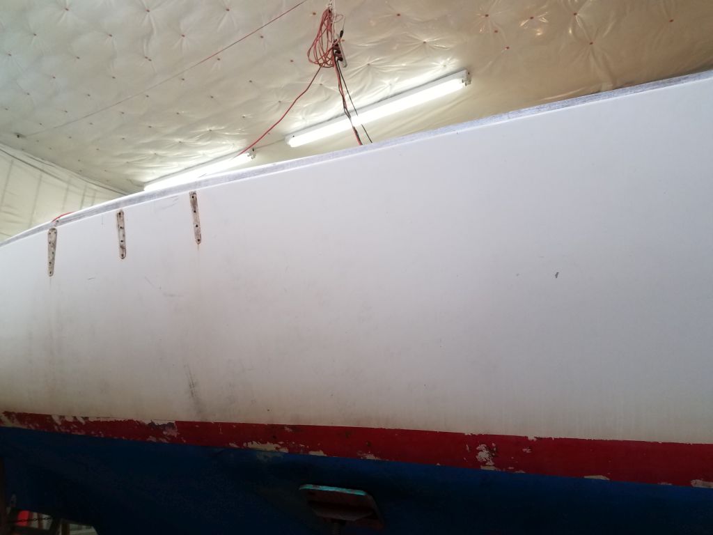
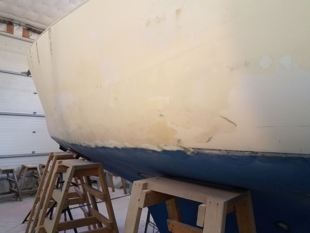
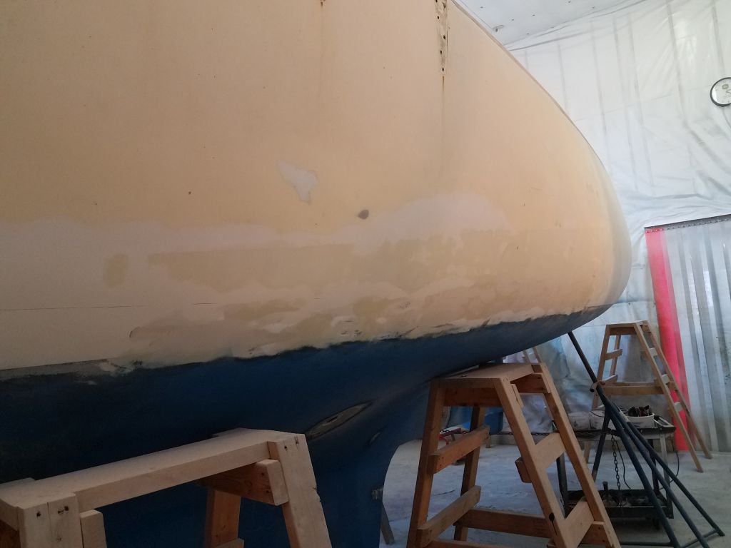
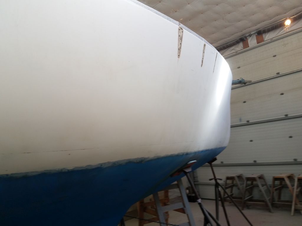
Now, working from ground level, I began the hull work by sanding off the old boottop paint, a two-grit process to avoid going too far with the coarser grits since the hull above was just soft gelcoat and would require less aggressive sanding to prepare. Once I’d worked around the hull along both sides to remove the paint, I switched to a different sander and repeated the process, this time reaching up as far on the hull as I could (about 18″ above the waterline, or just below the hailport or to the top the through hulls in the port counter in these photos) with 80 and 120 grits on a 6″ finishing sander, cleaning up the hull and removing any (ha ha) gloss to prepare for future work.
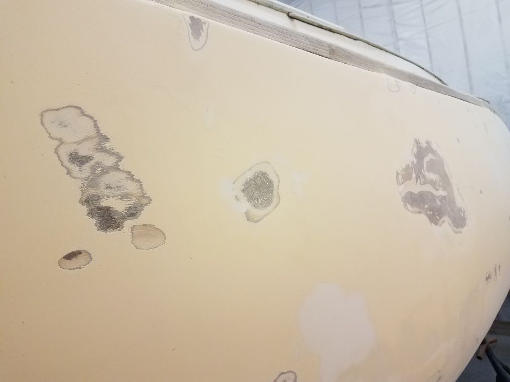
Sanding the lower portion of the repair work on the port side, mainly amidships, didn’t reveal any undue surprises, and while these repairs had been unsightly blemishes on the hull, so far it looked sound enough, and appeared only to require additional cosmetic fine-tuning and minor fairing to prepare for refinishing later. The existence of this repair had been obvious all along, from both inside and out, so at least I’d not been surprised by any new findings just yet.
With the ground-level work complete at the end of the day, I planned to set up staging and continue working my way up the hull next time.
Total time billed on this job today: 7.5 hours
0600 Weather Observation: Cloudy, 30°. Forecast for the day: Clouds, then slow clearing, around 40°
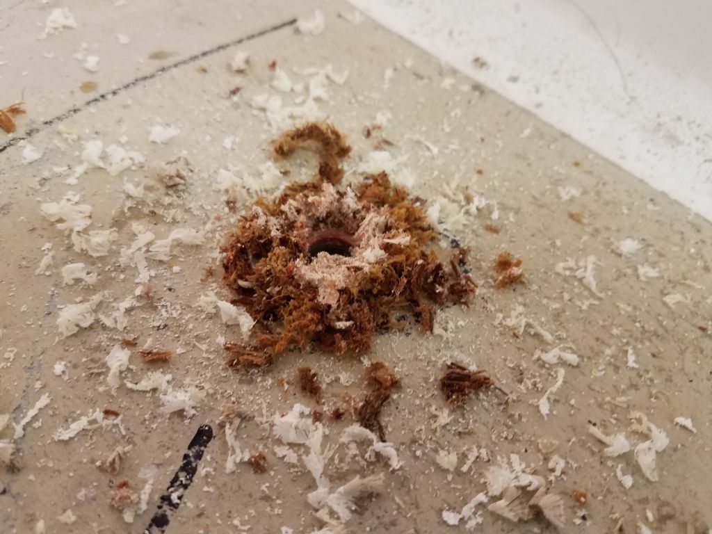
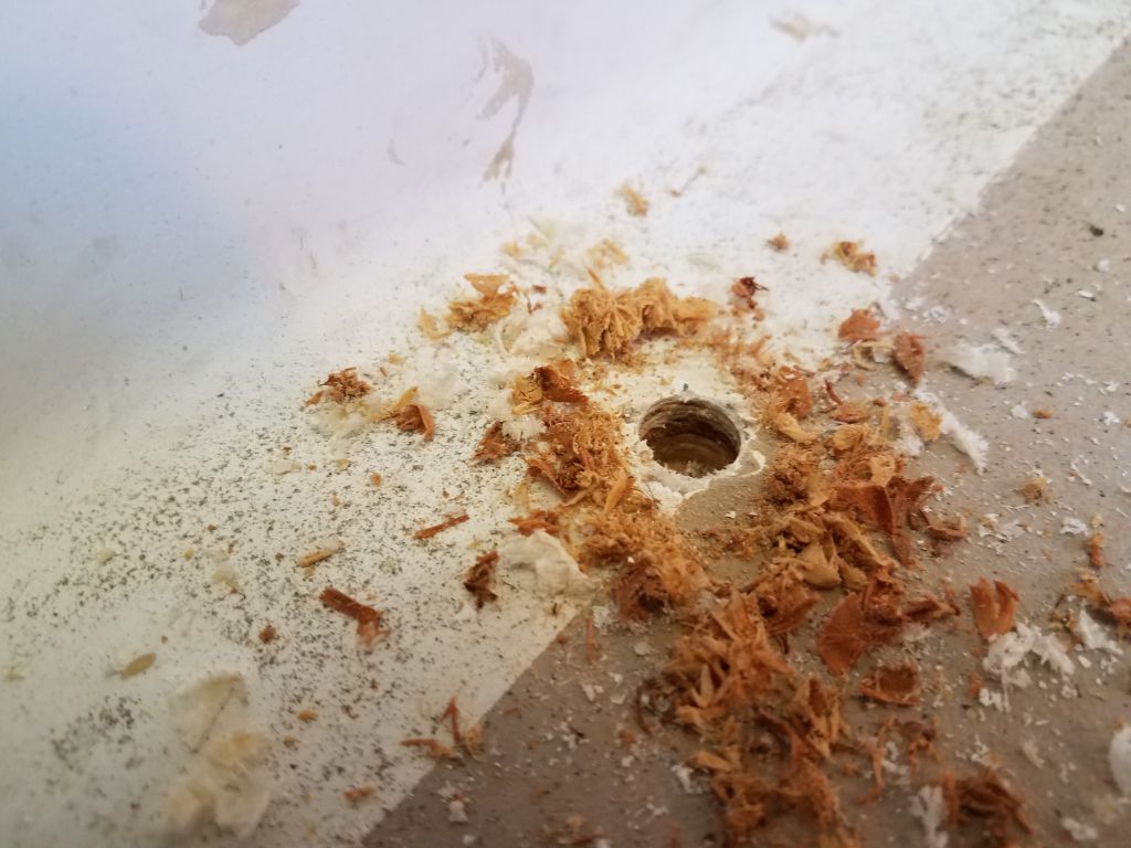
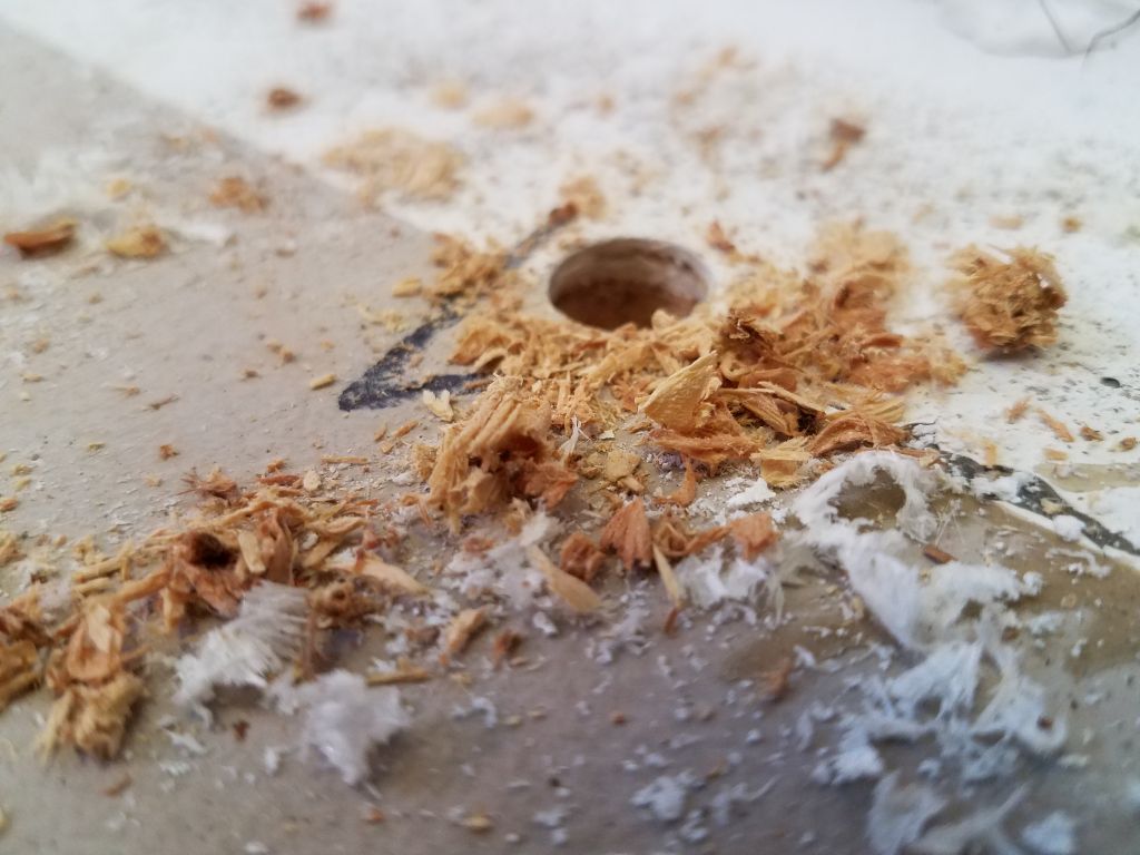
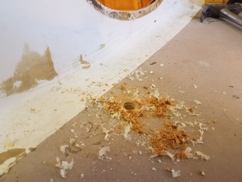
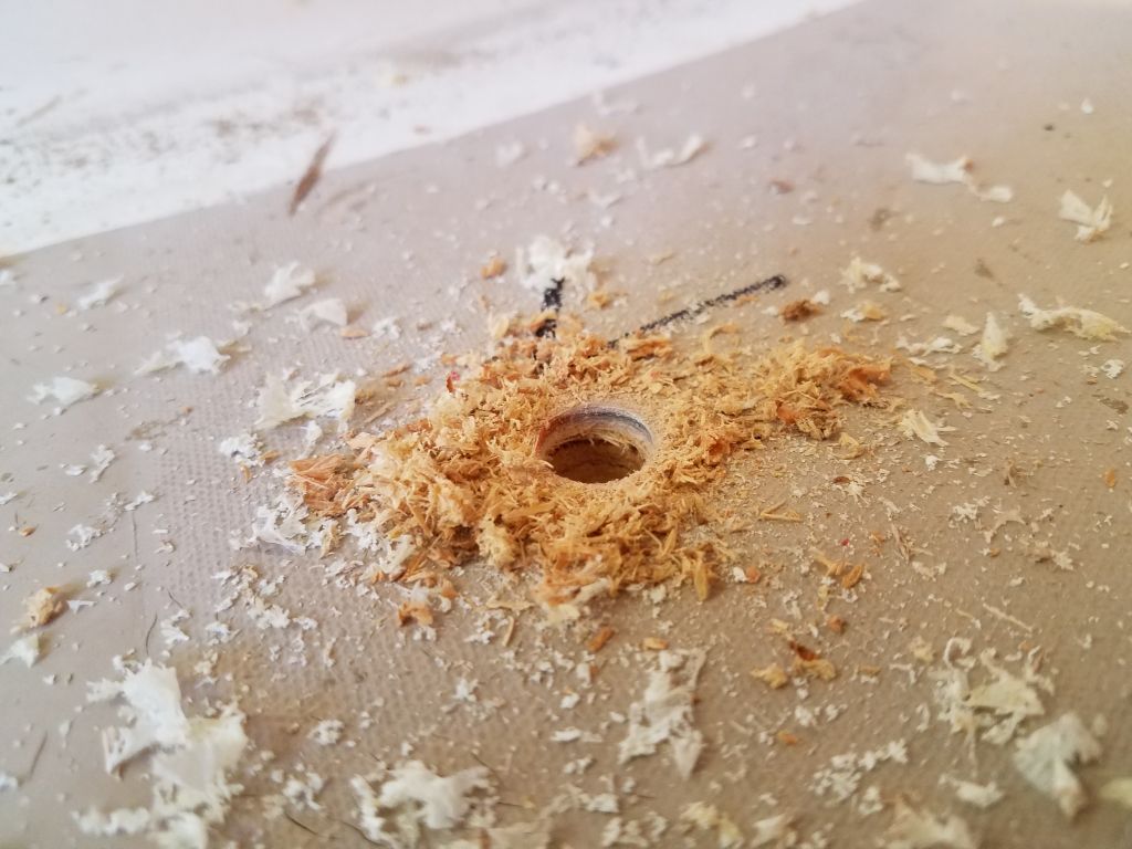
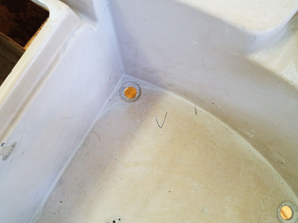
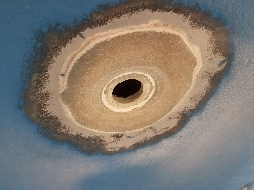
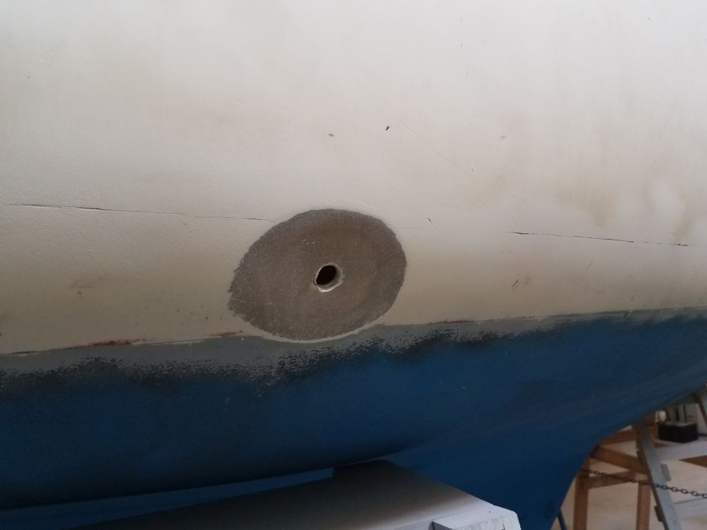
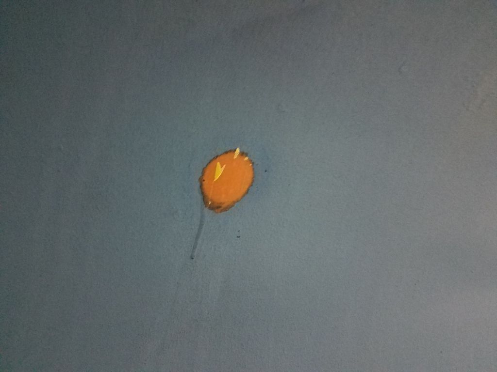
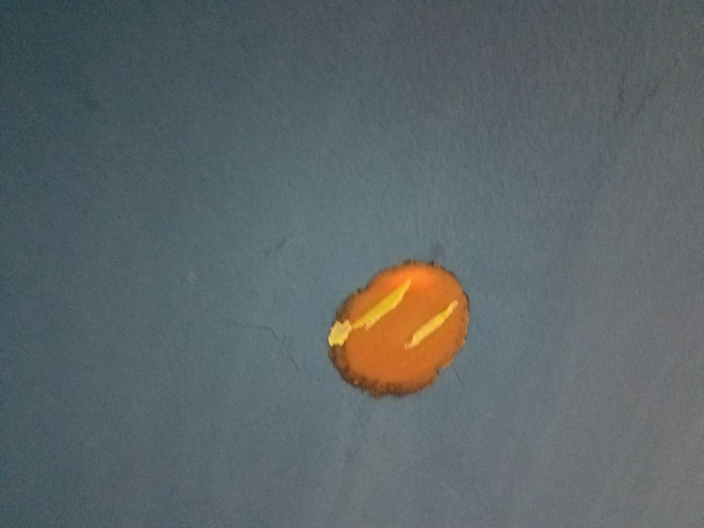
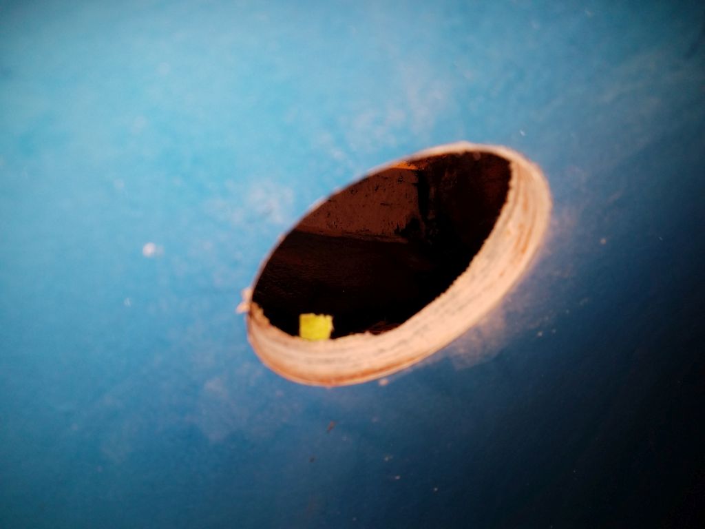
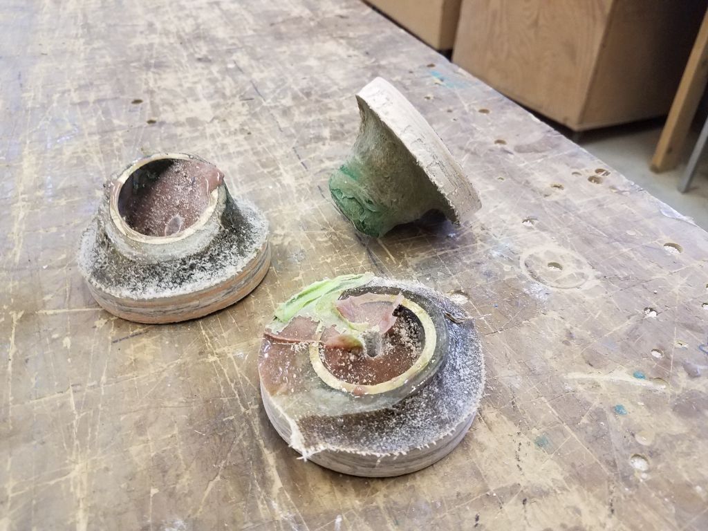
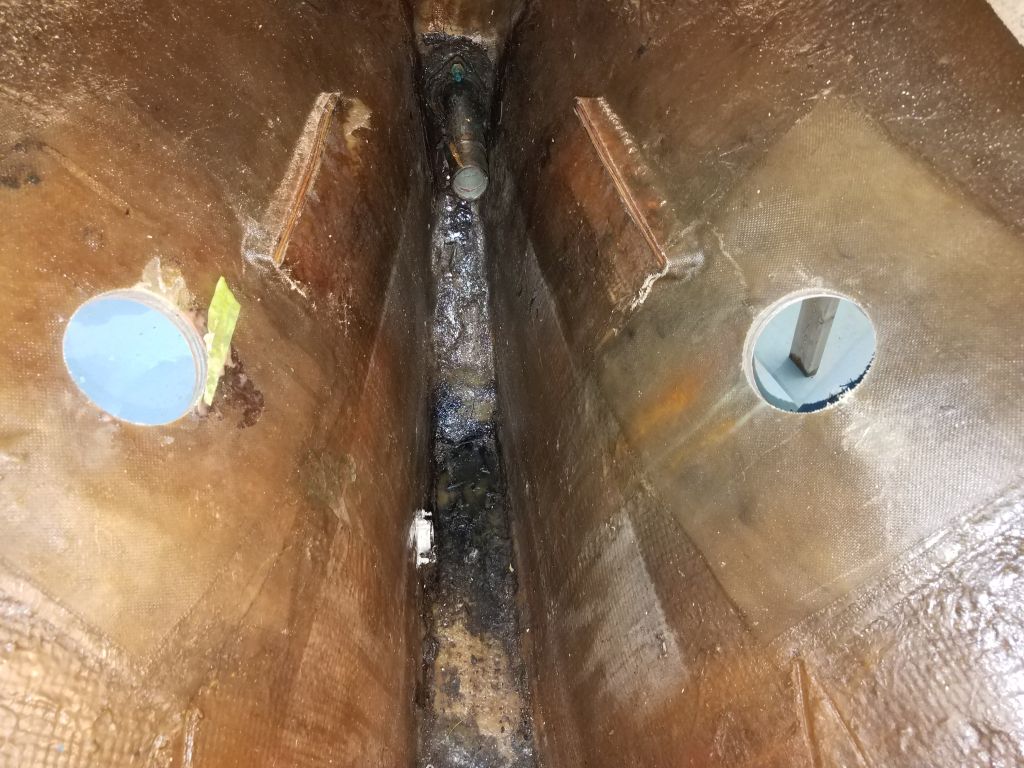
After a day away on another project, the epoxy in the three bronze through hulls (cockpit scuppers and galley sink, all of which were glassed in place) had cured, and left me with the little plugs I needed so I could center a hole saw and remove the fittings.
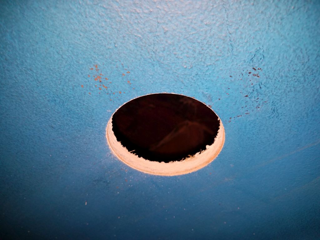
With a 3″ hole saw that was wide enough to encompass the entire heads of these fittings (assuming they existed), I removed the three fittings, leaving clean holes that I’d patch later.
Just a bit of trim remained in the forward cabin, and now I removed it.
I’d agitated the bilge water and detergent a few times over the past couple days, loosening the accumulated grime, and now I drained the bilge. The forward bilges beneath the main cabin cleaned up fairly well, considering, and I rinsed the detritus aft so I could clean it all out from the engine room. Now the bilges could air out and dry over the weekend.
I spent a little time contemplating the bowsprit and whether to remove it or not. It was in fair, but weathered, condition, with some minor damage at the forward end on the bottom side (not visible here), but I didn’t relish the task of unnecessarily removing it, as access to the underside was tight through a small opening in the chainlocker bulkhead. For now, with no pressing need for its removal nor any obvious reasons requiring it, I decided to leave it in place pending further work and to see if something came to light later that might require the removal.
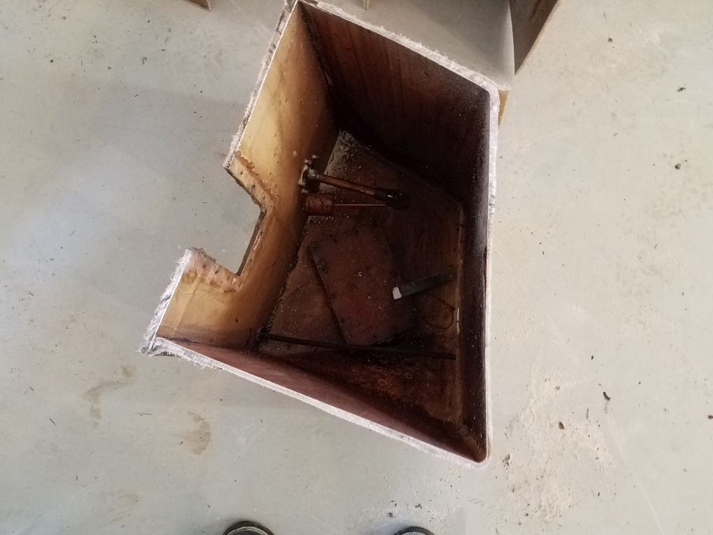
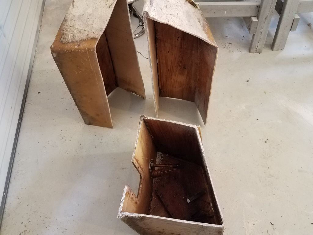
Finally, I cut apart the fiberglass fuel tank so I could dispose of it.
Total time billed on this job today: 2.75 hours
0600 Weather Observation: 40°, foggy. Forecast for the day: Light rain in the morning, then improving, temperatures in the 50s