Wednesday
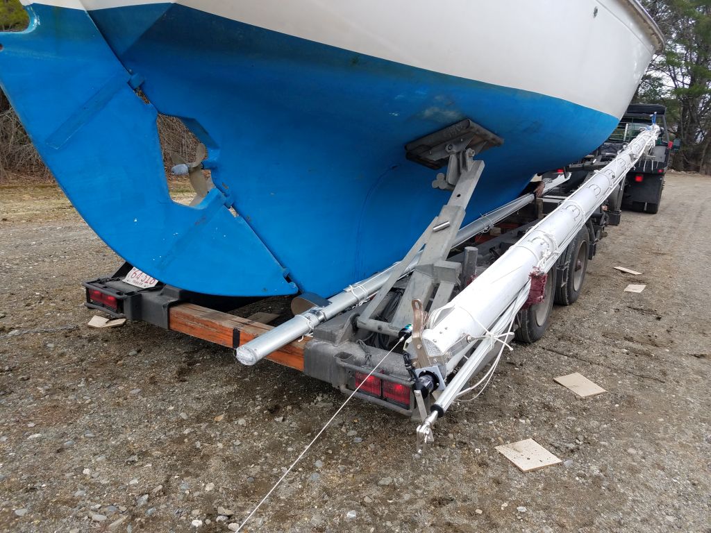
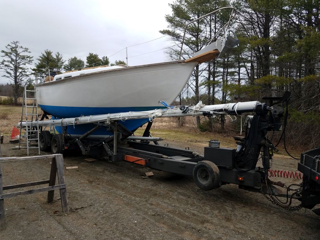
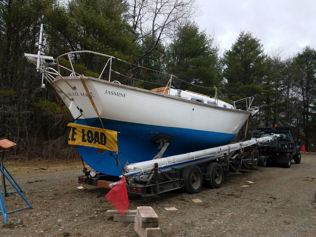
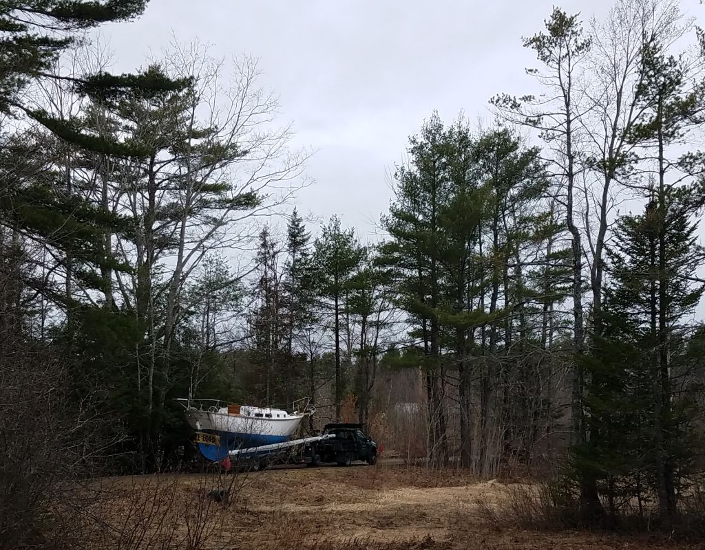
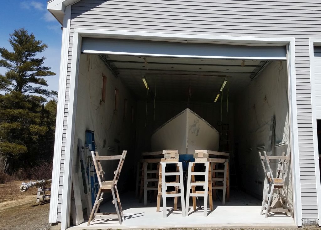
With all work complete, including all-new rigging that had been completed in the weeks since I moved the boat outdoors, Jasmine departed the shop on a truck, headed for her owner’s home waters.


Wednesday
With all work complete, including all-new rigging that had been completed in the weeks since I moved the boat outdoors, Jasmine departed the shop on a truck, headed for her owner’s home waters.
Wednesday
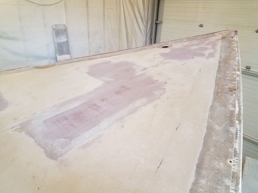
I got started with another round of sanding as needed about the decks, including the bridgedeck, coachroof, portions of the hull-deck joint, and the cockpit.

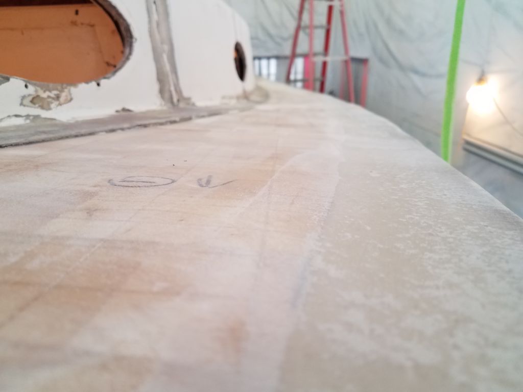


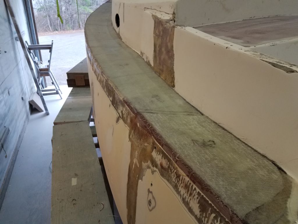
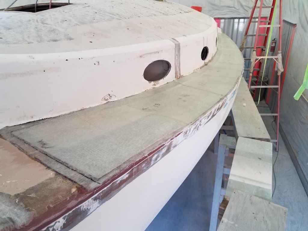
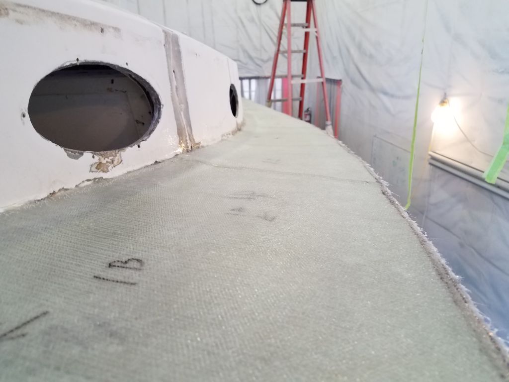
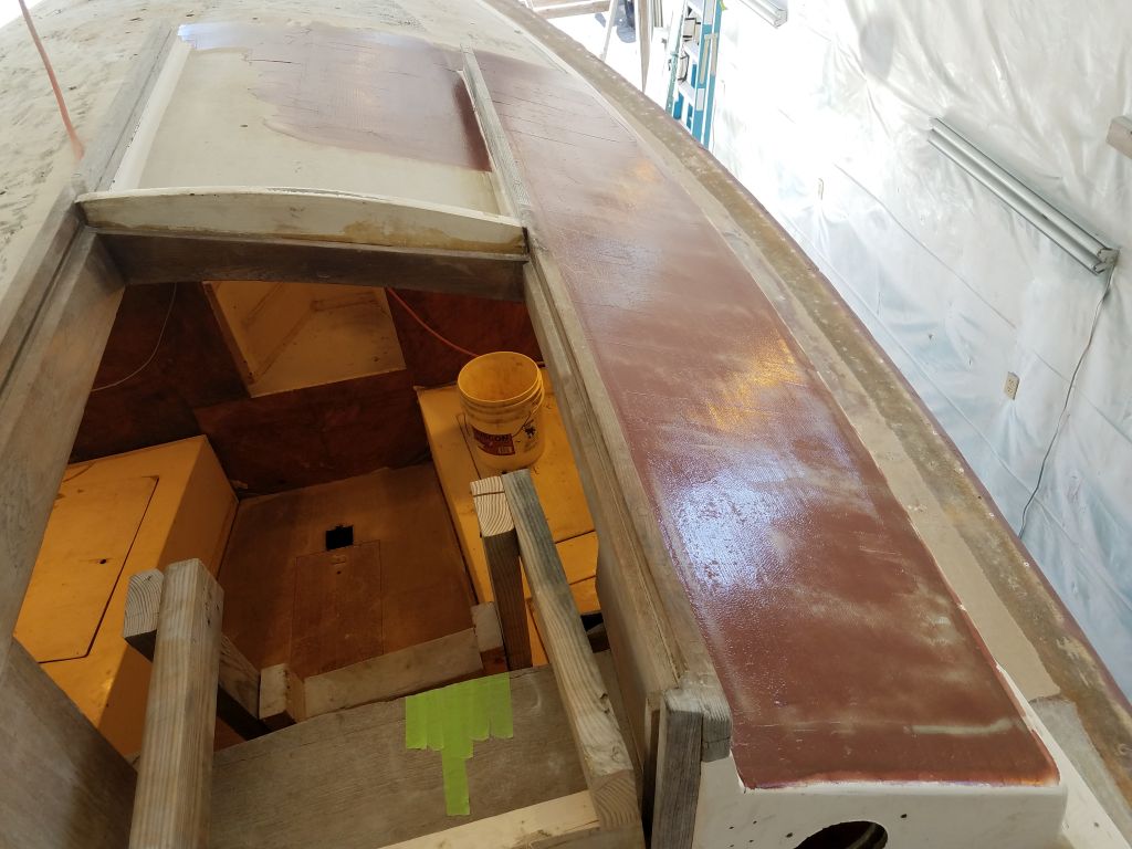
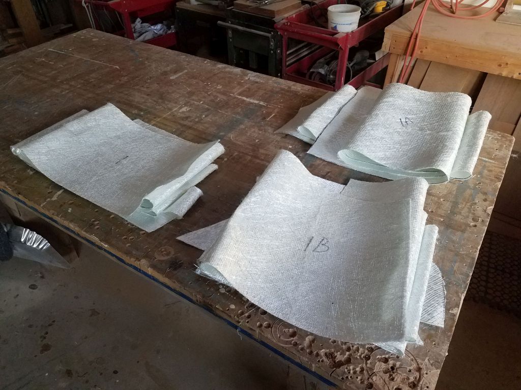
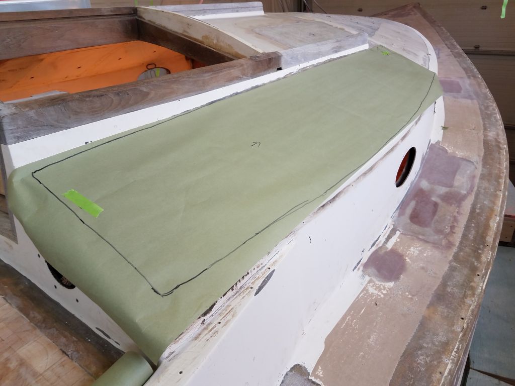
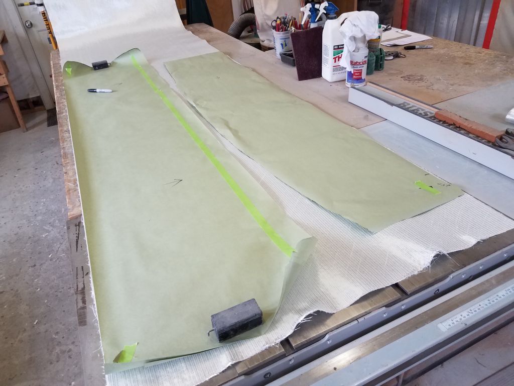
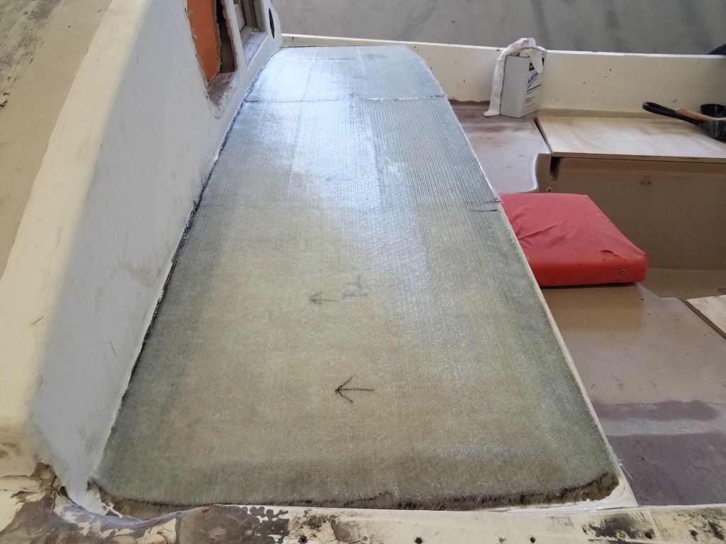
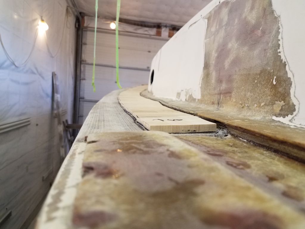
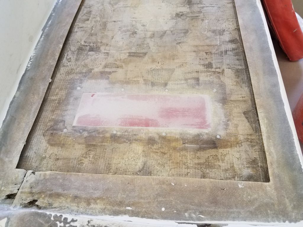
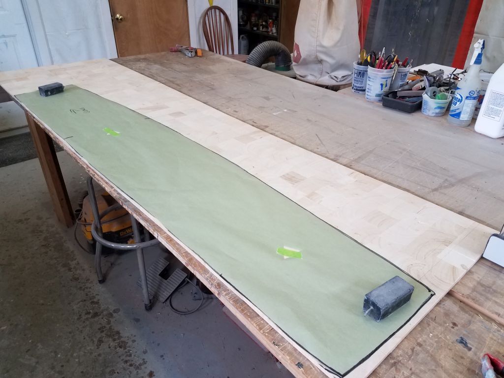
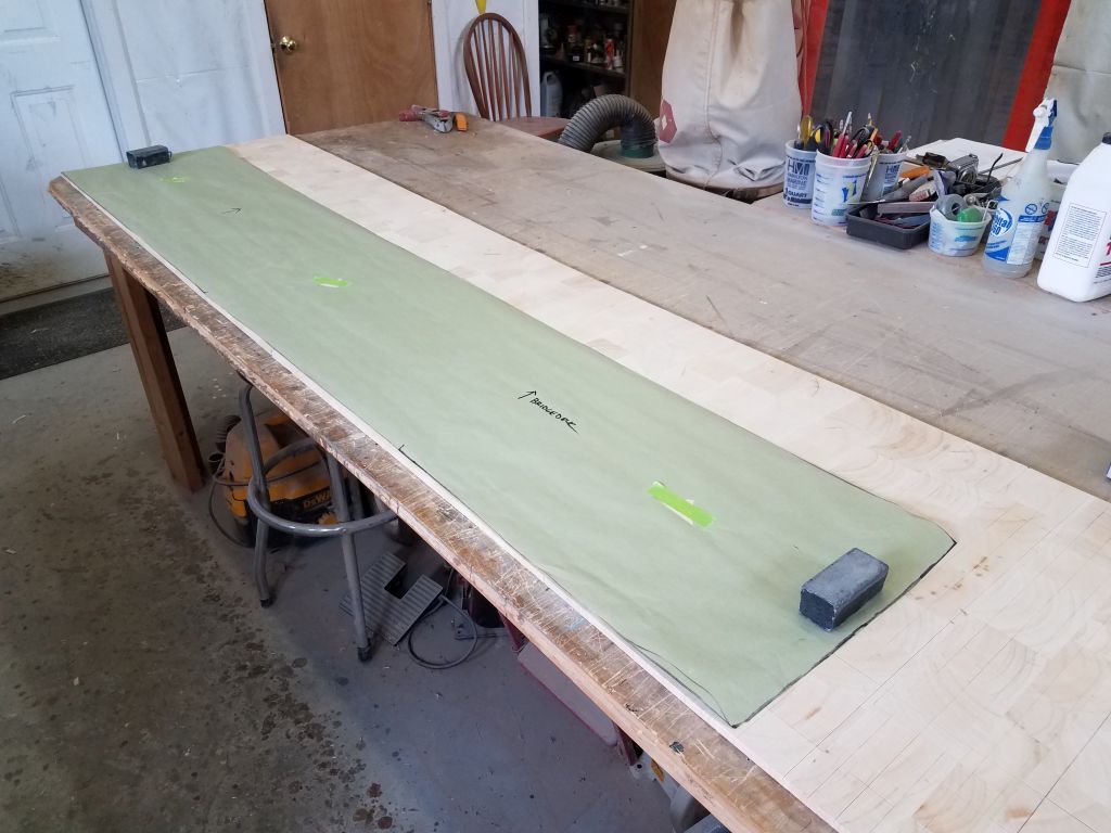
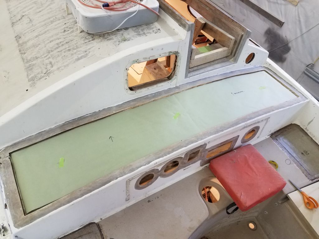
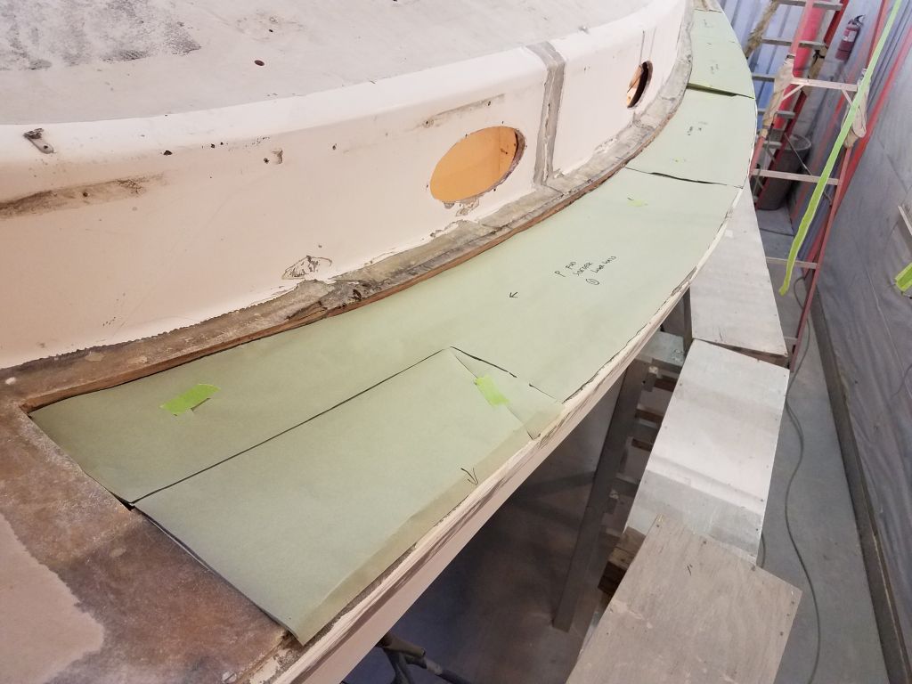
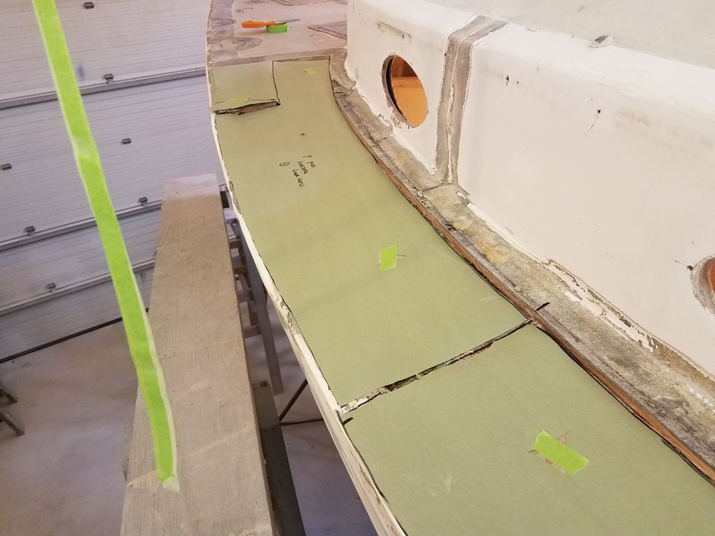
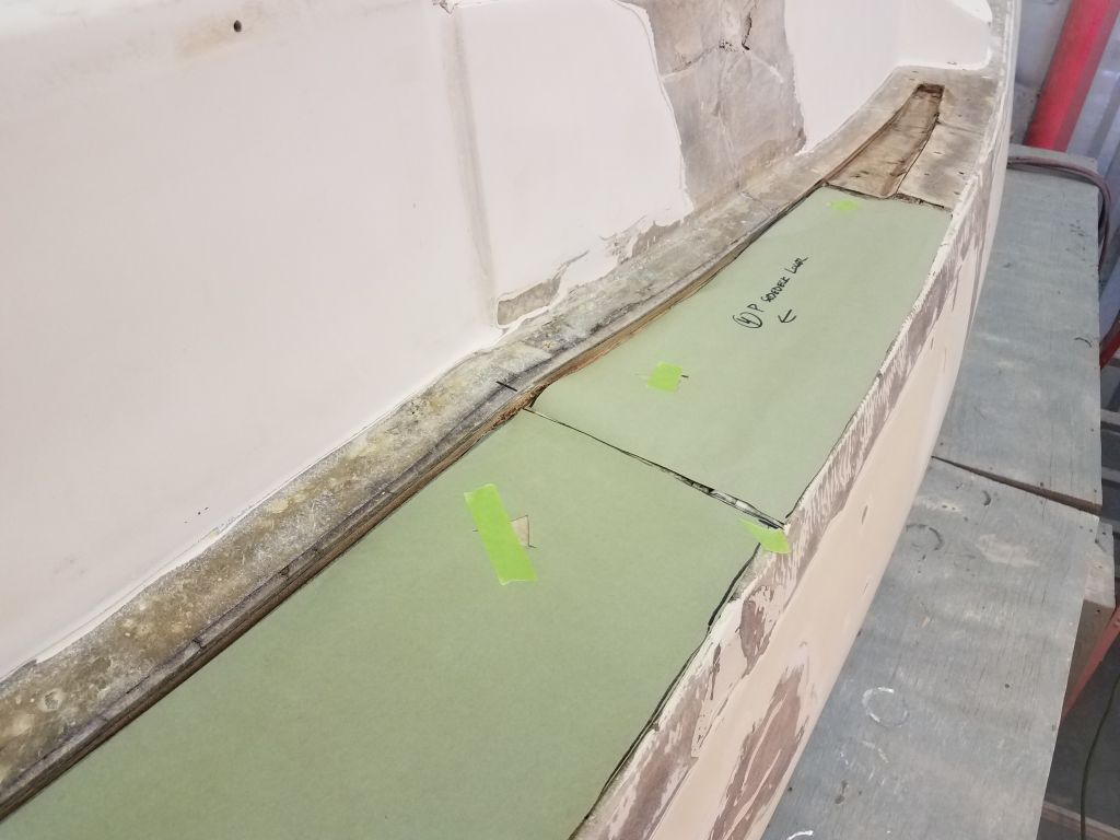
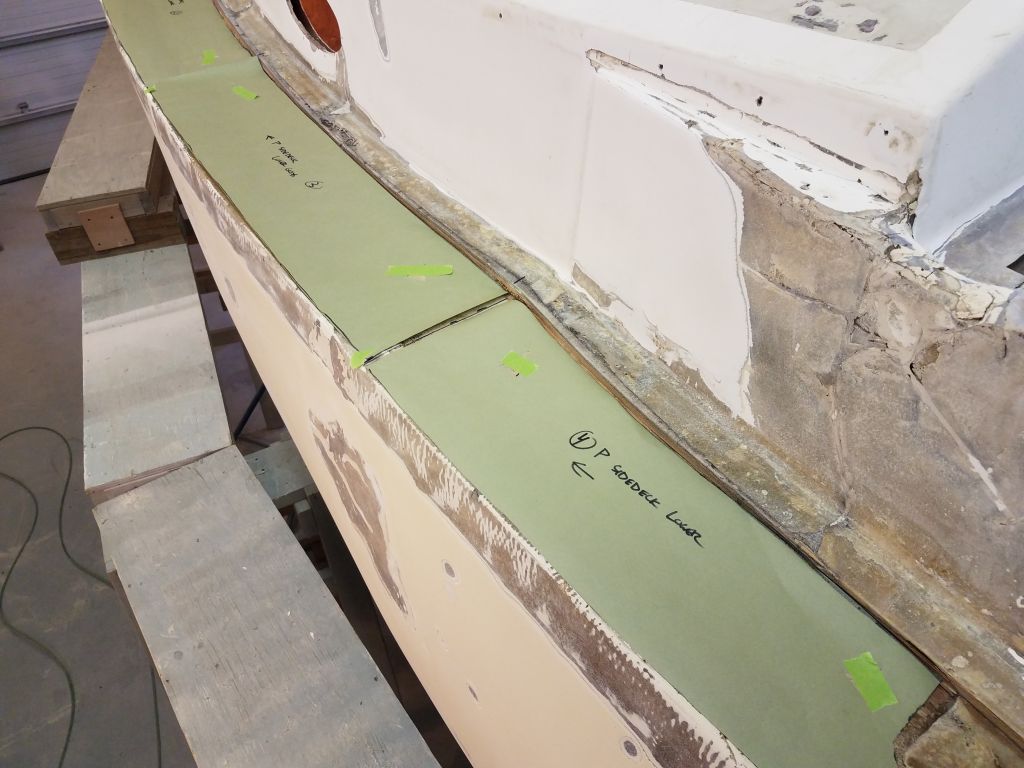
After cleaning up and other preparations, I dry-fit the three new layers of fiberglass on the port sidedeck to check the fit and to make some reference marks to help with alignment of the layers during installation. I staggered the seams between all three layers so no seam was above or near either of the other two seams between pieces of cloth.


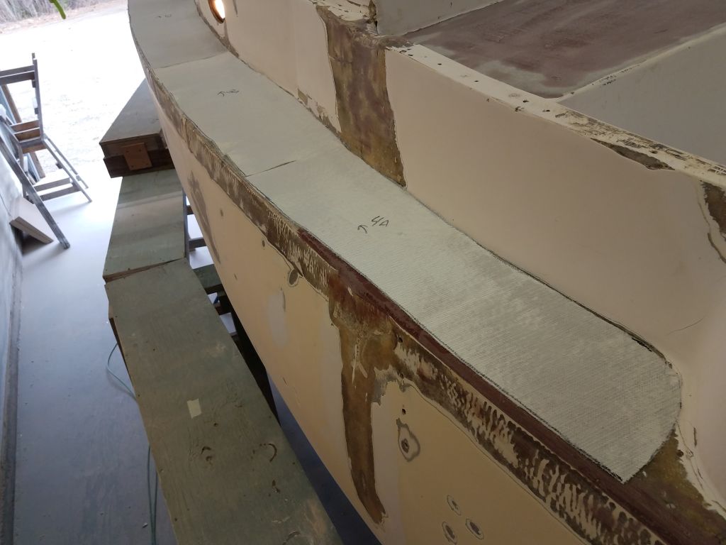

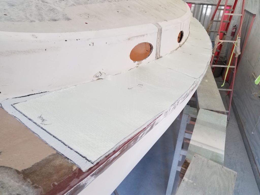
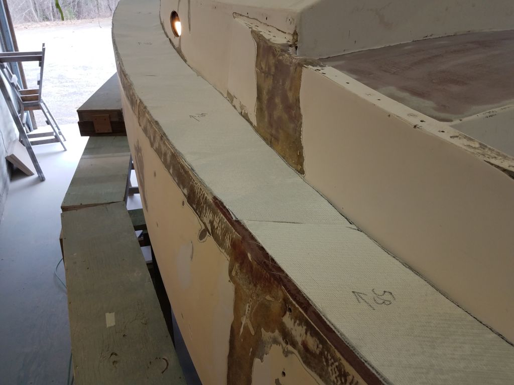
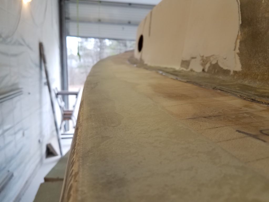
After a break while I helped and observed the departure of one of my completed projects, I spent the first half of the afternoon installing the three layers of fiberglass on the port sidedeck.


Afterwards, I applied another round of fairing filler to the other repairs as needed, mainly for the new work on the coachroof and bridgedeck, but also some minor spot-filling in the cockpit and a few areas of the hull-deck joint.


Total time billed on this job today: 6.75 hours
0600 Weather Observation: 45°, cloudy. Forecast for the day: Clouds, showers, then steady rain late in the afternoon and evening
Monday
I began with my usual round of sanding, this time the new fiberglass on the bridgedeck and coachroof, and around the new core on the port sidedeck, along with portions of the hull/deck joint. Some portions of the filled joint on the port side were now basically complete, with two applications of filler, and where possible I rounded the edge to the final contours.


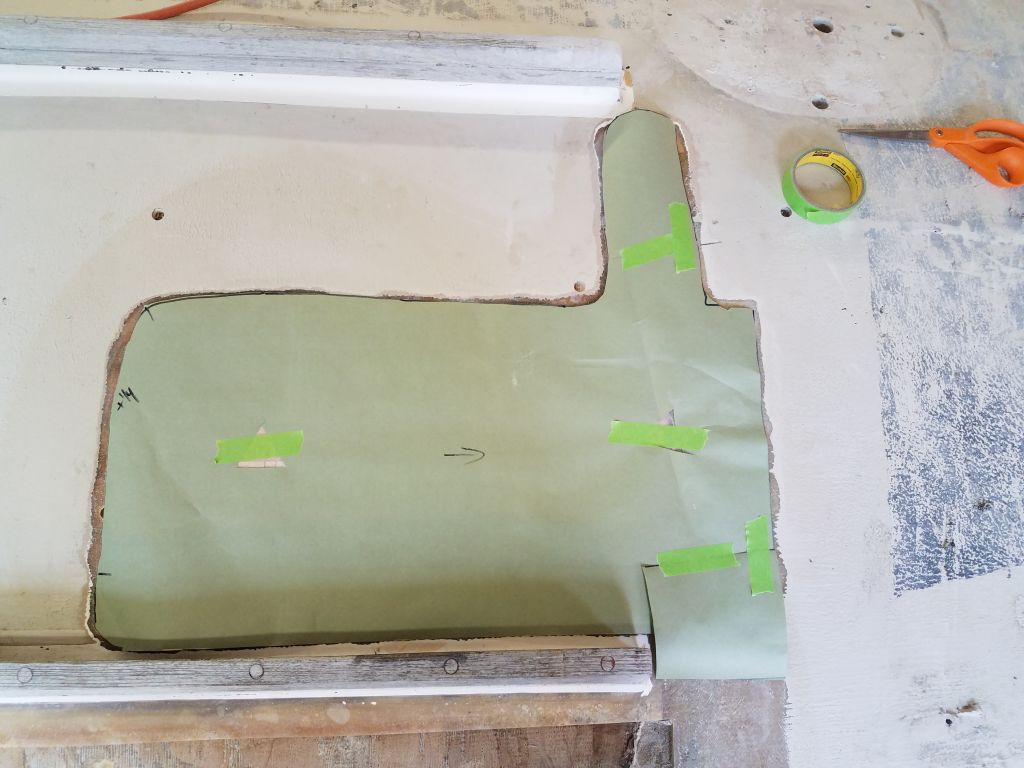
After cleaning up, I made a quick paper pattern of the port sidedeck so I could cut the new fiberglass a little later in the day.

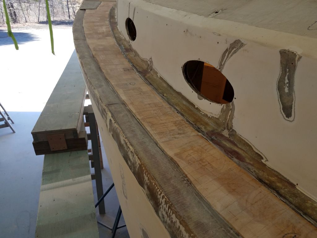
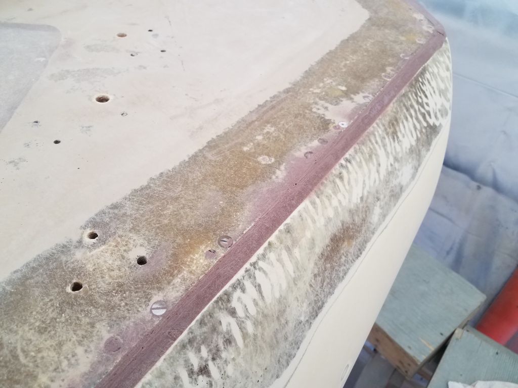
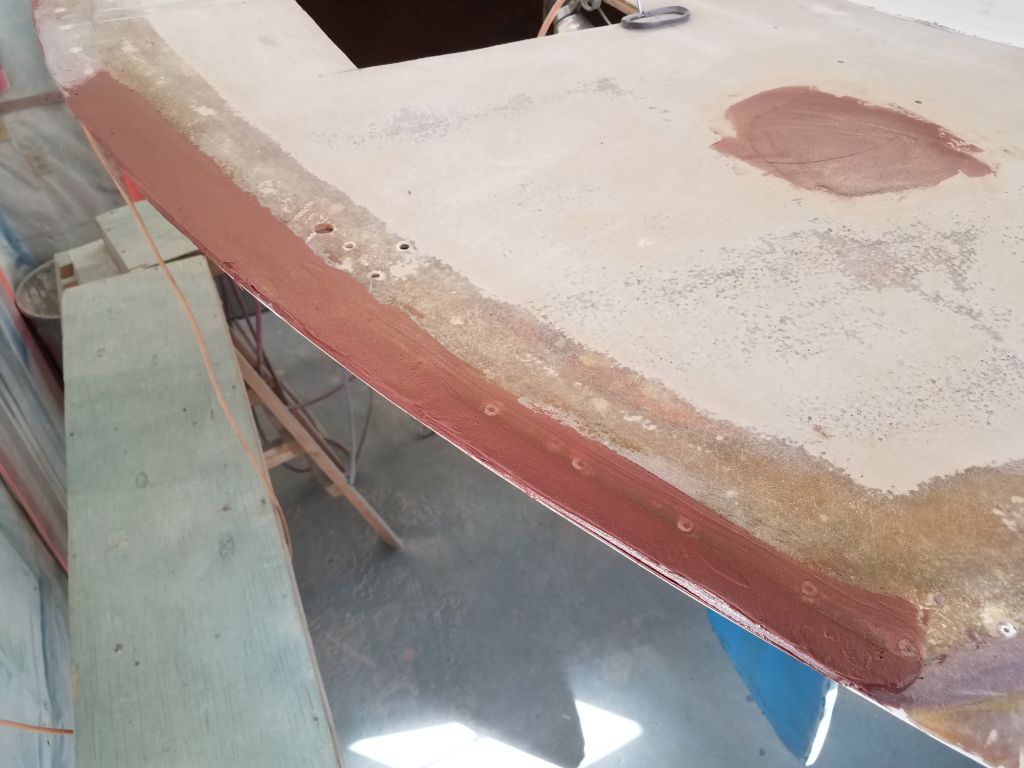
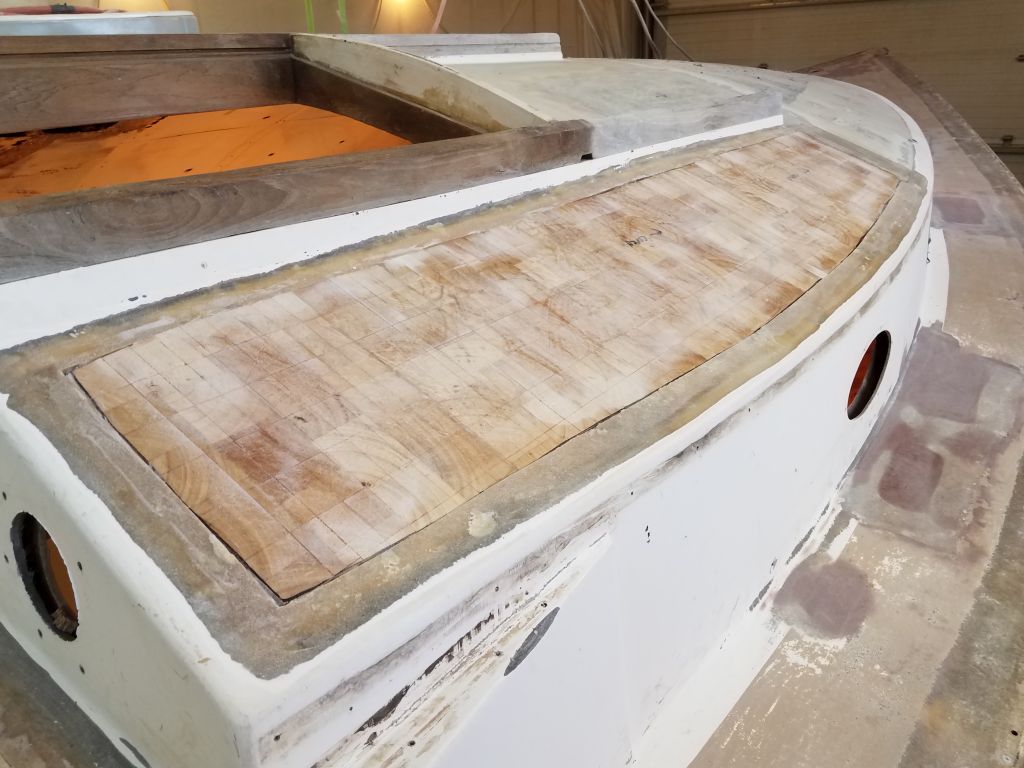
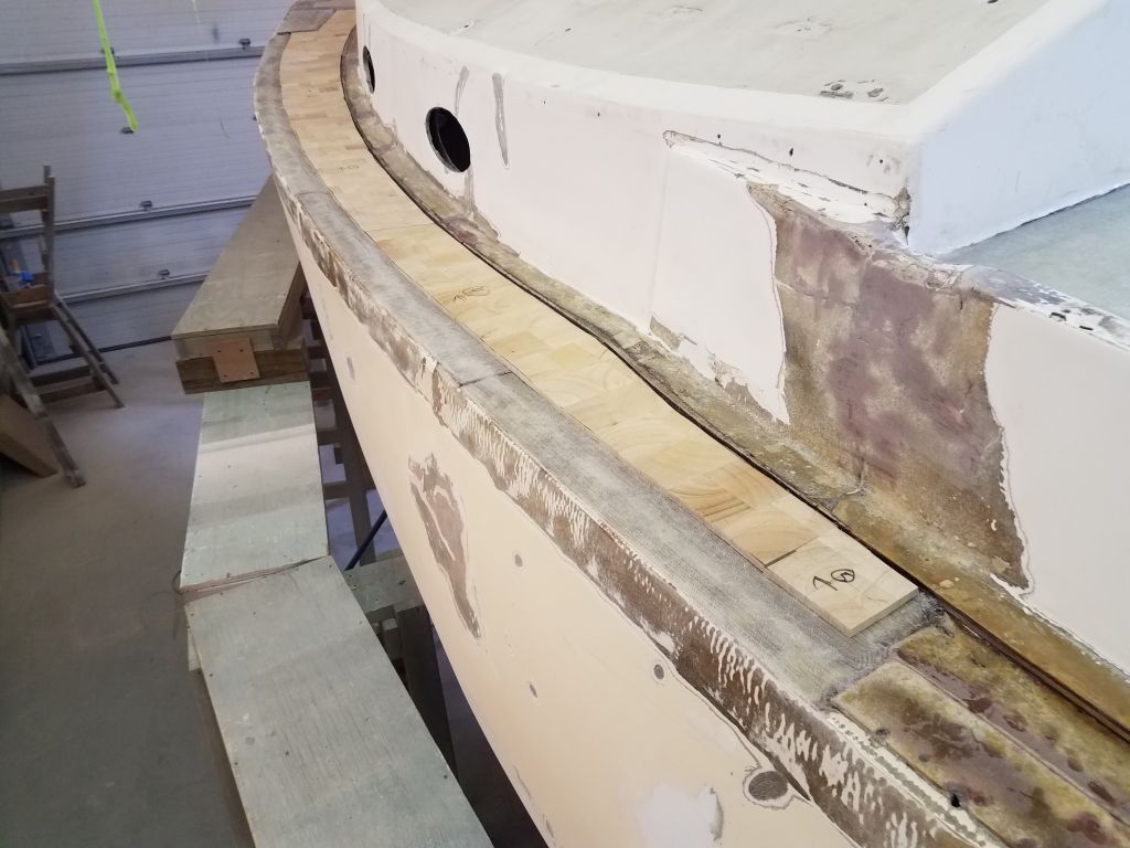
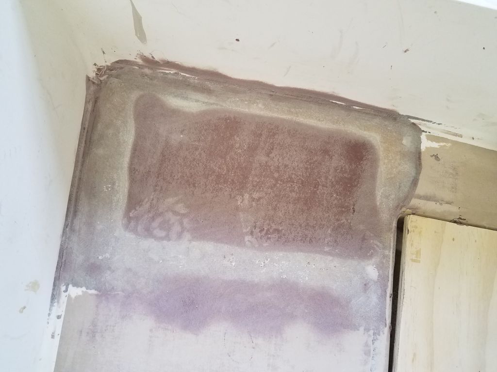
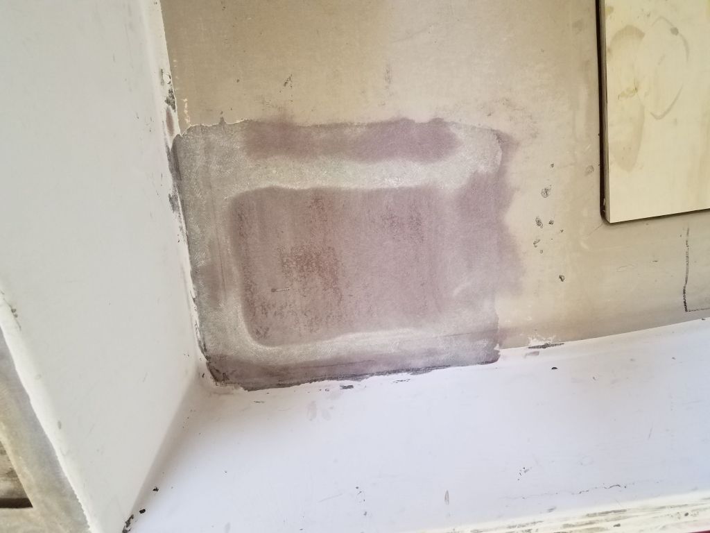
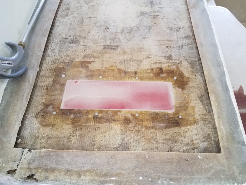
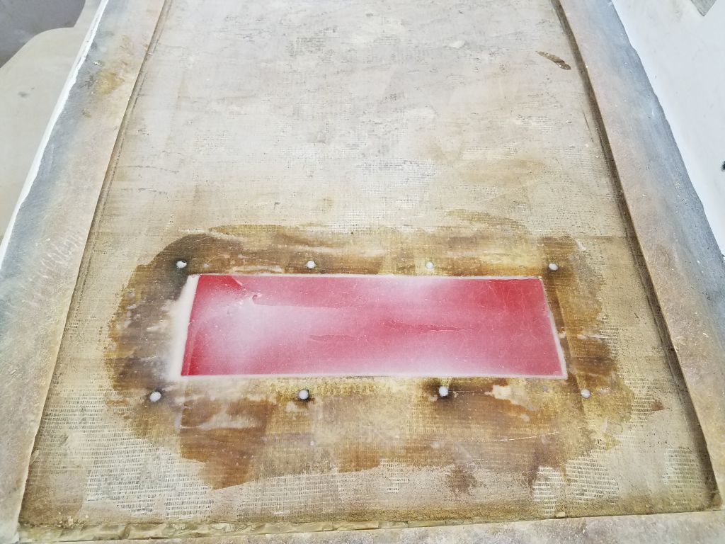
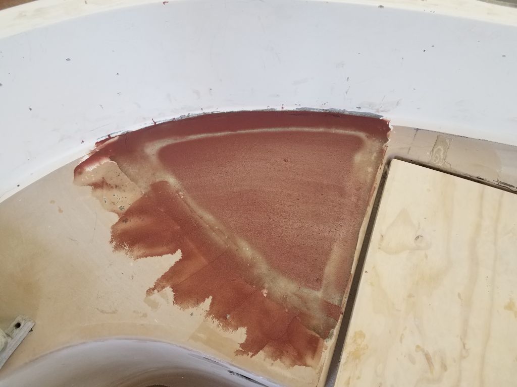
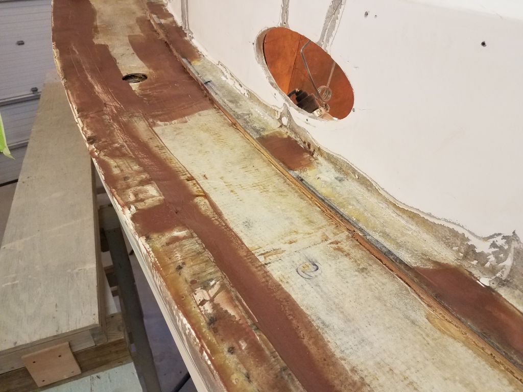
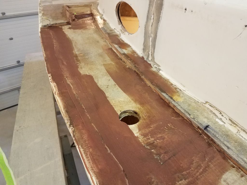
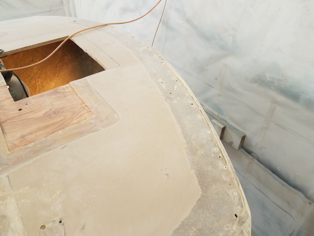
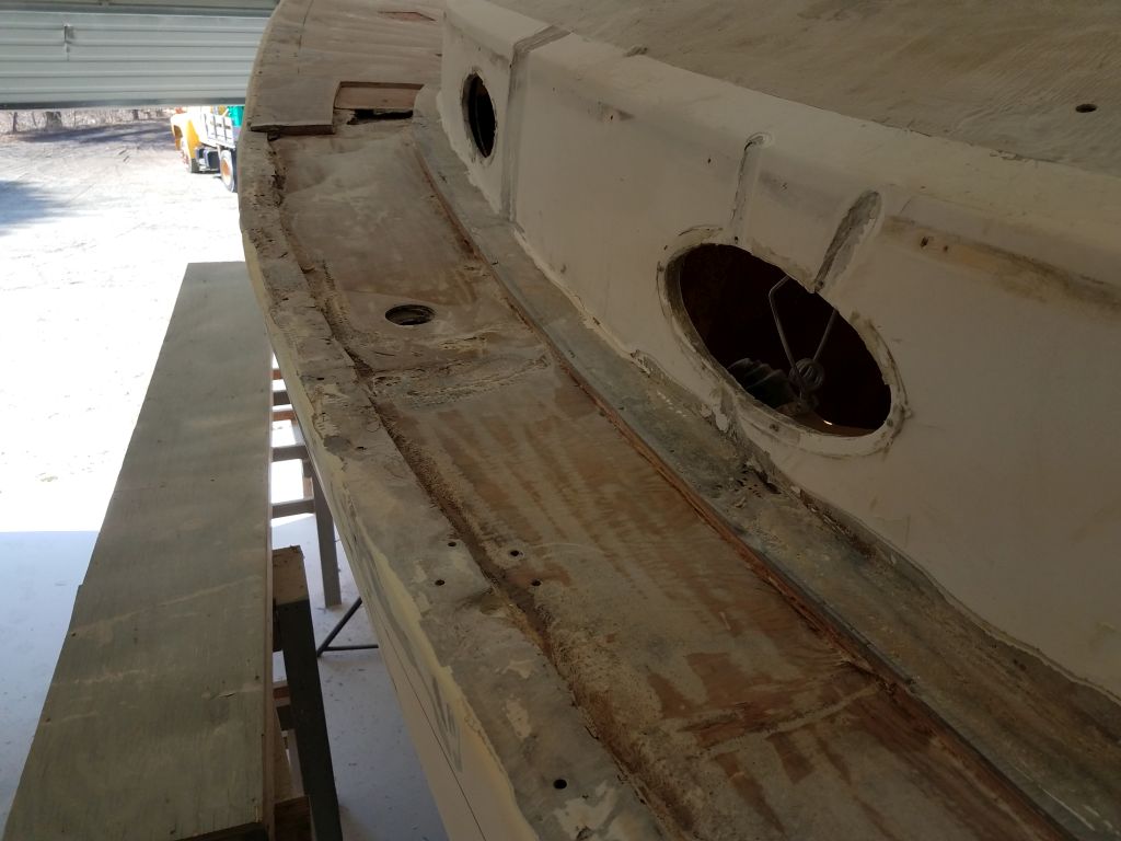
To provide a smooth transition between the edge of the new core and the hull flange for the new fiberglass, I used a mixture of epoxy with high-density structural filler to fill a small gap between the flange (which rose up a bit higher than the bottom skin laminate) and the top of the core. This also maintained a fair line from the edge of the existing deck flange (inboard) to the gunwale.
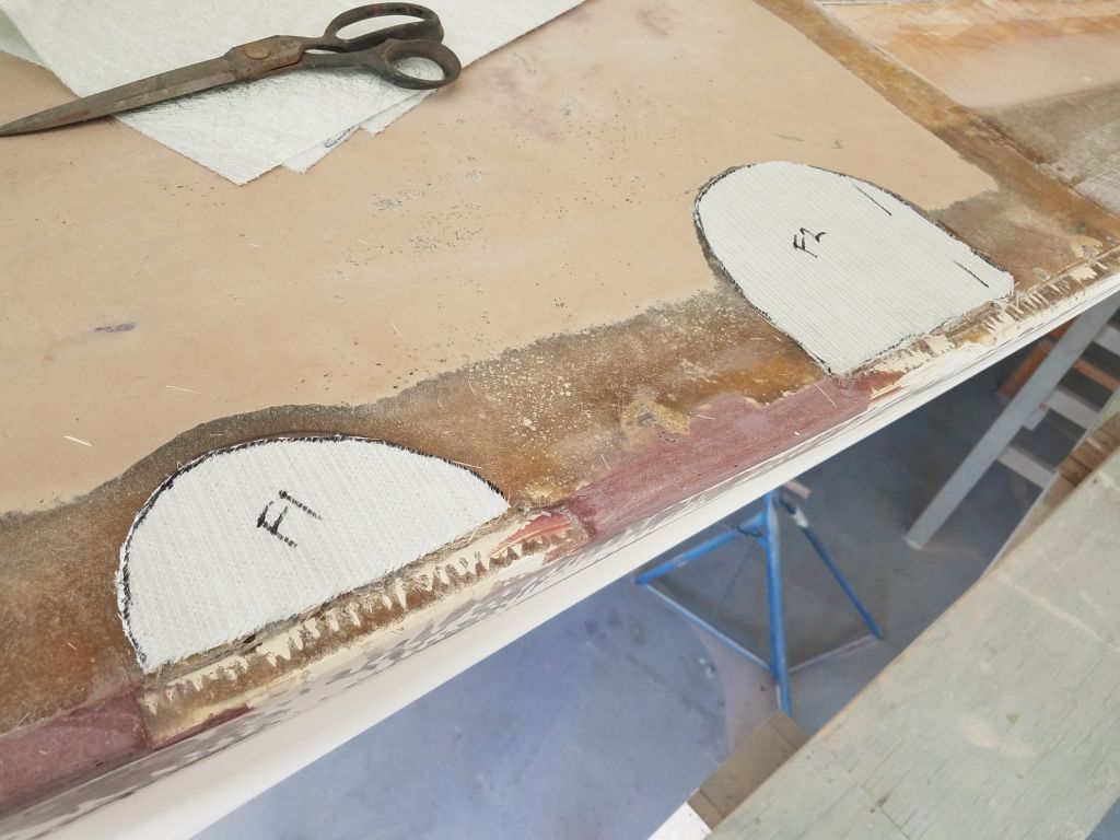
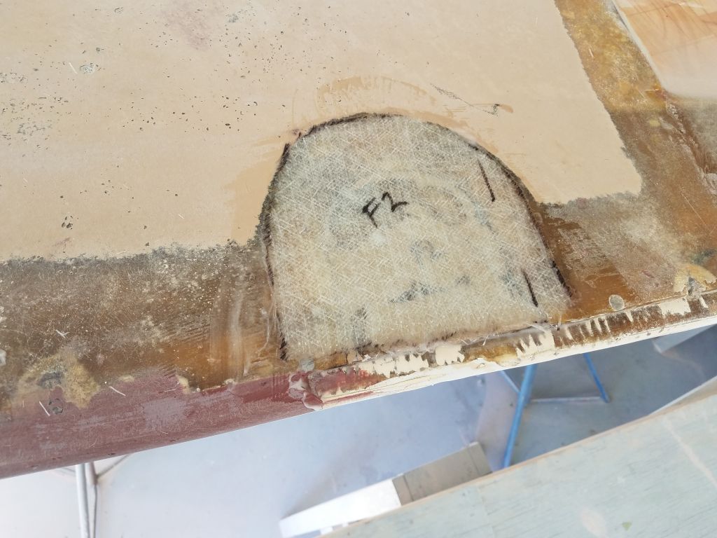
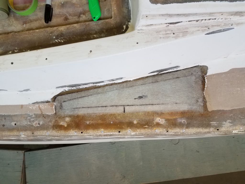
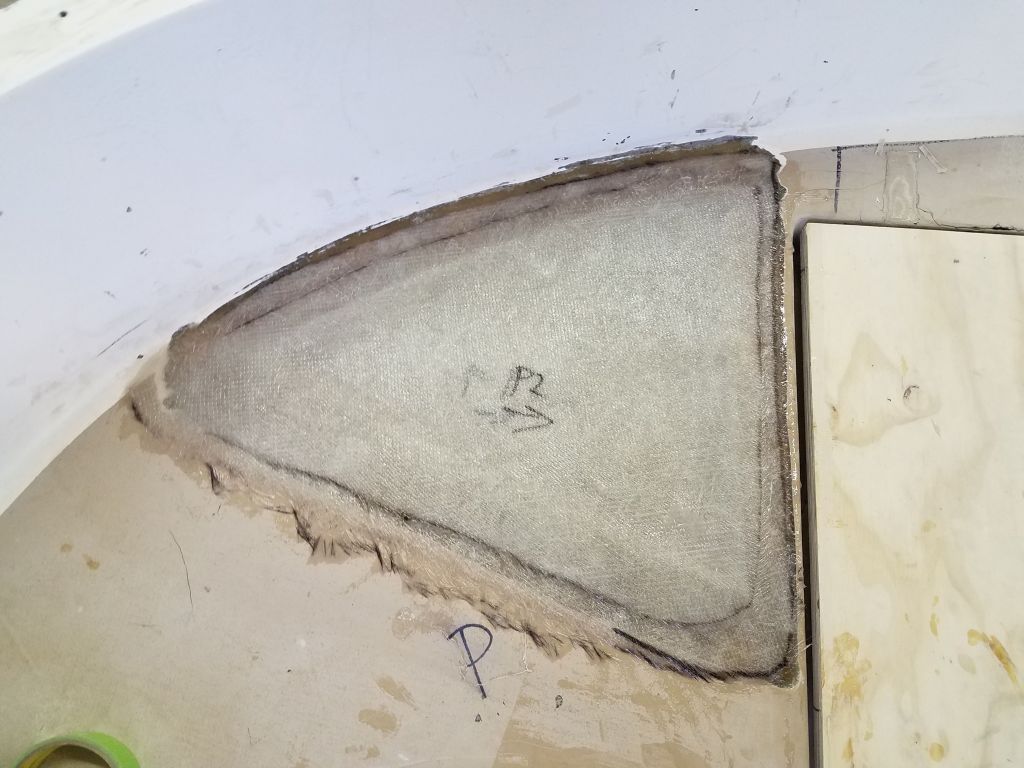
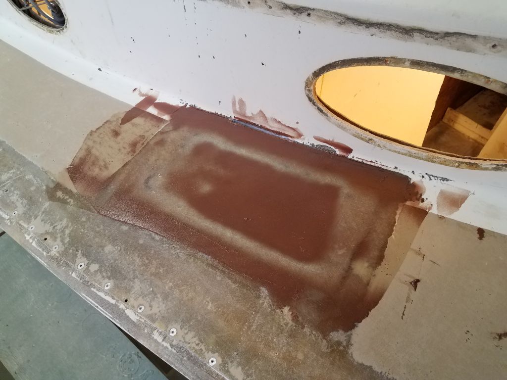
Earlier, near the port gunwale on the foredeck, I’d ground out a couple old and suspect repairs on the deck so I could add some new fiberglass. While I planned to incorporate these areas into the eventual hull/deck tabbing a little later, for now I wanted to add a layer of fiberglass to begin the buildup and allow me to fill the edge of the deck through these sections as well.


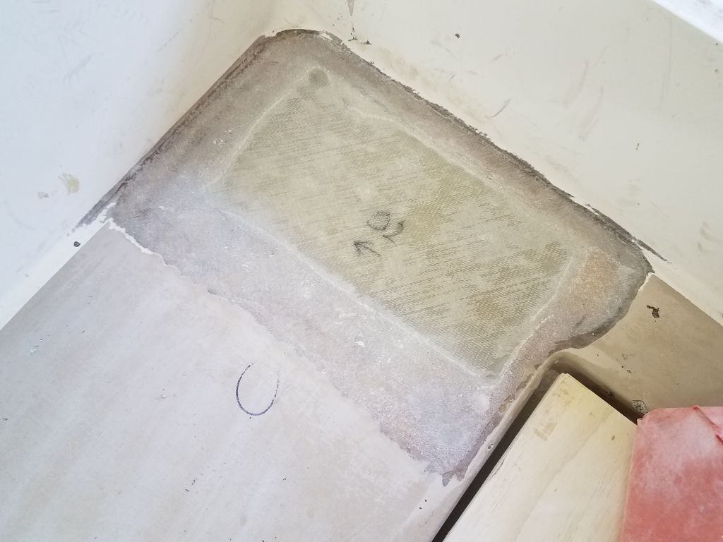
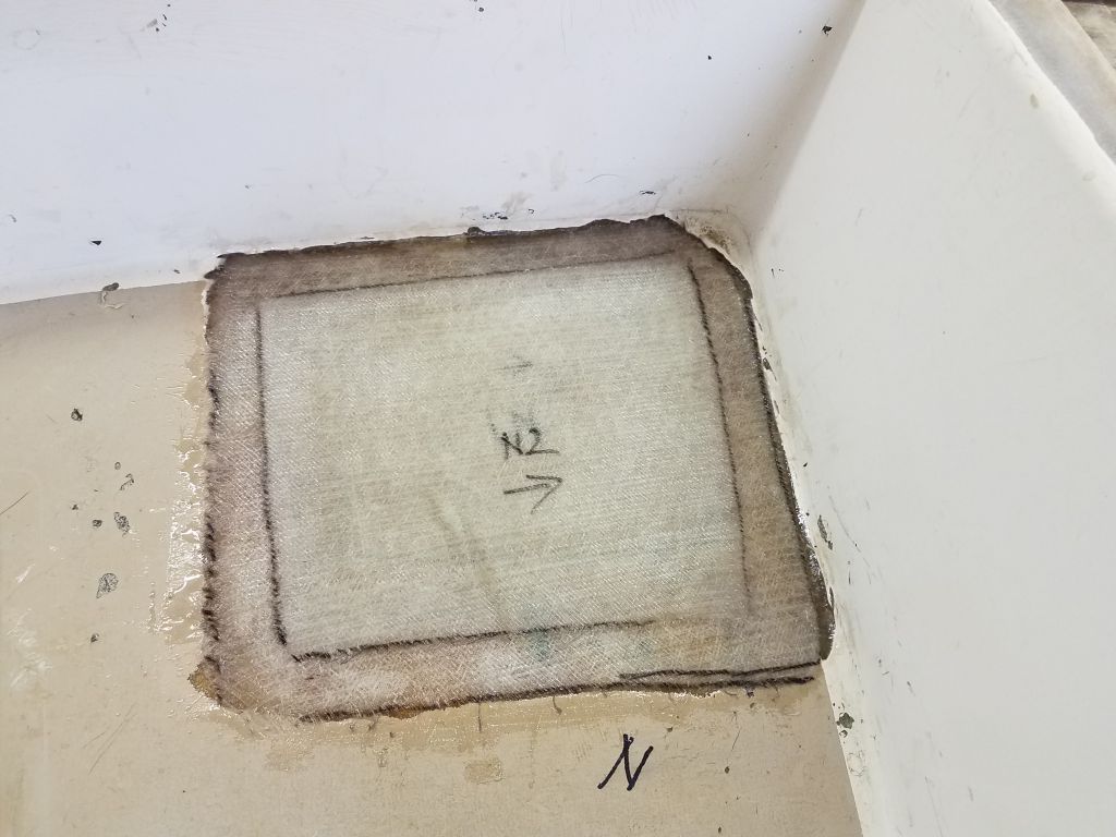
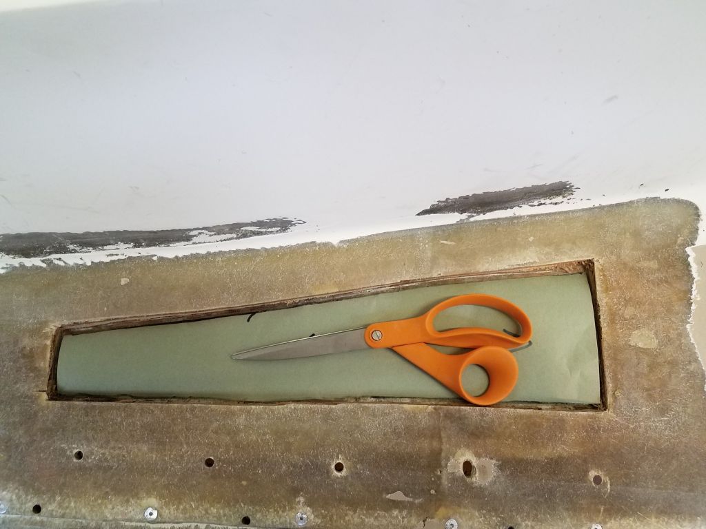
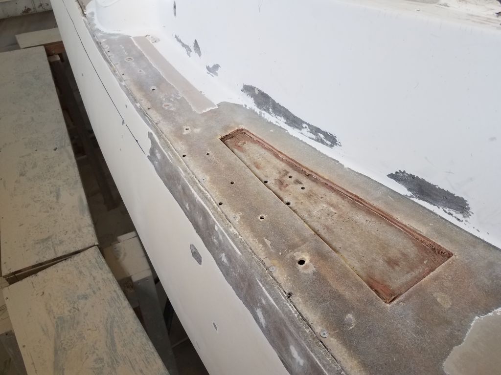
At the aftermost end of the port sidedeck was a small area outboard of the cockpit where I’d removed core earlier. I’d decided long before to fill this tiny section with solid fiberglass, so with the core underway I went ahead and installed 8 layers of 1708 in the small space, spread out over two applications during the morning and afternoon.

Next, I applied epoxy fairing compound to the newly-glassed bridgedeck and coachroof, the first coat to begin to fill the weave of the cloth as necessary. I also applied fairing compound to the last cockpit patch on the sole, plus the other areas that had only received one coat of fairing filler so far.

Most of the starboard hull/deck edge required a second round of epoxy filler, which I did now. I used up extra in areas on the port side where I’d not previously filled, such as around the small repairs on the foredeck.


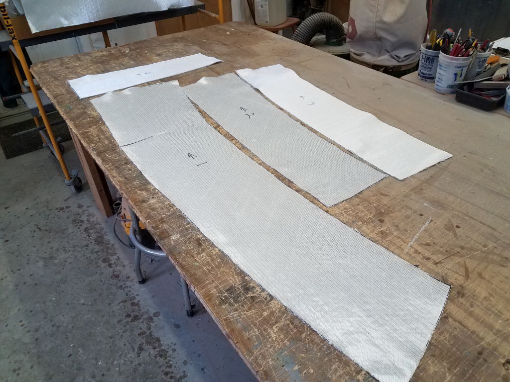
To finish up the day and prepare for next time, I cut three layers of 1708 fiberglass for the port sidedeck.
Total time billed on this job today: 8.25 hours
0600 Weather Observation: 26°, clear. Forecast for the day: Sunny, 60°
Friday
After removing the core weights and other preparations, I lightly sanded the newly-cored areas to remove any epoxy ridges or overspill, and sanded the new fiberglass top skins on the smaller repairs I’d made earlier. I’d also applied some filler to the small depression in the bottom skin near the forward end of the port sidedeck, and lightly sanded that as well.

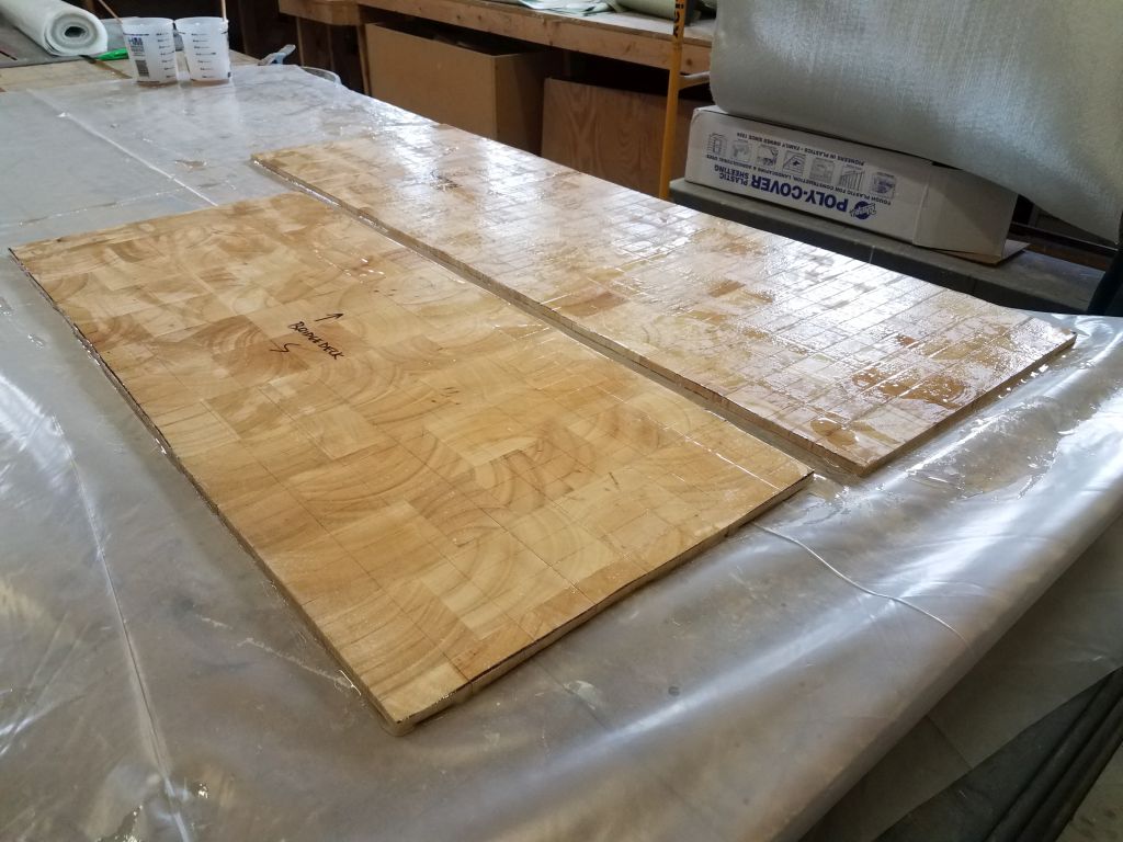
In my usual way, I made paper patterns for the fiberglass needed for the bridgedeck and coachroof, and cut out two layers of 1708 fiberglass for each section.
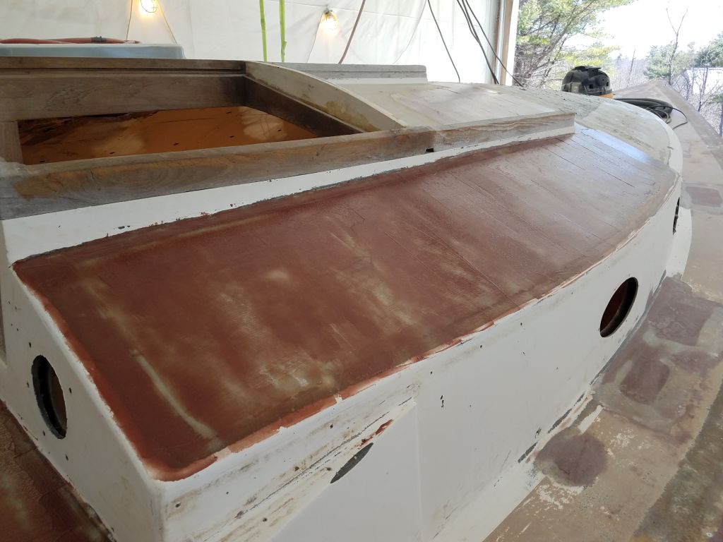
I filled any small gaps remaining around the new core with a thickened epoxy mixture, and after letting that sit while I cut out the new fiberglass, I laminated both areas with the two new layers.

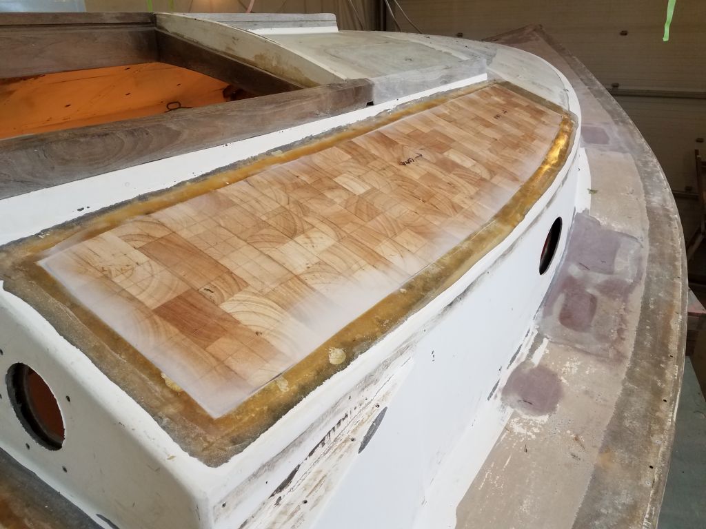

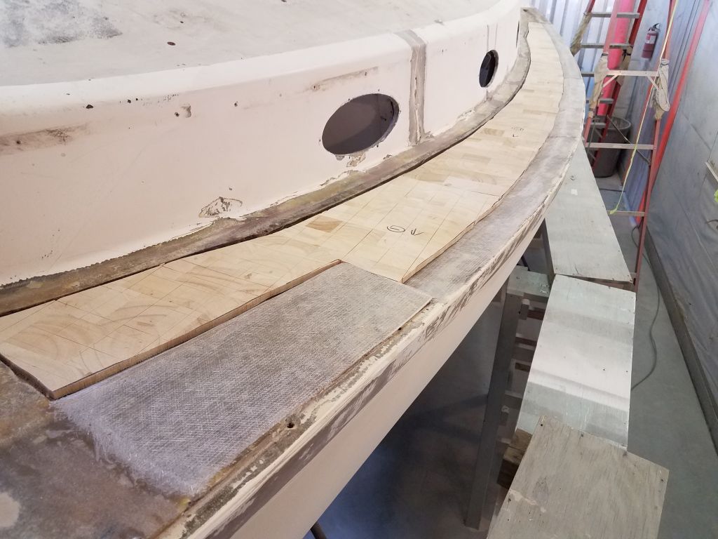
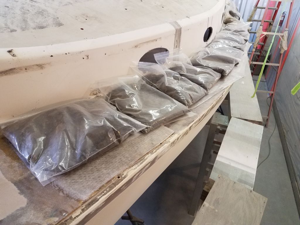
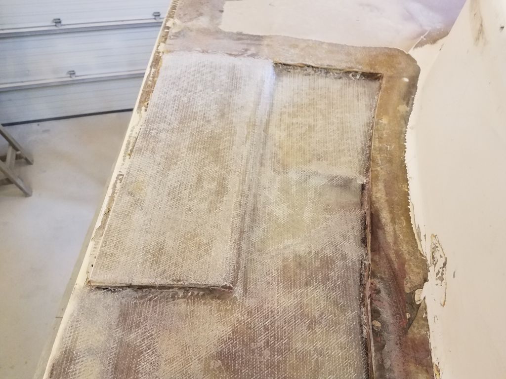
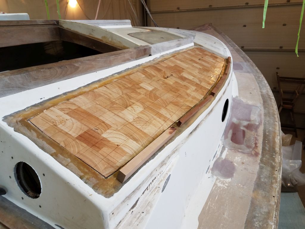
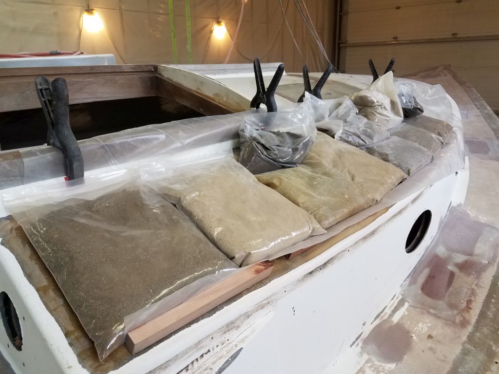
I dry fit the new core pieces on the port sidedeck, made a couple minor adjustments, and then installed the new core in thickened epoxy adhesive, weighing it all down securely.

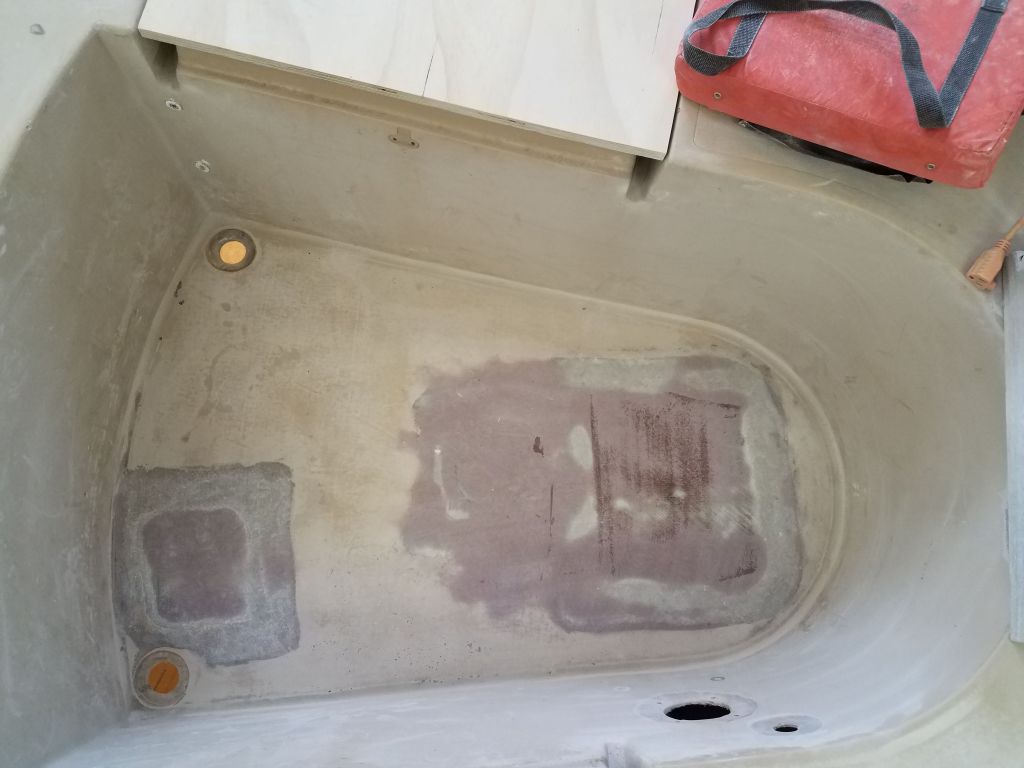
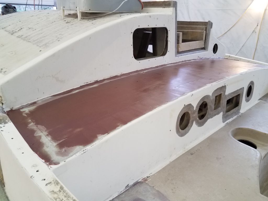
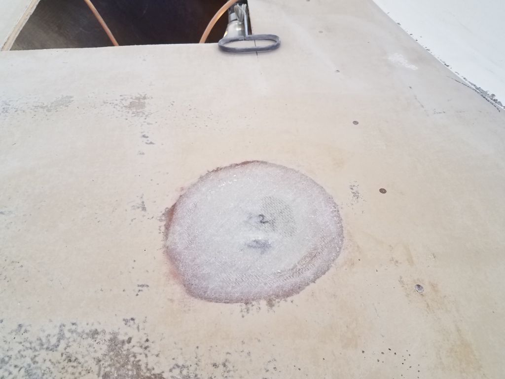
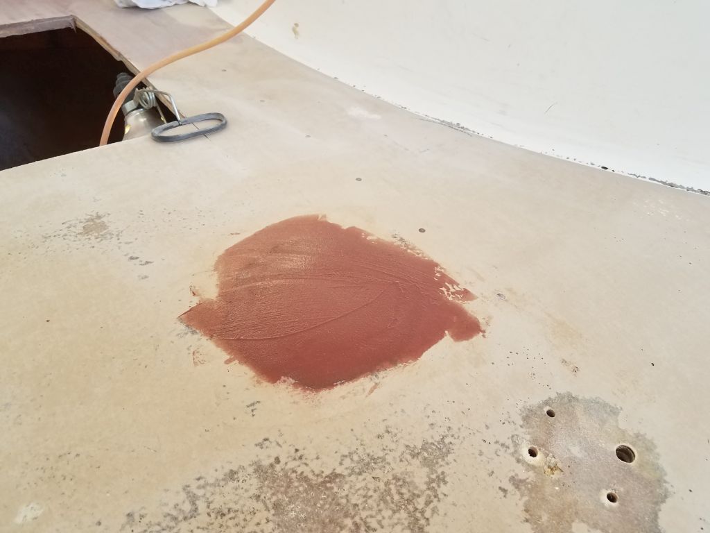
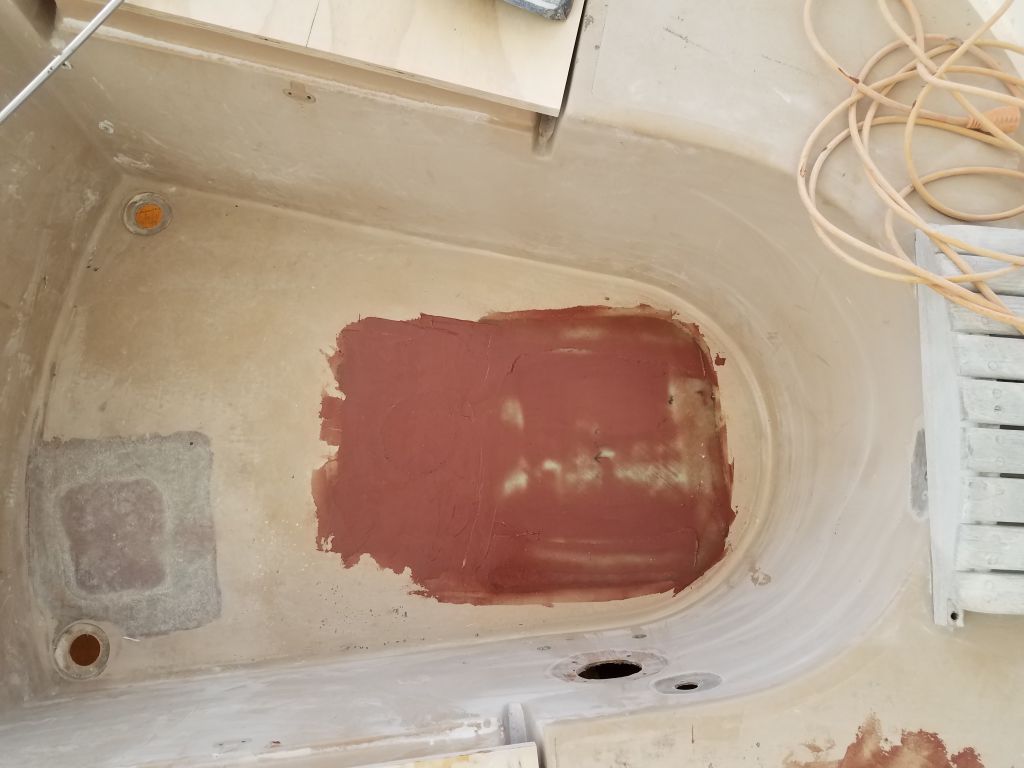
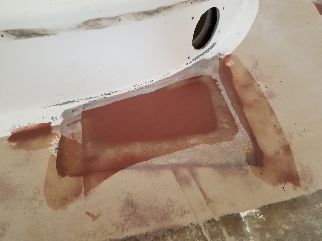
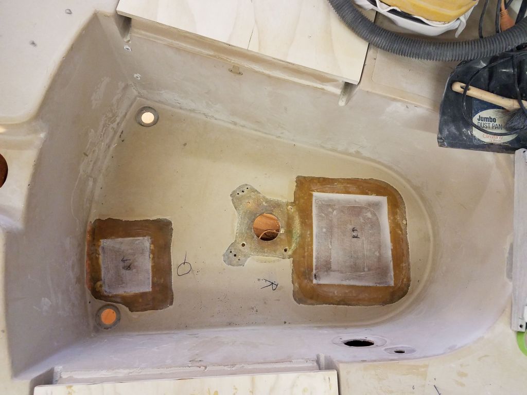
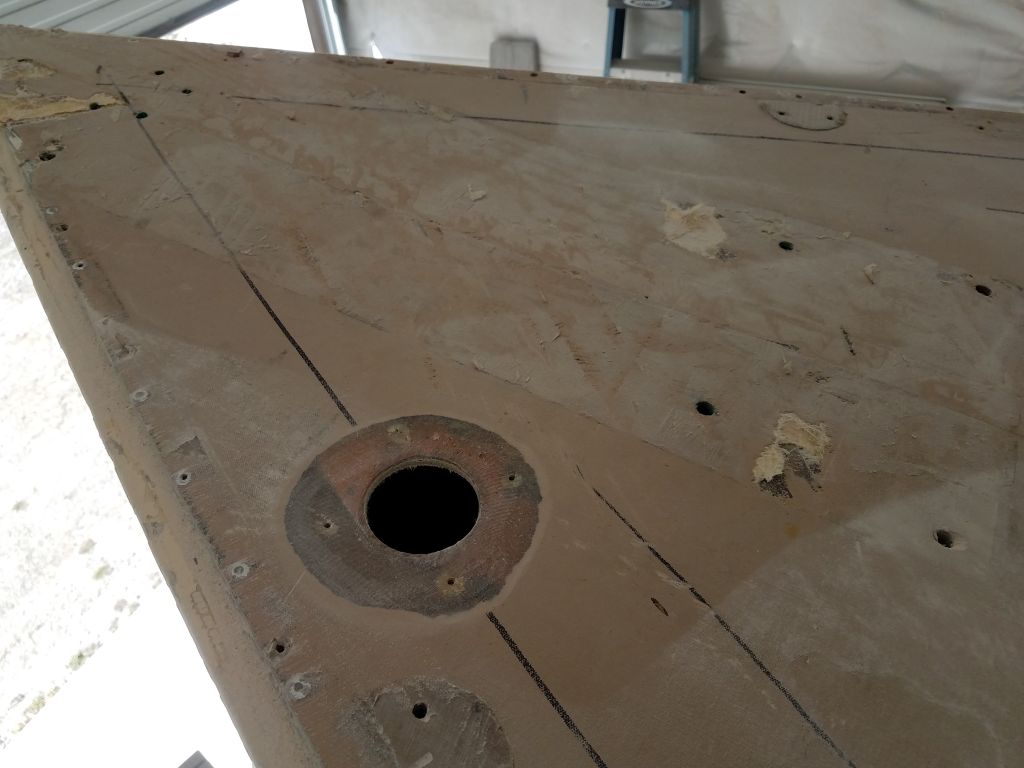
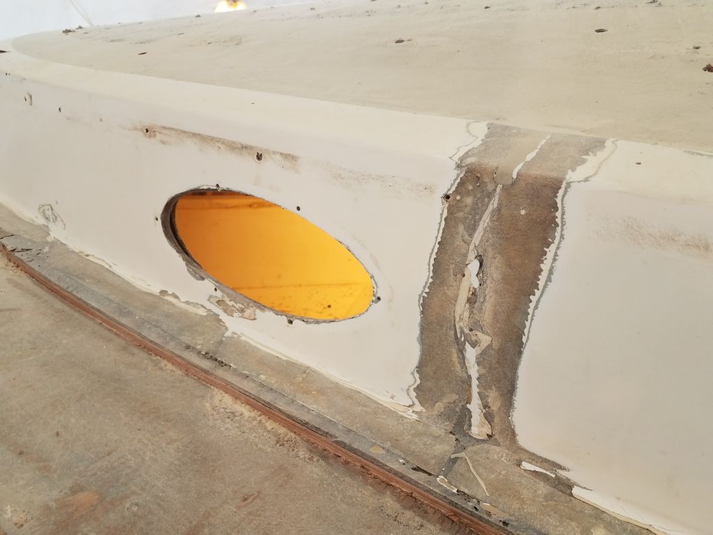
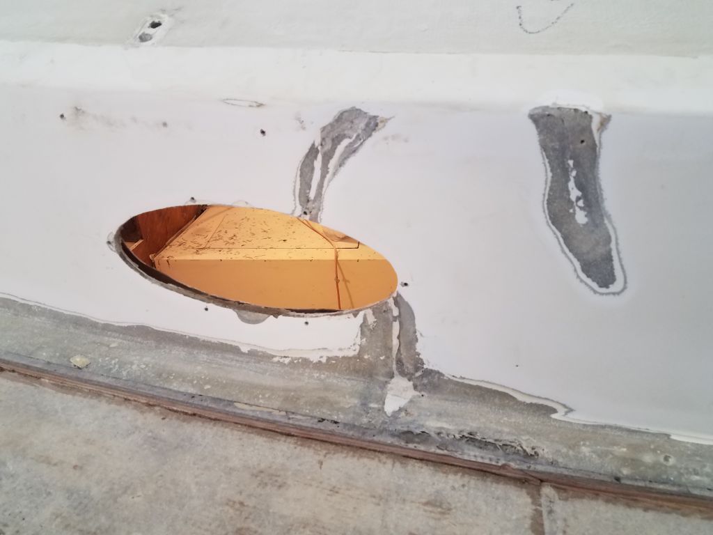
In the cockpit, I filled the large hole left over from the steering pedestal, then installed the two layers of fiberglass over the top of the whole area that I’d prepared earlier. I also filled and patched the old fuel tank fill hole on the poop deck. Later, once I’d shifted operations belowdecks, I’d complete these two patches from the underside.

Finally, picking up where I’d left off before, I finished up the initial filling of the hull-deck joint on the starboard side, and applied a second round of filler as needed to some of the previously-filled areas on the port side.
Total time billed on this job today: 7.5 hours
0600 Weather Observation: 34°, drizzle. Forecast for the day: Clouds, showers, maybe some sun, around 50°
Thursday
I began with my usual round of sanding over the various patches currently underway, including the port sidedeck, two small areas where I’d installed new core, and the first round of filler at the hull/deck joint where I’d applied it.


Next, I patterned and cut fiberglass for the small repairs on the coachroof and starboard sidedeck, and installed the two layers of new fiberglass in epoxy resin.

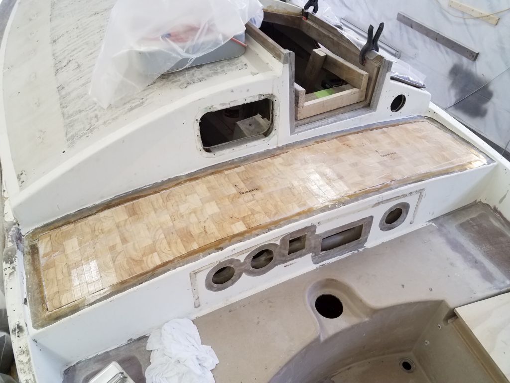
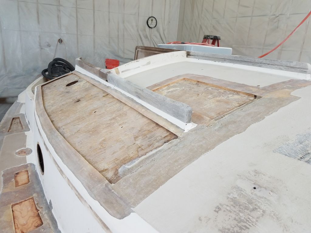
Earlier, I’d cut the new core material for the bridgedeck and the larger section of the coachroof, and now I dry-fit the pieces to check the fit.
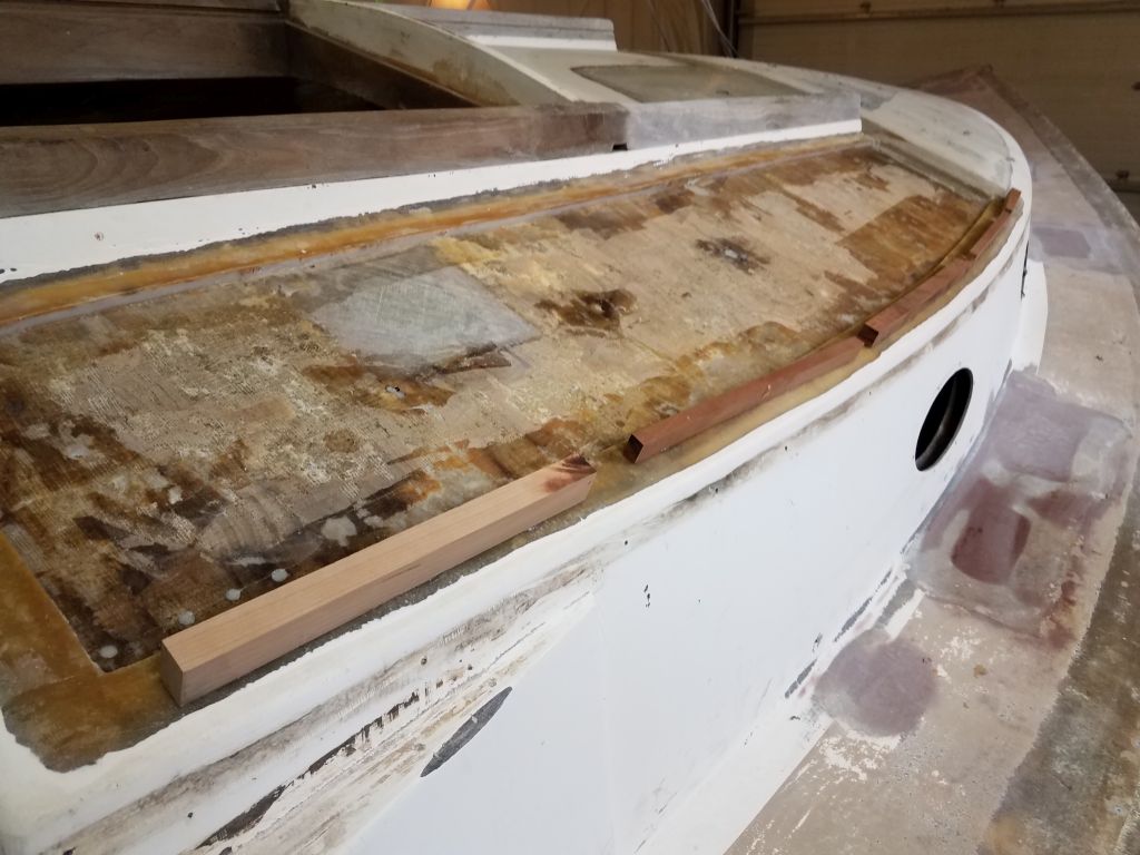
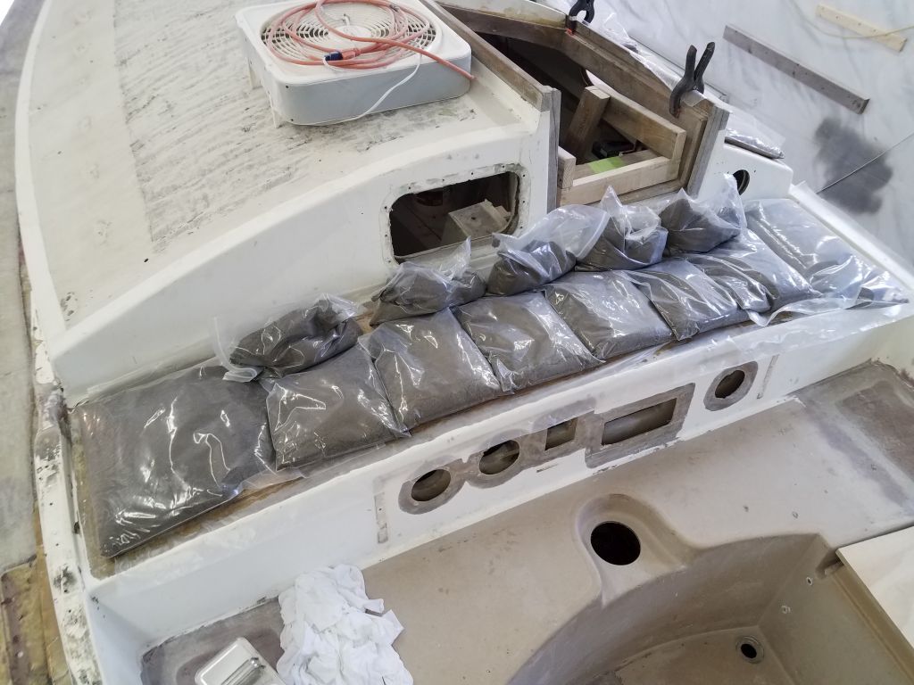
With the steep angle of the coachroof, I was concerned that the weights I used to press the core in place during installation would slip off, so to help hold things in place I hot-glued several scraps of wood to the edge of the deck.
With preparations complete, I wet out the new core and installed it in epoxy adhesive, weighing it down securely.

I repeated the process with the bridgedeck core.
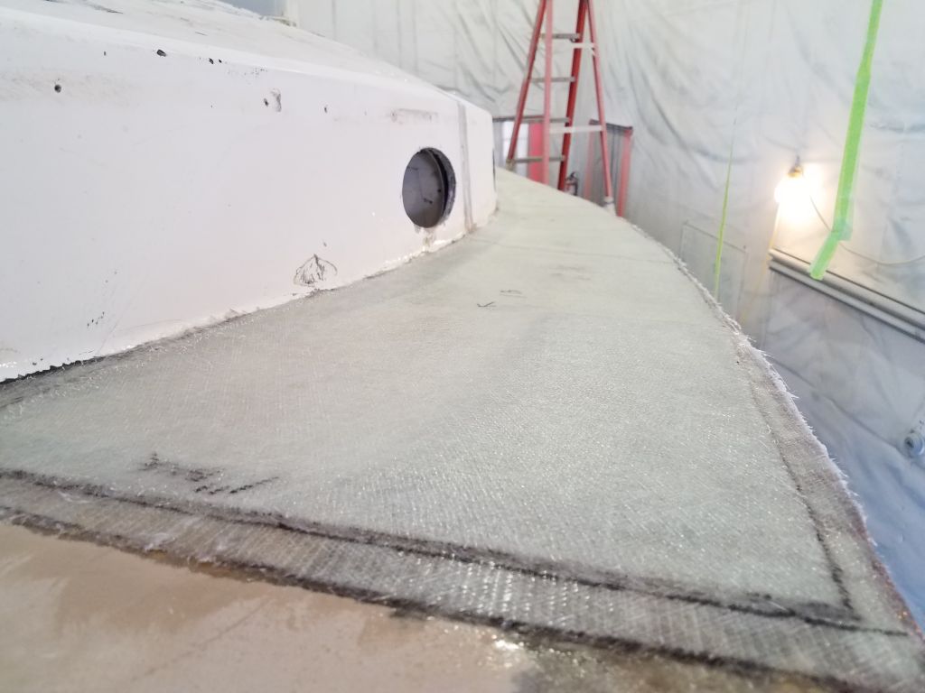
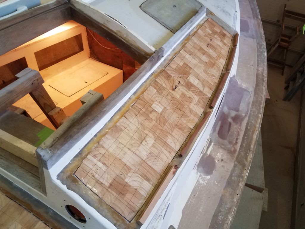
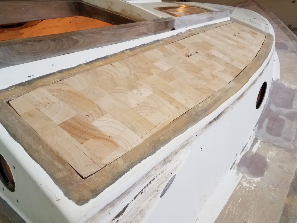
On the port sidedeck, I laid out the patterns I’d used for the first layer of fiberglass, then marked the outer edge where I wanted the new core to end, about 3-1/2″ in from the edge of the hull. Then, I cut the new core to fit, bringing me to the end of the day. I’d be ready to install this next time.

Total time billed on this job today: 7.5 hours
0600 Weather Observation: 36°, mostly cloudy. Forecast for the day: Mainly cloudy, 49°
Wednesday
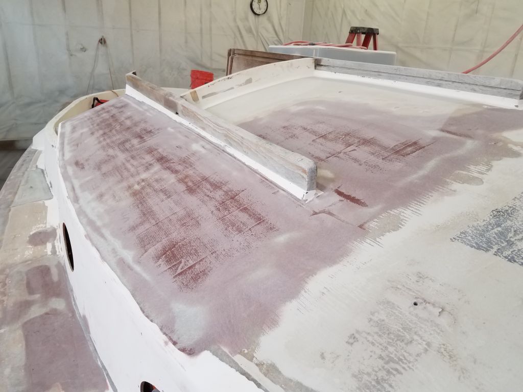
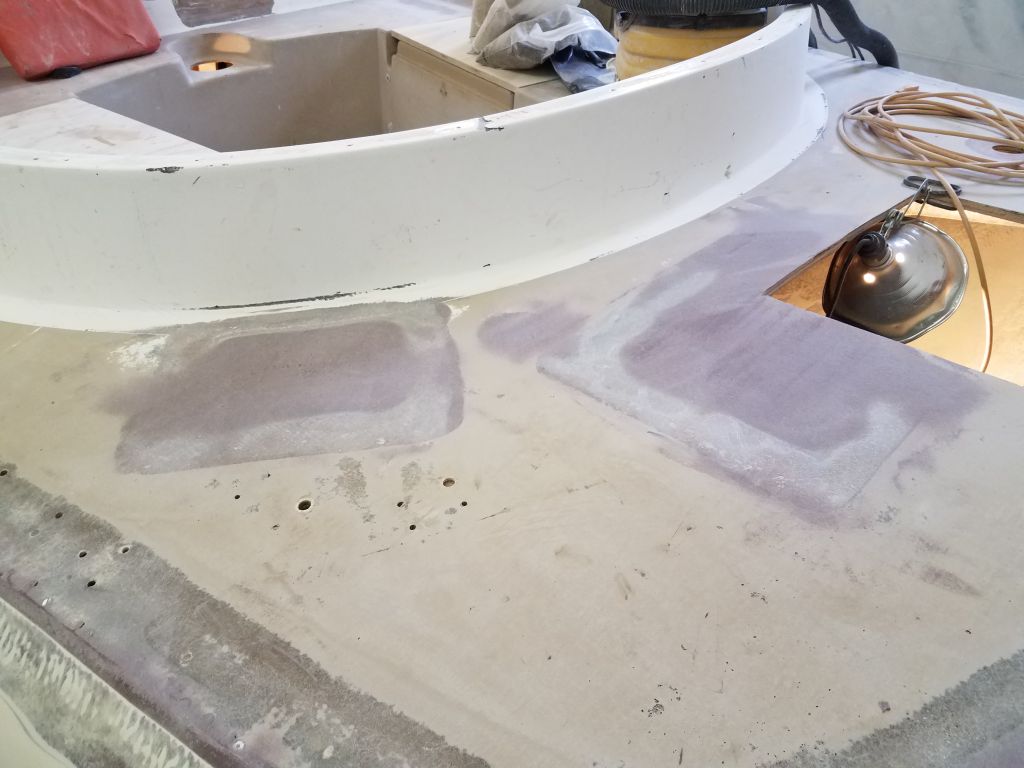
I began the day’s work with the sander, smoothing the new fiberglass in the cockpit patches and the fairing compound I’d applied on the main decks and port sidedeck.
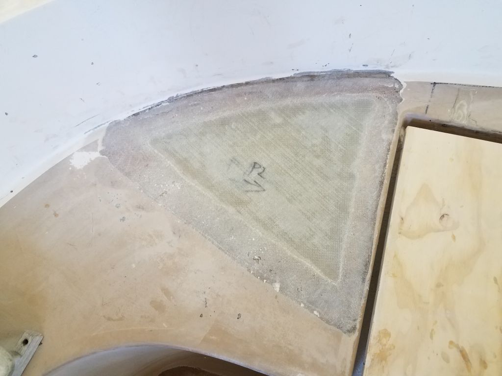


After I cleaned up, I used my patterns to cut new core for the small area on the coachroof and the small section of the starboard sidedeck. After final preparations to these areas, I installed the new core in epoxy adhesive, weighting it down securely.

Meanwhile, I cut the new core for the large section of the coachroof and for the bridgedeck, using the patterns I’d made earlier.

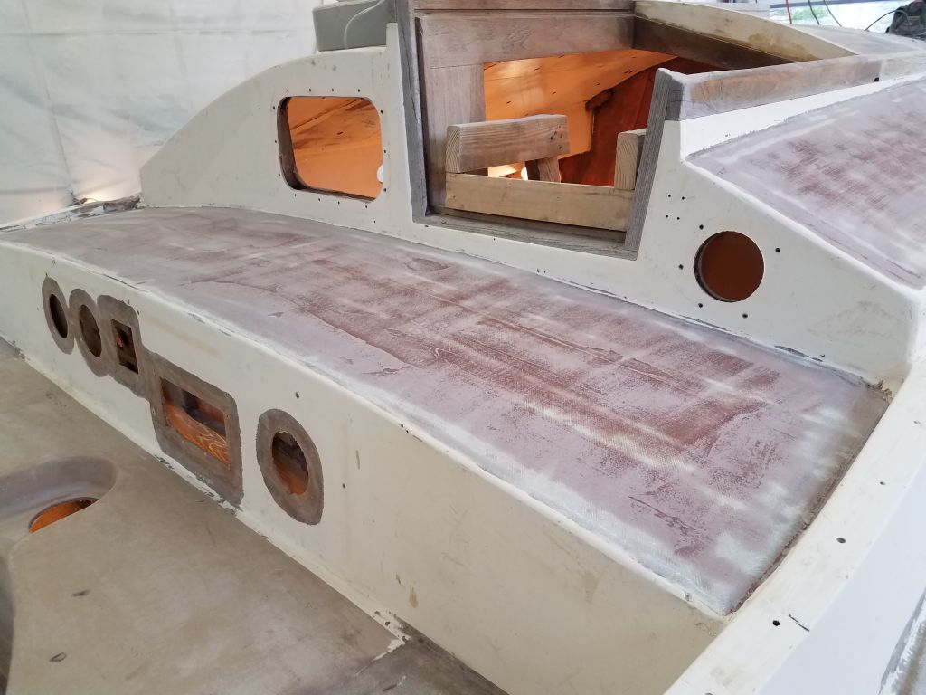
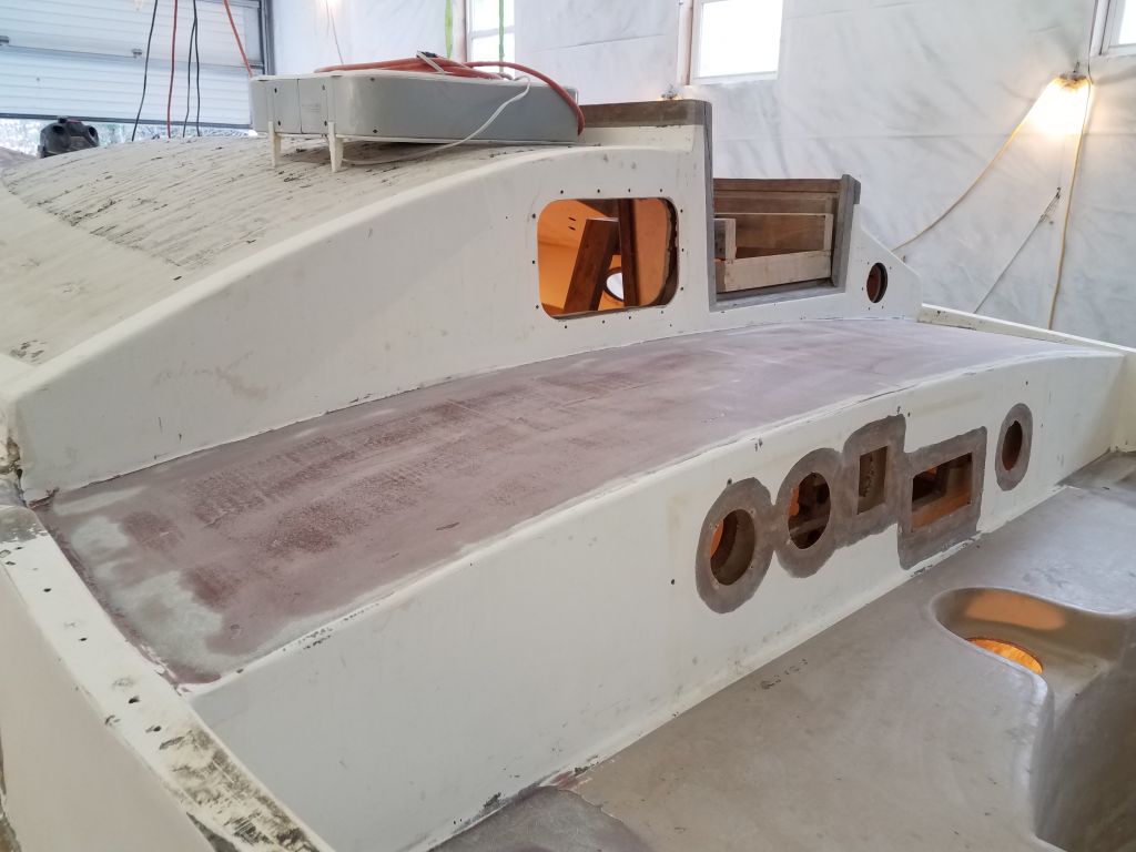
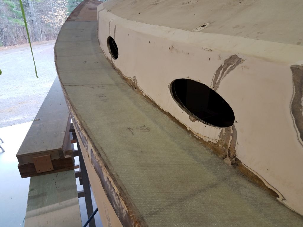
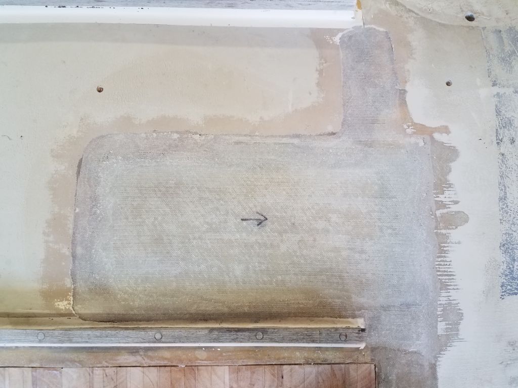
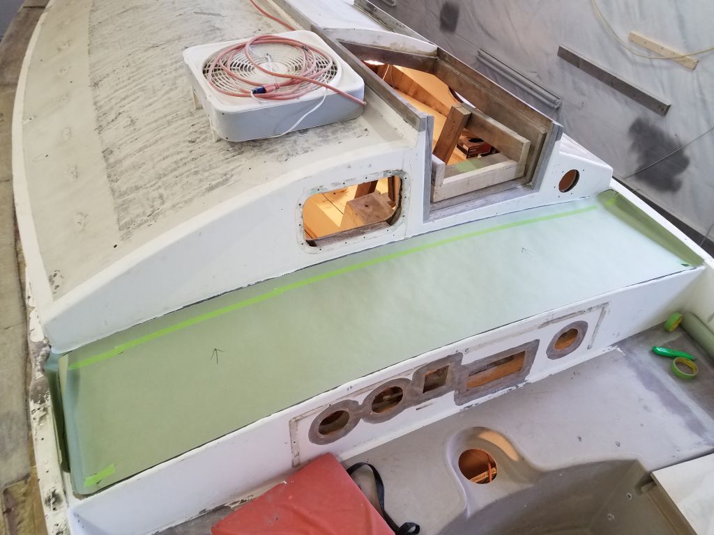
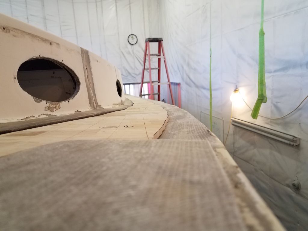
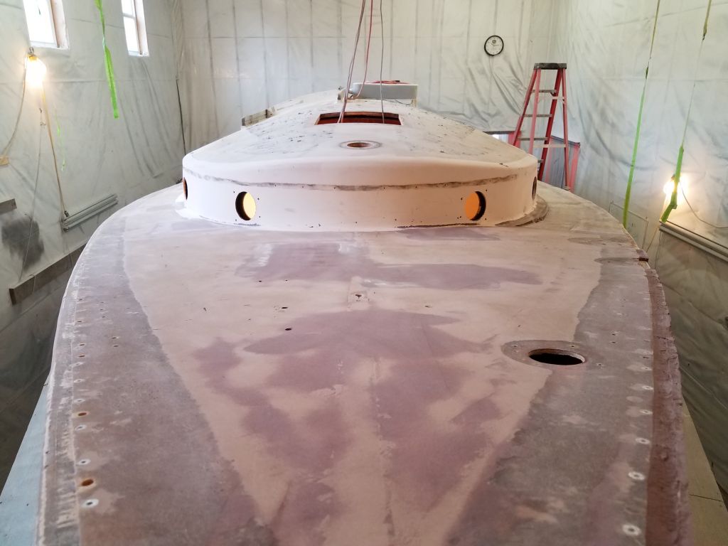
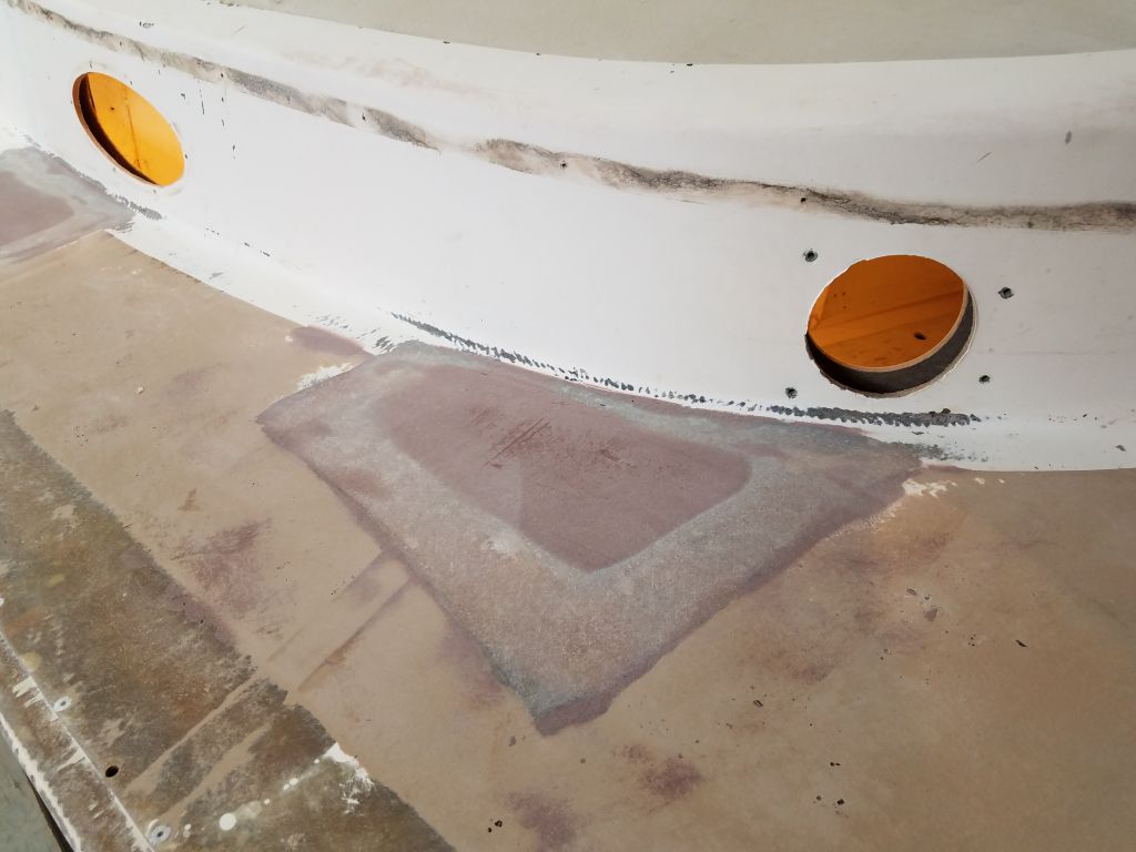
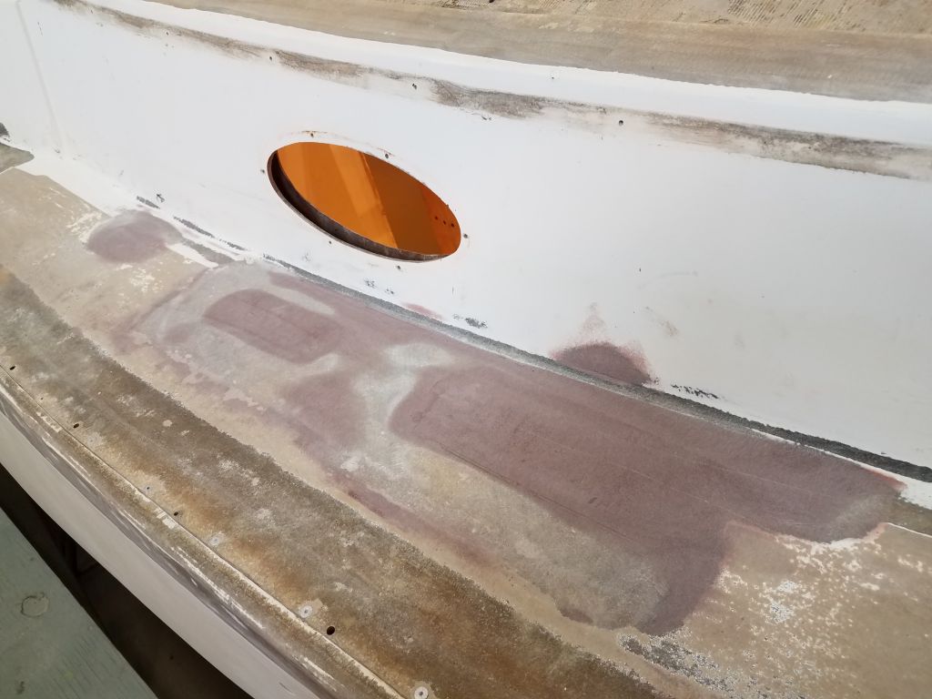
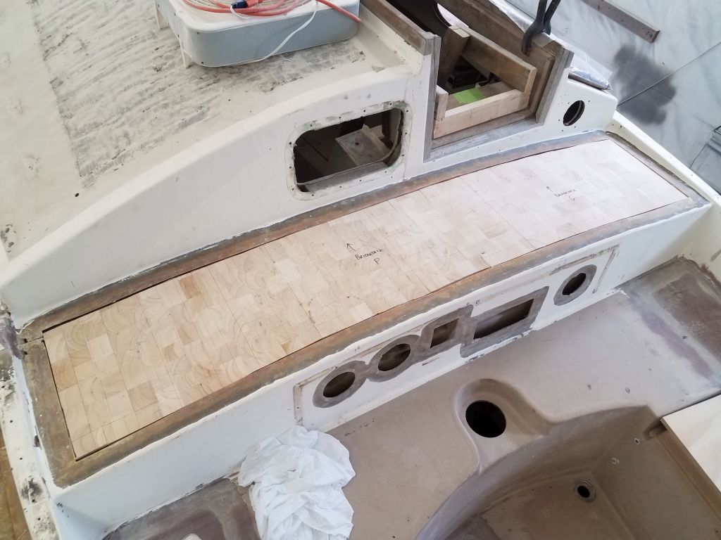
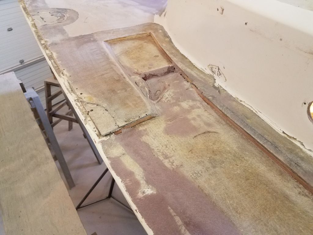
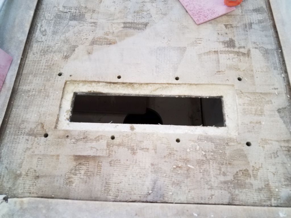
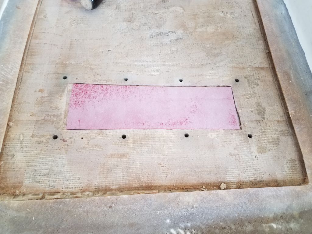
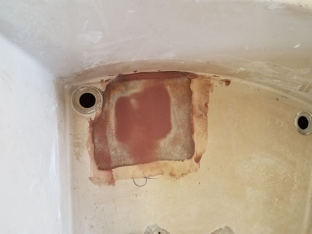
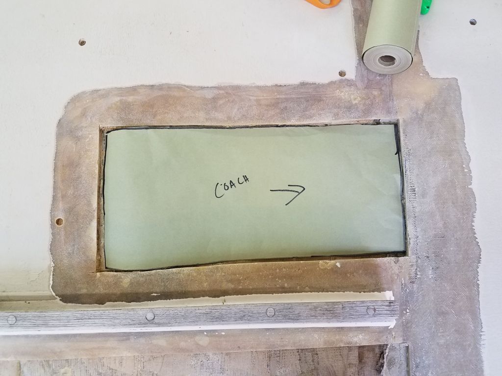
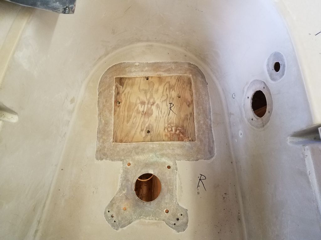
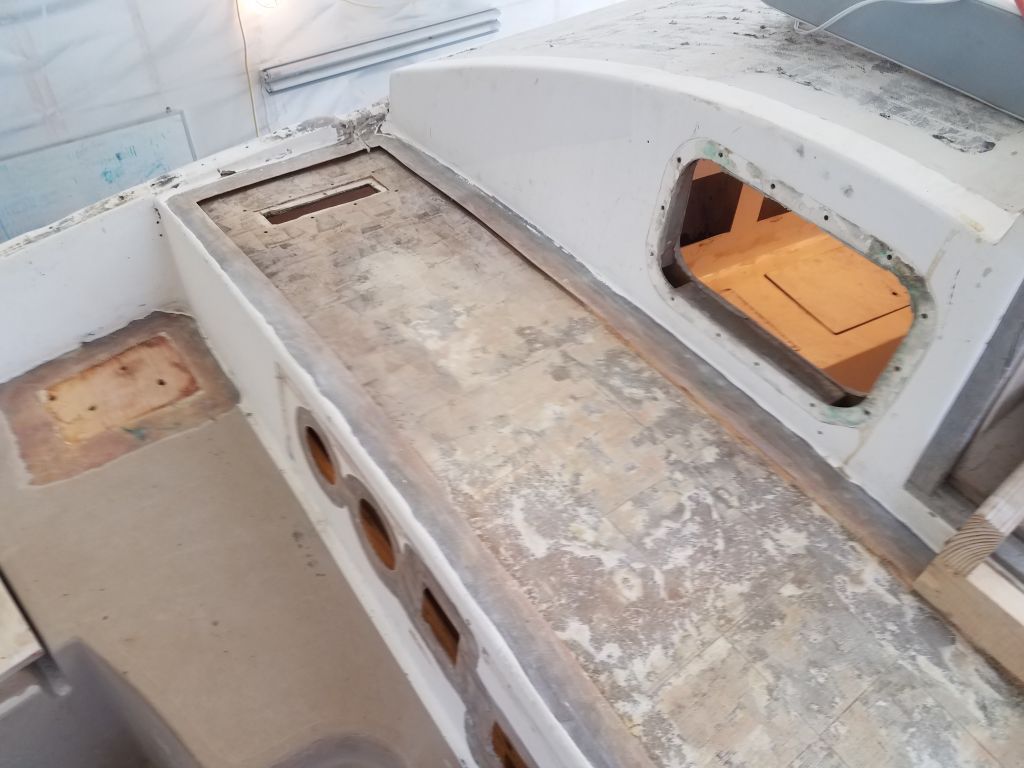
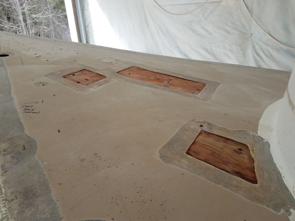
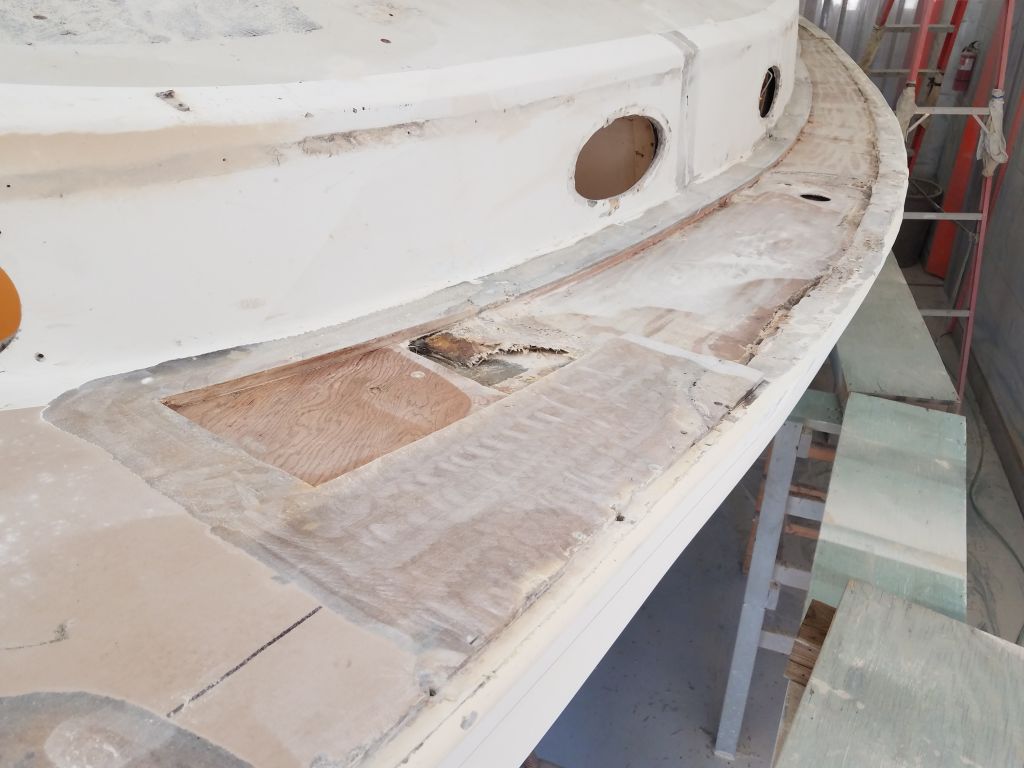
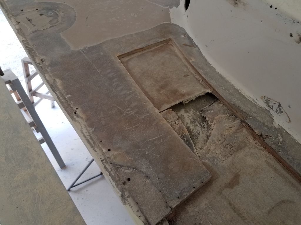
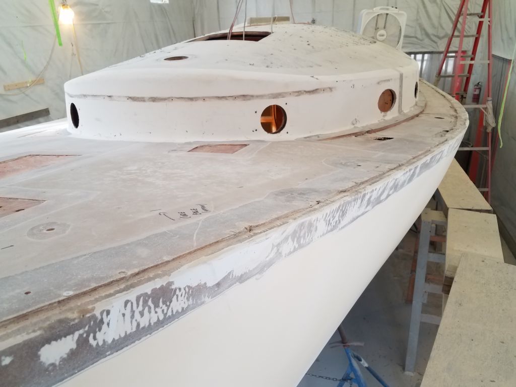
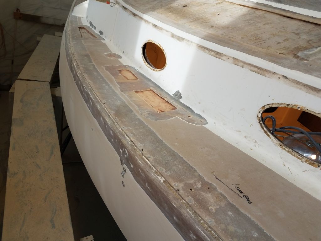
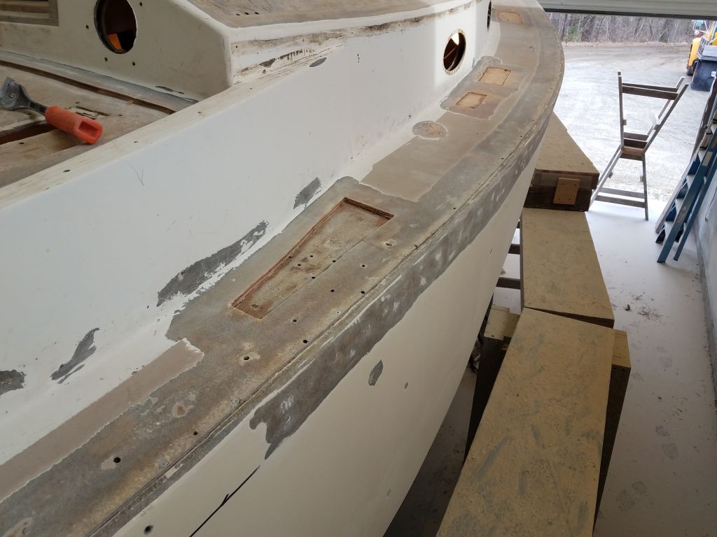
We planned to eliminate the deck prisms from the bridgedeck, and before I could install new core here I needed to patch the holes from above. This was a simple task since there was a nice flange beneath the existing rectangular openings, so all I had to do was clean up the faying surface a bit and install some 1/8″ thick prefab fiberglass sheeting over the openings with epoxy adhesive. Sometime later in the project, I’d patch the openings from inside, where the remainder of the finish work would be required.


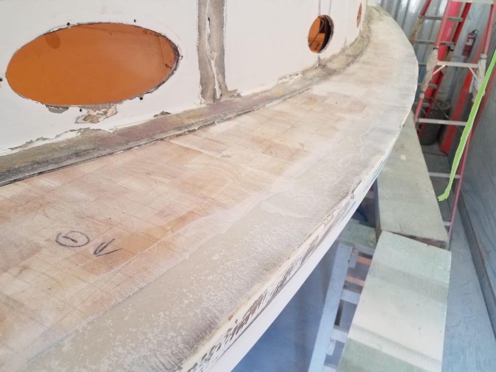
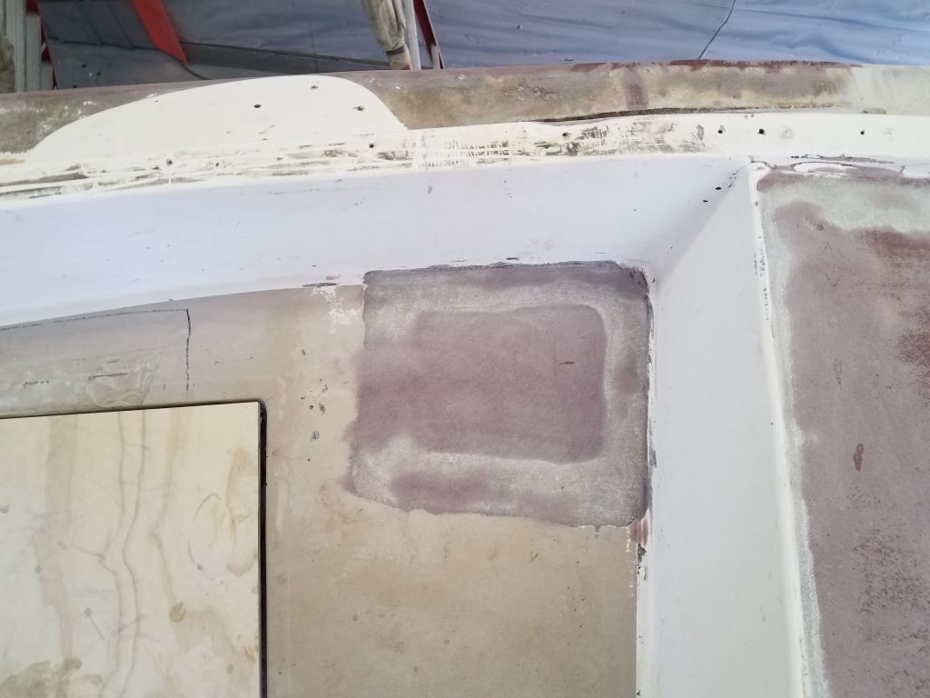
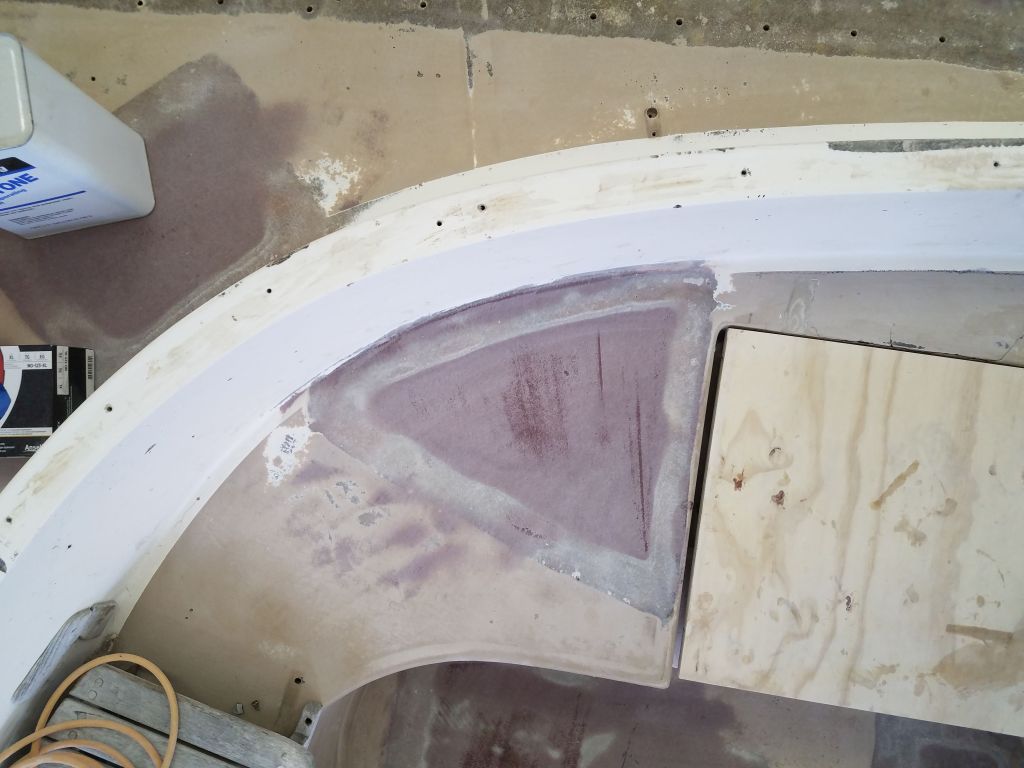
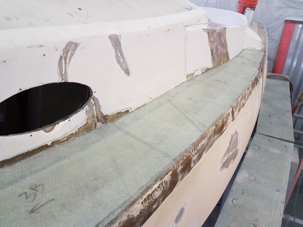
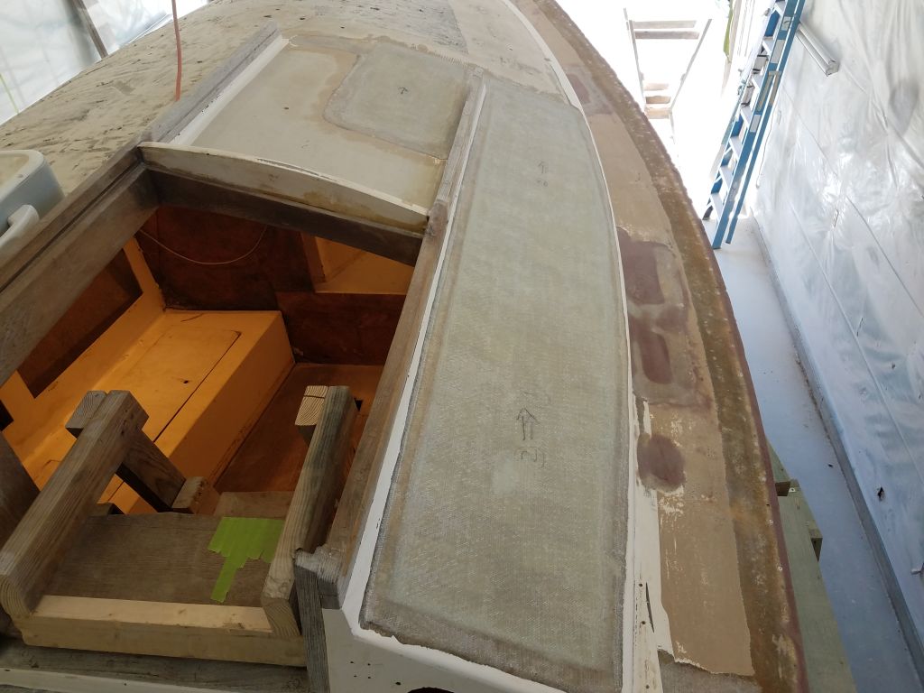
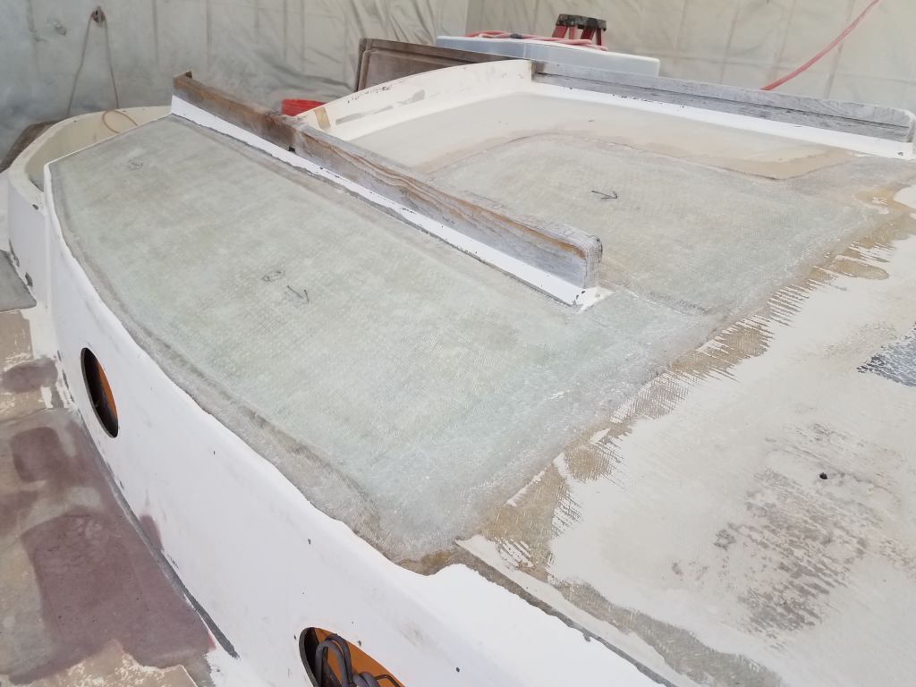
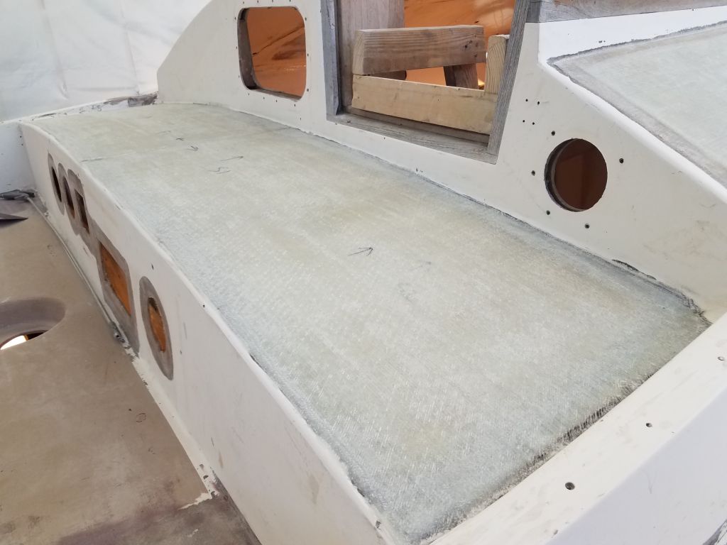
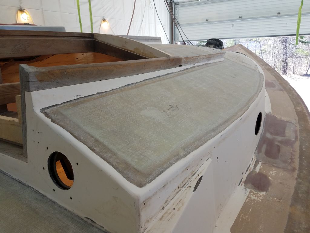
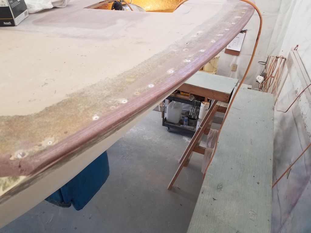
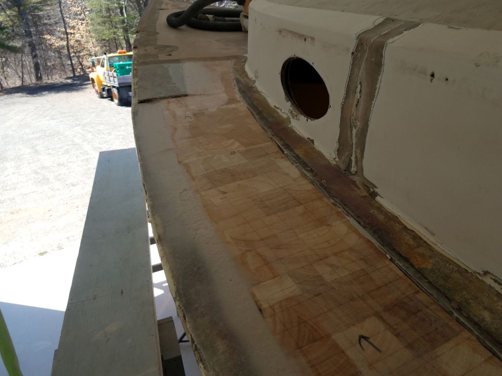
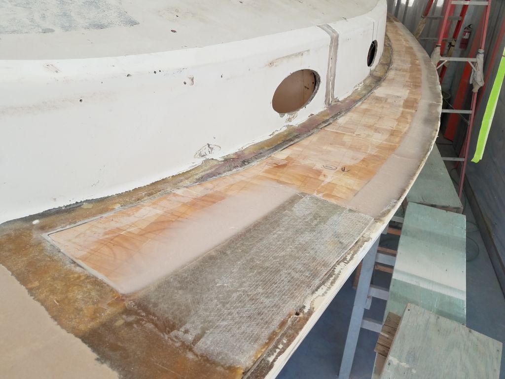
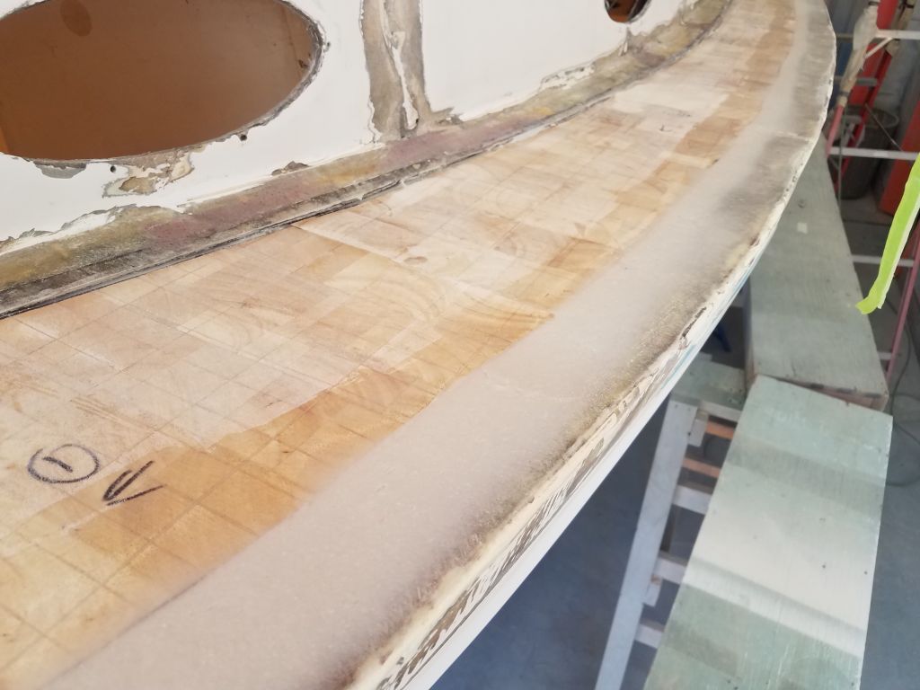
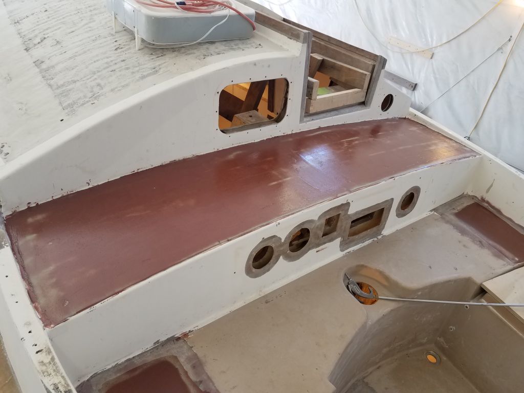
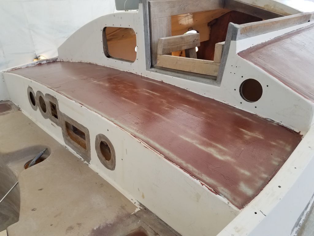
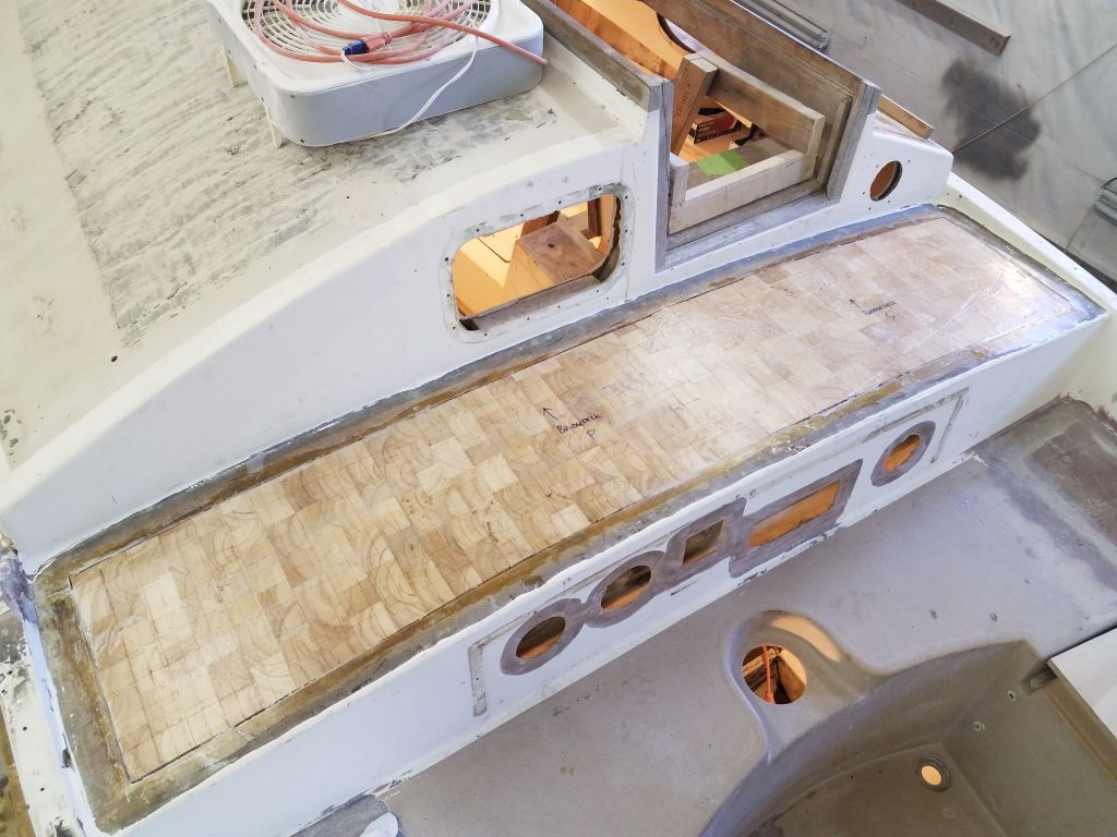
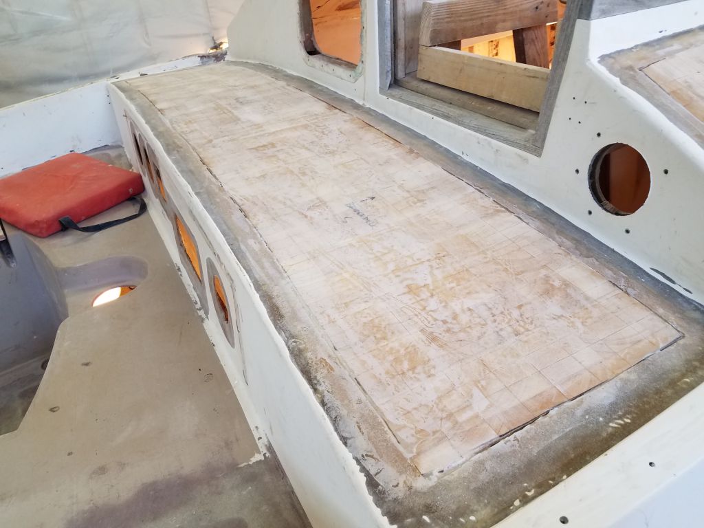
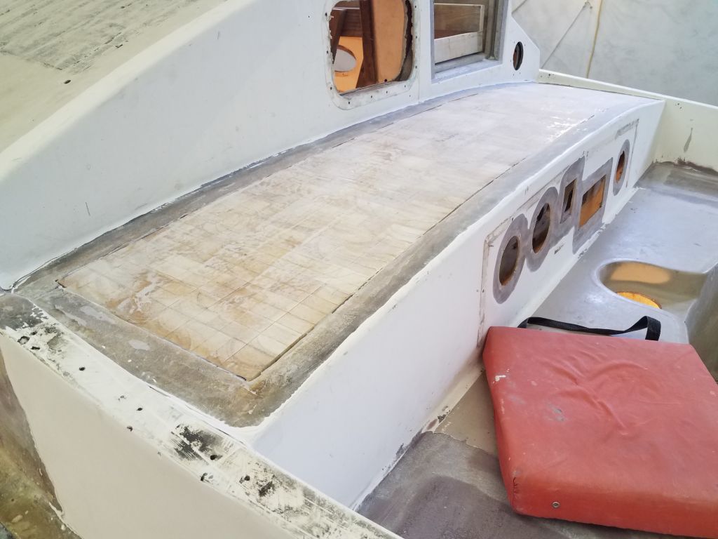
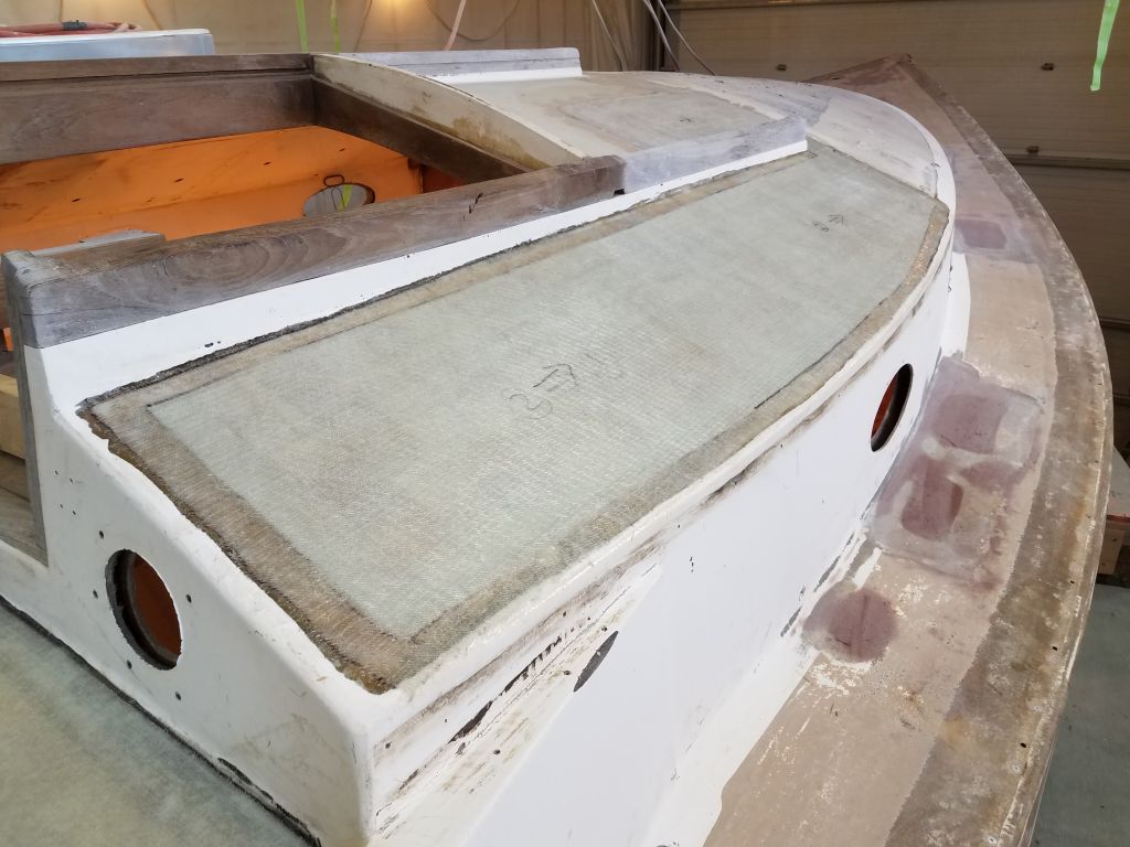
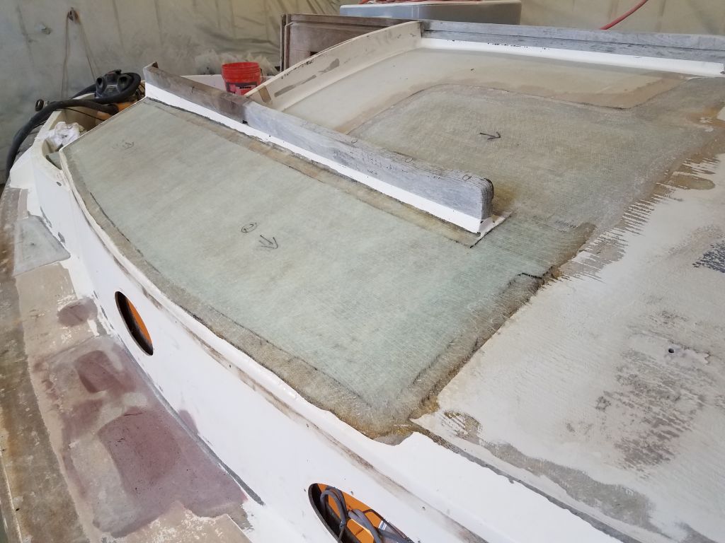
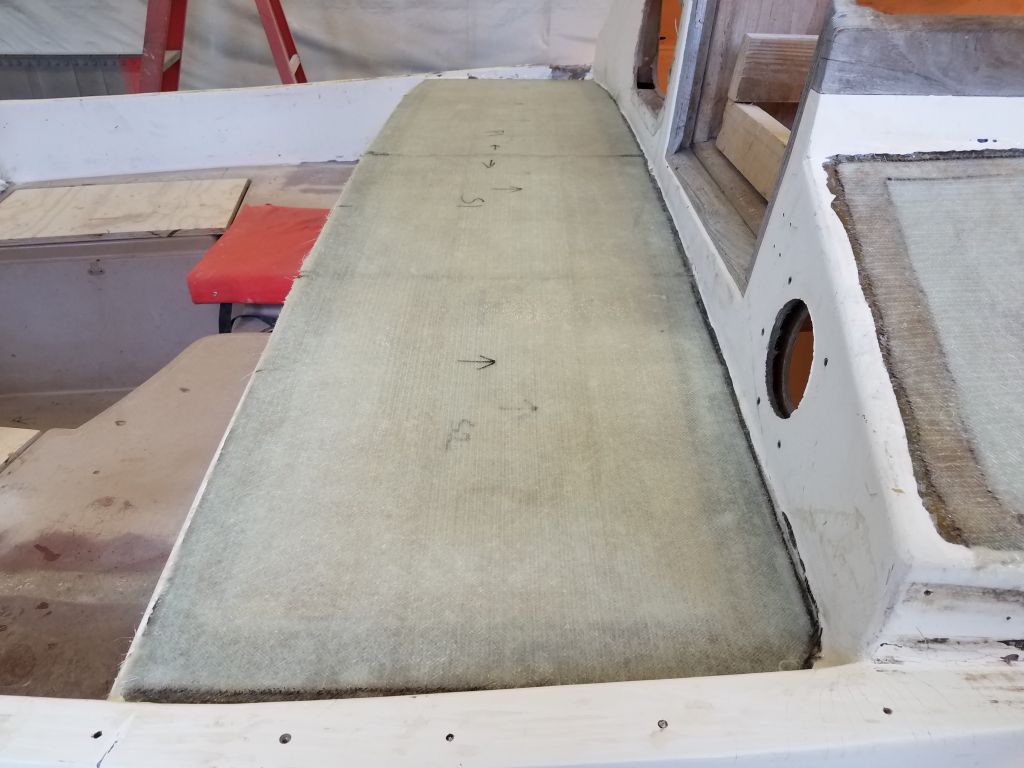
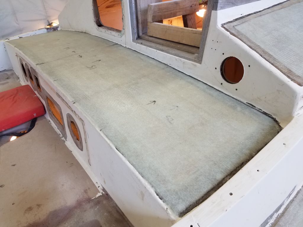
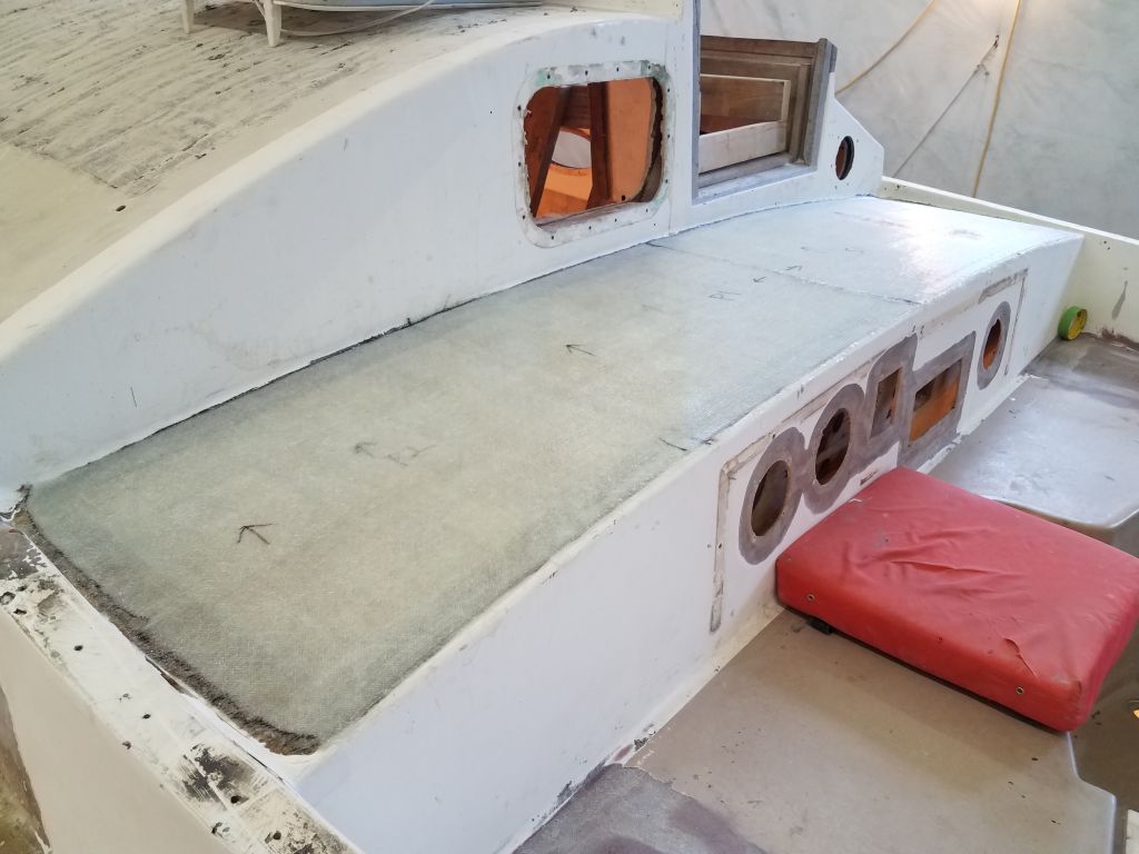
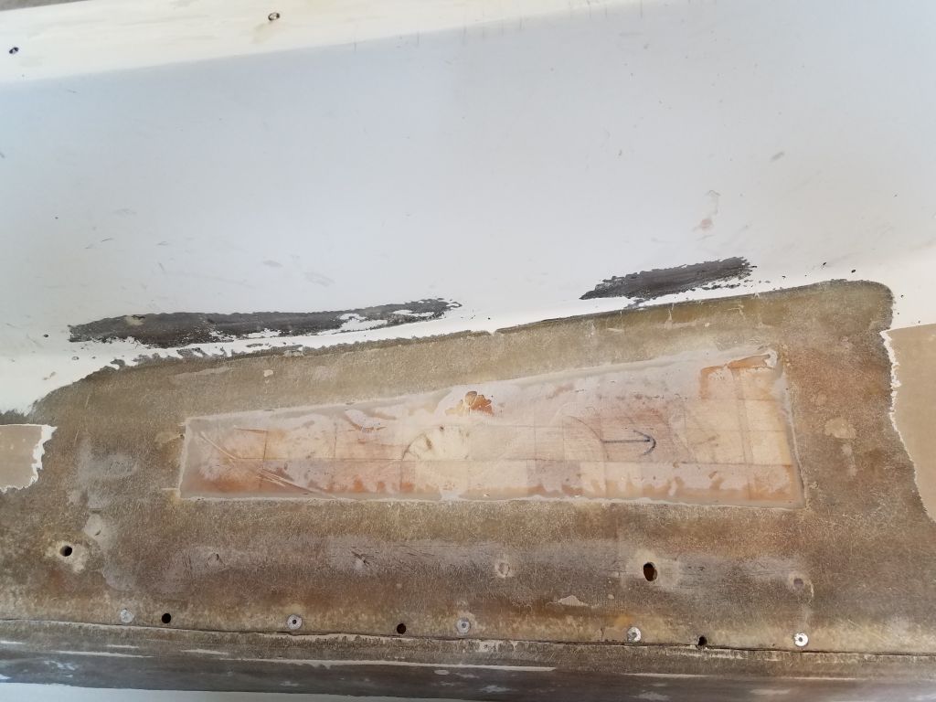
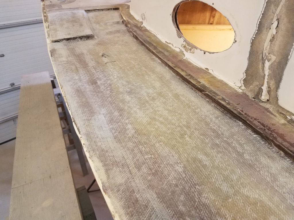
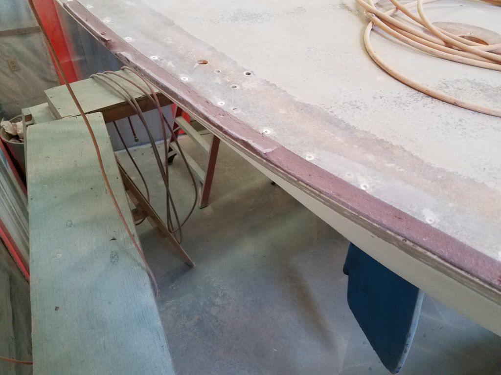
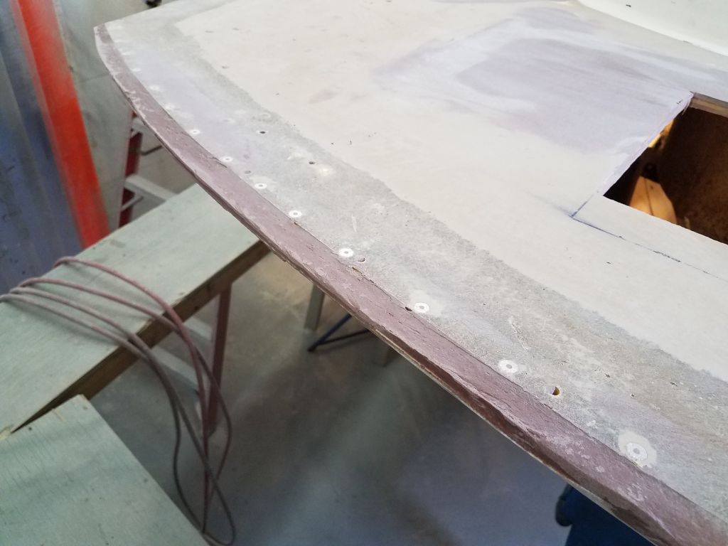
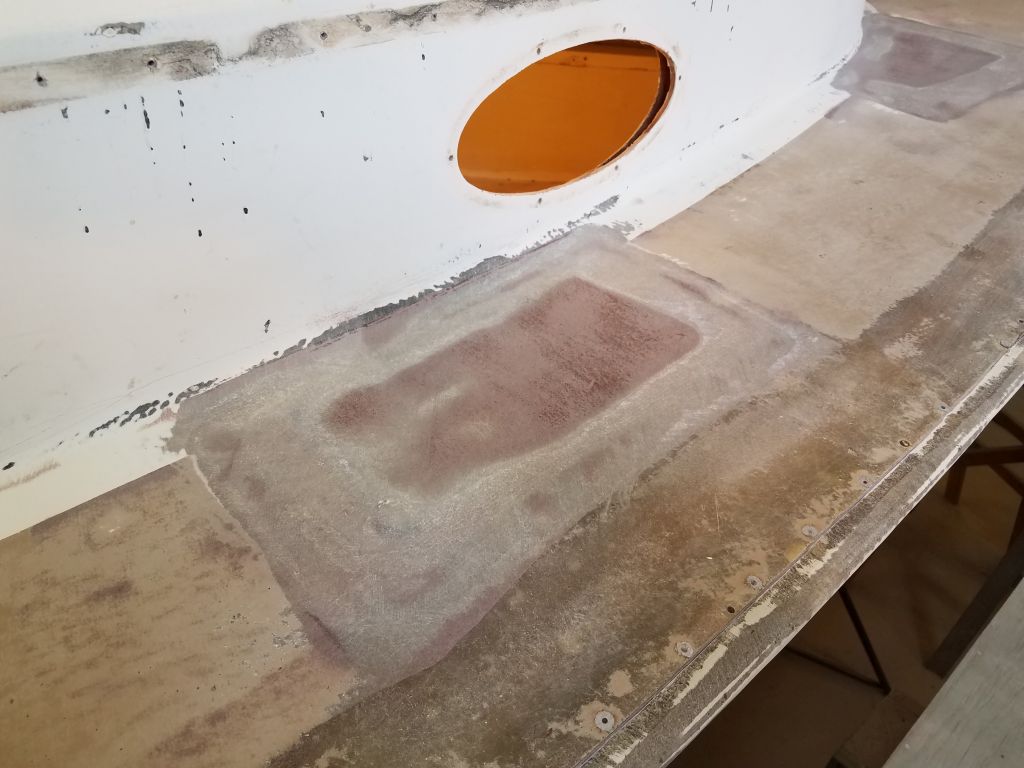
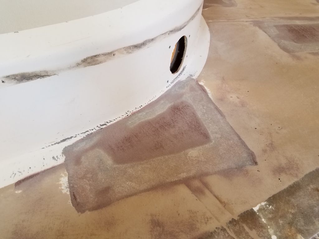
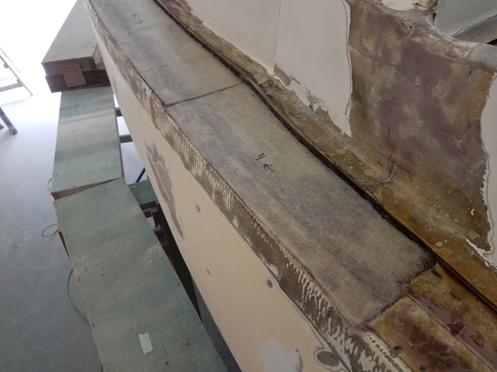
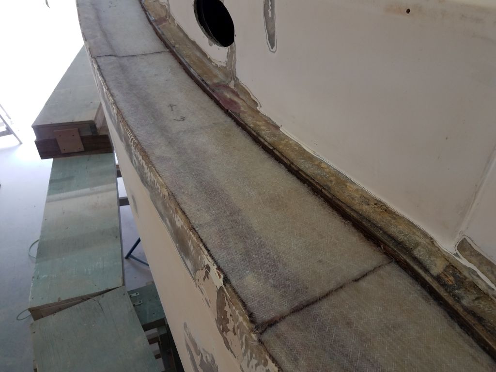
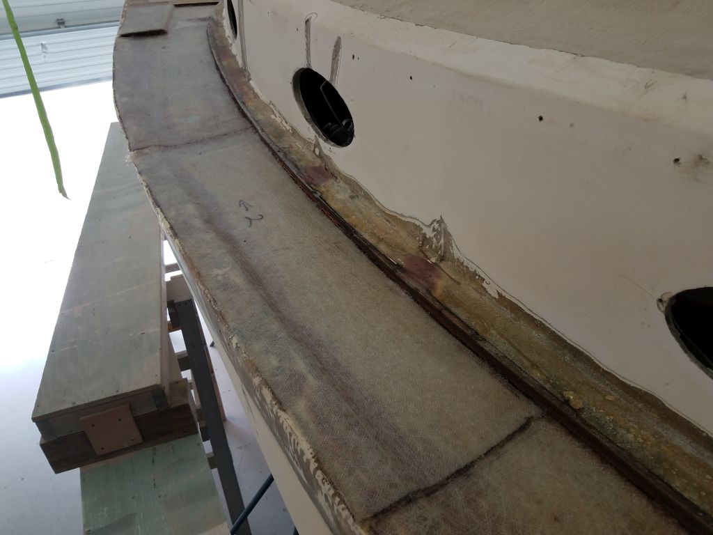
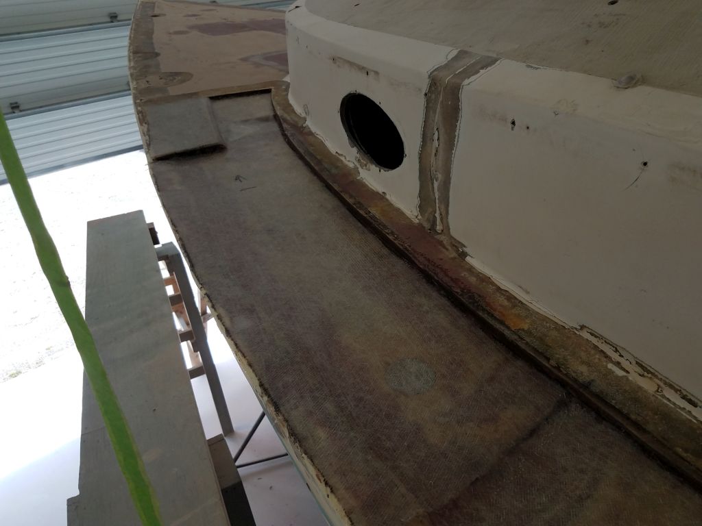
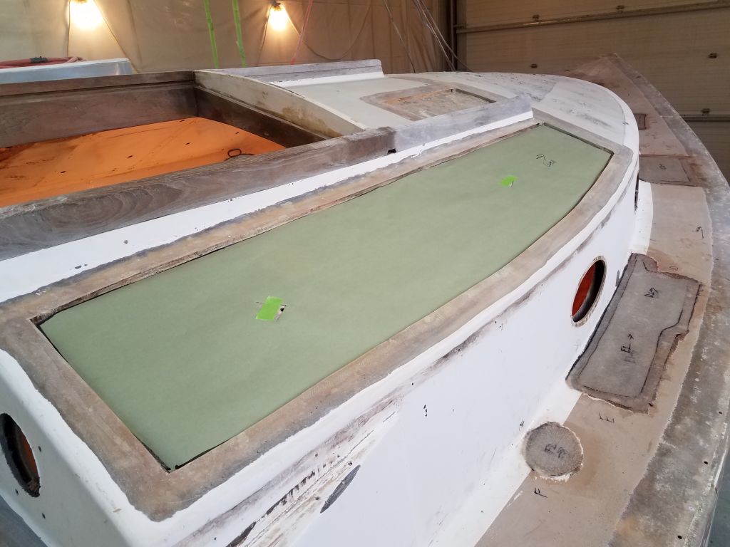
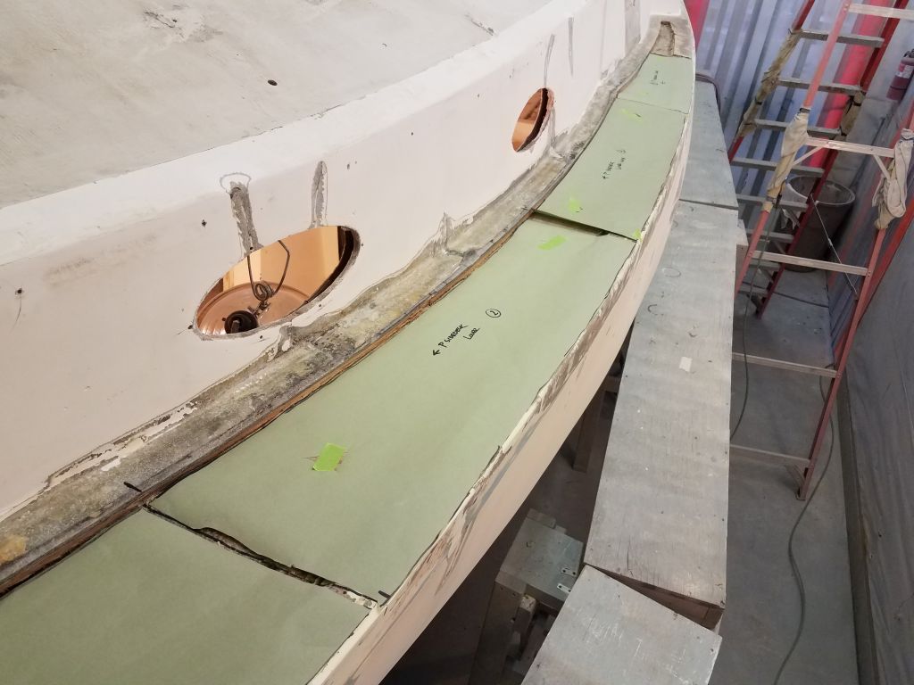
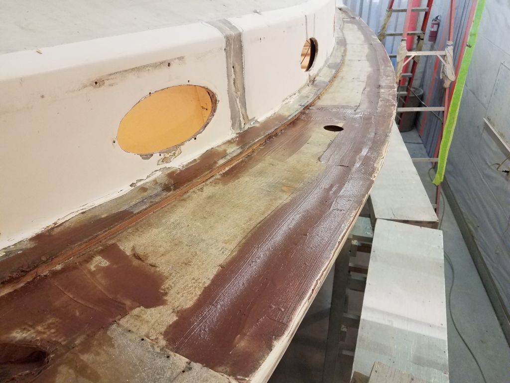
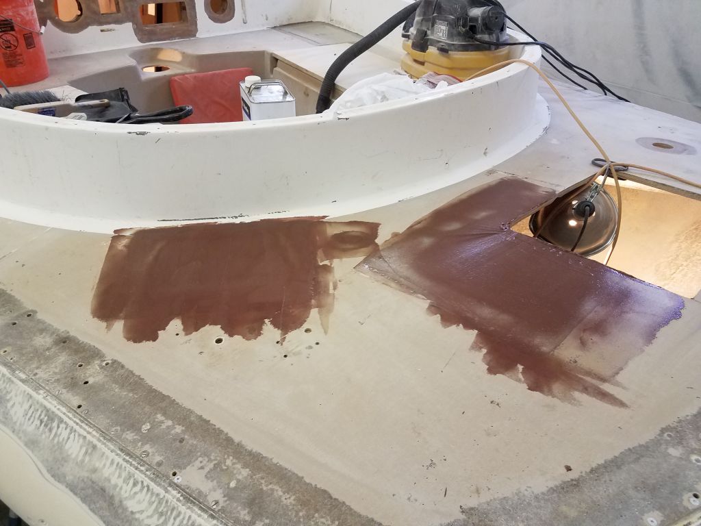
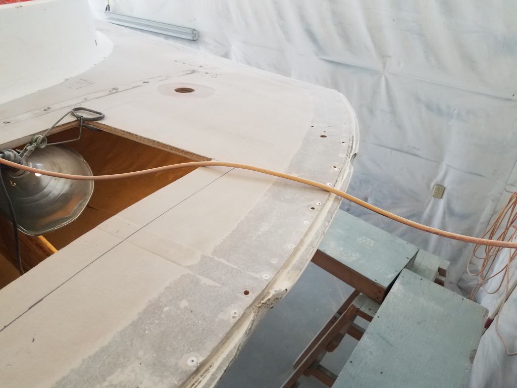
The port sidedeck was ready for its new layer of fiberglass over the inner skin, and I installed this now in epoxy resin. I extended the new material to the gunwale over most of the area, tying the inner skin back to the hull and hull flange as it should be. At the forward end, where the previous repair had met the existing decks in a messy and ineffective way, I brought the new inner skin layer up and over the adjacent top deck (which I’d prepared expressly for this purpose) to help reintegrate the whole structure again. I didn’t worry about the short void in the old inner skin and just spanned it with the new material, which drooped slightly into the old void. I’d bring this up level once the first layer cured and I could build on top of it.


I went around the boat again with fairing compound, applying a second coat to the main deck areas as needed, and the initial coat to the cockpit patches.


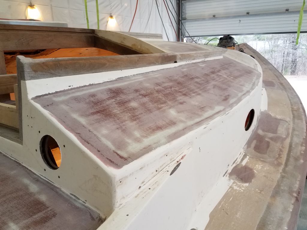
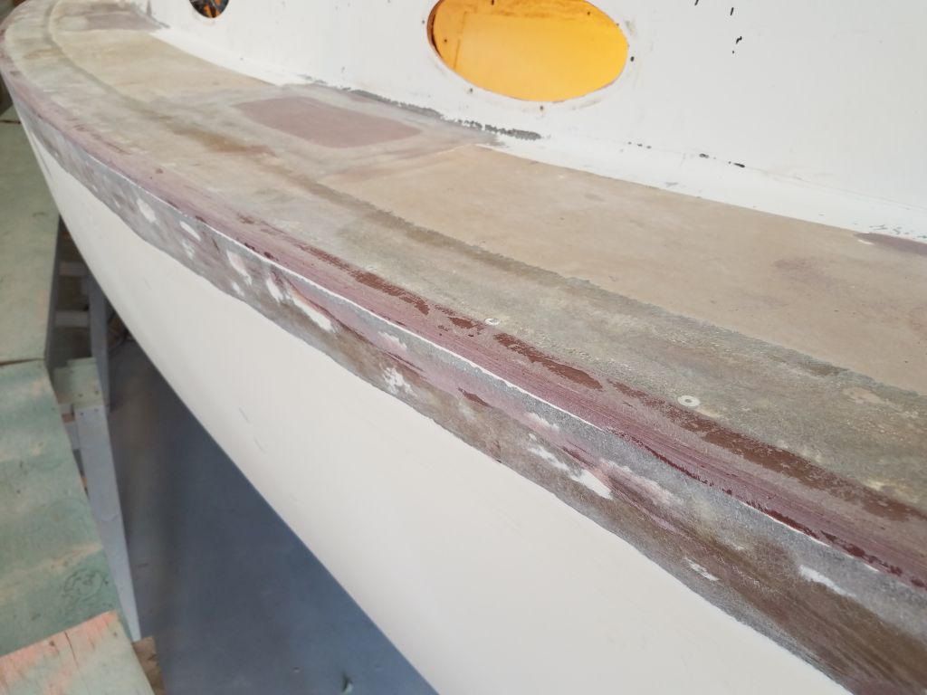
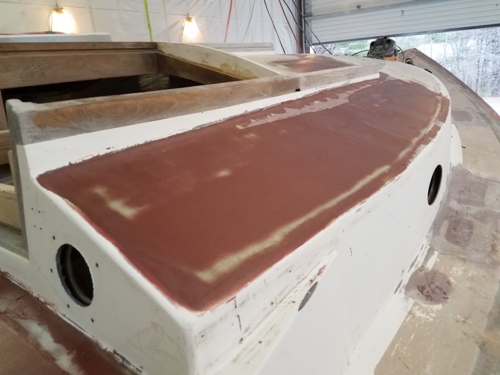
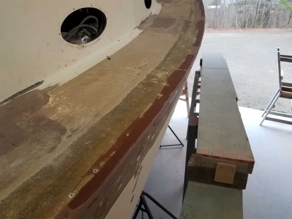
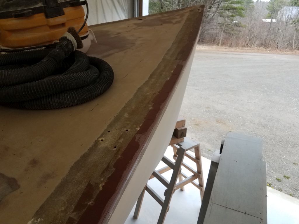
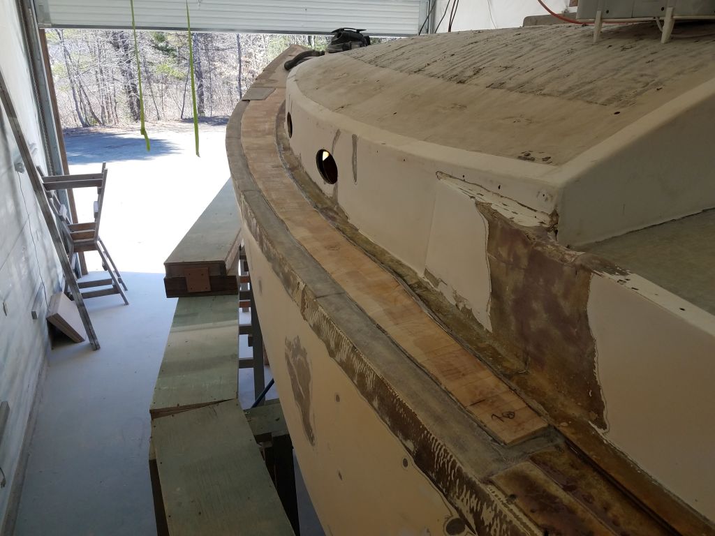
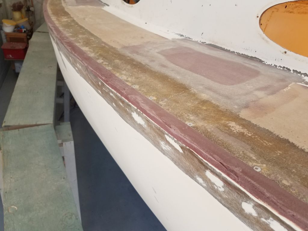
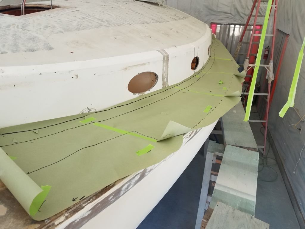
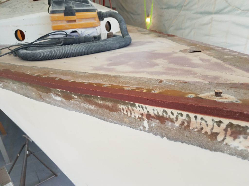
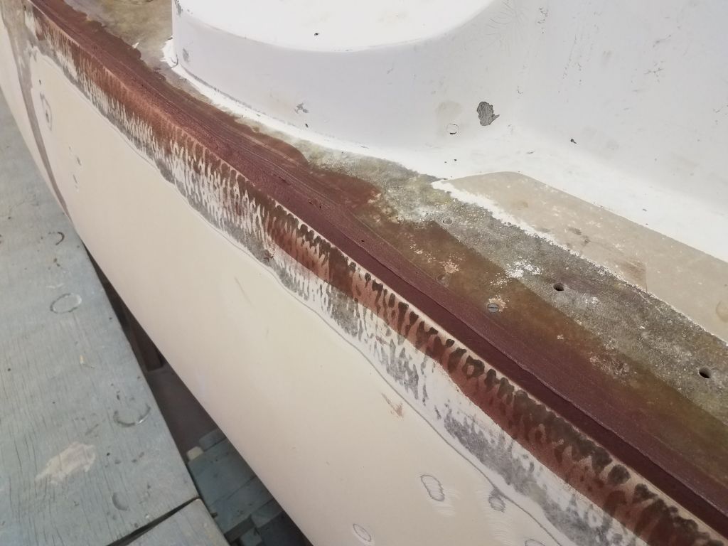
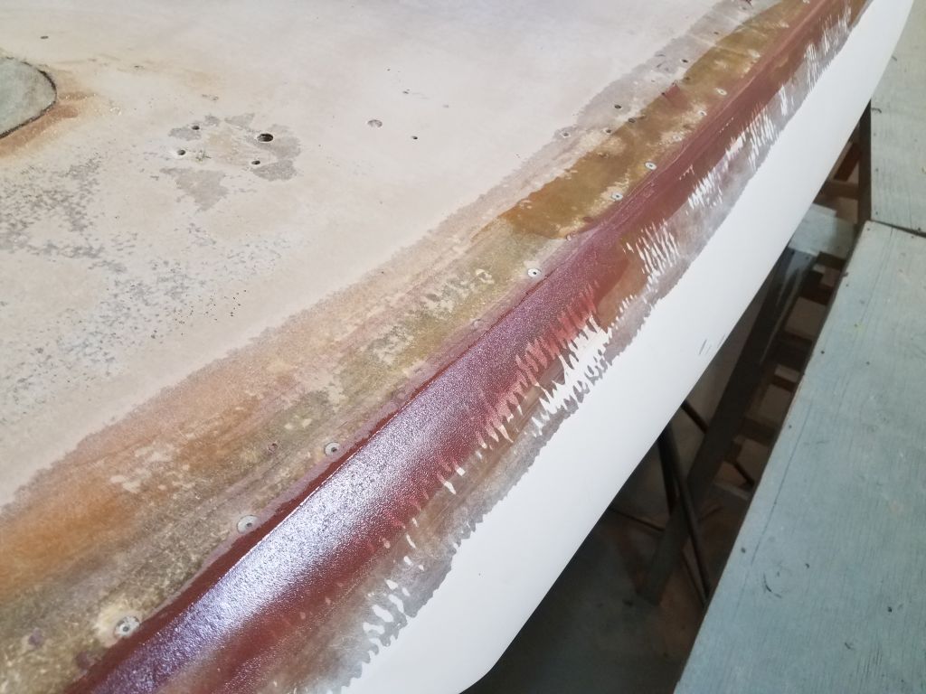
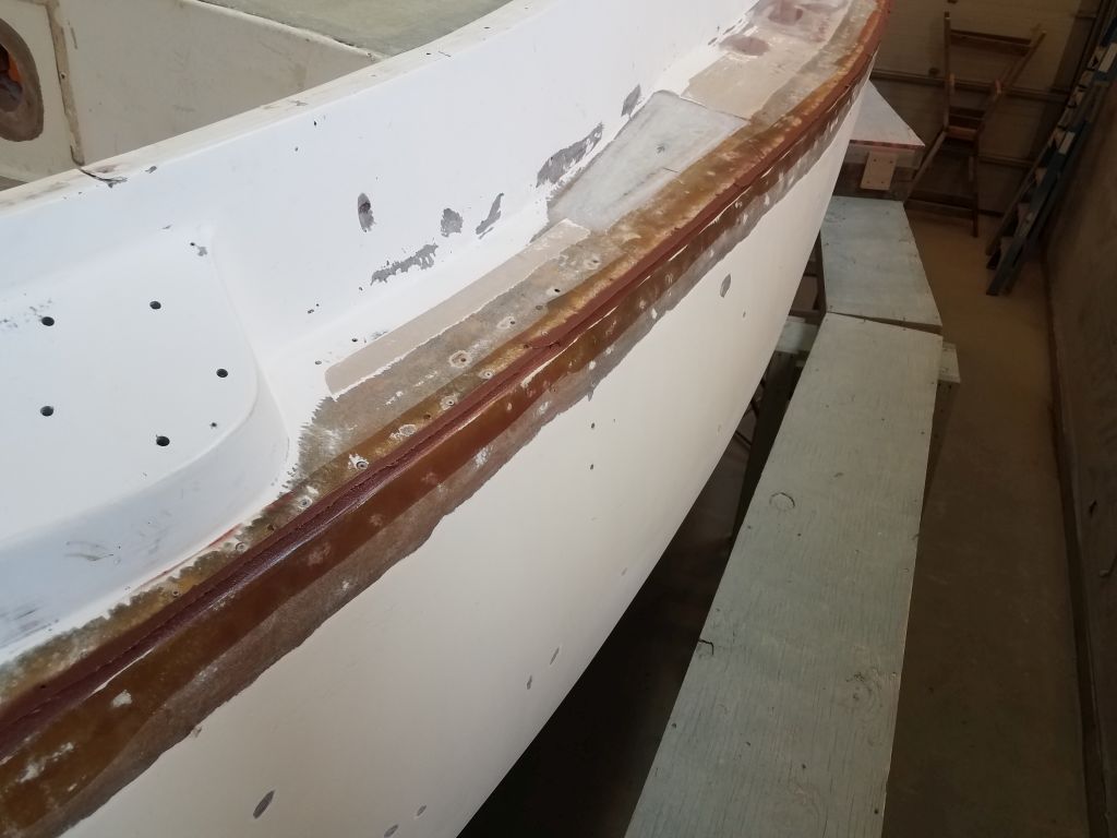
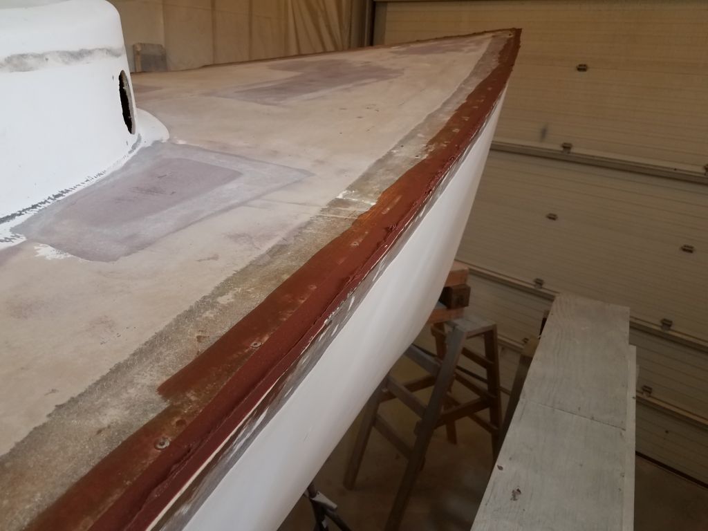
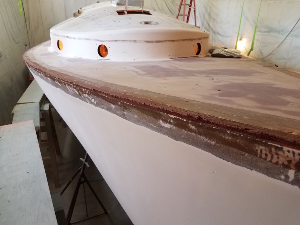
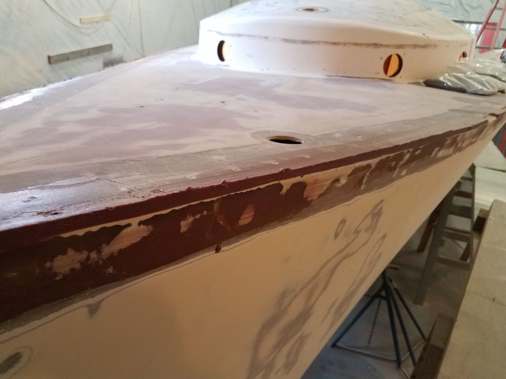
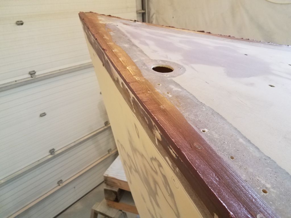
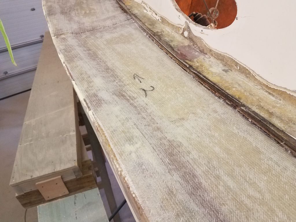
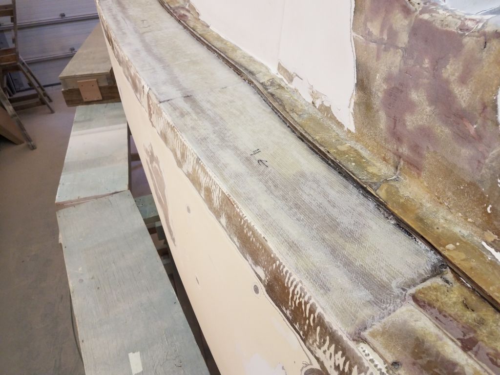
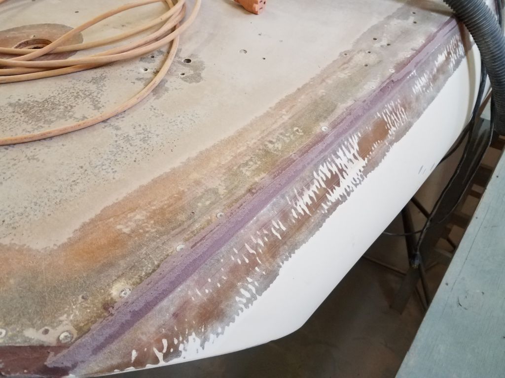
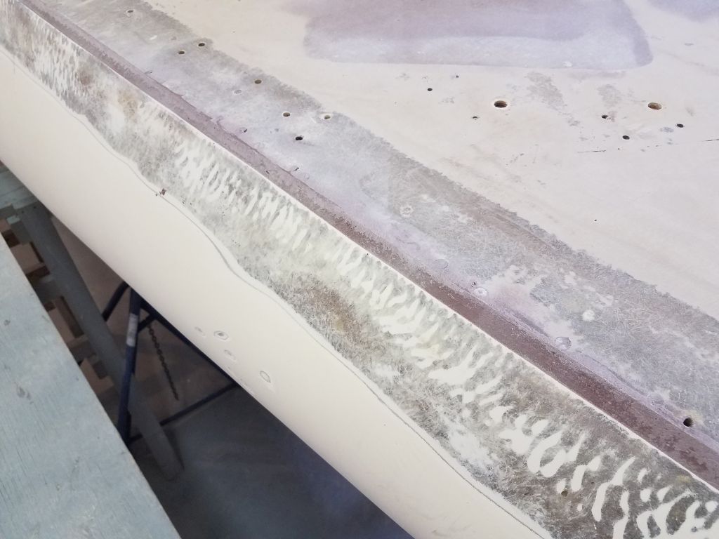
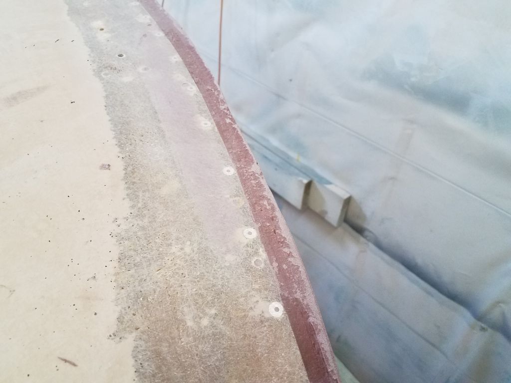
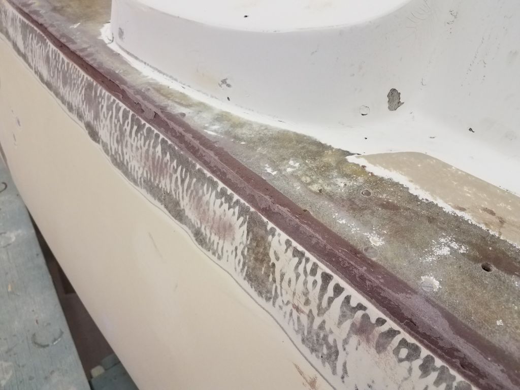
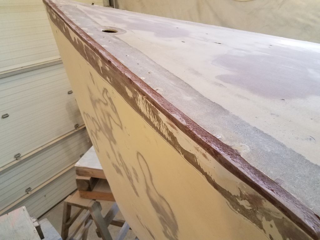
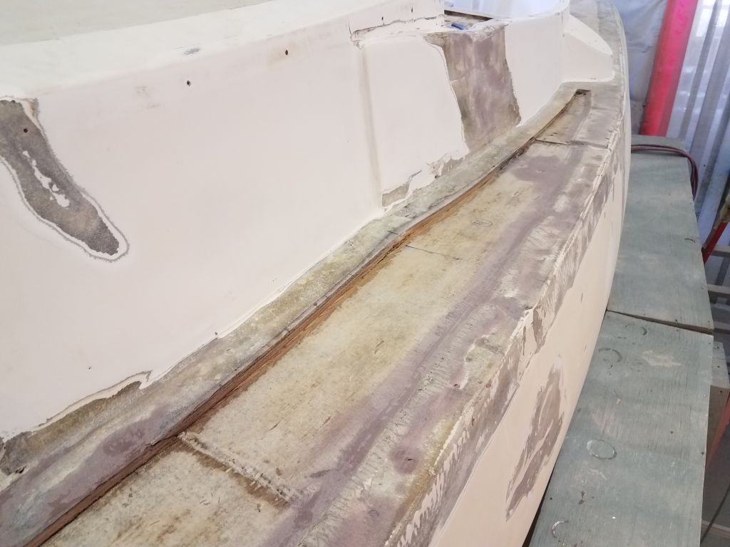
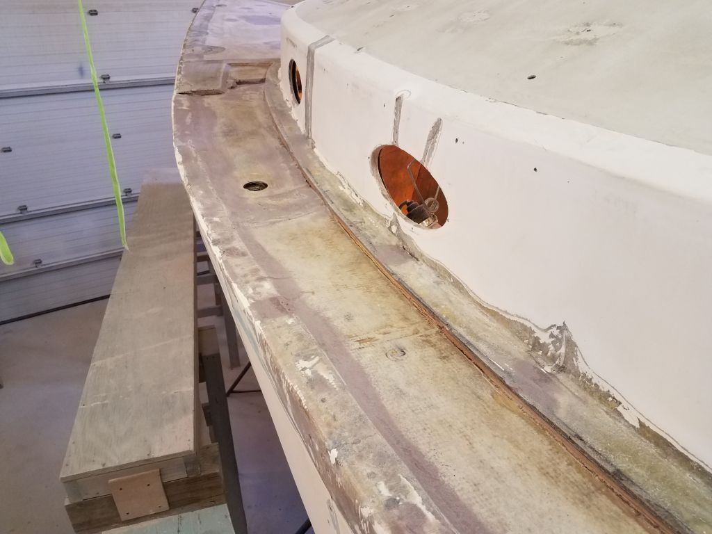
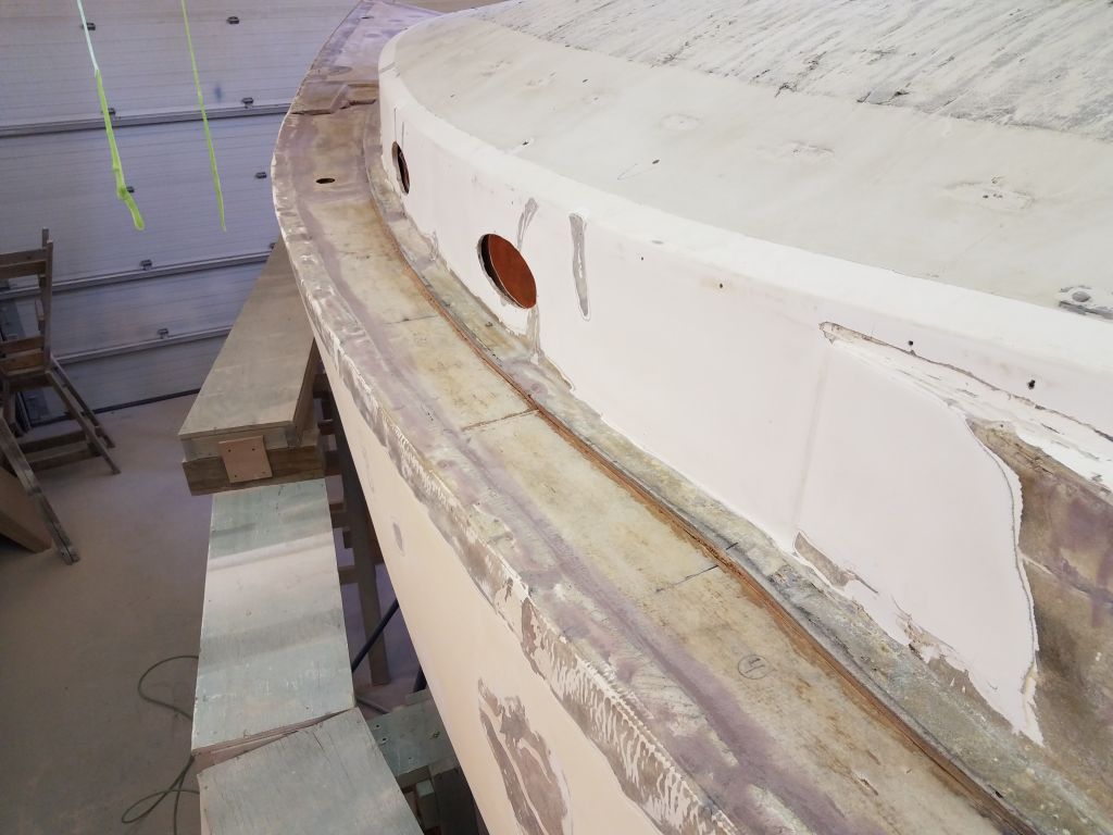
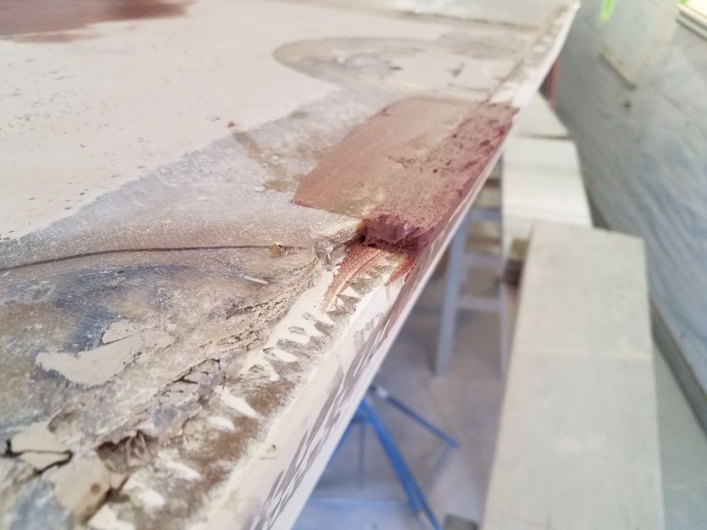
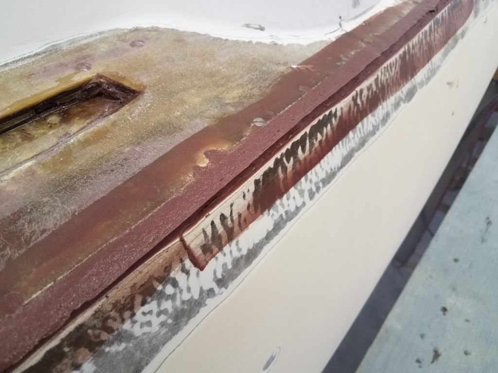
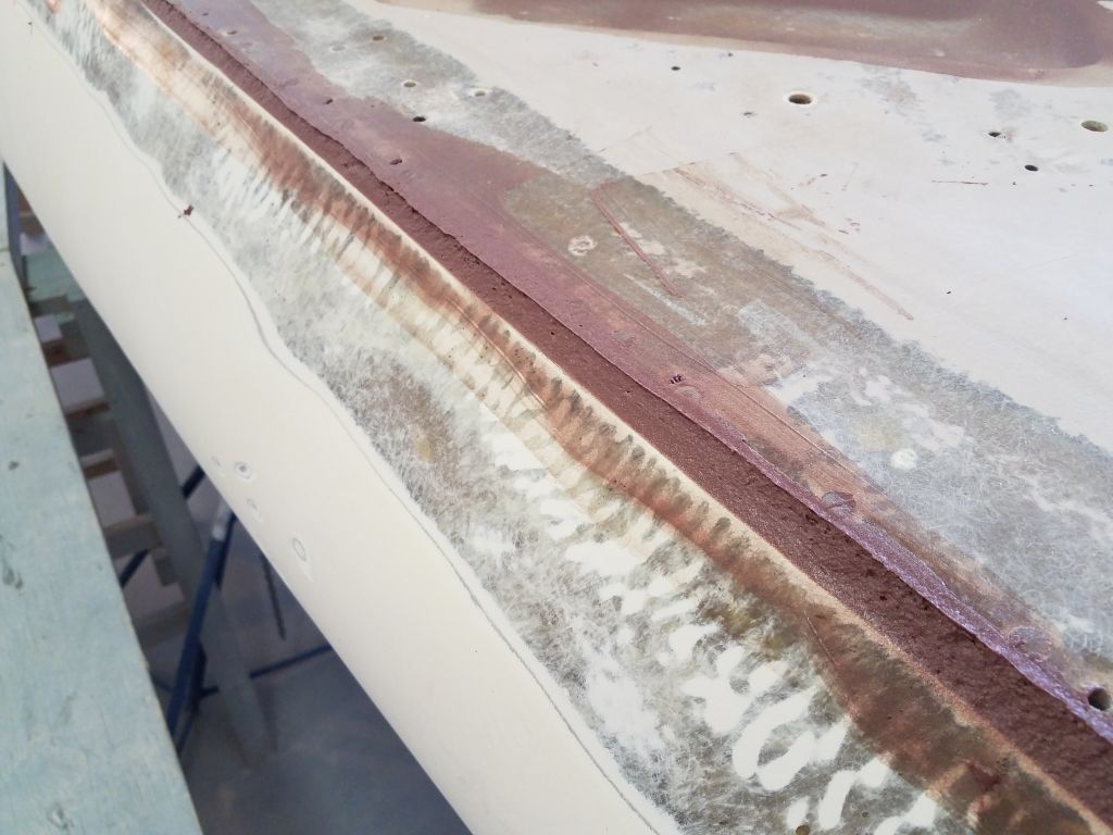
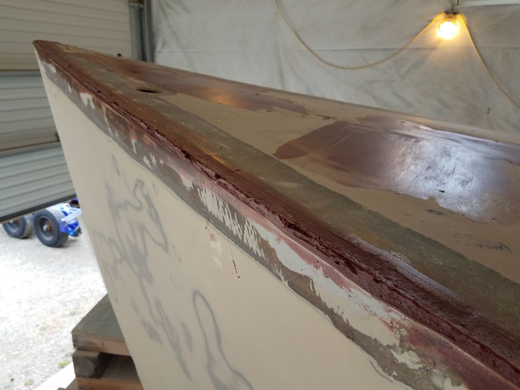
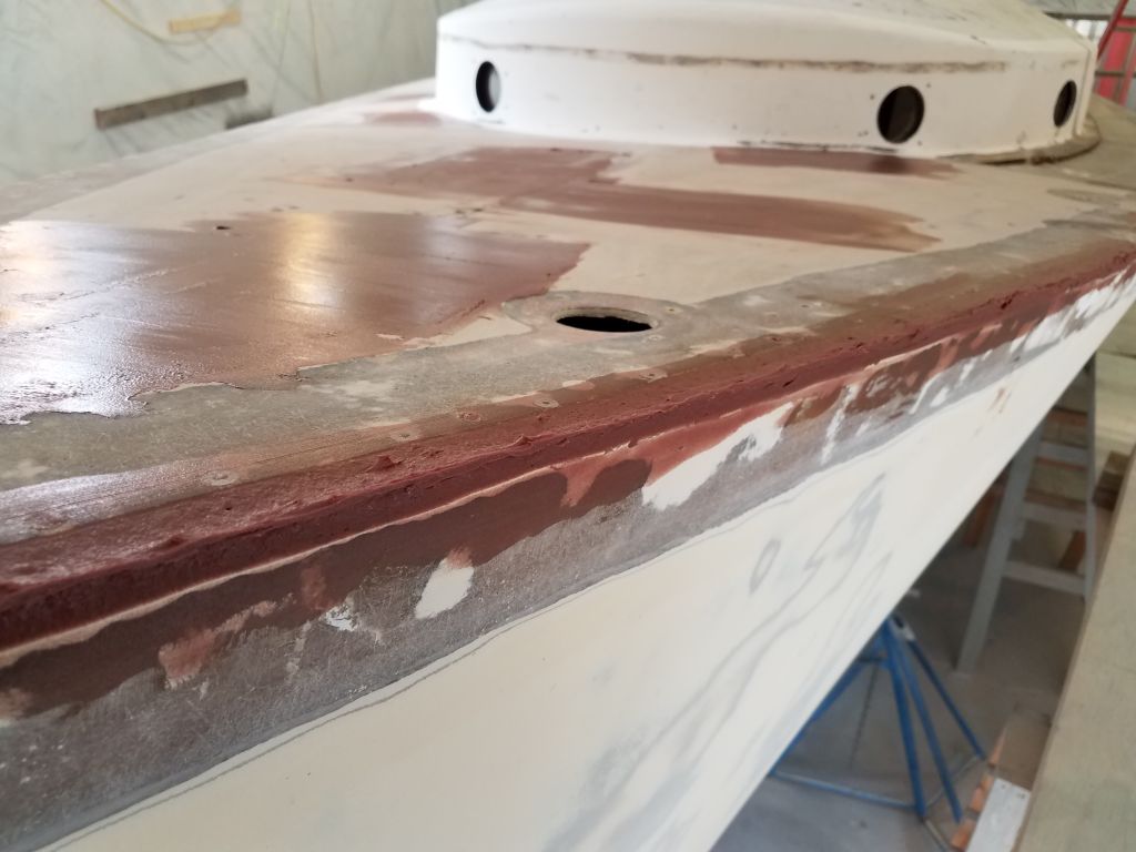
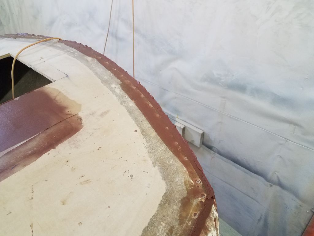
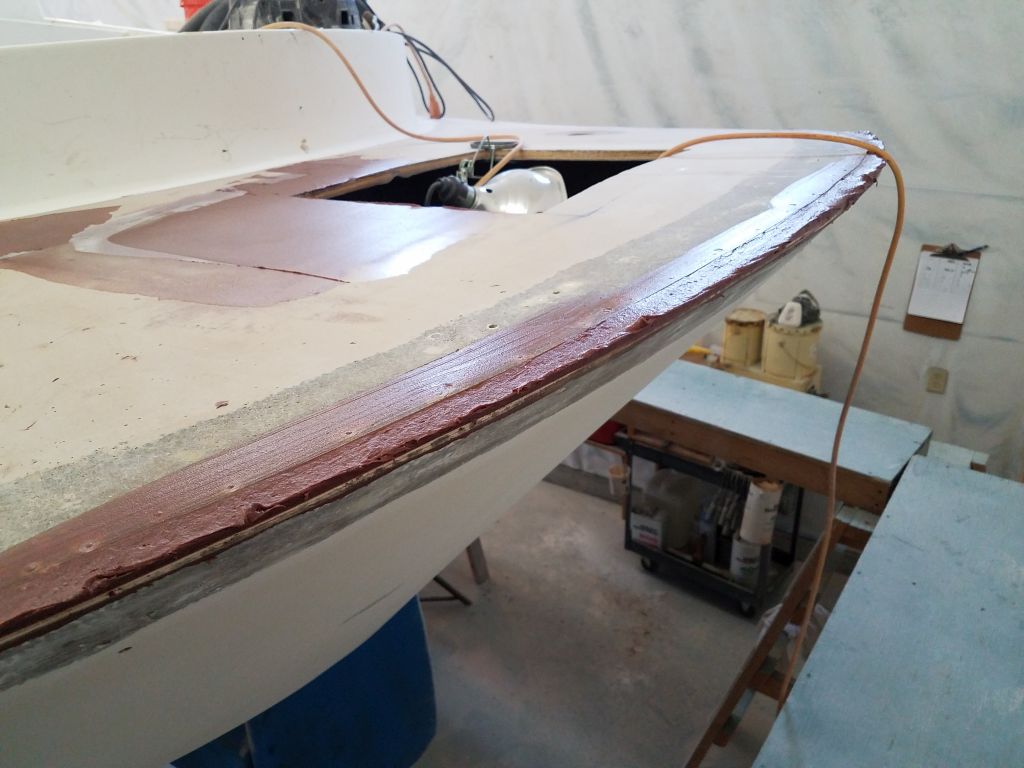
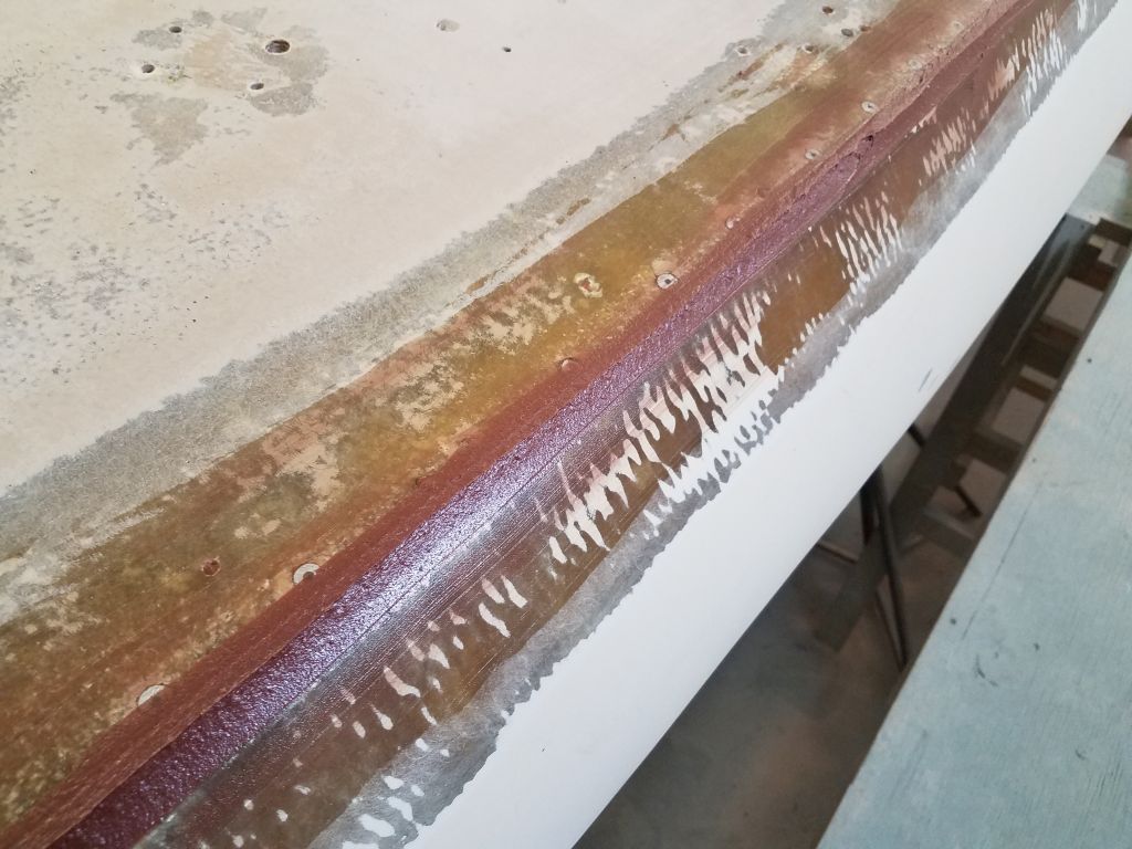
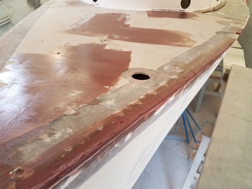
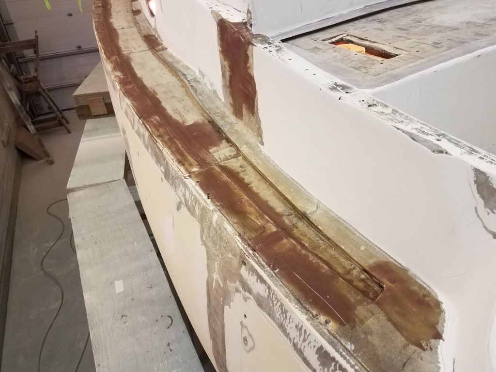
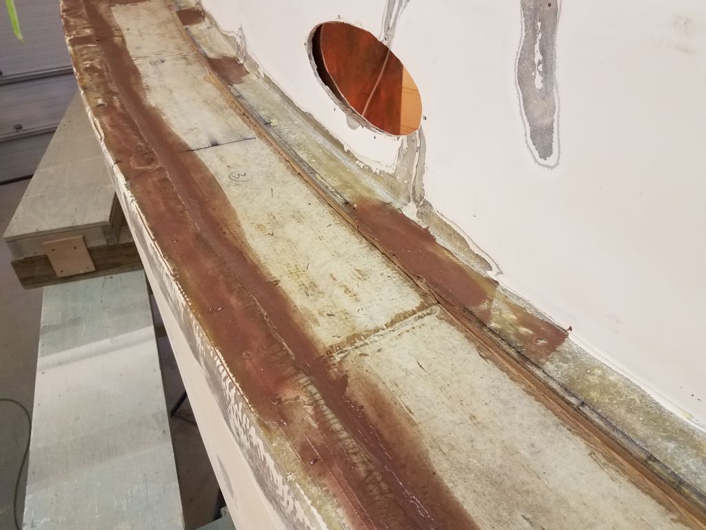
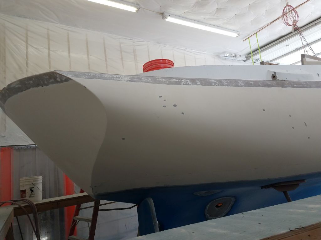
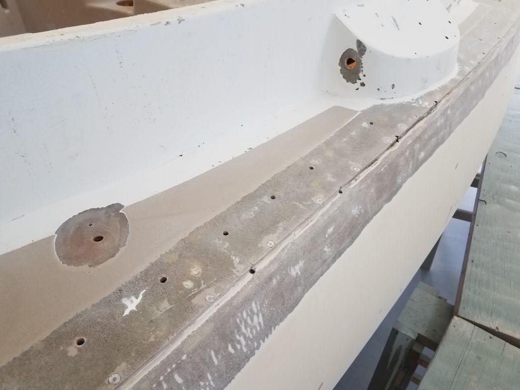
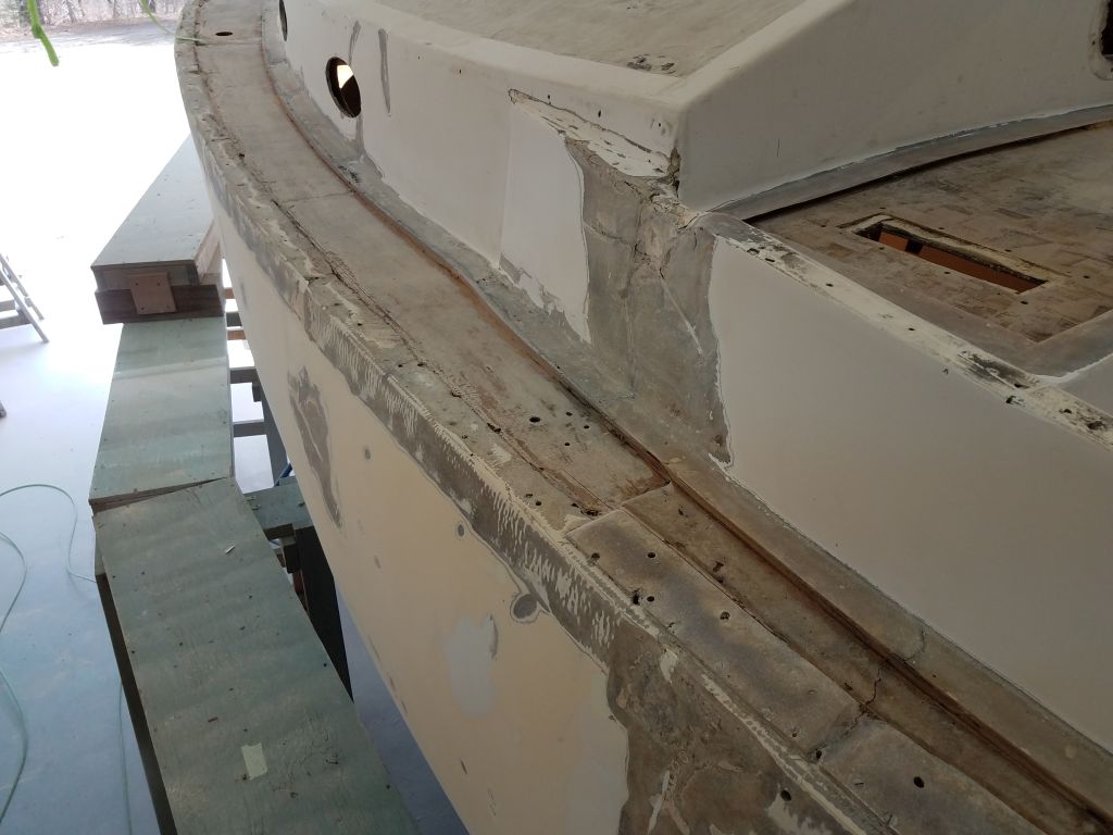
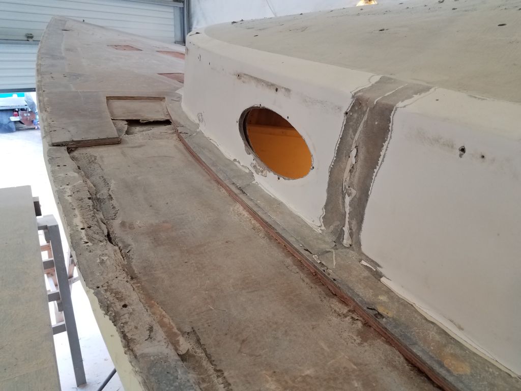
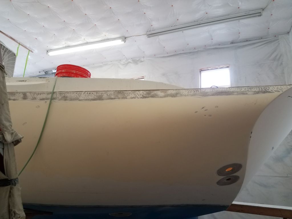
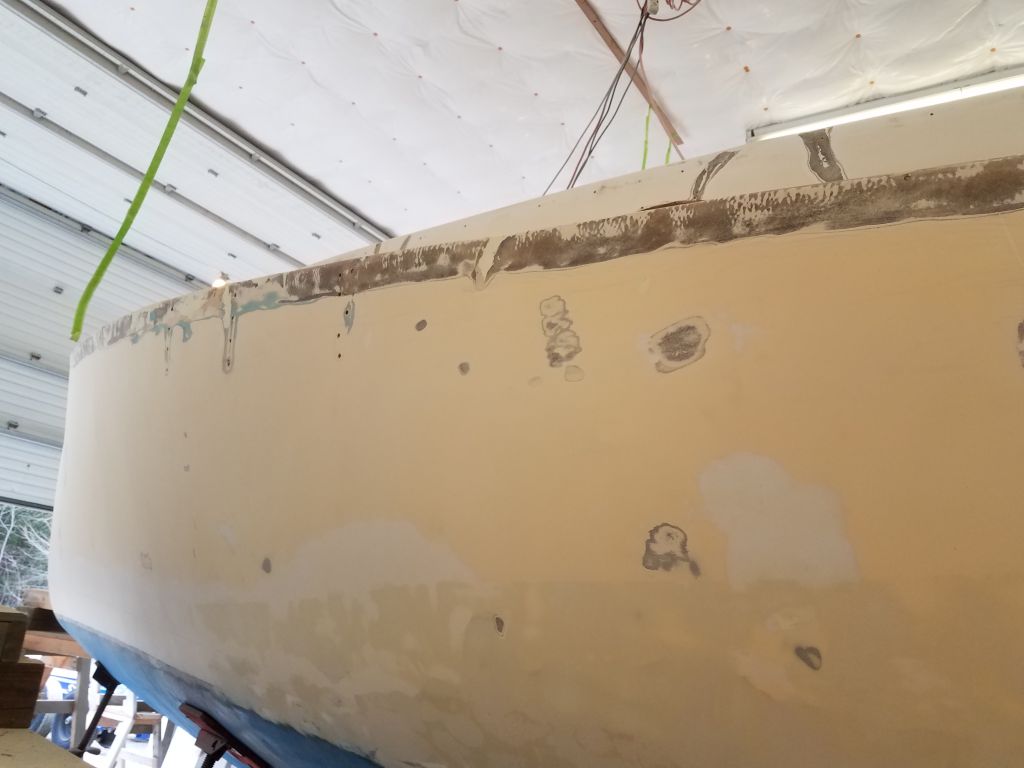
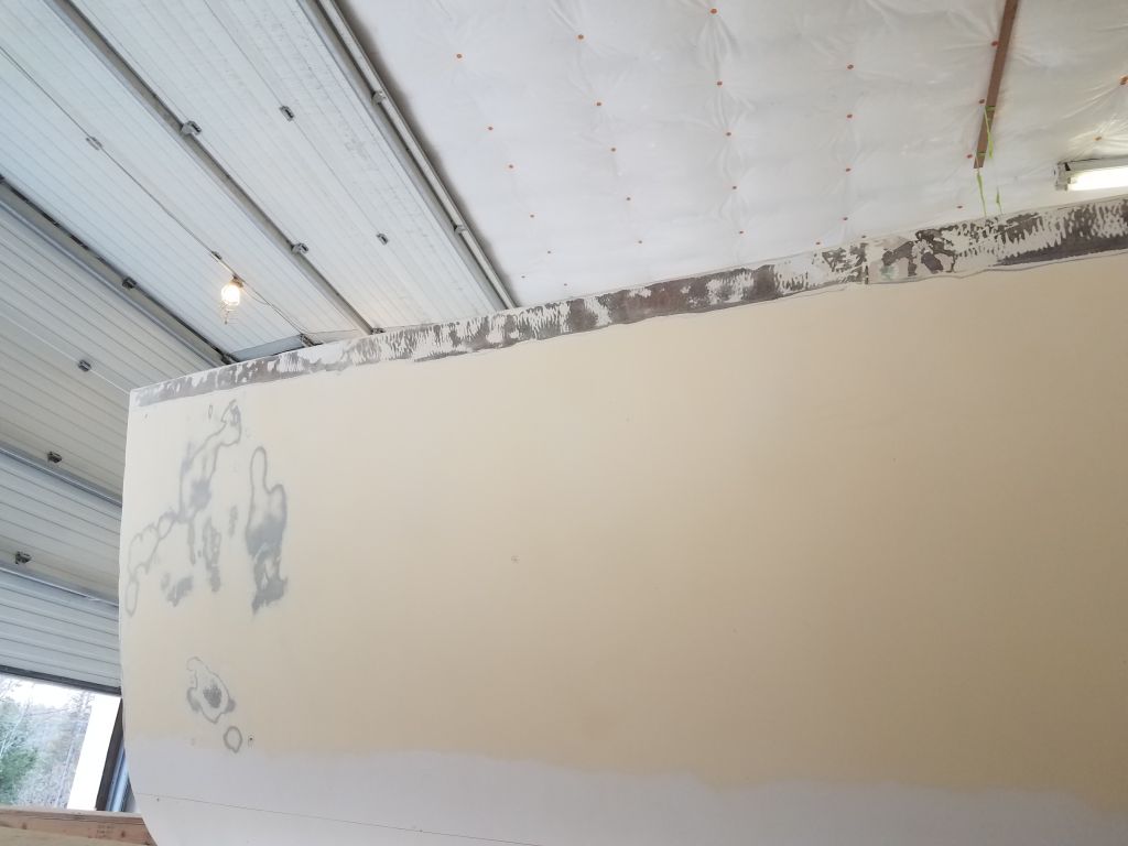
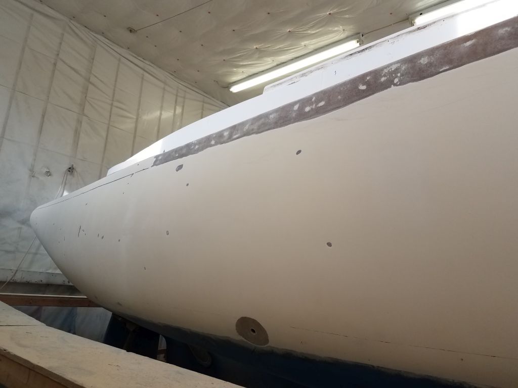
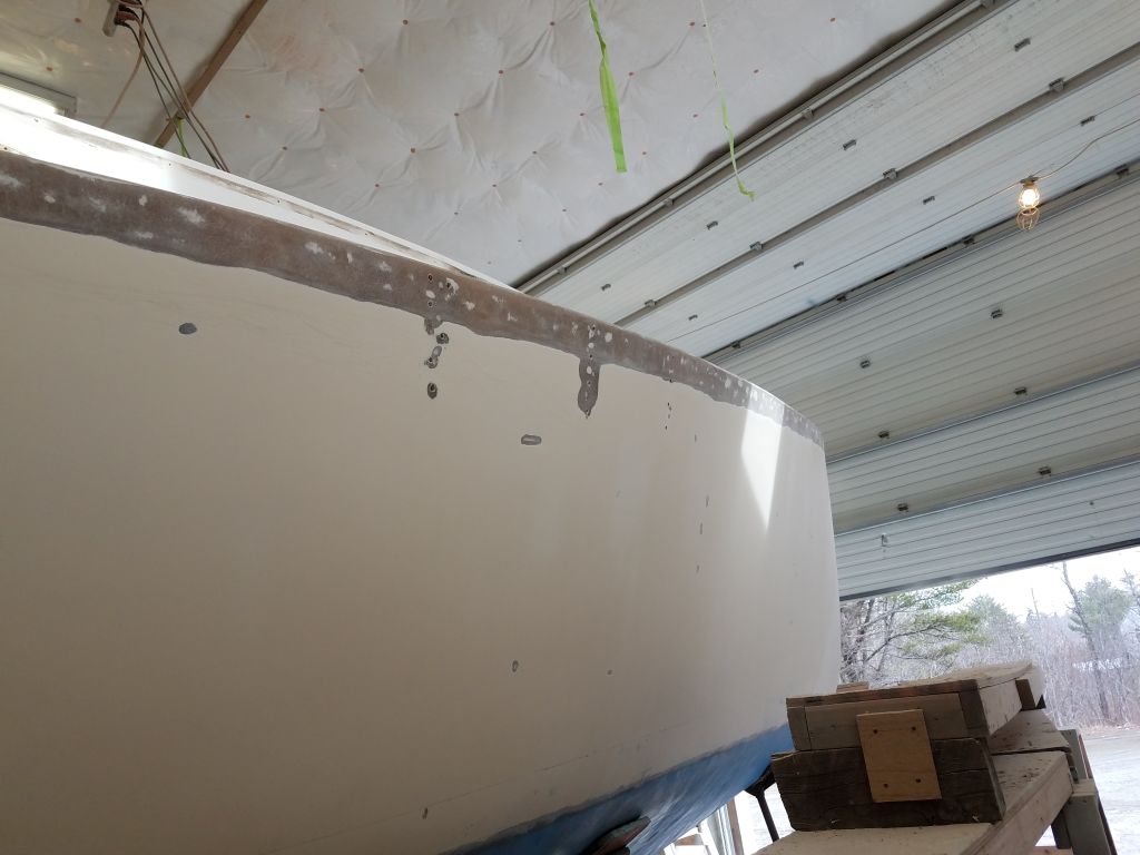
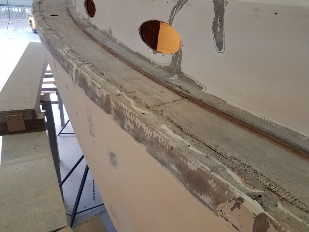
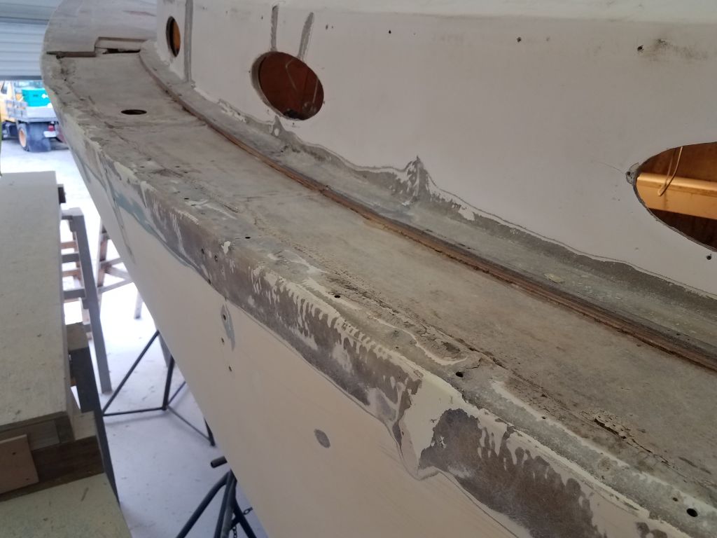
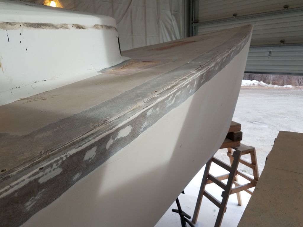
It was a good time to start filling the stepped edge between the gunwale and the edge of the deck molding. In order to achieve the final profile I wanted for the new hull-deck edge, as well as to provide a smooth corner for the fiberglass, I needed to fill the 1/4″ or so high space with epoxy. With a very thick mix of epoxy compound, I worked my way down the port side and across the transom to the starboard quarter, filling this flat area and using a trowel to rough it in to approximate the shape of the hull and deck, bringing the shape as close as I could for the initial application. I’d hoped to finish up the starboard side as well, but with a pending appointment arrival I didn’t want to get caught in the middle of an epoxy pot, so I stopped a little early.


Total time billed on this job today: 7 hours
0600 Weather Observation: 32°, cloudy. Forecast for the day: Mostly cloudy, around 50°
Tuesday
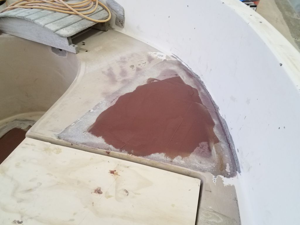
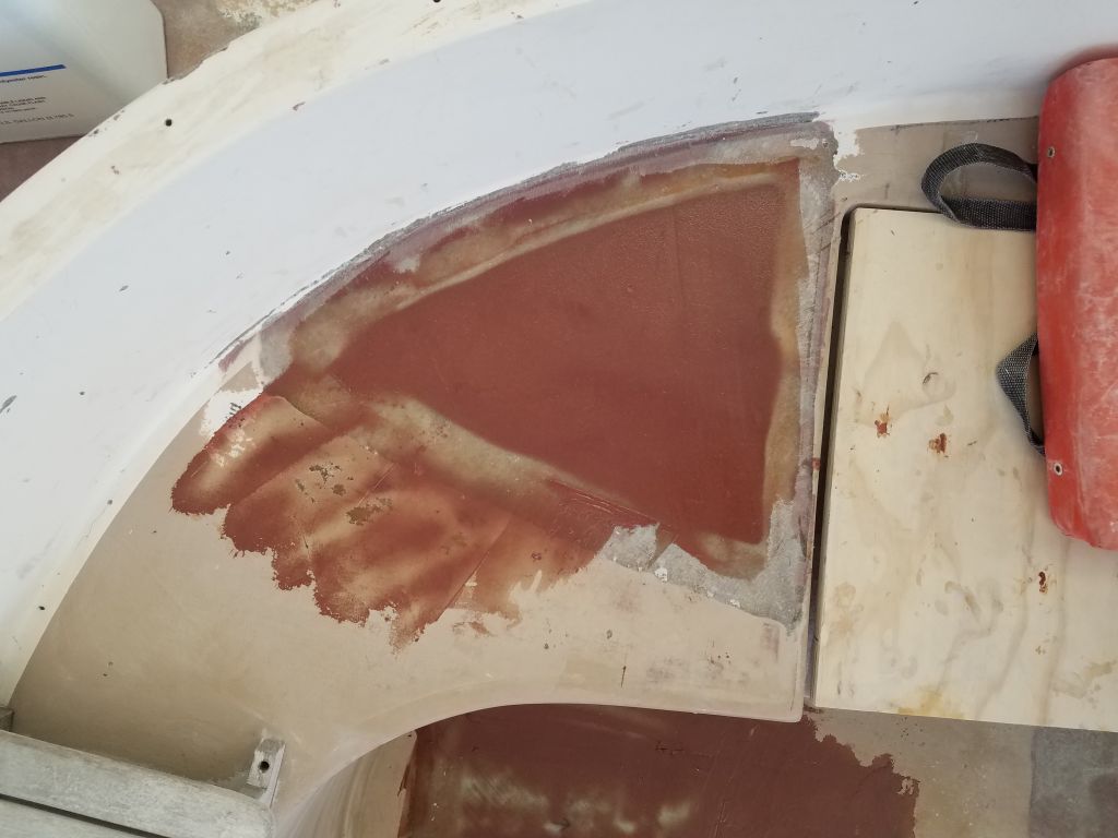
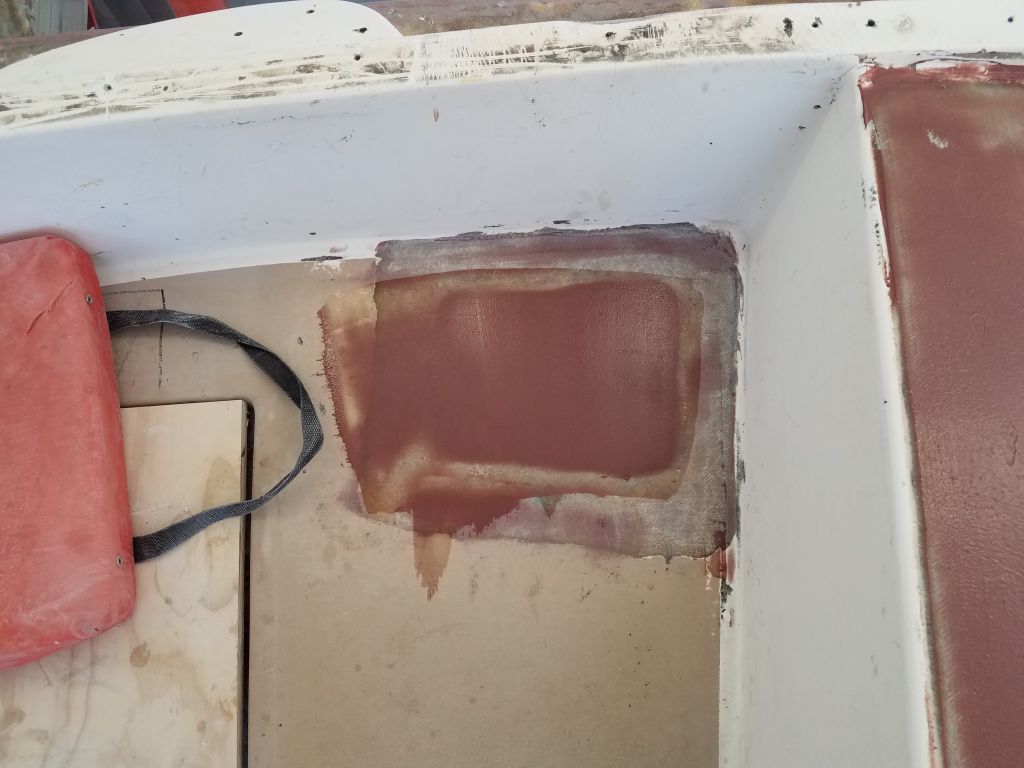
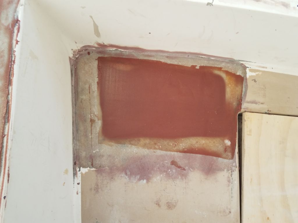
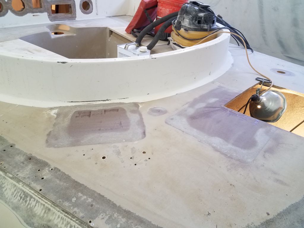
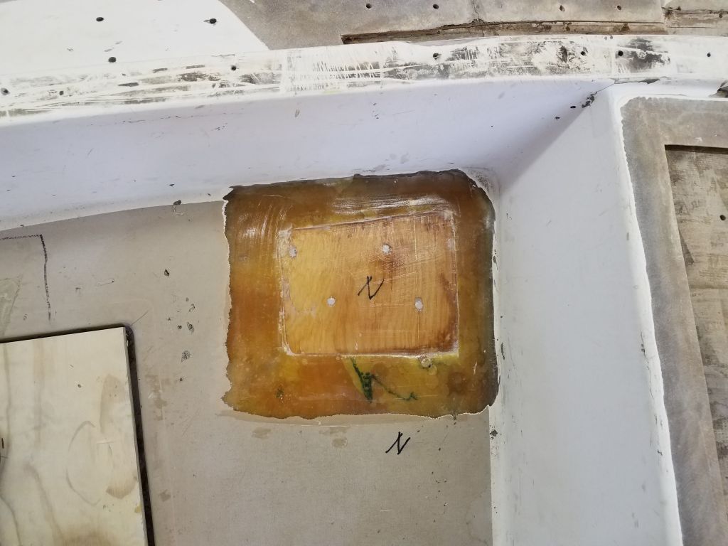
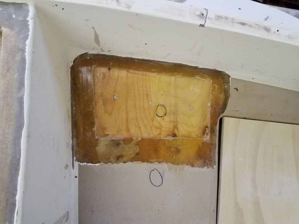
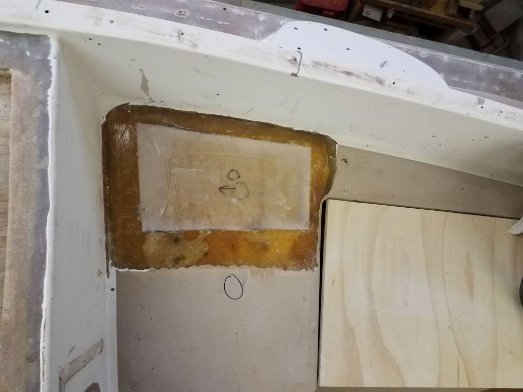
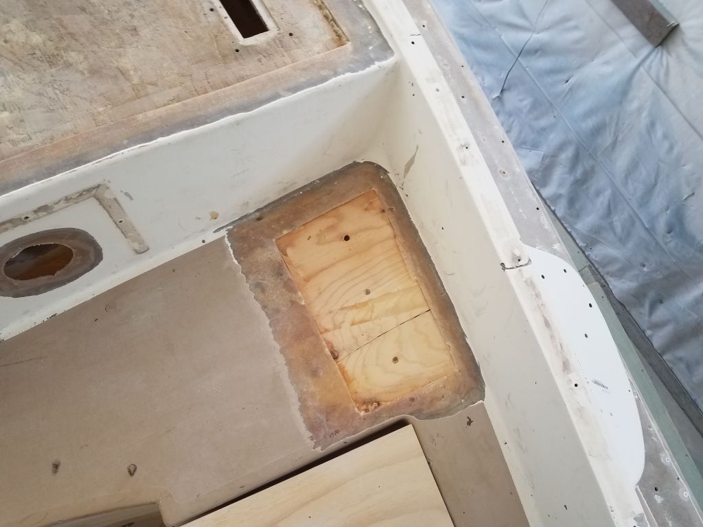
In the cockpit, I got started with the remaining top skin deck patches. After final cleanup, I used thickened epoxy to fill small voids and holes in the exposed plywood core, and wet out the core and surrounding areas. Then, I installed three layers of fiberglass in epoxy resin to complete the repairs. I left the area around the steering pedestal hole for later, as I still had to prepare and fill the large hole in the sole first.

Next, I made paper patterns of the deck sections to be recored: two areas on the coachroof and the bridgedeck, plus a small section of the starboard sidedeck outboard of the cockpit.
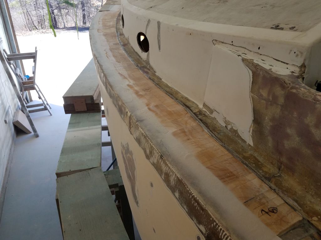
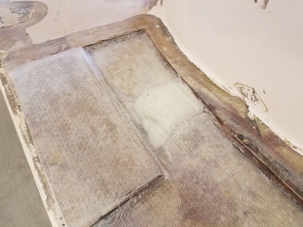
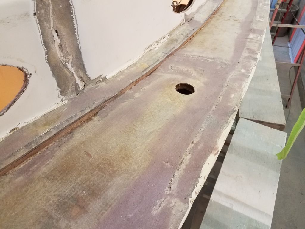
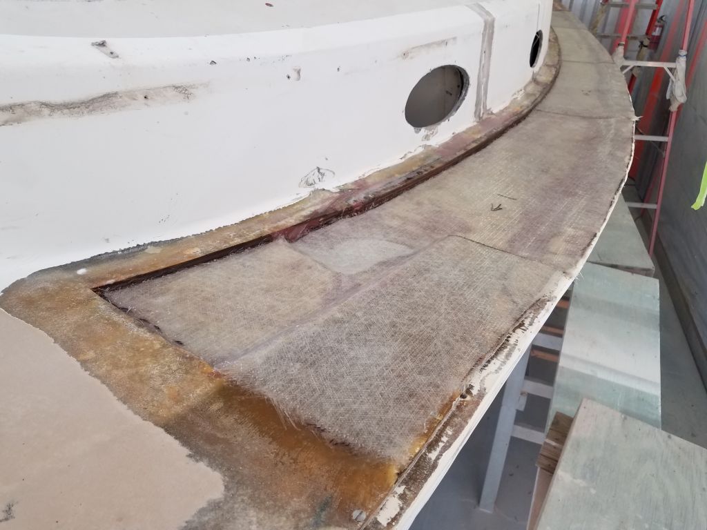
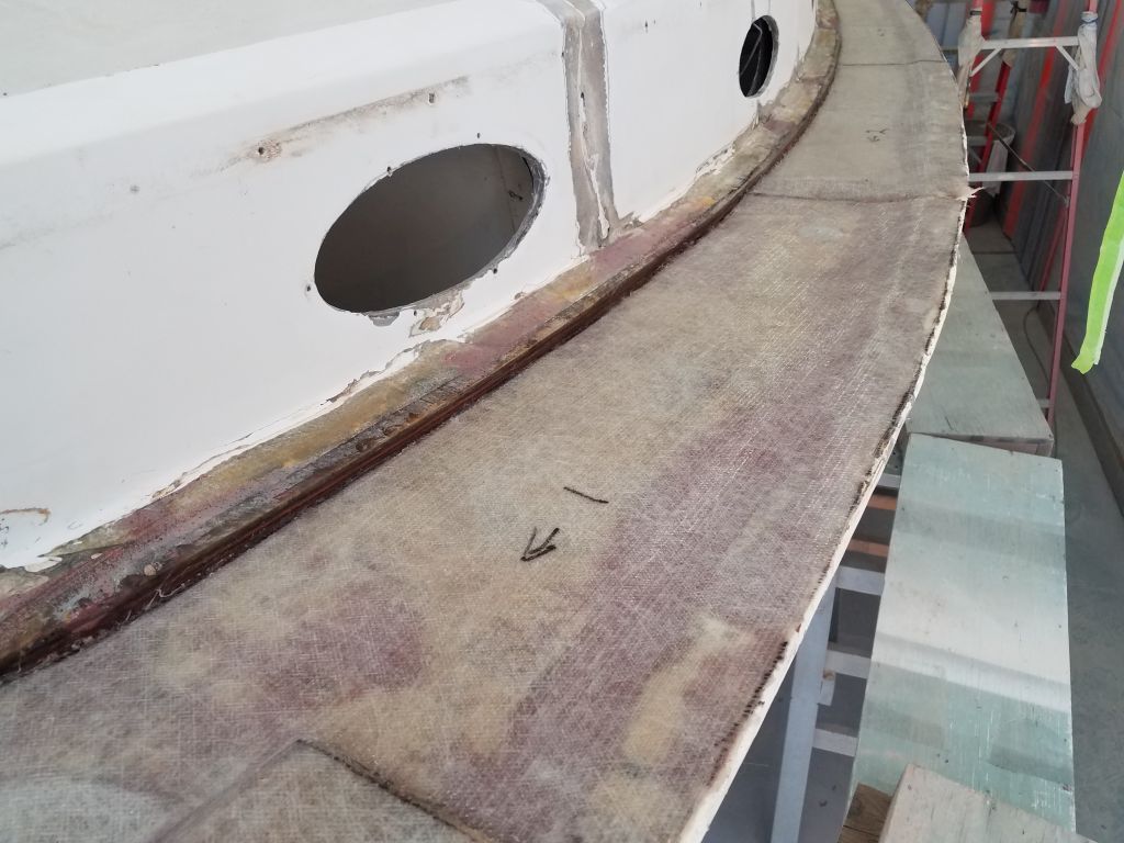
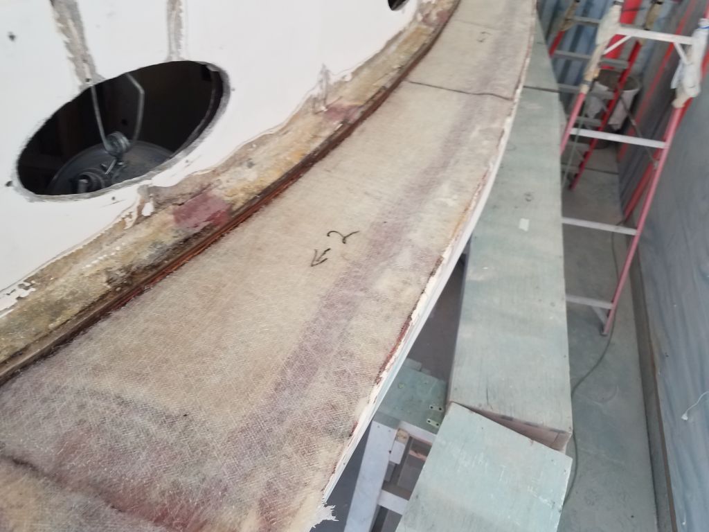
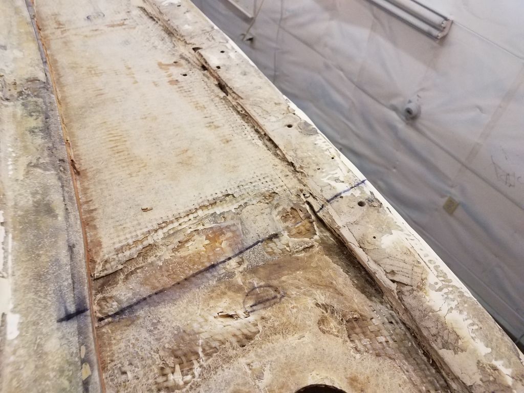
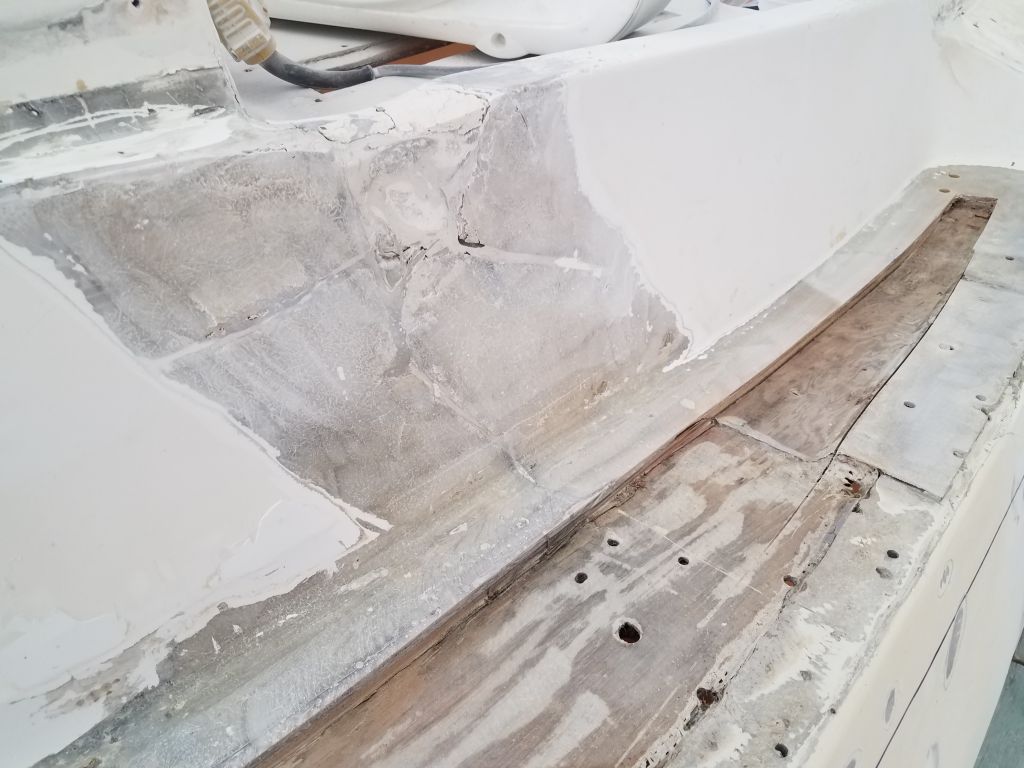
My plan for rebuilding the port sidedeck included starting with a new layer of fiberglass over the existing inner deck skin. This would help tie in the existing skin with the surrounding structures again, including the hull/deck flange, as well as provide a sound base for the new core and top laminate. To this end, I made patterns of the area that I used to cut new 1708 fabric in several pieces to fit. The new glass would extend from the inner edge of the old core, near the flange at the cabin trunk, all the way to the edge of the hull to tie the whole area together.
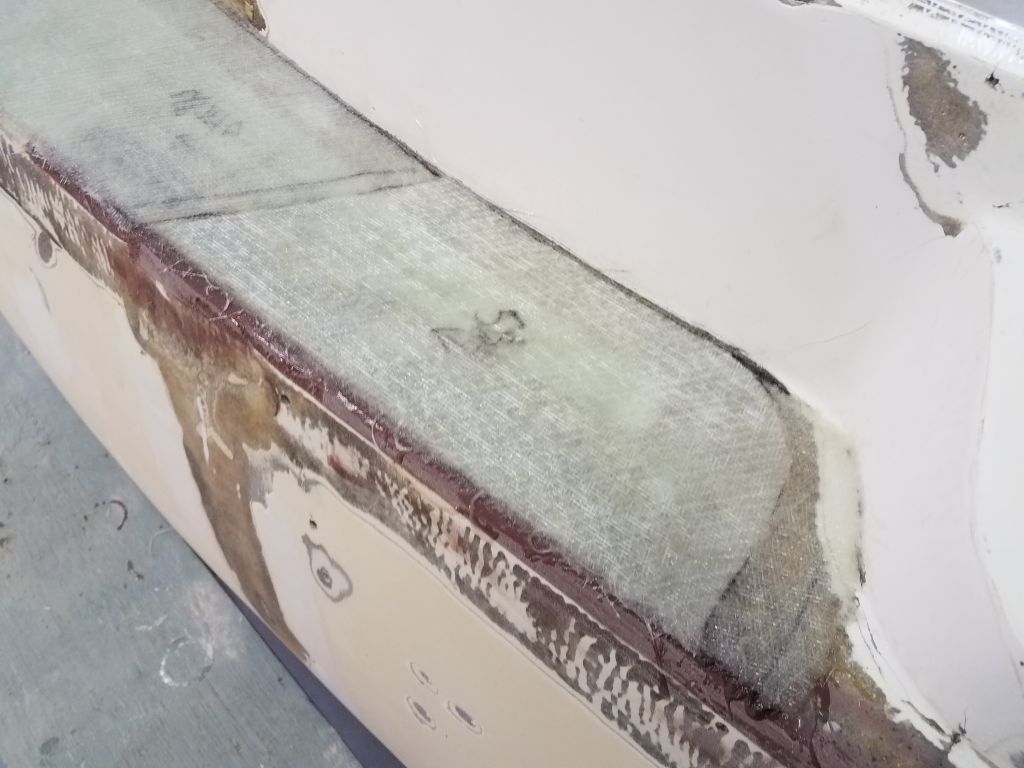
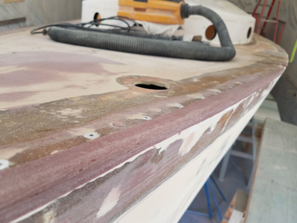
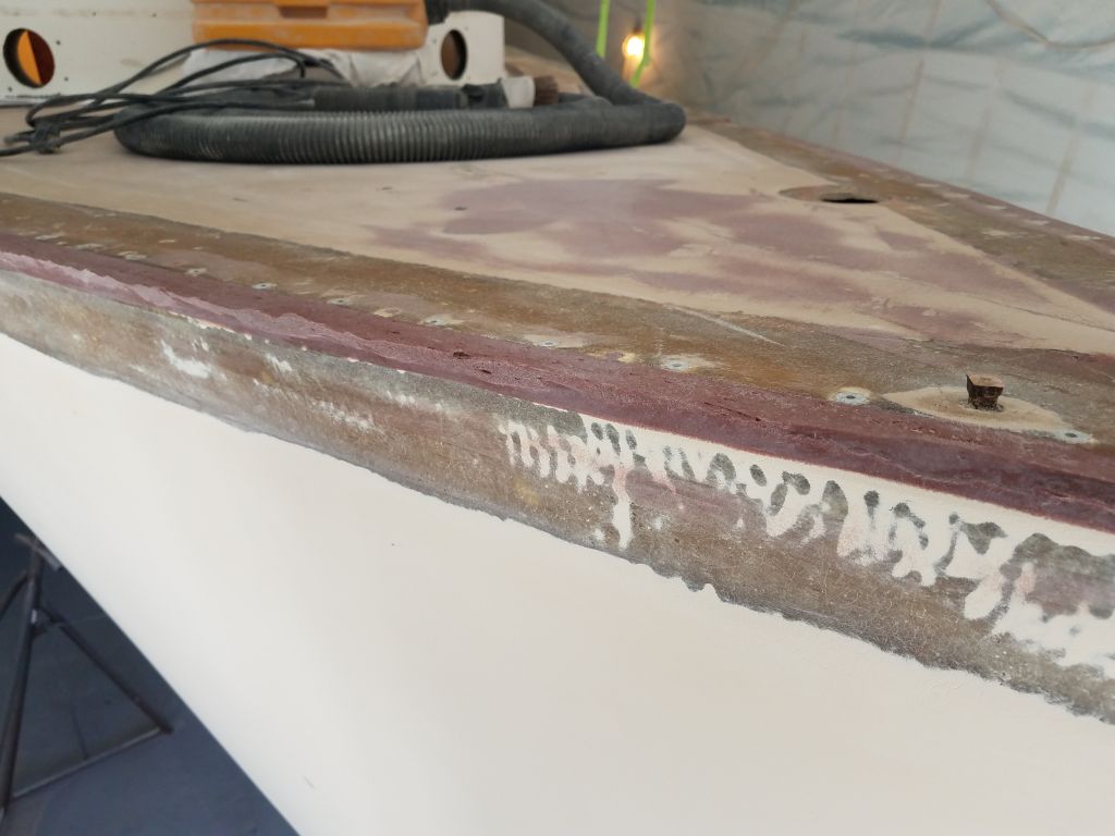
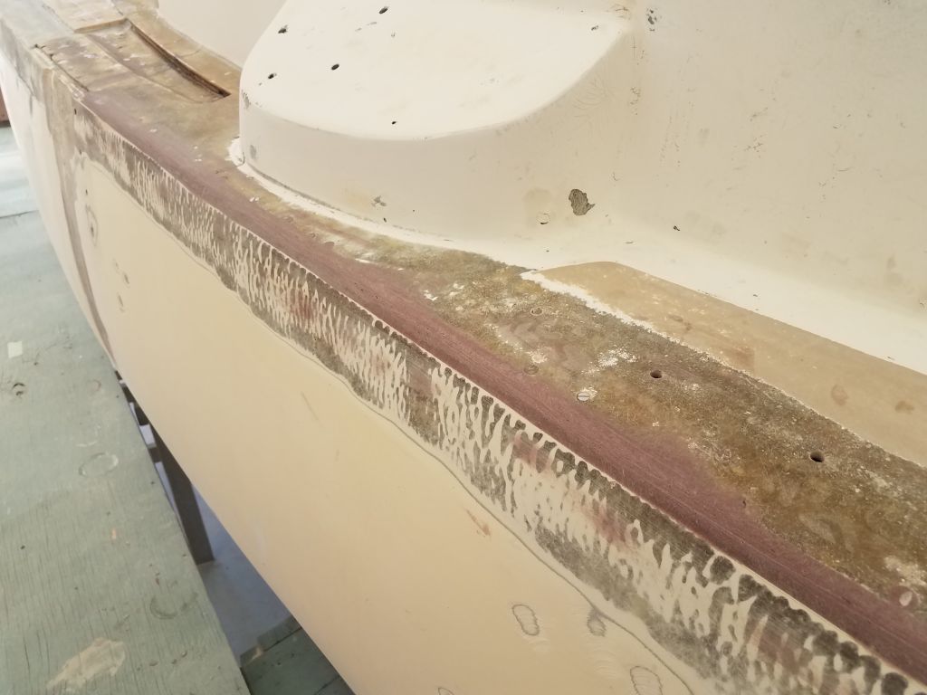
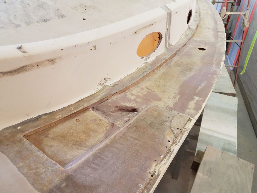
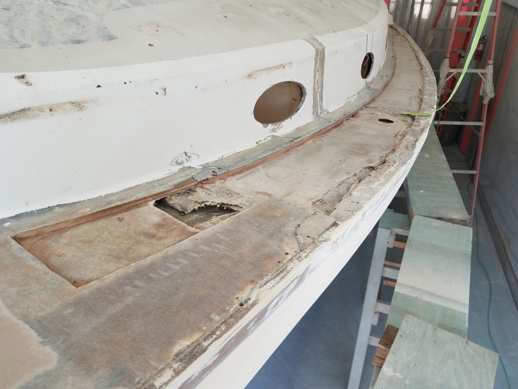
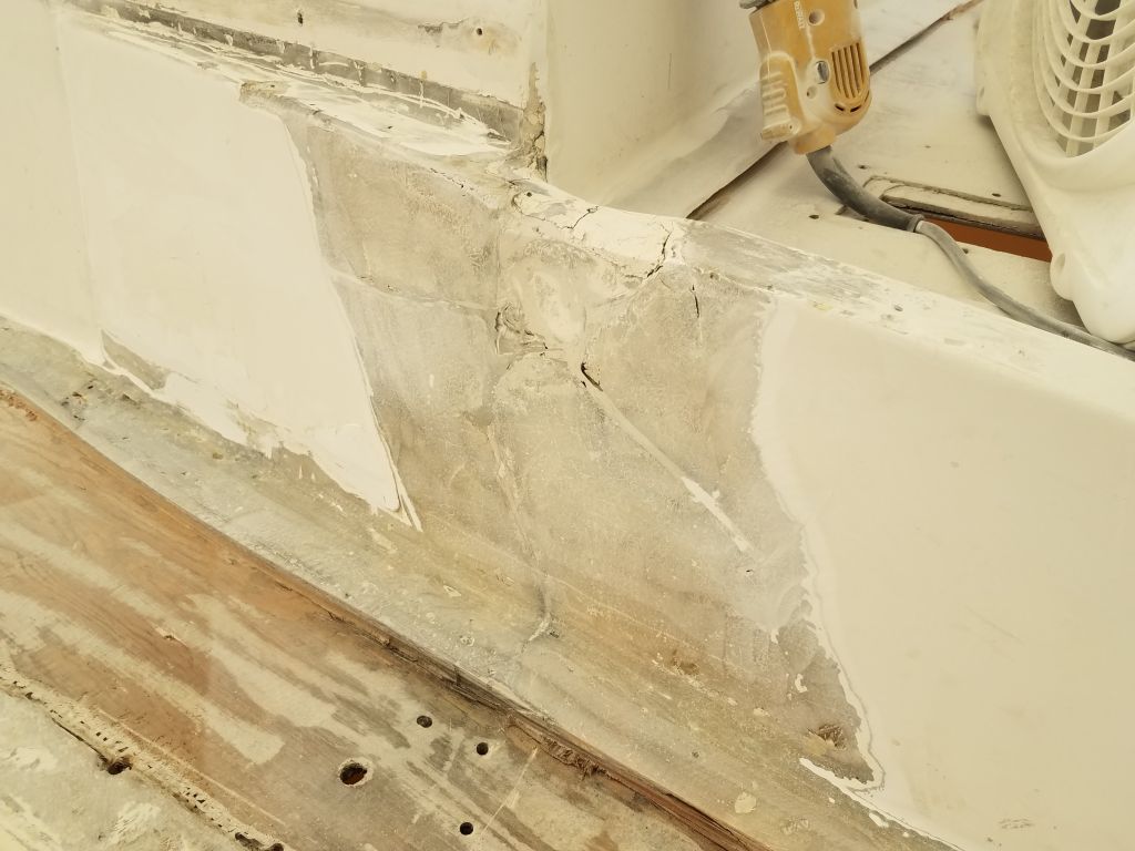
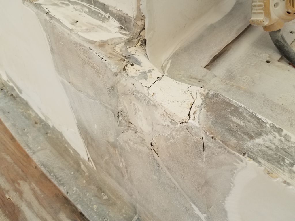
The existing inner deck skin and the transition at edge of the hull featured various voids, depressions, and rough edges, a combination of ills from previous repair efforts (including an inner skin that was tabbed to the inside of the hull below the original hull flange), damage subsequent to those repairs, and removal efforts.
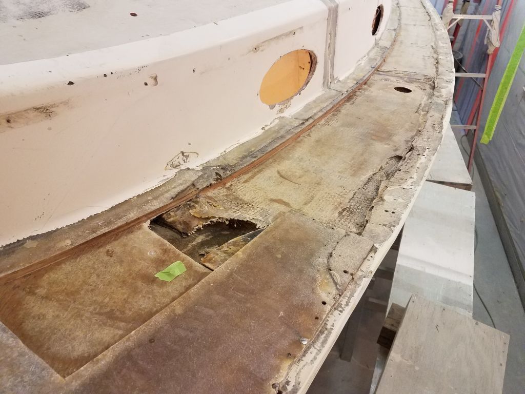
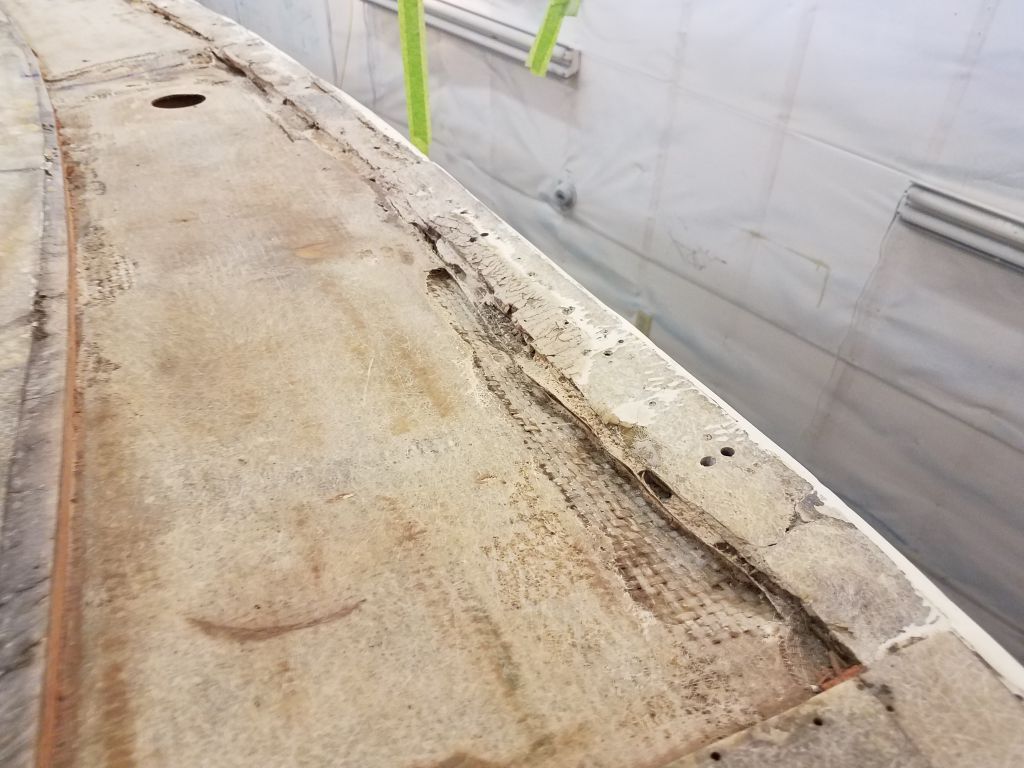
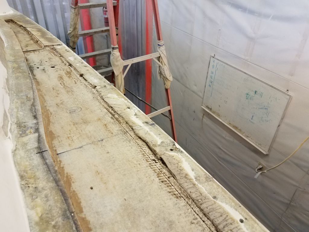
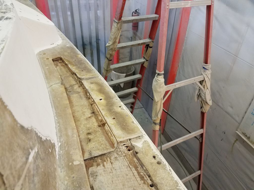
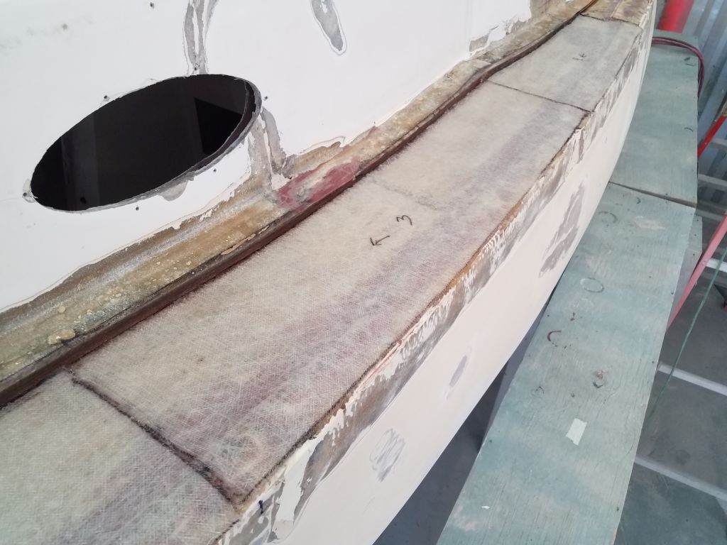
To begin to prepare this deck for new work, fill low spots, and smooth out the transitions, I applied a coat of thickened epoxy to these areas. With a bit of unused fairing compound remaining at the end, I used it to start to smooth out the old damage in the port cockpit coaming so I could fully rebuild that area later.


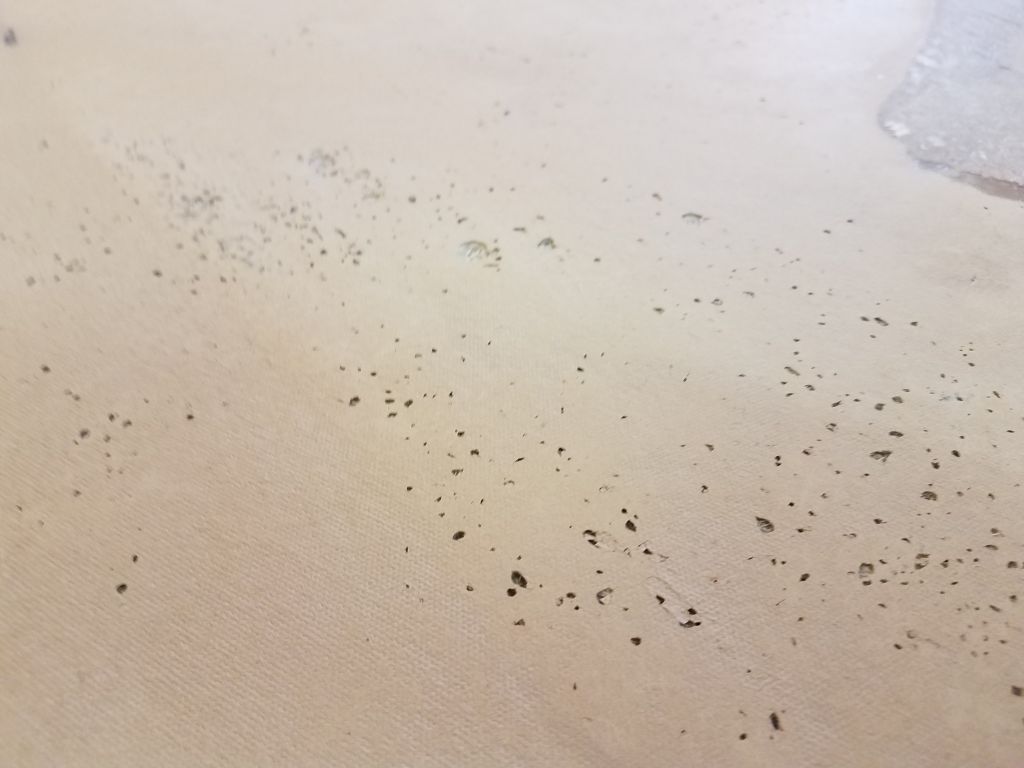
On the main decks, I went around and sanded the new fiberglass patches I’d installed last time, bringing the edges smooth and flush with the existing decks as necessary. At the same time, I did an initial sanding of the nearby deck surfaces, which featured the original gelcoat and mild nonskid pattern. With substantial new work and plenty of fairing and sanding still to come, I didn’t make an effort to fully prepare the old decks at this time, as future work–including the fiberglassing for the hull/deck joint and the fairing to go along with it–and later sanding efforts would see me going over these areas again and again. Some areas of the original deck had numerous gelcoat voids that I’d have to take care of as well, but with the existing sanding I could now start to address these issues as I worked in nearby areas in the coming days and as surface preparations continued.


Afterwards, I cleaned up and applied a first coat of epoxy fairing compound to the main deck patches.


Total time billed on this job today: 7.5 hours
0600 Weather Observation: 45°, clouds and fog. Forecast for the day: Clouds and showers, 40s
Monday
I finished up the patterning for the various top-skin deck repairs in the cockpit, following the same process I’d done on the main decks earlier.
I spent the rest of the morning cutting three layers of 1708 biaxial fabric for each patch.


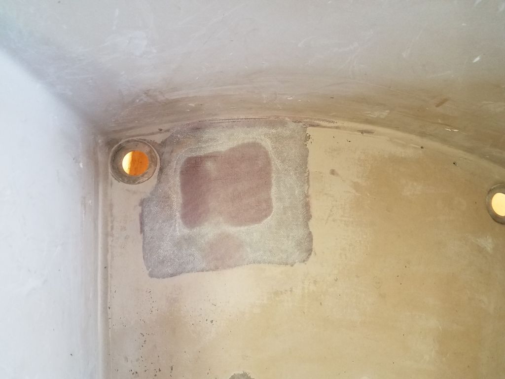
During the afternoon, I began by filling various small voids and holes in the exposed plywood core with a thickened epoxy mixture, and also pre-wetting the core and surrounding areas with epoxy to prepare for the new laminate. For now I focused only on the main decks, leaving the cockpit for another session.
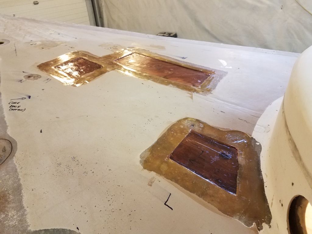
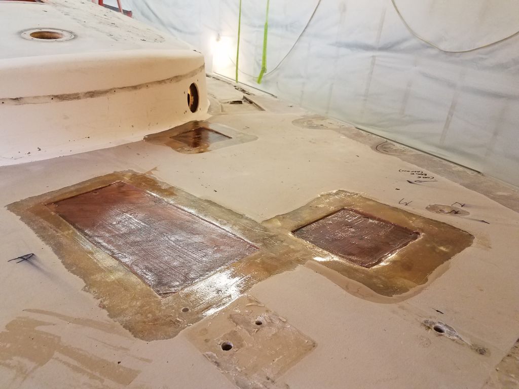

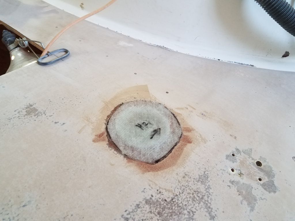
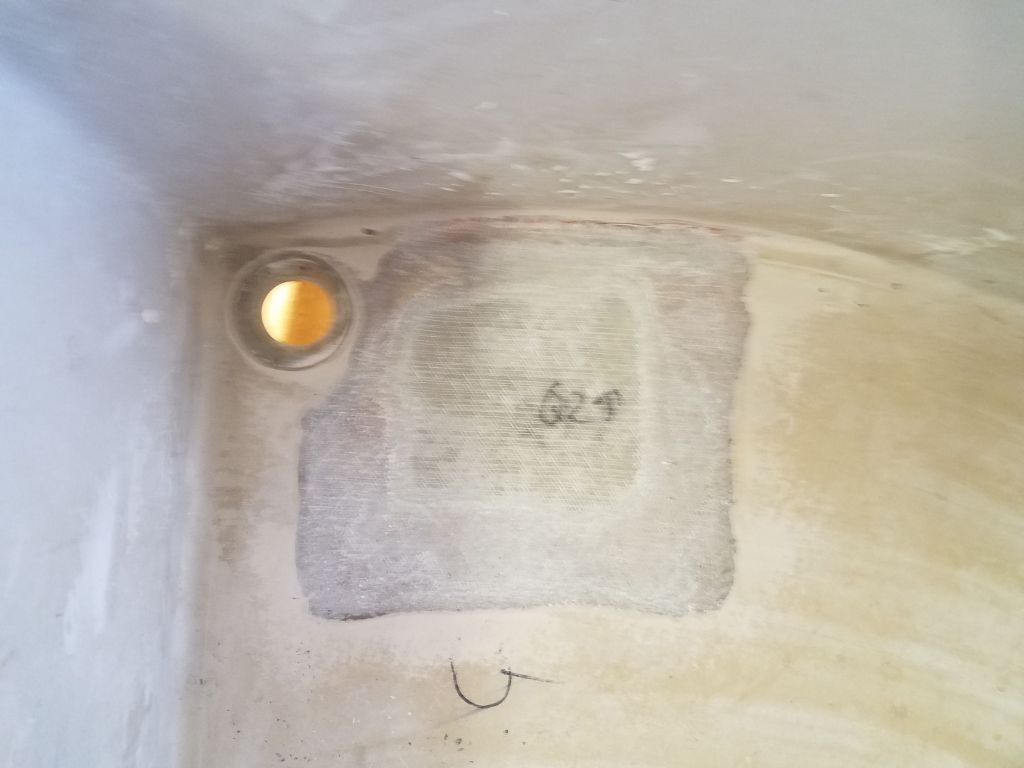
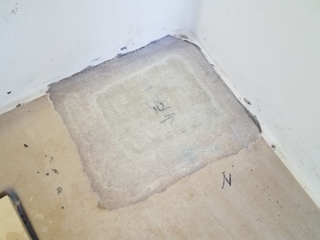
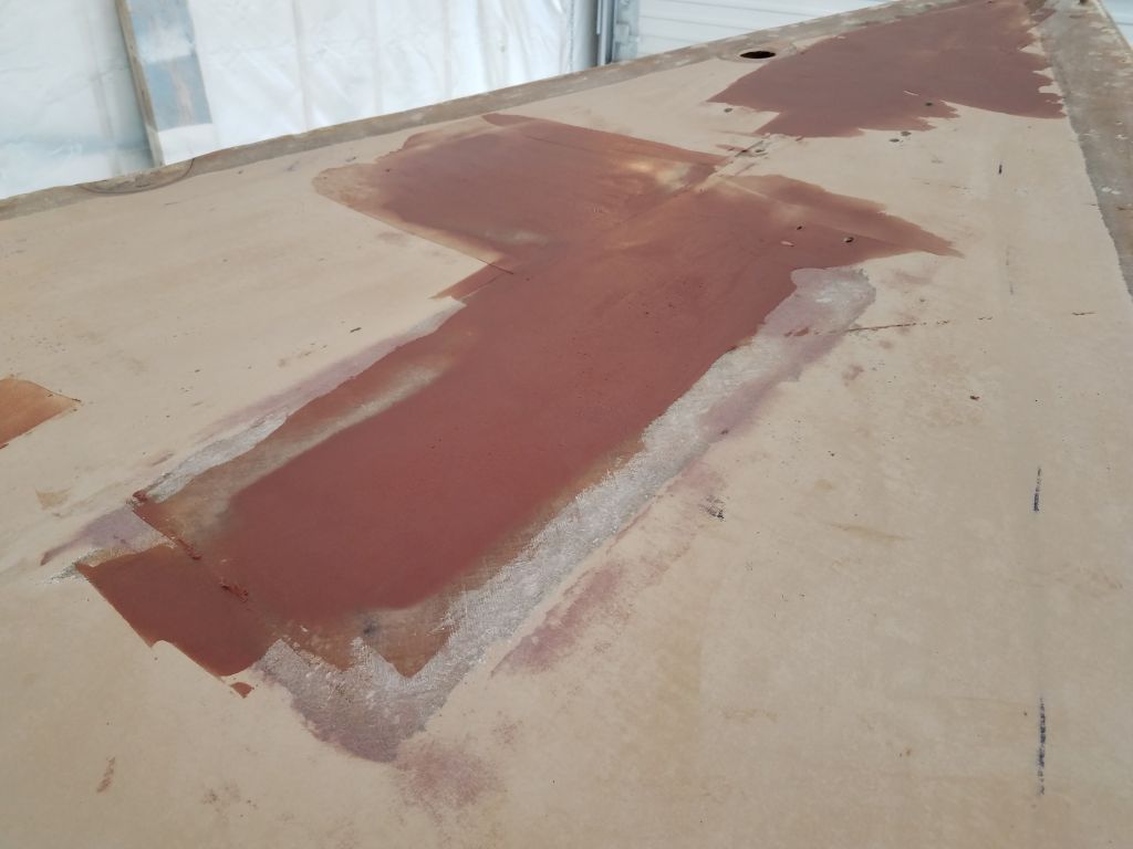
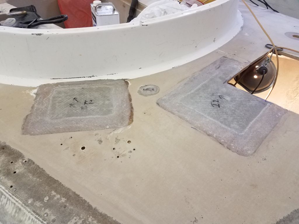
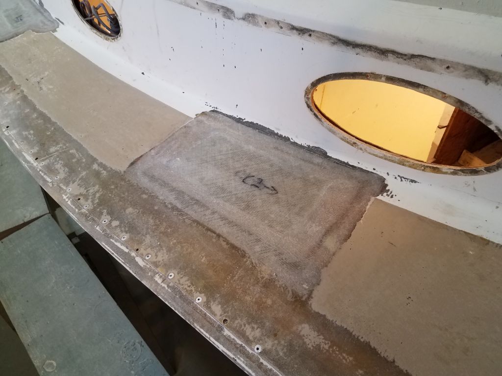
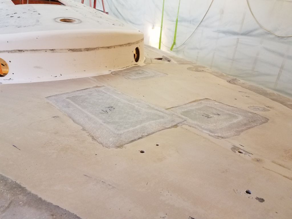
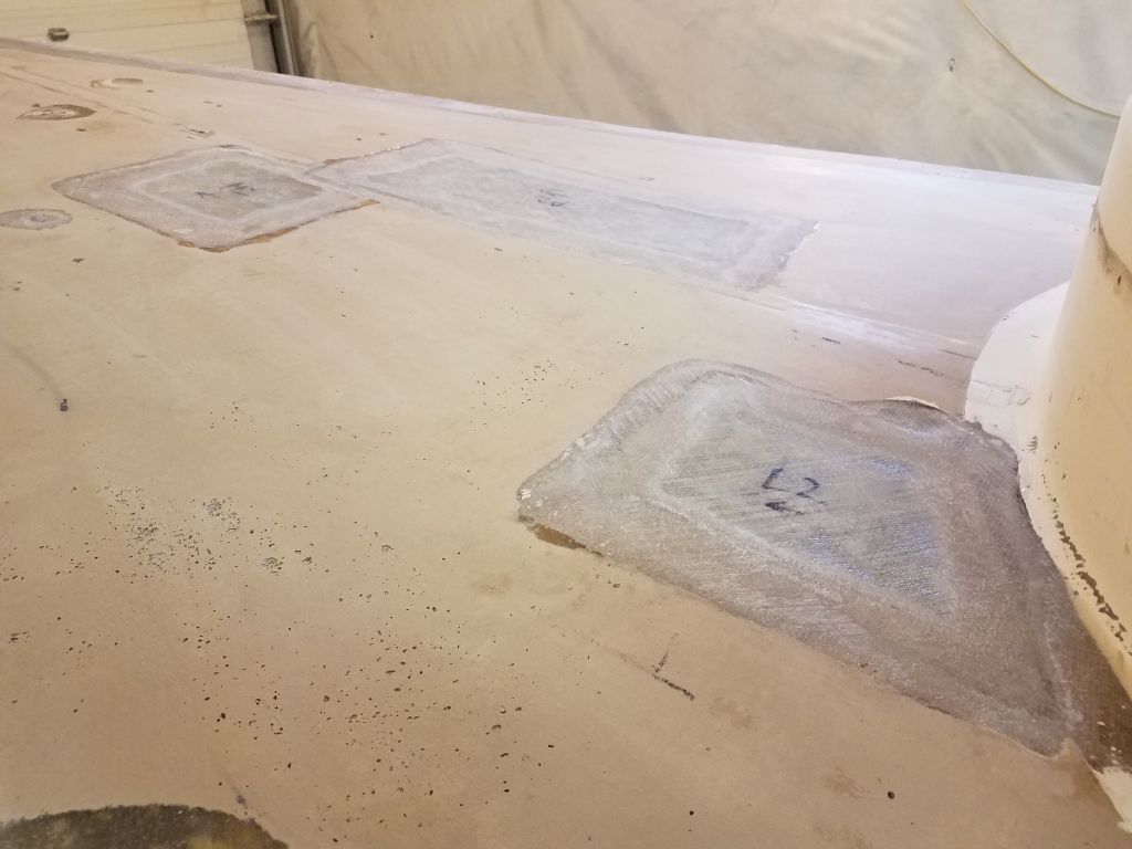
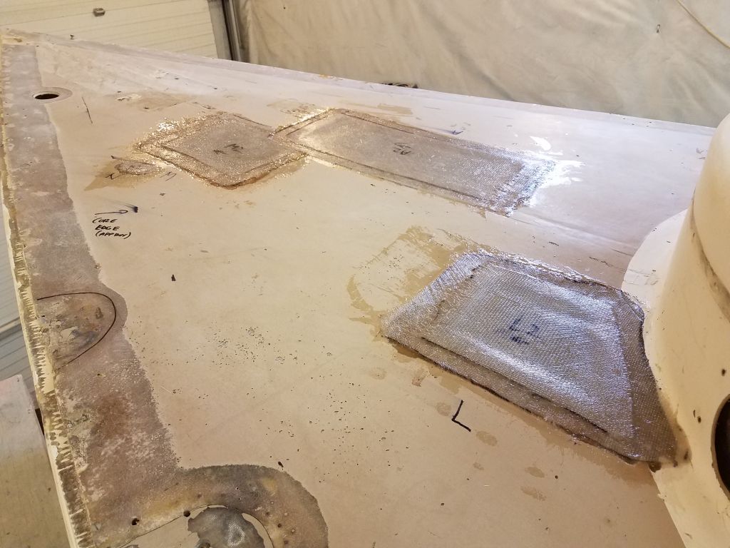
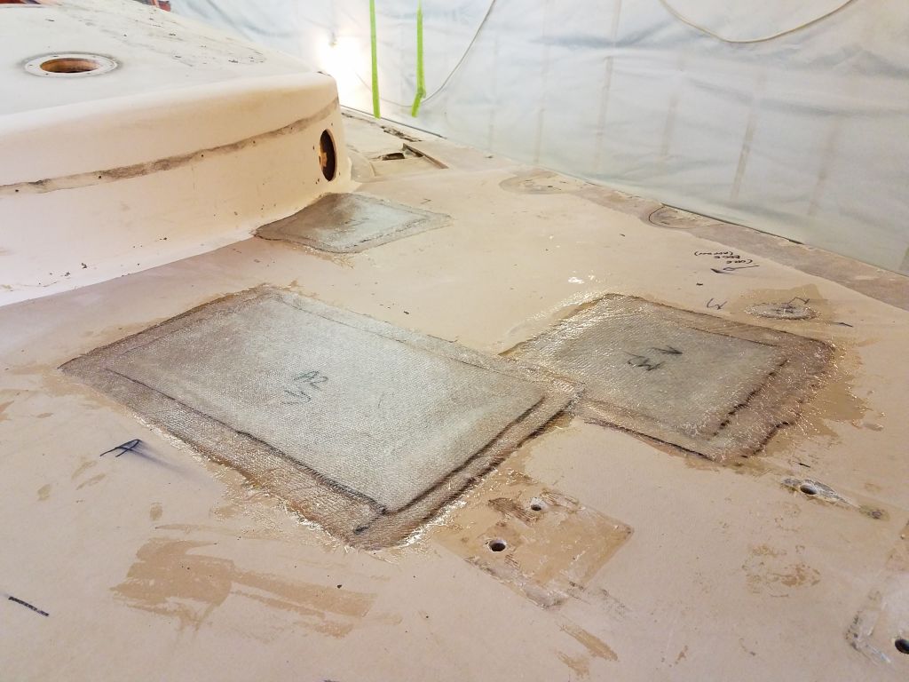
At each location on the main decks, I installed a layer of 1708 cut to fit directly over the core, bringing the center of each opening up roughly flush with the adjacent deck surfaces that I’d prepared earlier, and used additional slightly-thickened epoxy to smooth the edges for the next steps.

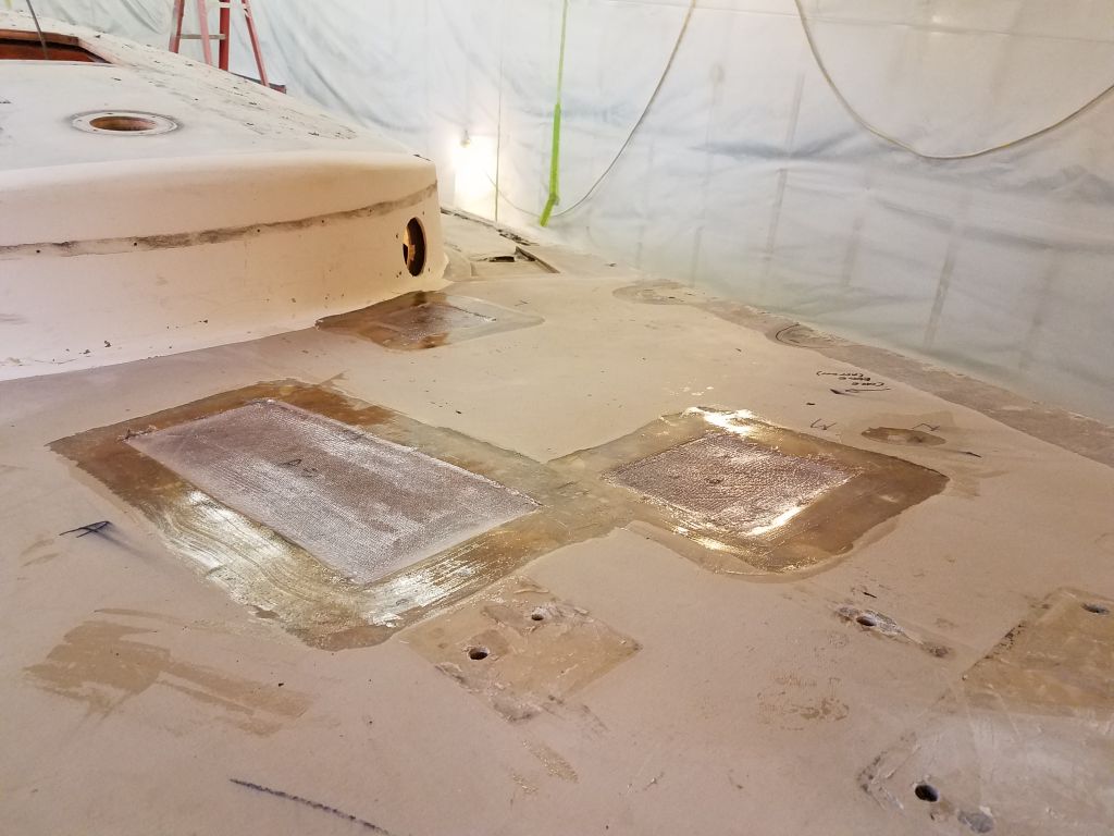
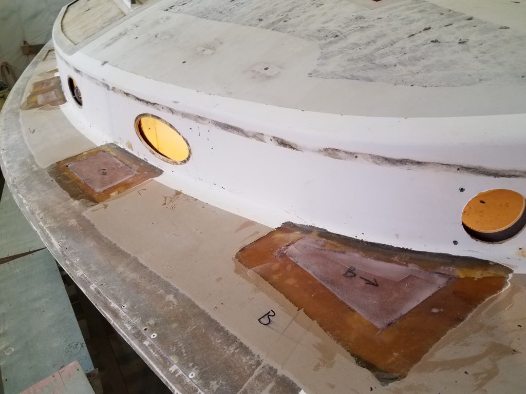
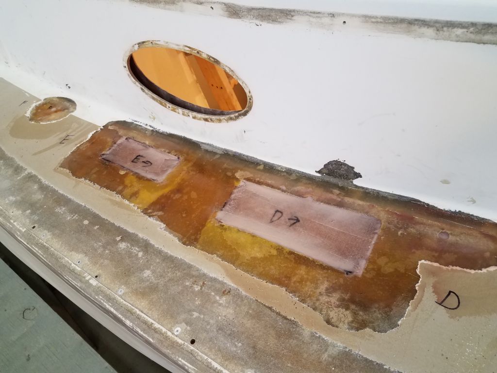
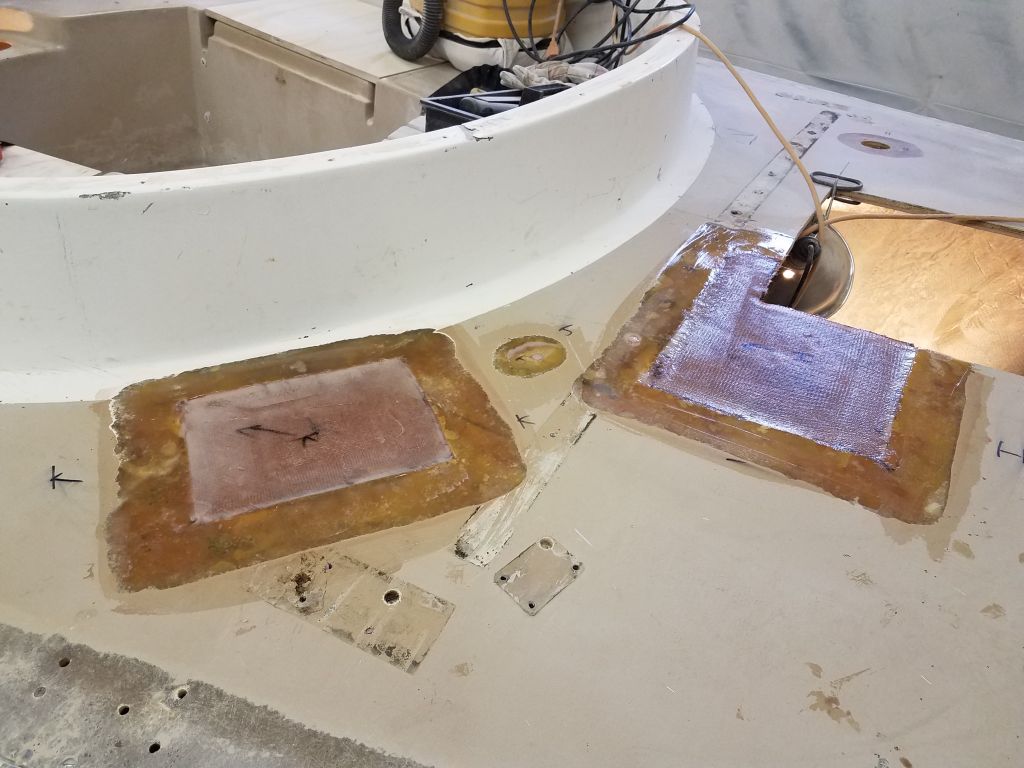
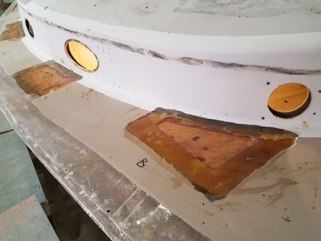
Finally, I installed two layers of the 1708 in epoxy resin over each section. The final layers overlapped the adjacent decks by a couple inches on all sides and tied the new work in with the existing laminate.

Total time billed on this job today: 7.25 hours
0600 Weather Observation: 31°, light sleet/freezing rain. Forecast for the day: Sleet and freezing rain eventually changing to rain, then heavy rain overnight, 38°
Friday
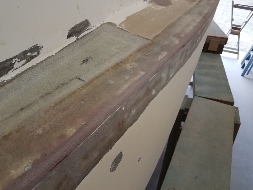
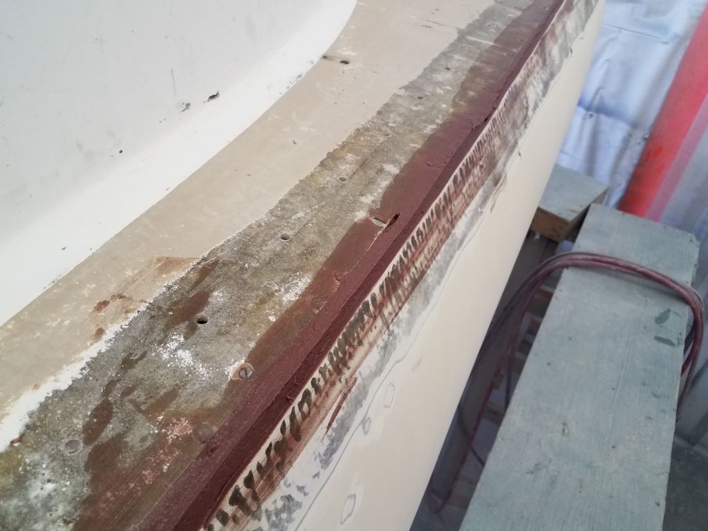
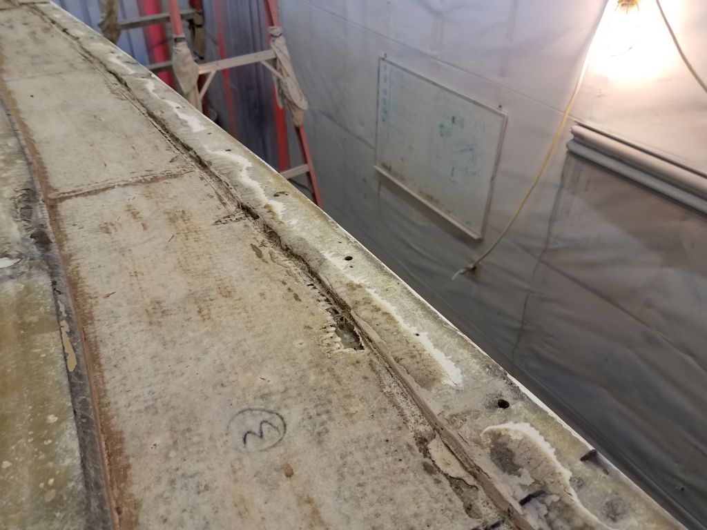
Picking up where I left off, I continued work on the hull/deck joint preparation, working my way past the starboard quarter and across the transom.


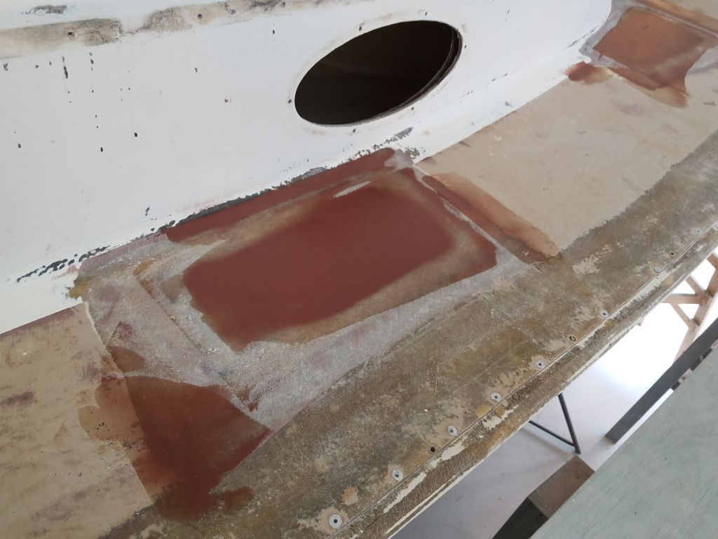
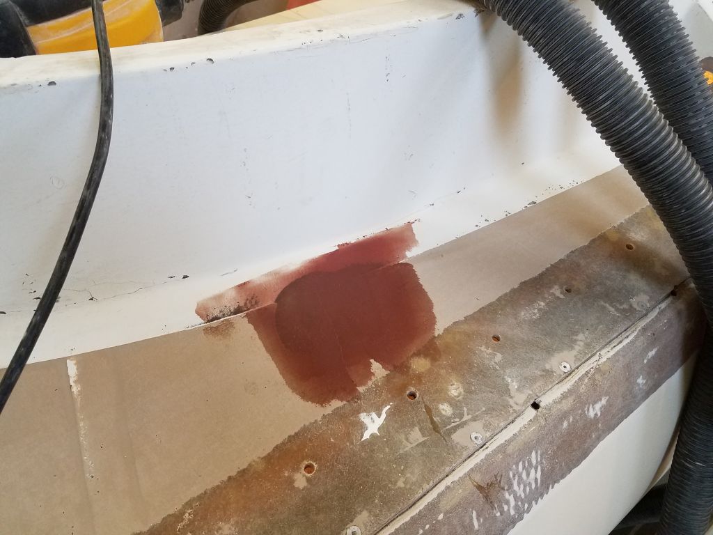
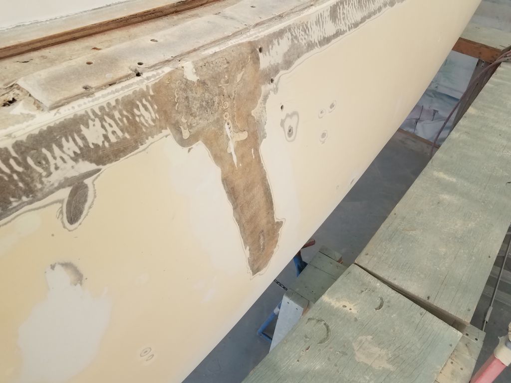
At the same time, I more thoroughly prepared an area on the port hull where some previous repair work had been, grinding out some suspect fairing compound and otherwise preparing the area for fiberglass reinforcement and refairing.
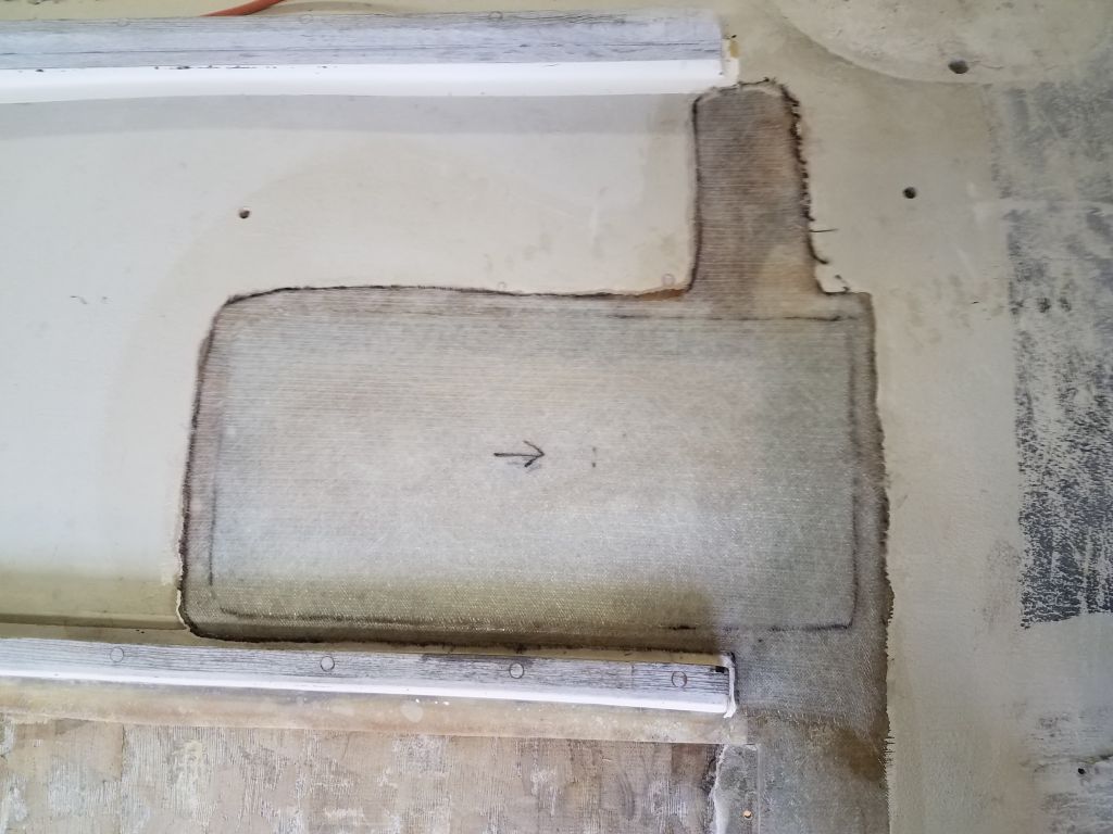
Though I’d been cleaning up incrementally throughout the week, the heavy sanding work had made a mess of the boat and shop, and while there’d be plenty more sanding to go as time went on, for the moment I was done and planned to focus on getting the decks put back together, so I spent some time giving the shop and boat a good cleanup. While I was at it, I went over the newly un-cored areas to ream out any final bits of core from beneath the deck edges and used an air nozzle to blow out the voids and help prepare these areas for new work. It was perfect timing for all this since for once the weather outside was door-worthy and pleasant for airing out the shop.


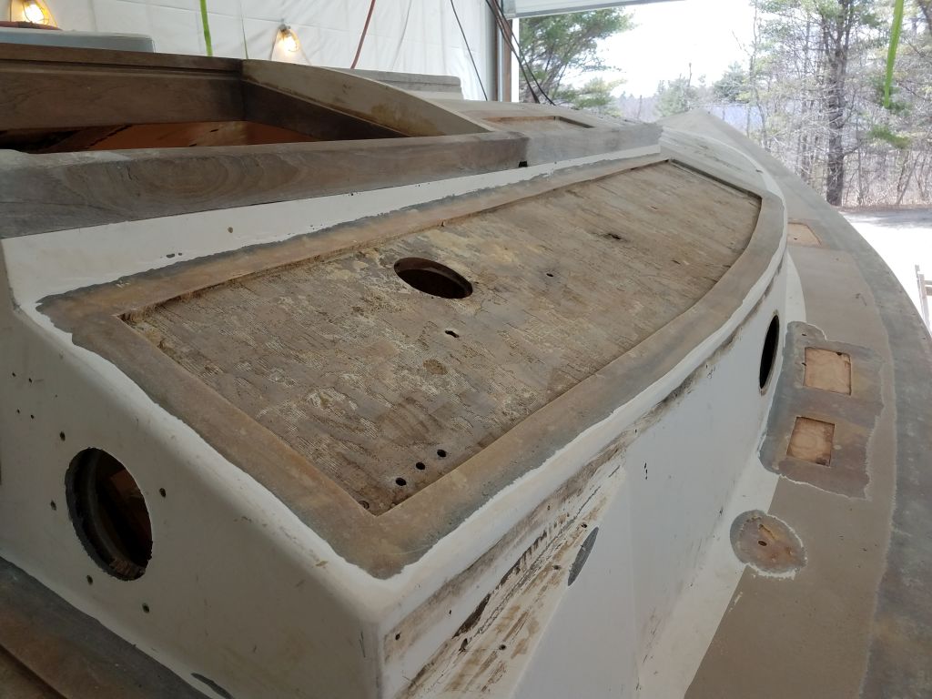
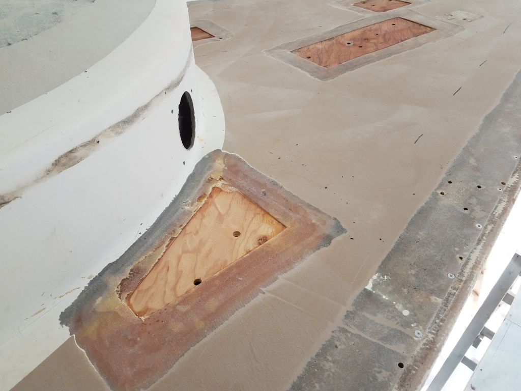
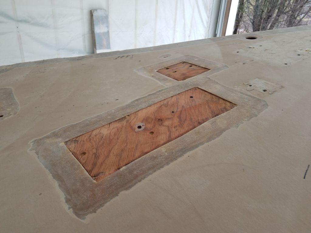
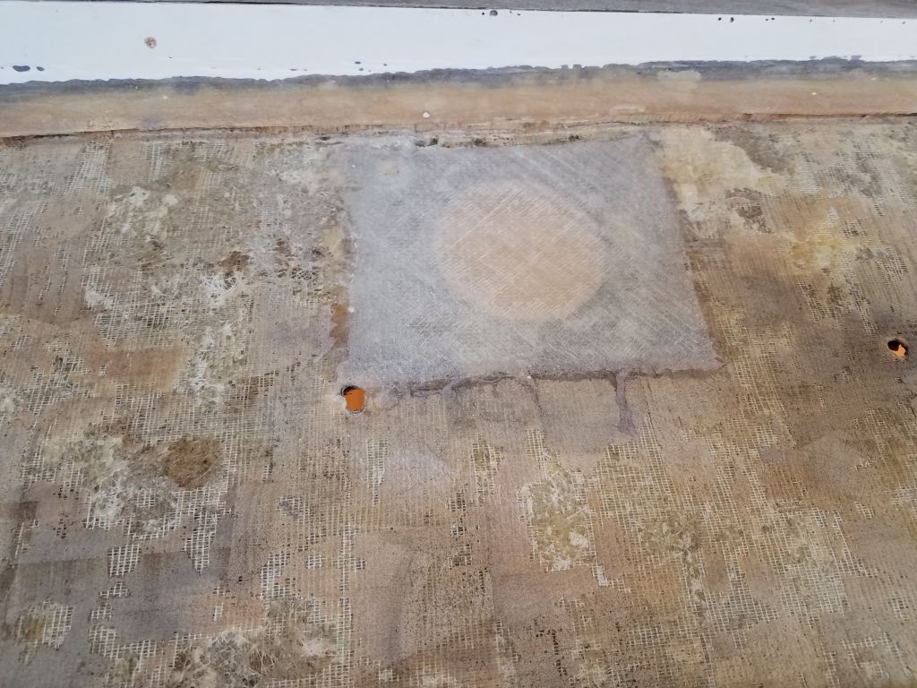
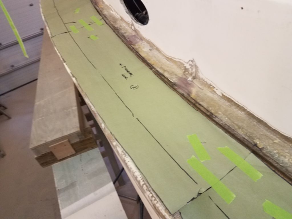
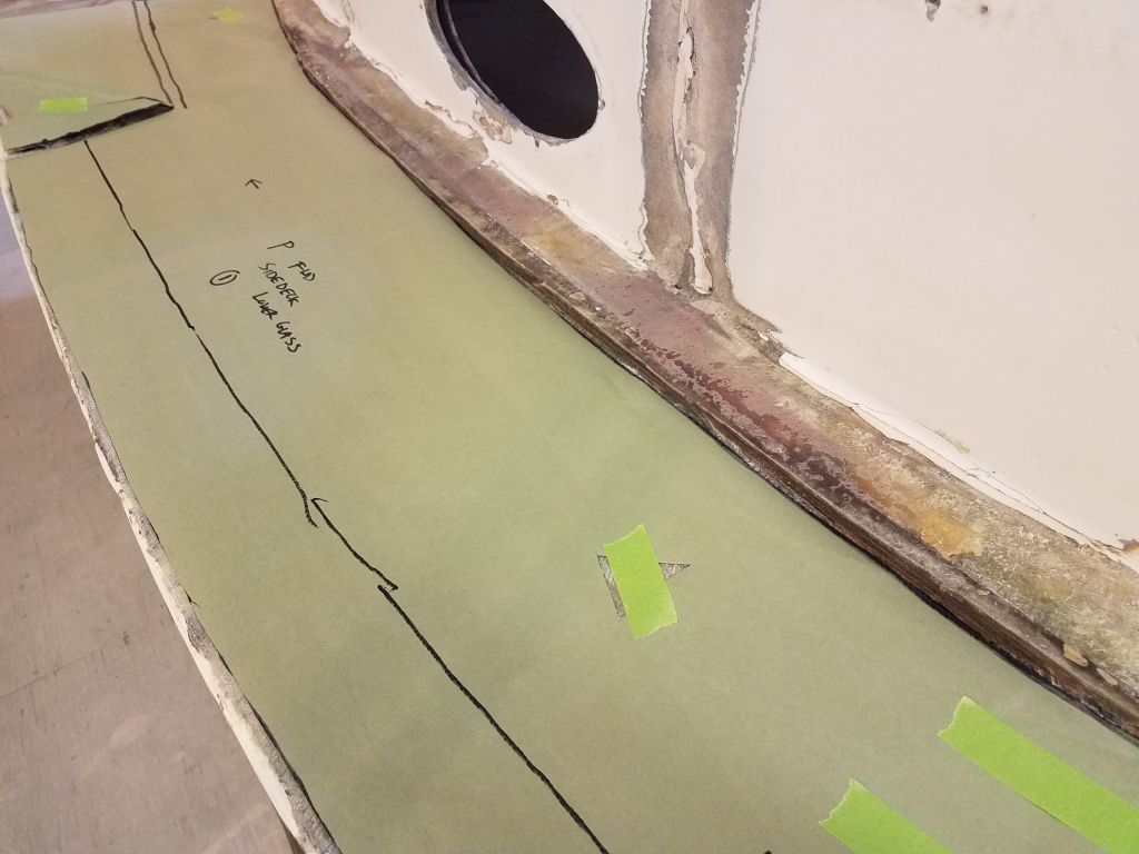
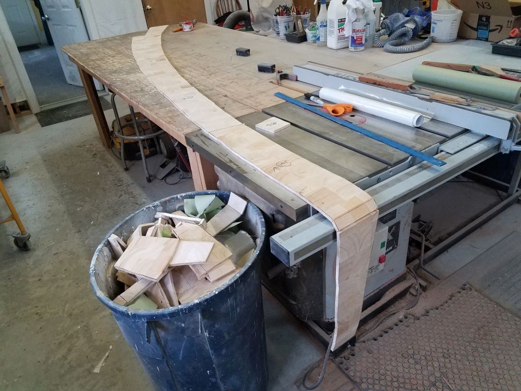
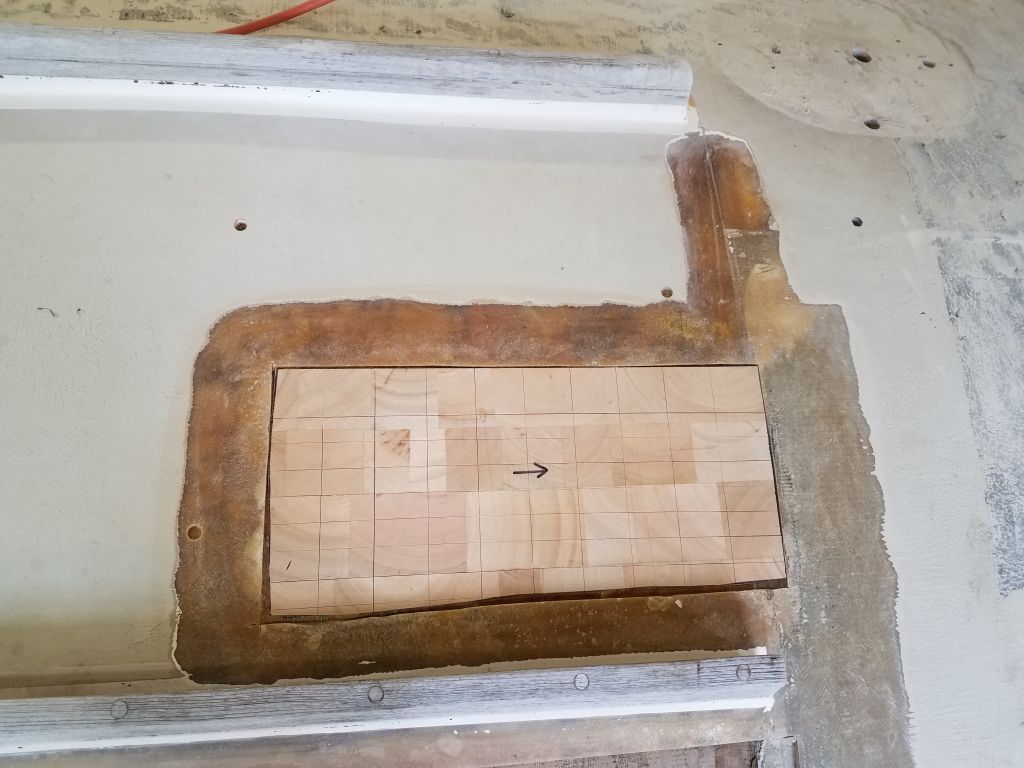
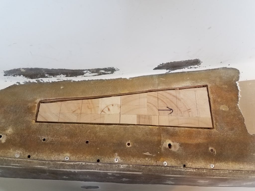
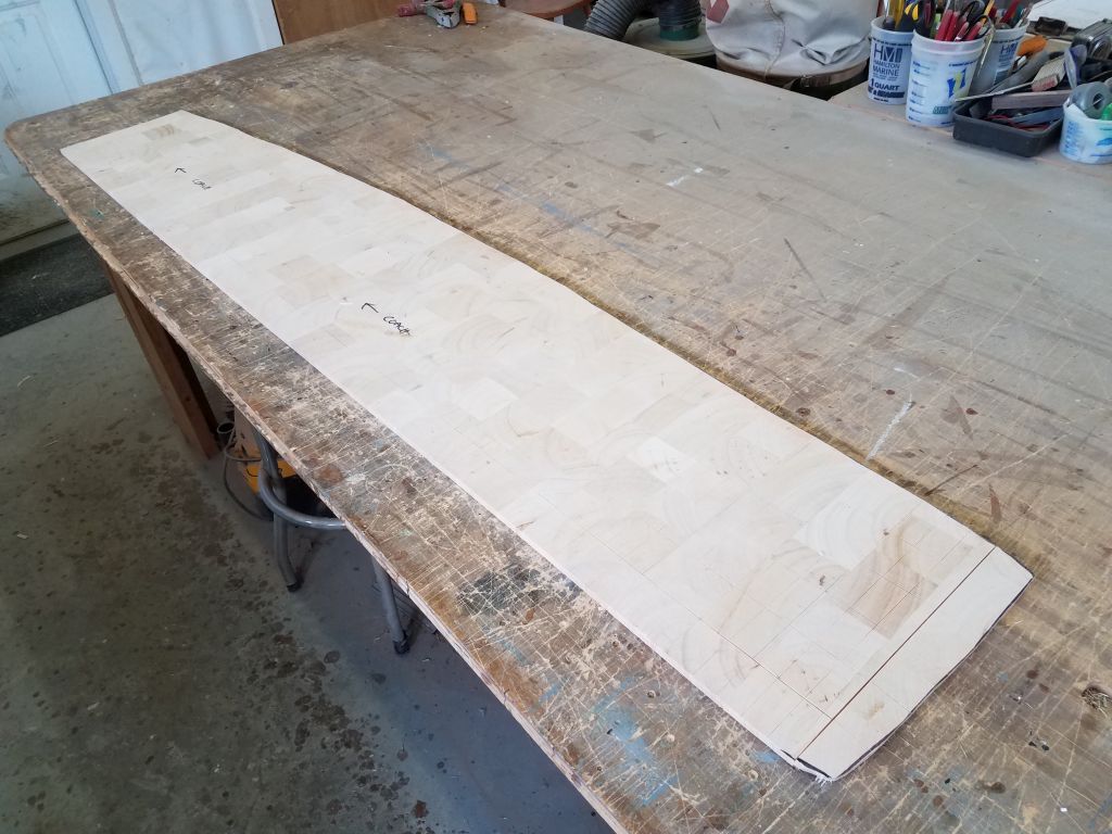
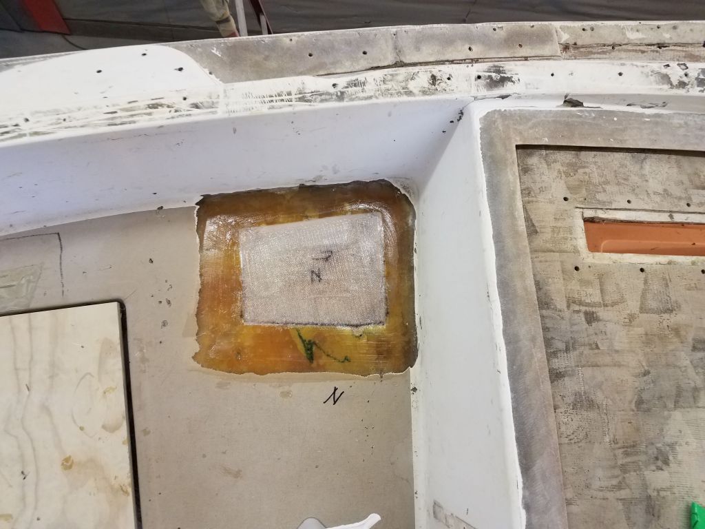
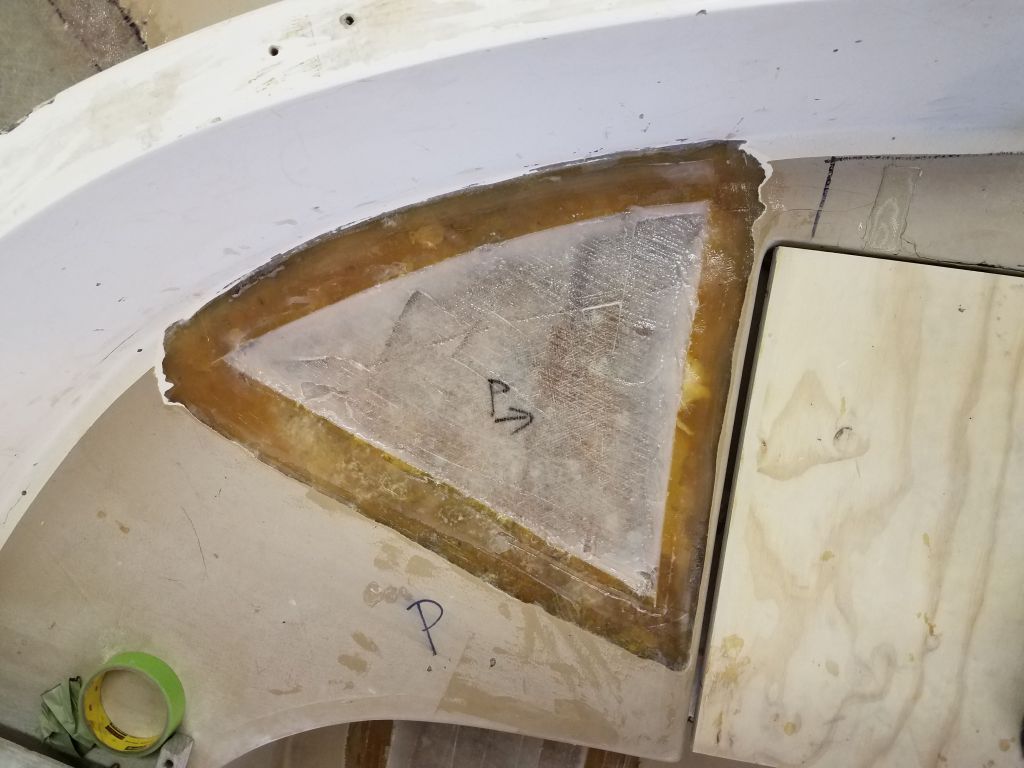
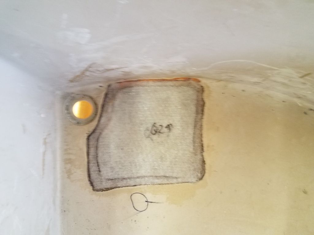
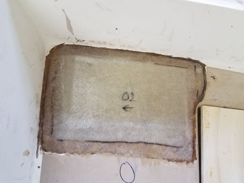
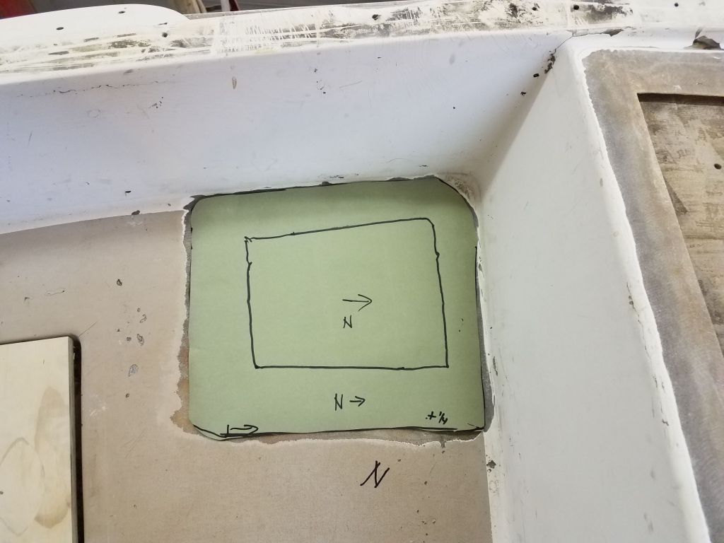
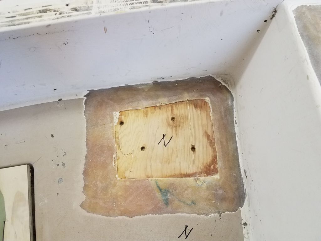
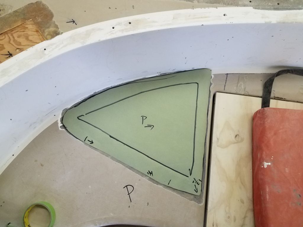
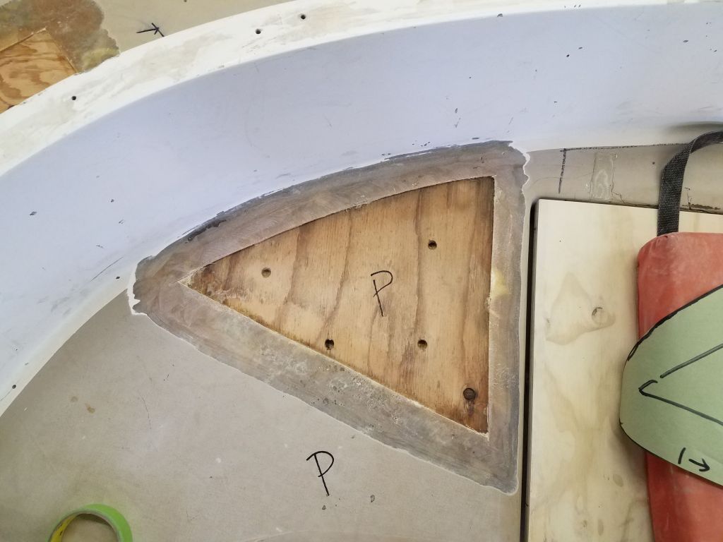
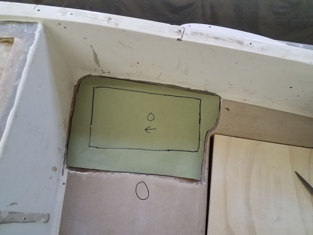
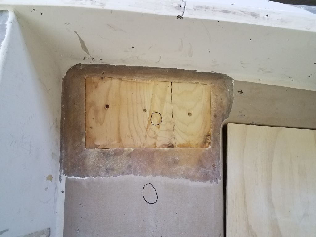
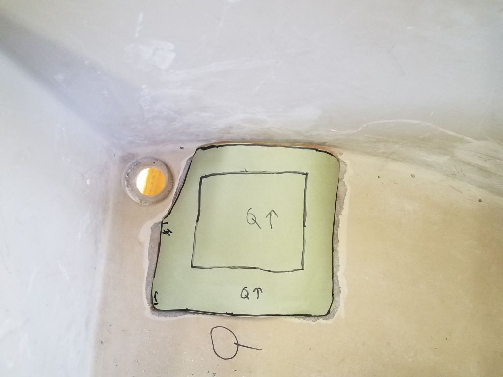
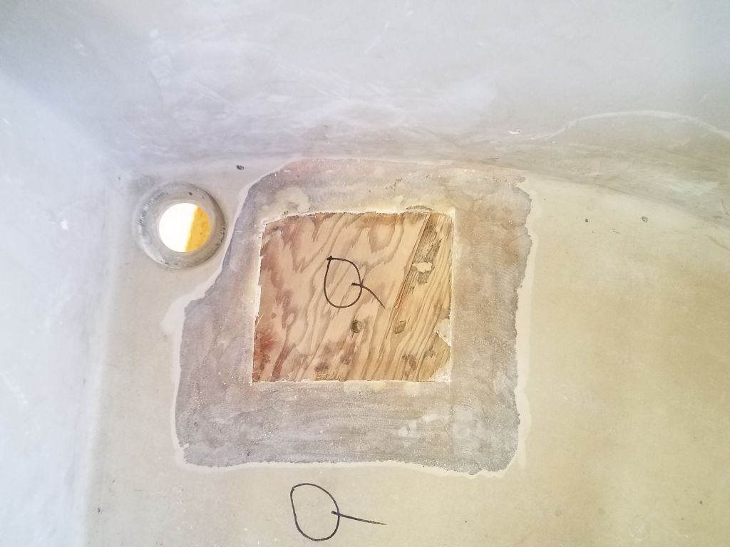
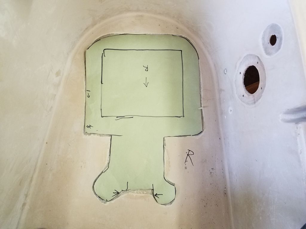
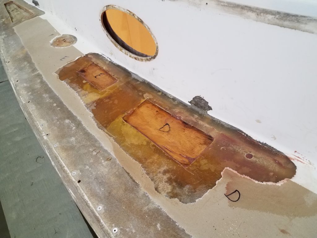
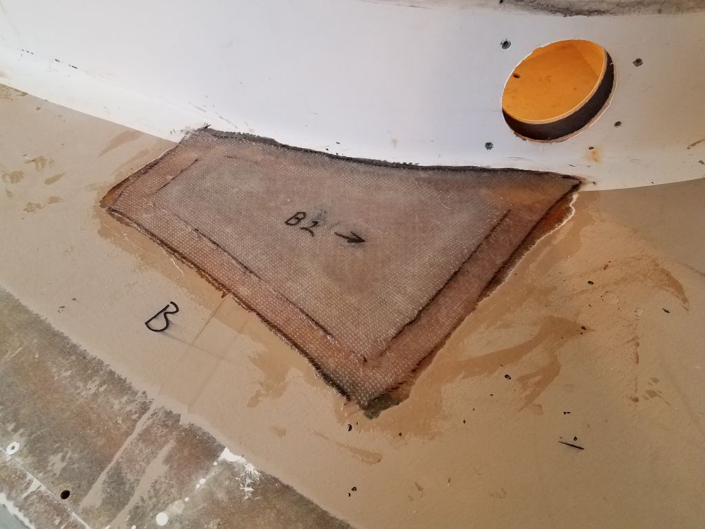
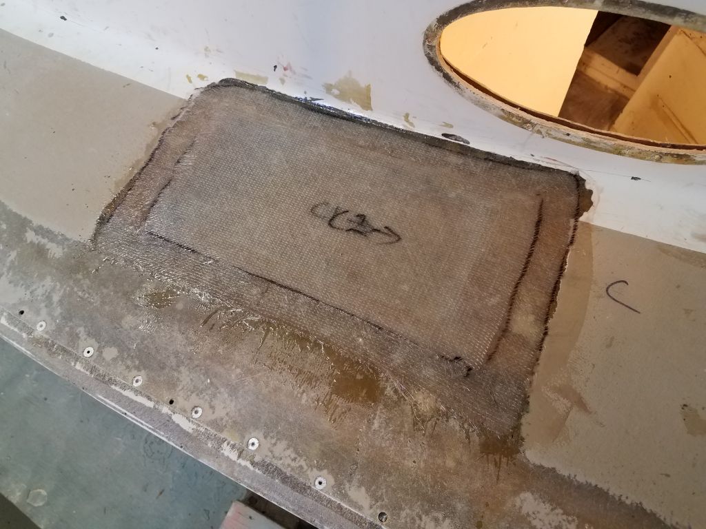
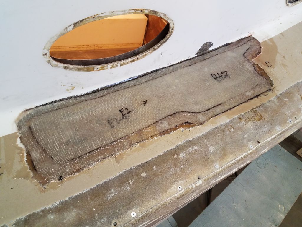
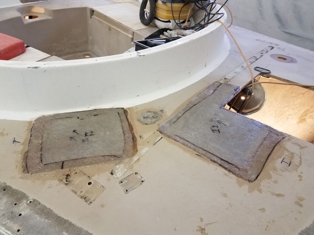
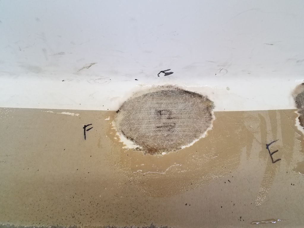
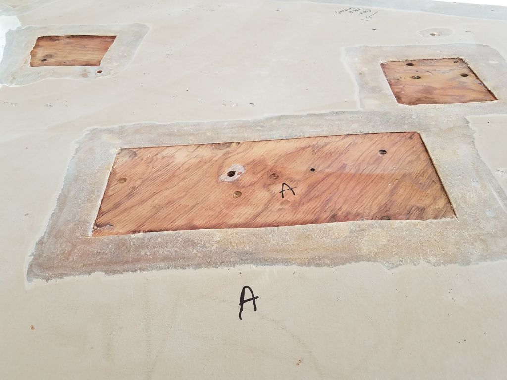
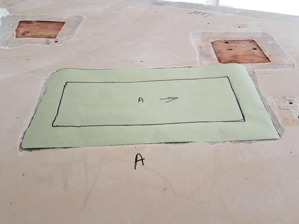
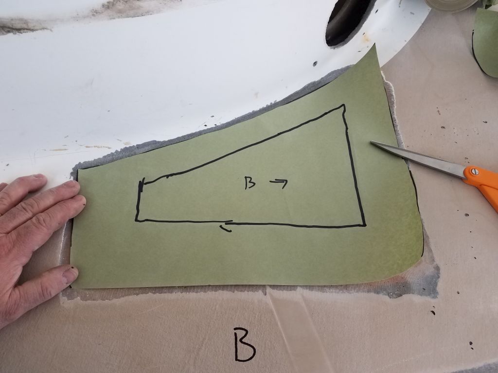
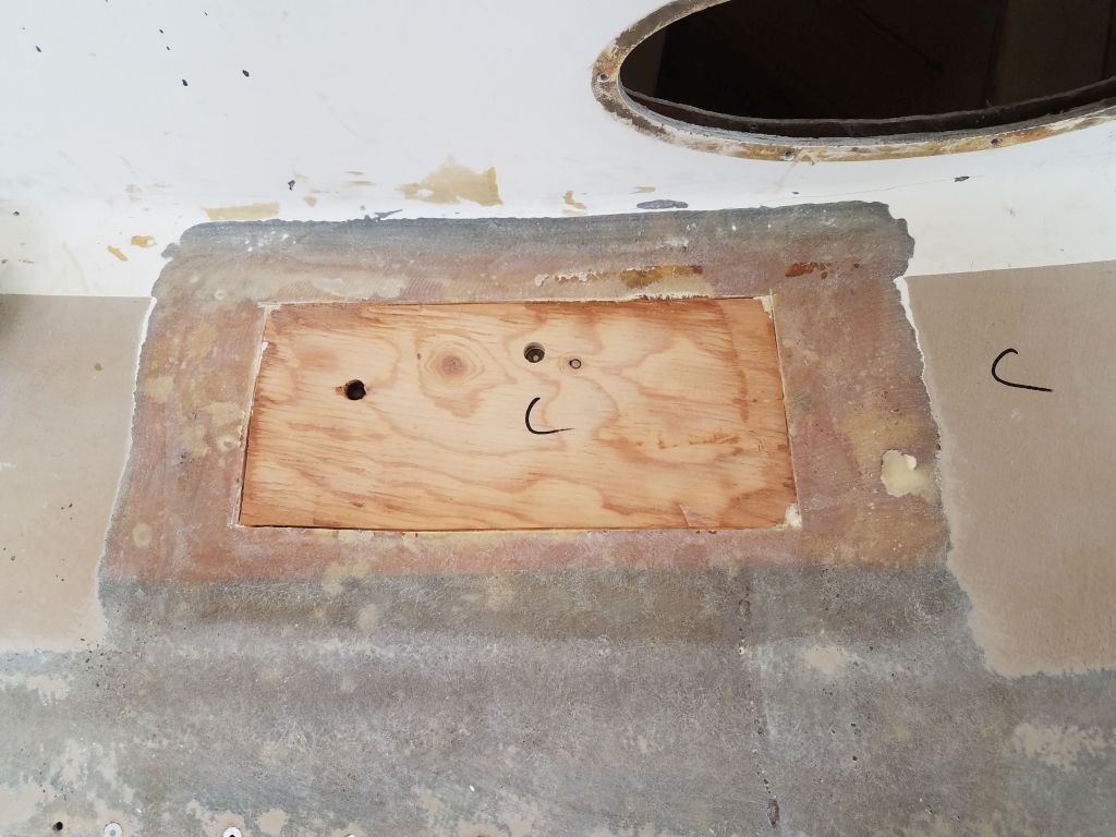
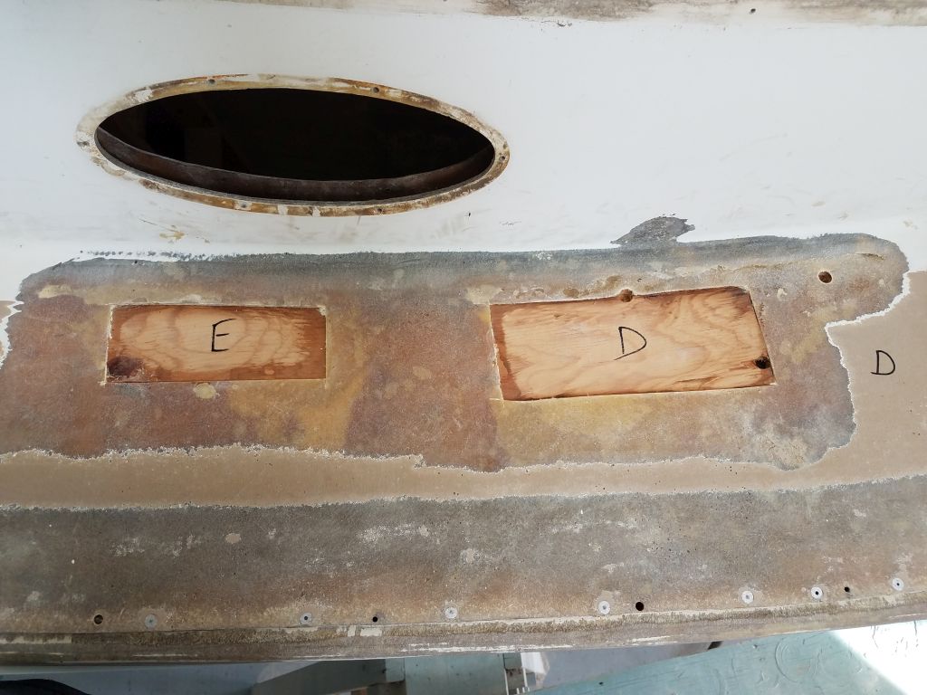
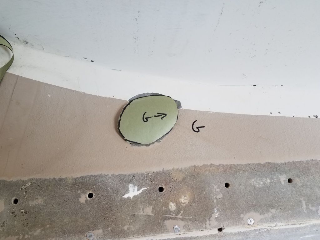
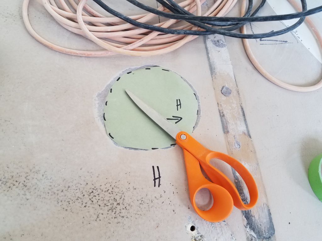
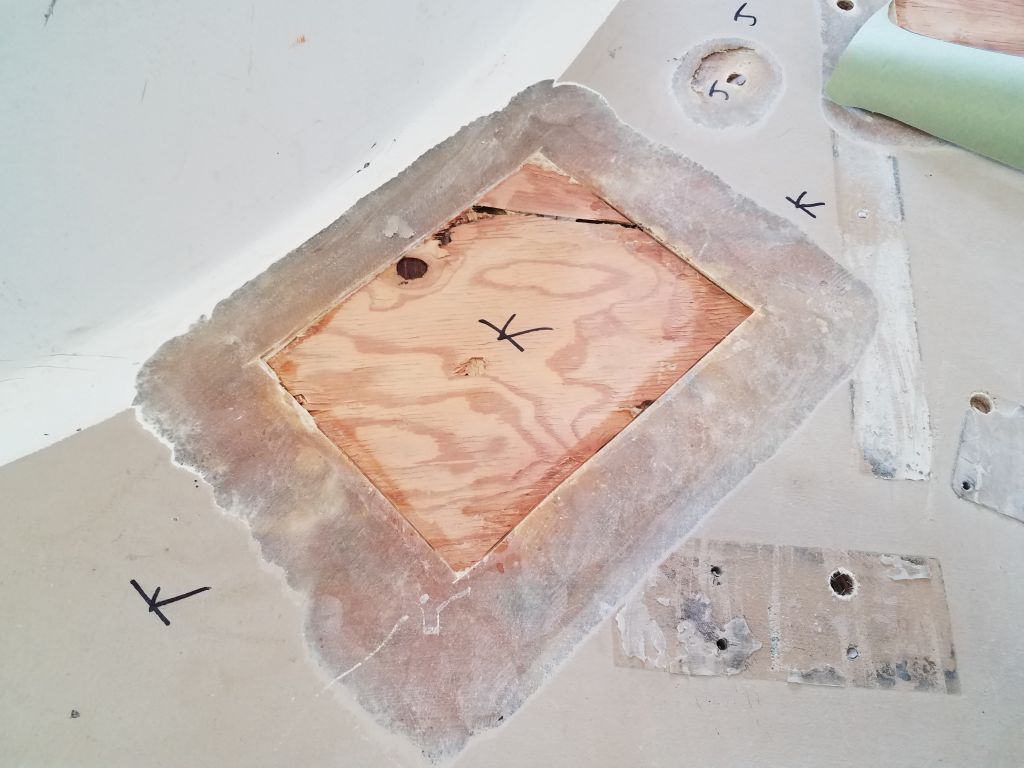
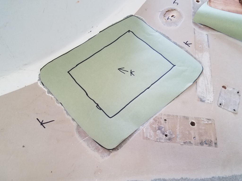
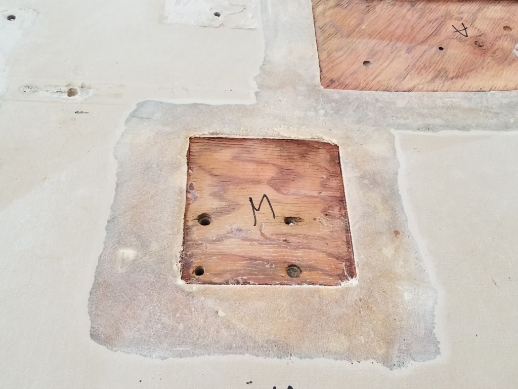
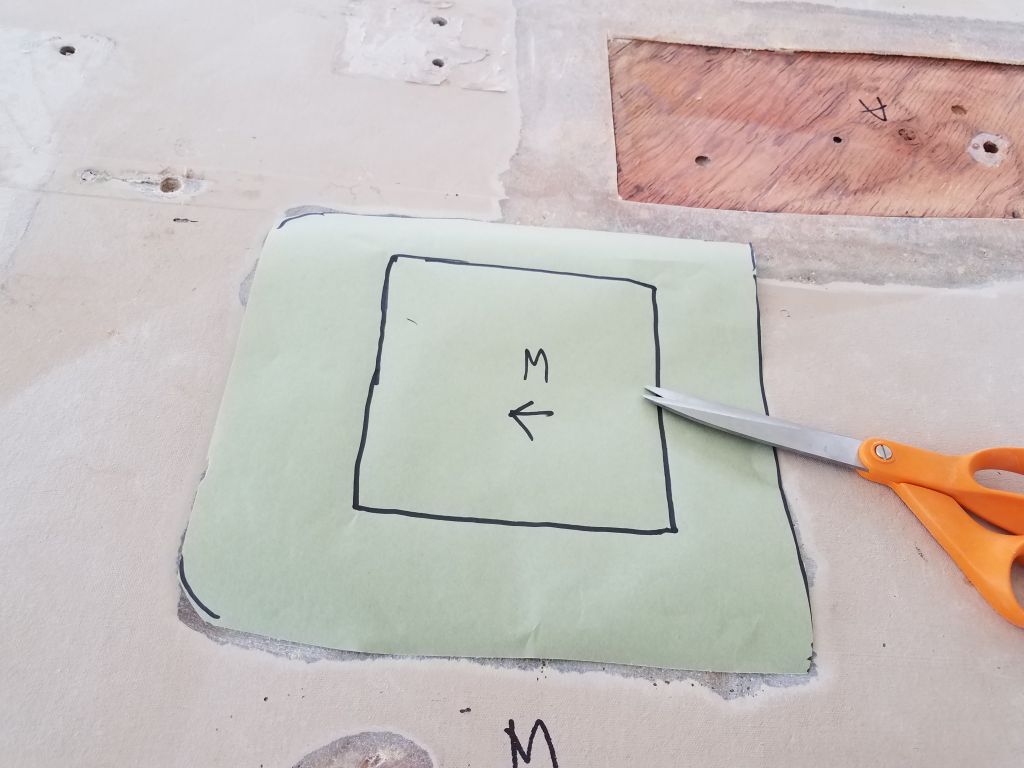
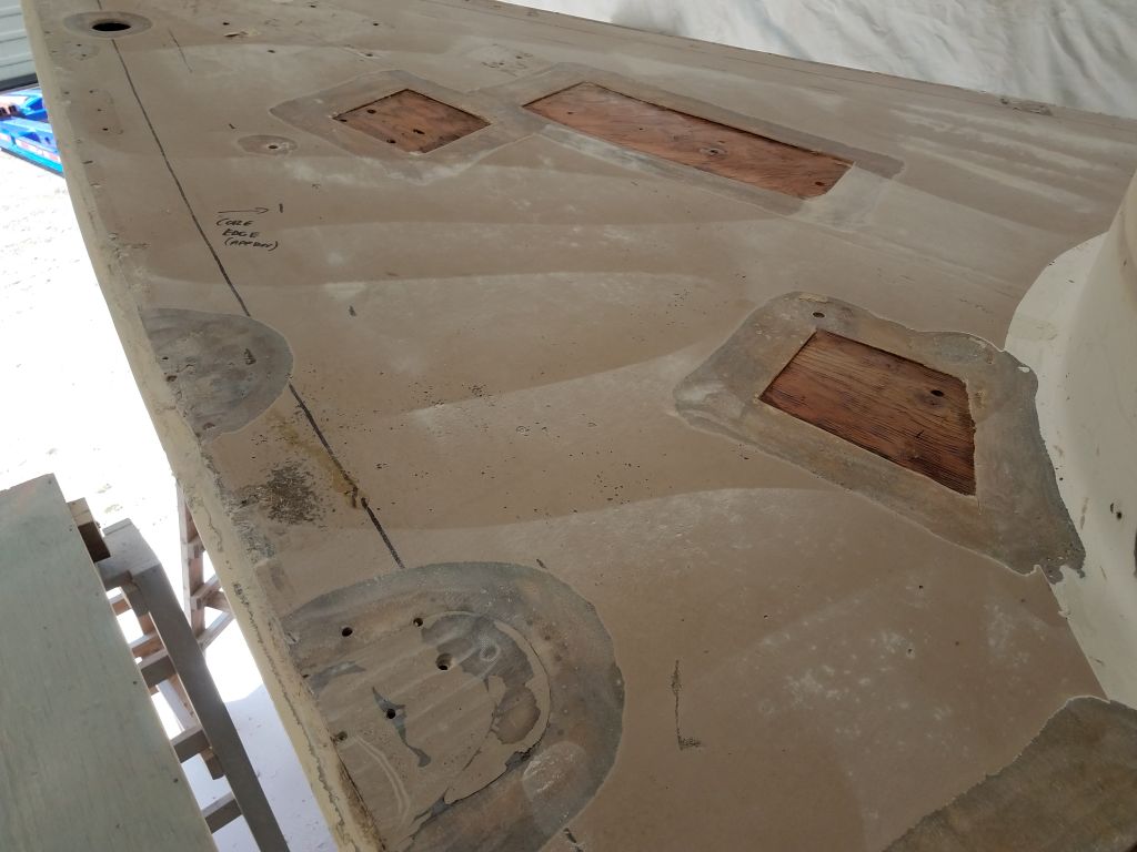
Later, I went around and made simple paper patterns of all the areas on the main decks that required relamination. As the simplest of the repairs to come, I chose to make these the first on the list; plus, having the main decks closed up again and sound would make it easier to work on the coachroof and other areas. The outside of the pattern represented the largest piece of new fiberglass, which would extend to the outer reaches of the prepared areas on the adjacent decks, and the marked regions int he centers of each pattern represented the size of the deck opening itself, as I thought I might start with a layer of fiberglass directly over the exposed core so the subsequent layers would end up more flush in the end.


Total time billed on this job today: 5.25 hours
0600 Weather Observation: 40°, overcast. Forecast for the day: Becoming mainly sunny, approaching 60°
Thursday
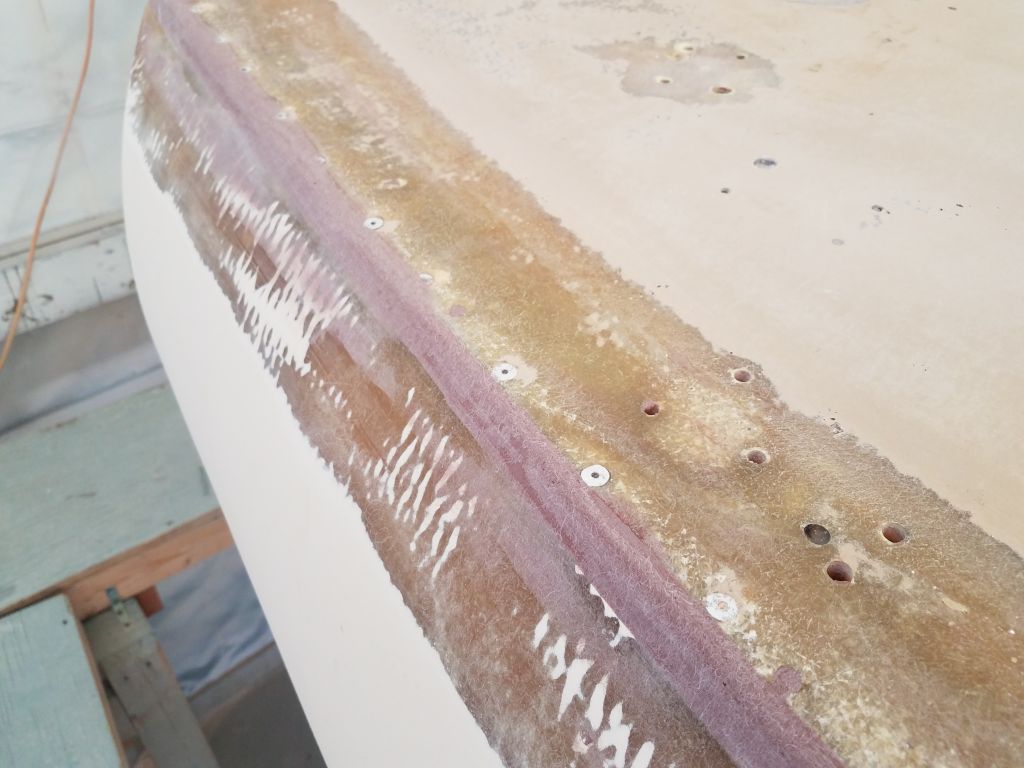
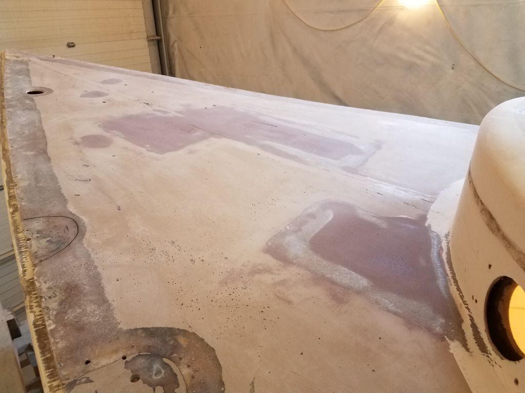
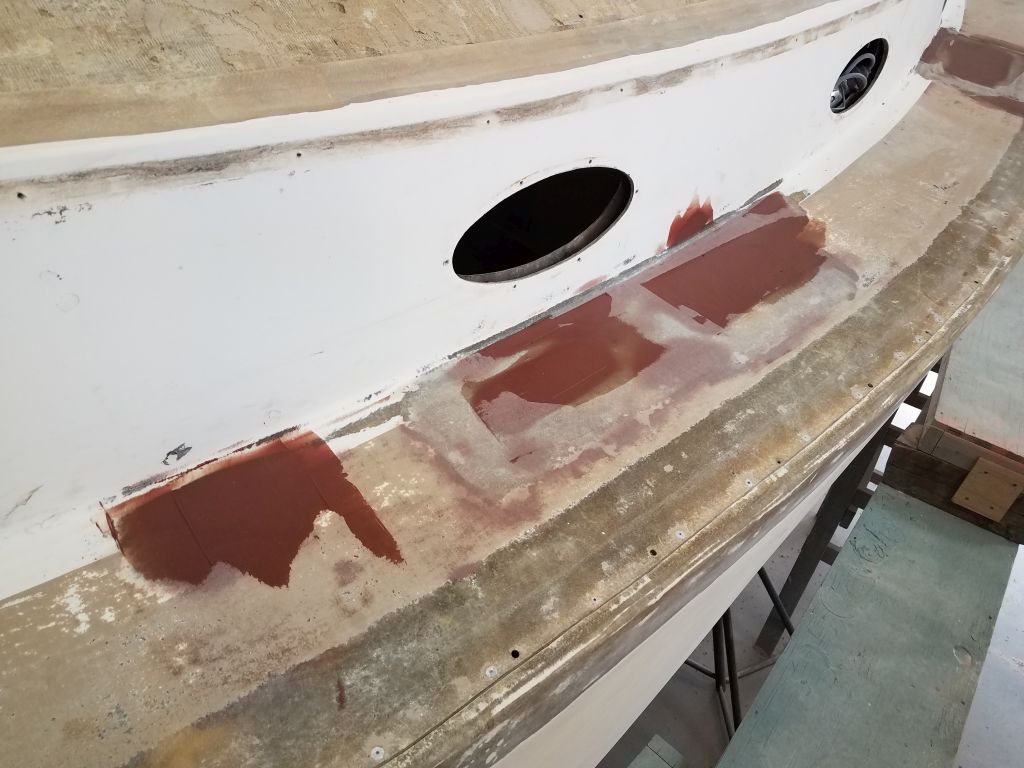
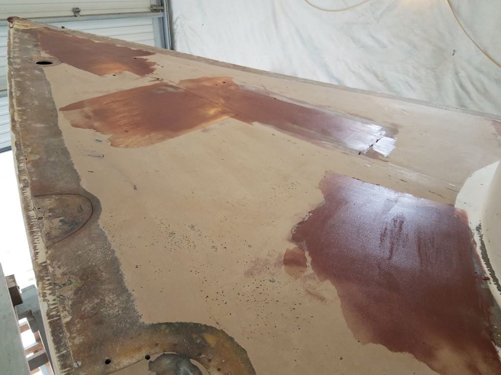
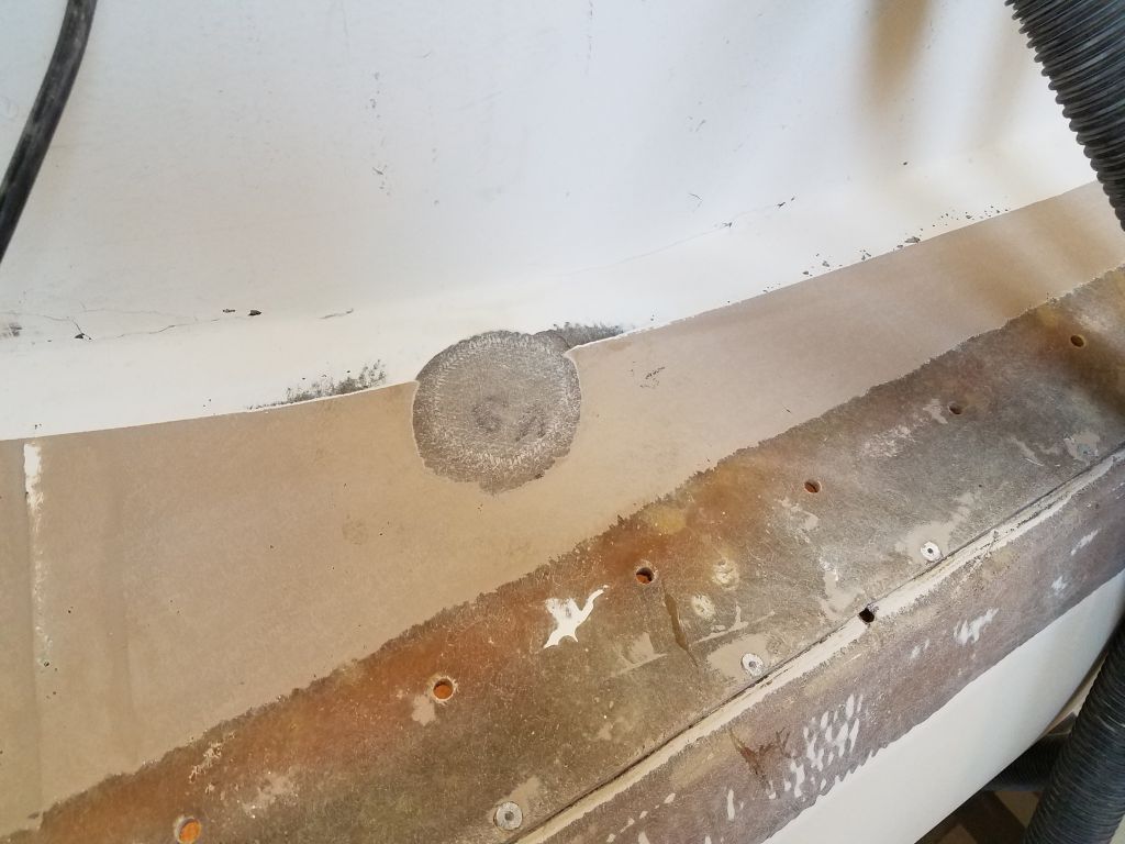
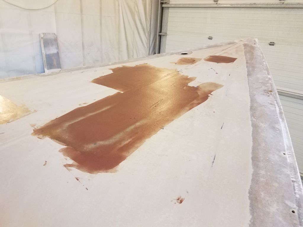
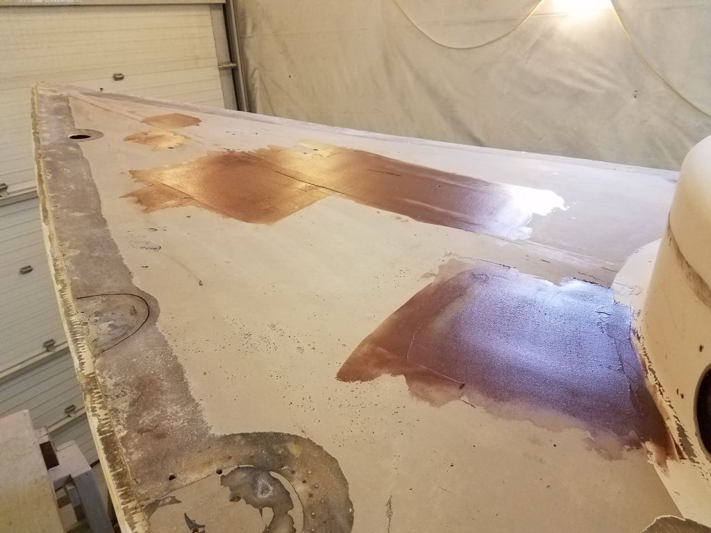
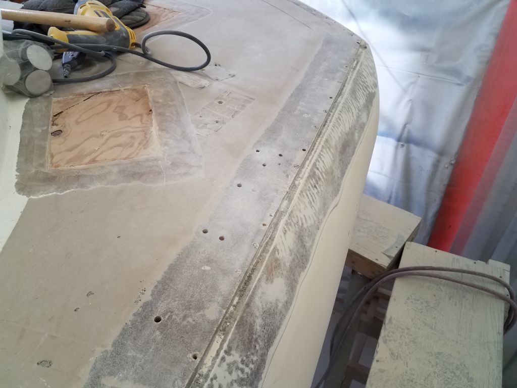
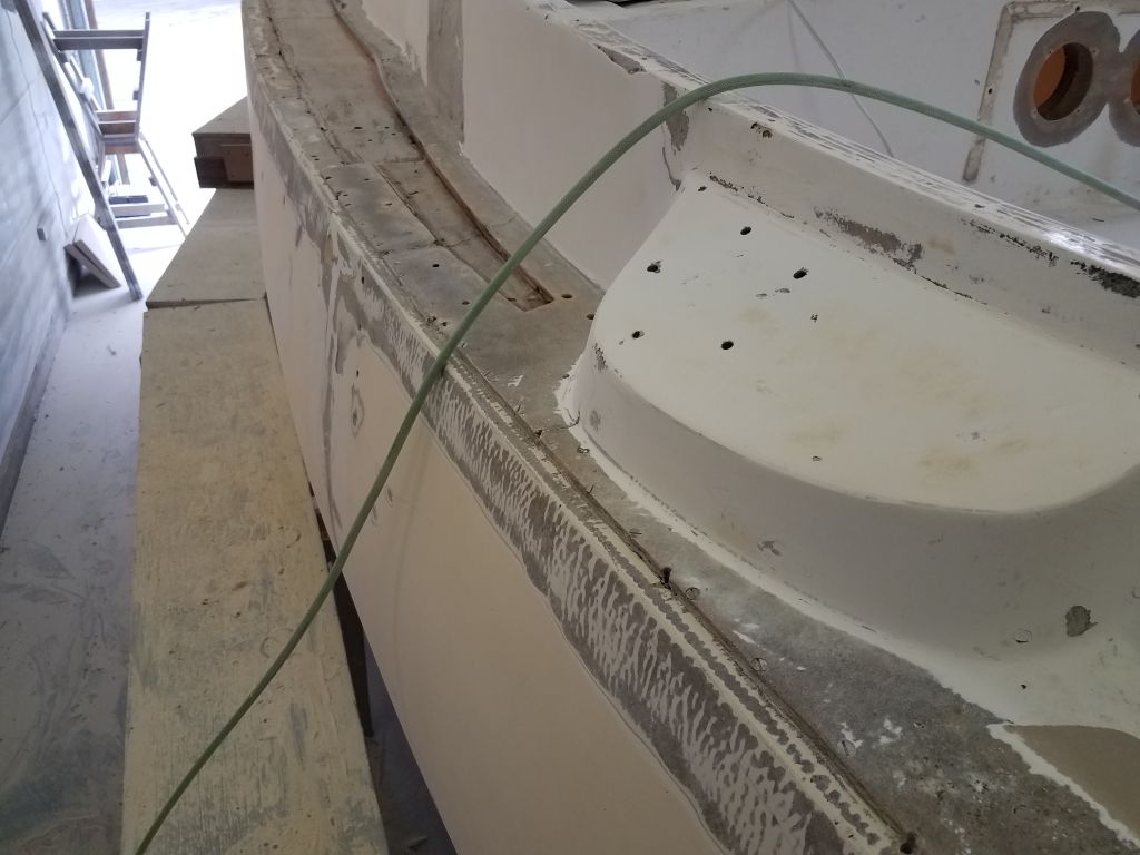
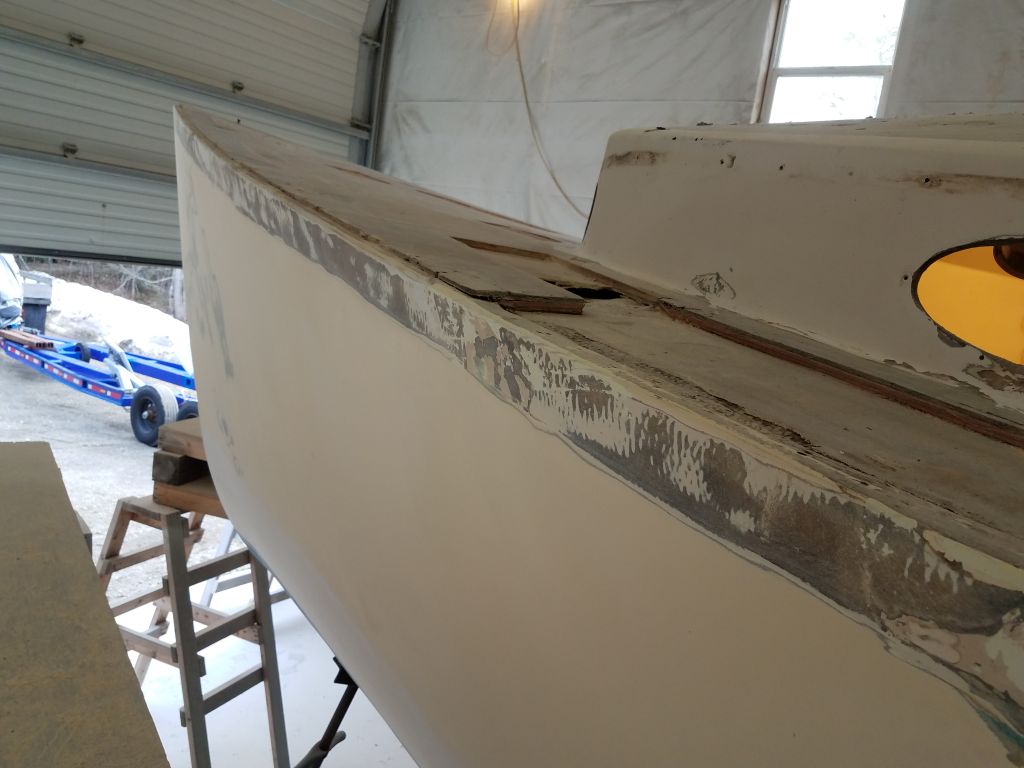
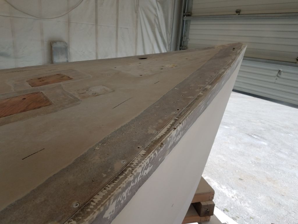
On the port sidedeck, I ground off the gelcoat and otherwise prepared the remaining adjacent deck areas surrounding the large area where I’d removed the old core and previous repair work, and also ground out several large cracks in the cabin trunk and forward part of the cockpit coaming that had been patched with a thick, ungroomed gelcoat putty. In the same session, I prepared the remaining small repairs on the foredeck, grinding away the gelcoat and tapering the edges of some existing holes and other areas where I’d removed the top deck skins for repair.
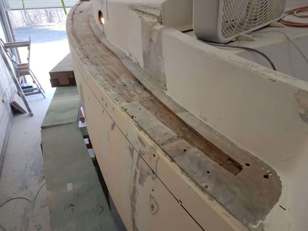

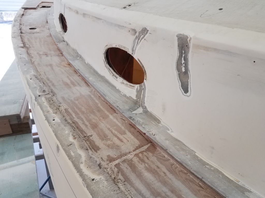


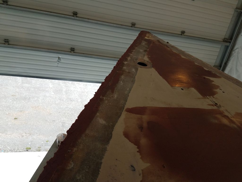
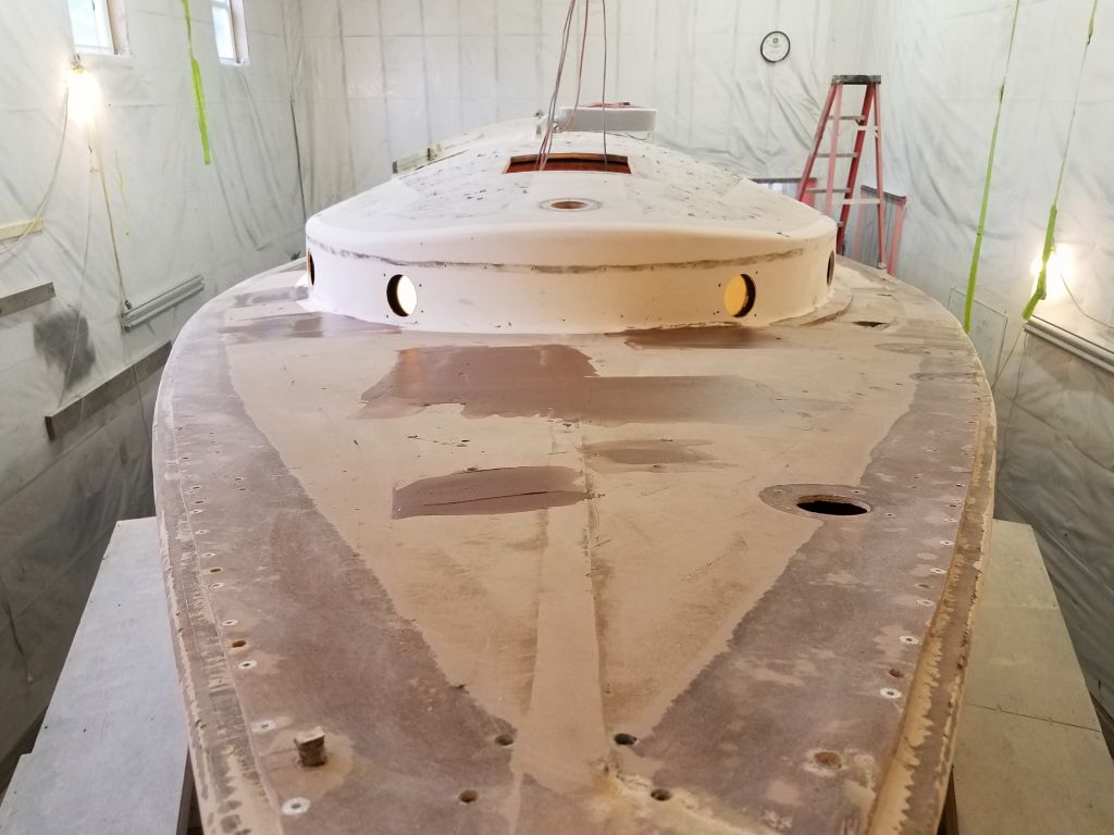
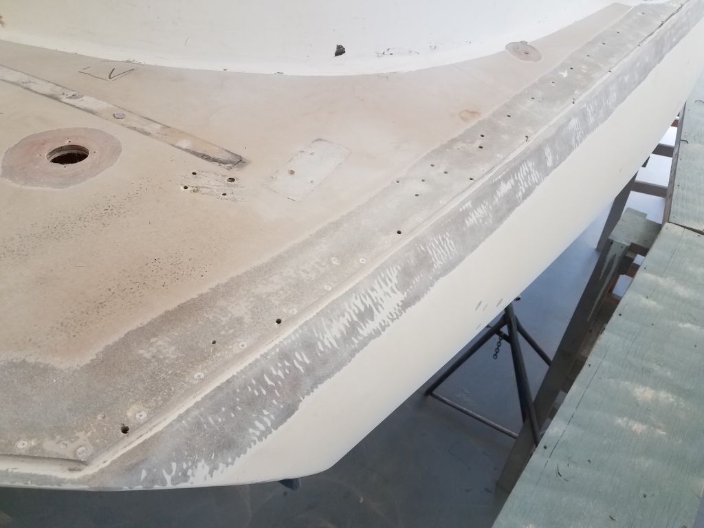
During the remainder of the day, I worked my way around the boat to prepare the top of the hull and the edge of the deck for fiberglassing later, starting at the port quarter and sanding away the gelcoat to the marks I’d made earlier and cleaning up the deck edge as needed. As I worked past, I also used the sander to clean up the inner deck skin on the port sidedeck and other related surface prep in this apocalyptic area that called out for my attention now. By the end of the afternoon, I’d worked around the stem and back down the starboard side to the cockpit area, leaving the last bit of the starboard side and the transom area for next time.


Total time billed on this job today: 7 hours
0600 Weather Observation: 24°, clear. Forecast for the day: sunny, 40s