110 Cookson Lane | Whitefield, ME 04353 | 207-232-7600 | tim@lackeysailing.com
Snow Lily | Saturday, March 16, 2013
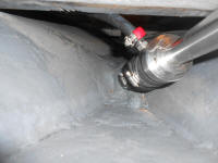
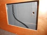
I got started with a couple small jobs, beginning with the air vent hose for the PYI dripless shaft coupling. The manufacturers of this fitting chose a 3/8" fitting for this hose, an oddball size that was unavailable in any "real" hose designed for underwater attachment, such as intake or exhaust hose. This left 3/8" fuel hose as the only realistic option for this vent. As directed, I installed the hose to the fitting and ran it well above the waterline into the galley locker overhead. The point of this hose, according to the documentation, was to ease the bellows "burping" process, a key factor in the shaft log's watertight integrity.
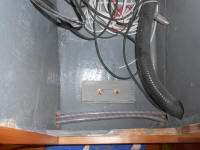
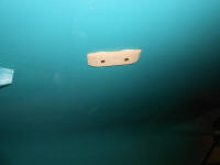
Portions of the electrical system required an external ground point--something normally accomplished through a cast iron engine block, which was not available in this instance--so, in accordance with the documentation supplied with the electric propulsion motor, I installed a grounding plate in the hull, to which I'd later attach whatever was needed. I chose a section of the hull accessible from within the electrical locker for the grounding plate. Installation was straightforward: once located, I drilled two holes for the mounting bolts, and secured the bronze plate from outside with the supplied bolts (one of which was gold plated for superior grounding performance) and sealant, with a backing plate within.
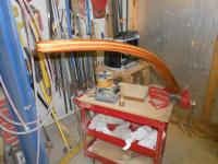
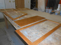
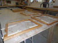
Next, I sanded, cleaned, and revarnished the cabin sole.
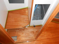
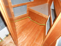
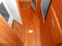
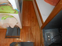
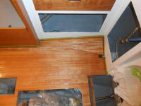
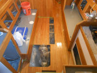
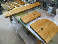
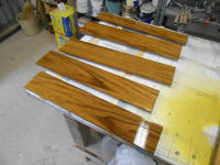
I also varnished the teak swashboards and tiller, and applied a coat of satin varnish to the remaining cabinet doors.
Getting ready to install the recessed throttle enclosure and the throttle itself, I decided to prepare the enclosure by creating the holes required for the throttle, the key switch, and an accessory outlet the owner requested for the cockpit. Pulling out the throttle unit, which was interconnected with several other electronic components related to the propulsion system, I determined that I'd need to temporarily disconnect the wiring to the throttle to install it, since there would be no way to snake the entire wire bundle with all its appurtenances through the boat to the electrical locker. There were eight or nine small wires attached to the throttle's electronic base, so I carefully documented their position in several hopefully failsafe ways, including installing wire labels, numerous photos, and a diagram.
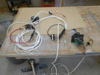
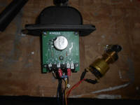
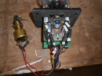
The wiring was a rat's nest, so to keep things more organized I separated various sections of the all-interconnected cables and temporarily wire-tied sections together in a logical way. Then, I disconnected the wires from the throttle so I could continue pre-installation.
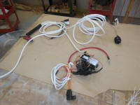
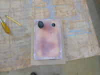
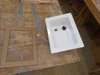
I made a simple cutout template of the base of the throttle, creating an opening large enough for the works of the throttle to pass through, then used the template to mark the opening on the bottom of the recessed enclosure, after which I cut out the square and drilled/tapped for machine screws, allowing me to temporarily install the throttle to check its fit and operation, and to better locate the additional components within the enclosure.
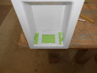
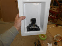
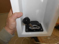
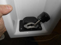
I drilled holes for the included key switch, and 12-volt accessory receptacle, temporarily installing both.
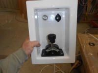
Next, I made a quick template of the enclosure itself, which would help me with locating the enclosure and cutting the opening required. I planned to install this on the starboard side of the cockpit, were it'd be accessible from within the locker but out of the way yet still easily accessible for the required wiring; this seemed referable to having this unattractive protrusion in the quarterberth, if I'd chosen to mount it on the port side, and the wiring would actually be more straightforward from the starboard side. It was late in the day, and I'd wait to install it till I could get back inside the boat, however.
Total Time on This Job Today: 6 hours
