|
Kaholee Refit |
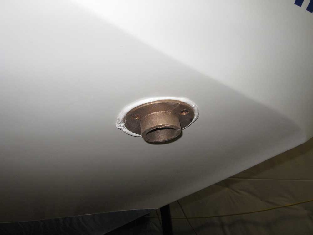
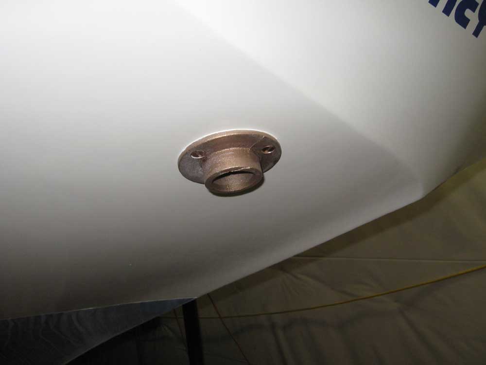
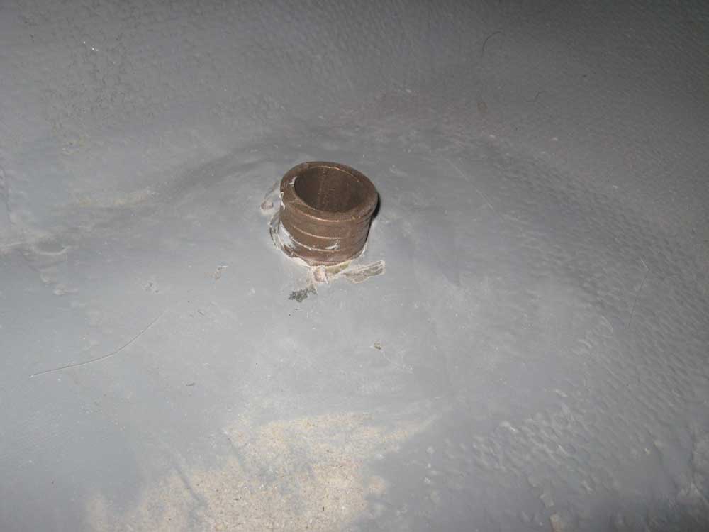
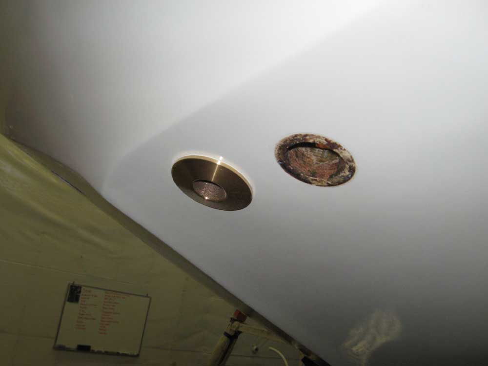
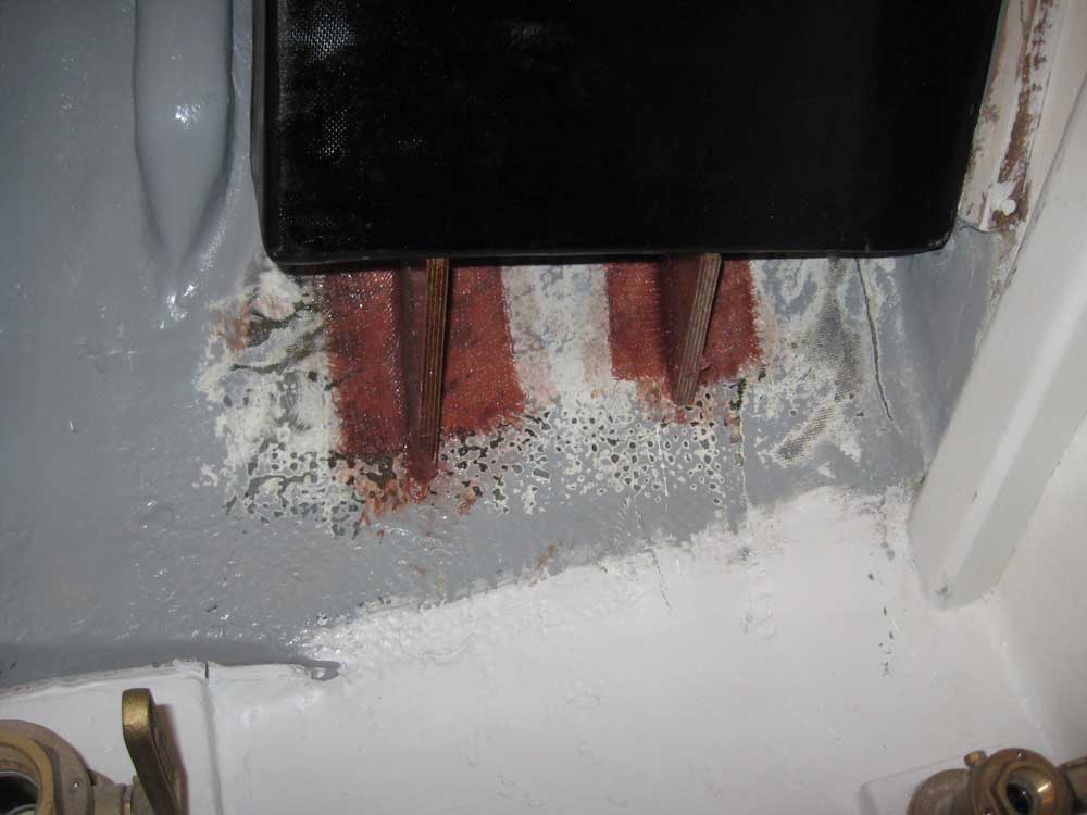
October 31, 2007 I got started with the exhaust outlet. With the new flanged fitting on hand, I used a hole saw to drill a new hole for the larger casting, centering the bit in the now-filled opening left behind by the old outlet. Then, I installed the new fitting with three bronze machine screws and plenty of sealant. While I was at it, I removed an old plastic bilge pump outlet on the other side of the counter; I had planned to reuse it, but found that the barb was not large enough for the 1-1/2" hose needed for the large emergency bilge pump, so I ordered a bronze replacement and filled the old hole so that I could redrill later for the new fitting. |
|
|
|
|
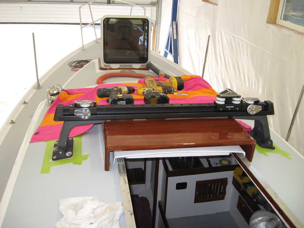
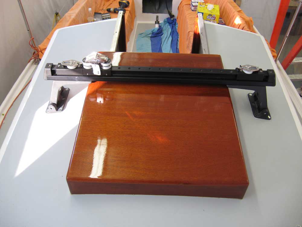
I moved on to the traveler installation. With the proper length and spacing of the traveler bridge track established during yesterday's work, I cut off the excess length on each side*. I determined the position of the cut using the supplied end caps as a guide, and marked the location with a strip of tape. Then I made the cuts carefully with a reciprocating saw. Next, I installed the center car and the two end cars, after first installing one bolt on each end to secure the track to the risers, since that bolt would be covered over by the end cars when they were installed. The end cars required two bolts to secure them, which passed directly through the cars, track, and riser. Schaefer provided bolts with the track, but only two of them were long enough to pass through the extra thickness of the cars; why, I pondered, did they only send two of these longer bolts when four were needed? Fortunately, I had some longer bolts on hand and was able to custom-cut them to the appropriate length. Then, I installed the final bolts required (four total on each end, including the end cars), and bolted the rubber end caps in place. With the traveler assembled, I set it on deck and bored 5 of the six holes in each base plate; one of the holes on each side was beneath the track, and I couldn't get the drill in there, so I simply marked these holes and drilled them afterwards. I tapped each hole for the 5/16-18 fasteners, except for that single center hole, which I knew would be difficult to get the bolt through to begin with, so I drilled that hole full size to allow the bolt to slip (rather than be threaded) through. *Why not make only one cut? Well, the end holes (8 or 10 of them) on the traveler track were pre-bored all the way through, while the ones towards the center from each end featured only pre-bored countersinks, without going all the way through. I wanted the closed holes to remain symmetrical when the track was installed, and cutting only one end might have made it asymmetrical. So I cut both ends evenly. |
|
|
|
|
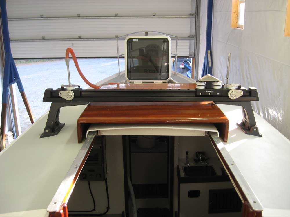
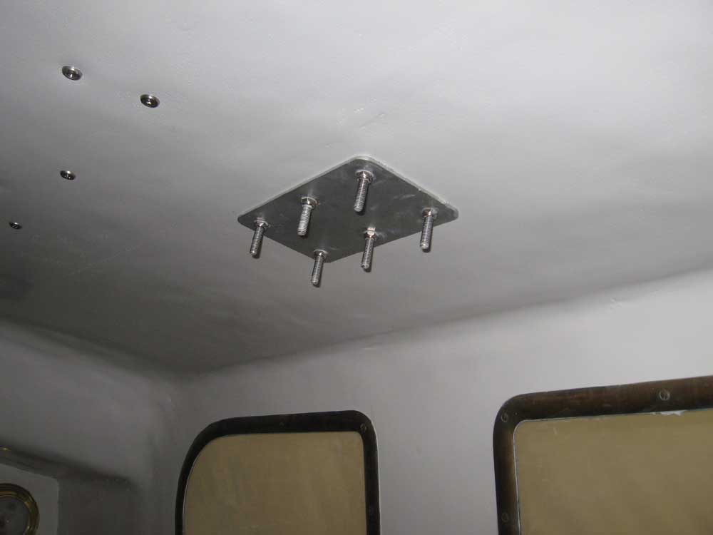
With the holes prepared, I installed the traveler in a bed of polysulfide. Though I should have known of the difficulty, I ran into trouble with those pesky center bolts--the ones beneath the track itself. The angle formed between the risers and the bases meant that the bolt was extremely challenging to get into place with the traveler assembled; perhaps I should have installed the bases first, then the track afterwards, but that had seemed as if it could easily lead to its own alignment errors. In the event, installation turned into a somewhat longer and messier chore than I had intended, since I had to pull the already-secured bases up in order to get those two bolts through, but eventually I got it. I cleaned up the excess sealant and tape. The traveler came with aluminum backing plates for belowdecks. I still need to cut off the excess bolt length. Other work remaining for the traveler is to install the two turning blocks on the deck that lead the control lines aft; I'll mock up the lines and position those shortly. |
|
|
|
|
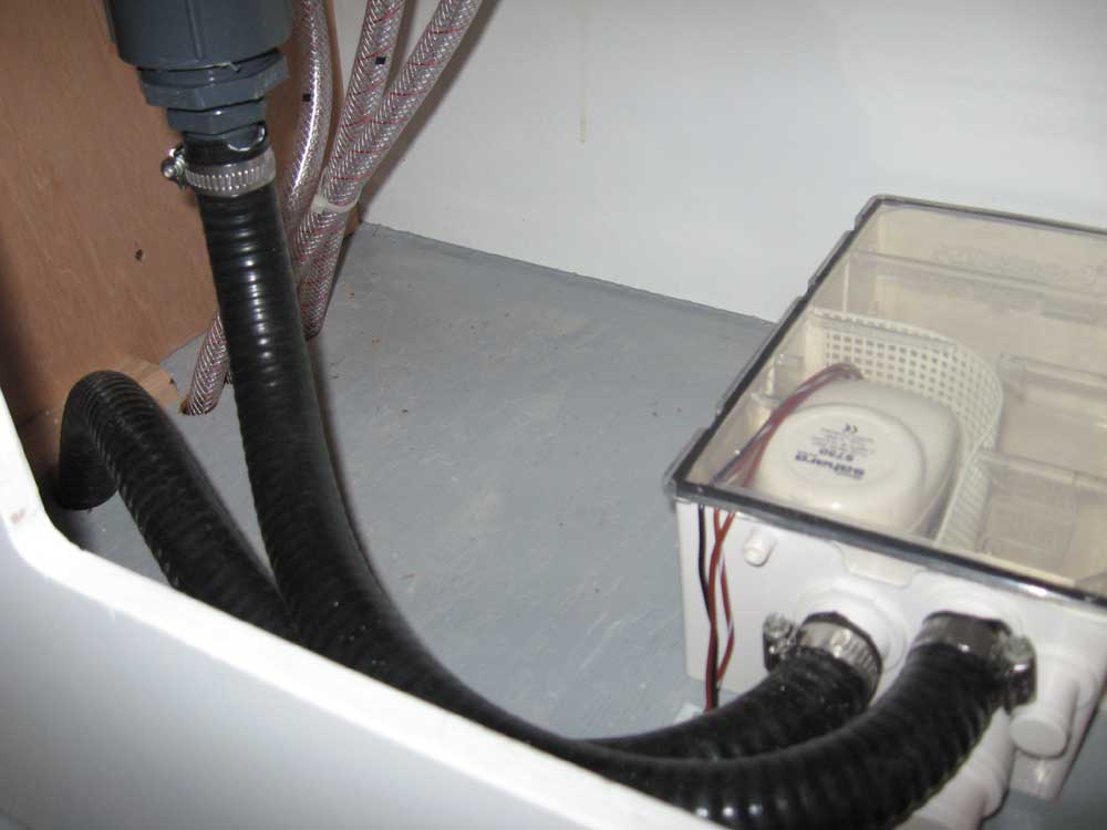
The holding tank was next. I'd been postponing its installation forever, but now was the time. I held the tank in position and measured for the length of discharge hose required, cut the hose, and secured it to the tank end; I also secured a long length of the hose to the tank inlet, since it'd be far easier to do this with the tank in the open. Then, I installed the discharge hose on the barb of the deck pumpout fitting, and "hung" the tank from the hose while I worked on a base support and securing system. To support the weight of the tank, I templated and then cut two plywood gussets for the space beneath the tank, and then epoxied and fiberglassed them to the hull. To further secure the tank, I planned to install either a simple strap to hold it in place, or possibly some wooden cleats that would bear against the cosmetic front panel that I'd eventually fabricate to cover the whole works. More on that later. I also installed the vent line from the tank to the nearby hull fitting. |
|
|
|
|
I knocked a number of smaller projects off the list as well, including cleaning up the excess sealant from the sink installation and securing the drain hose to the sump, thus completing the plumbing system 100%. |
|
|
|
|
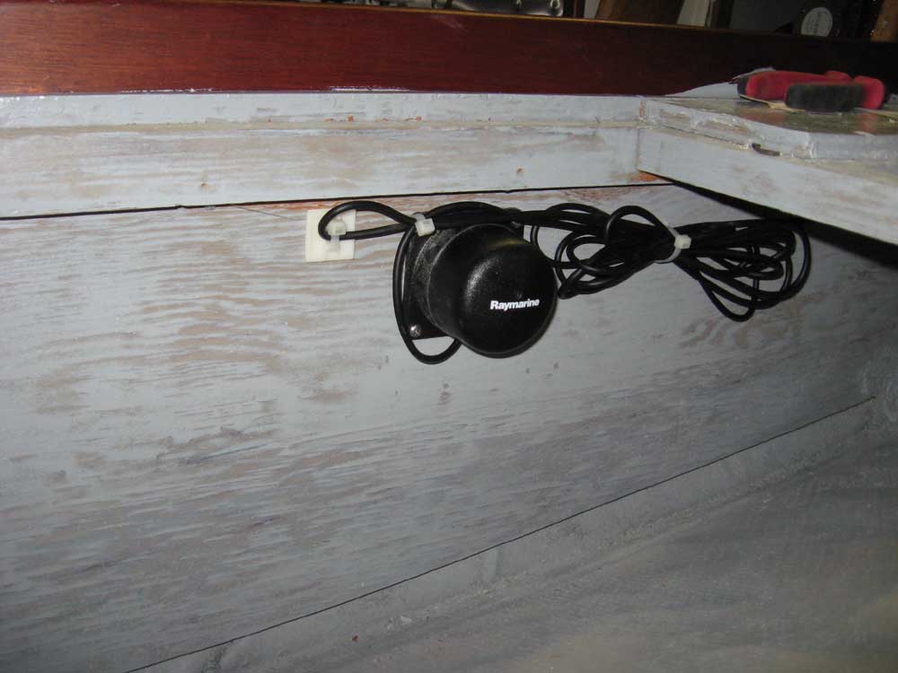
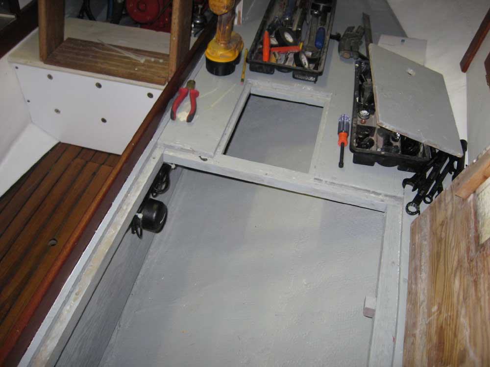
I installed the fluxgate compass required by the autopilot. I chose the best practicable location on the inside of one of the settee fronts, as close to the pitch and yaw center of the boat as possible (as described by the product directions). Earlier, you may recall, I had roughly determined its position and run the cable as required. |
|
|
|
|
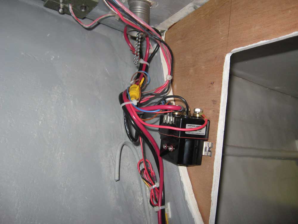
I made up the last terminal ends for the windlass wiring, and secured the cables to the control box as required; then, I tied up the excess wiring and successfully tested the windlass operation. |
|
|
|
|
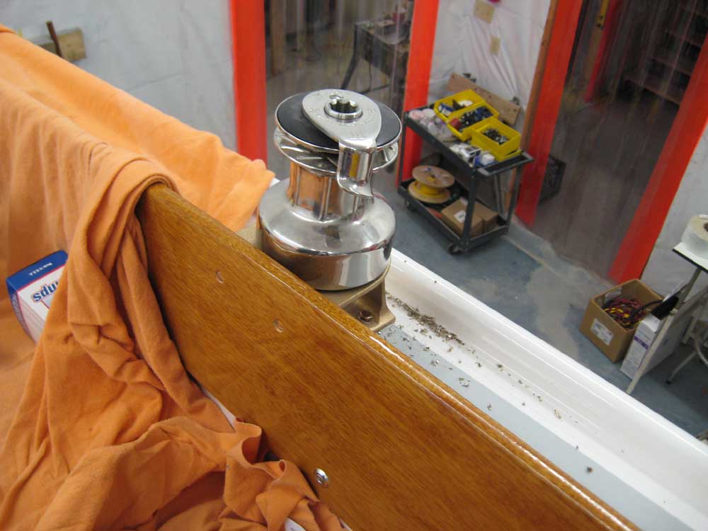
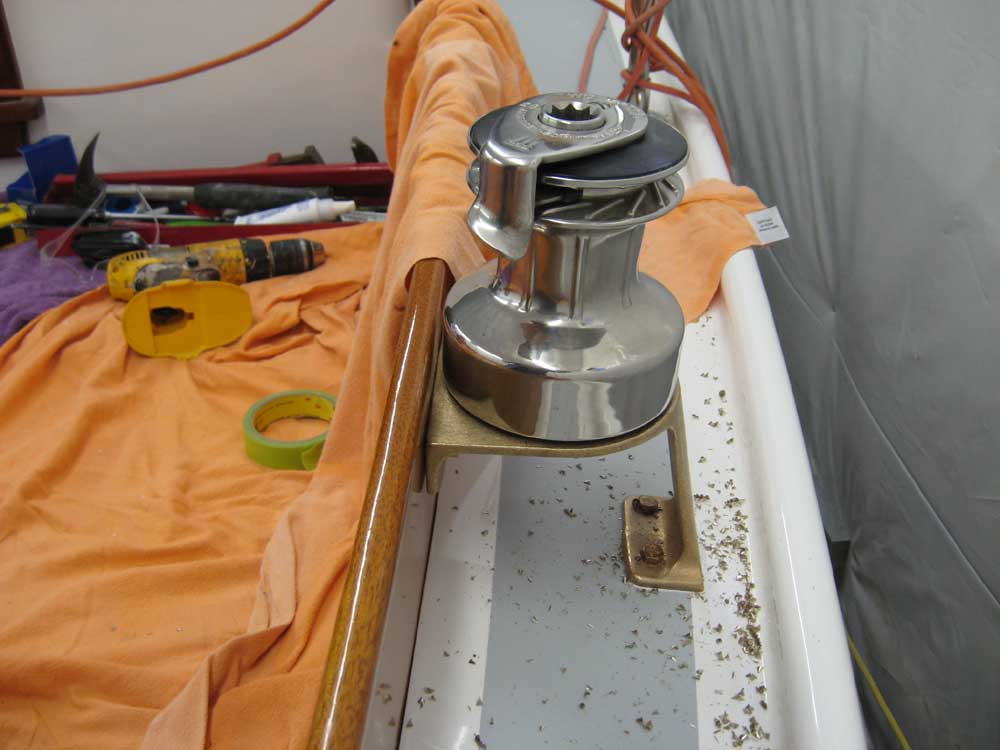
I installed the two Andersen 28ST winches on the new winch bases, using five bronze fasteners each as required. I really liked the simple disassembly of these winches: no irritating split rings, just one screw on the top, removal of which enabled the self-tailing mechanism and then the winch drum to be removed. Thus endeth another day. |
|
|
|
|
|
|
|
|
|