| Kaholee Refit |
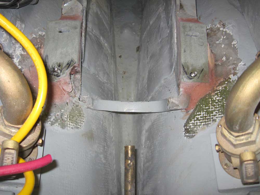
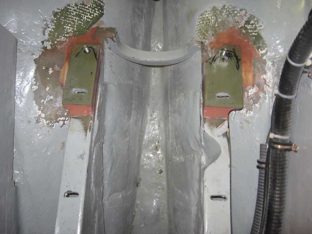
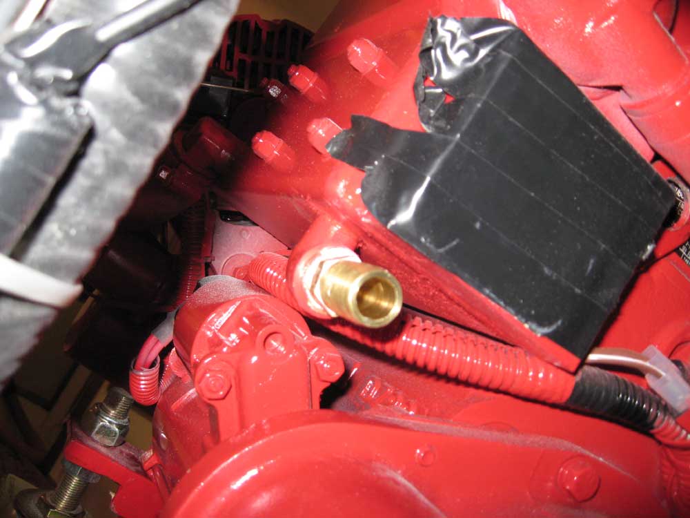
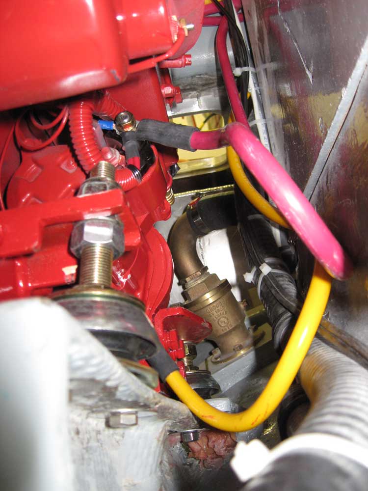
October 24, 2007 After cleaning up the newly installed fiberglass pads for the after engine mounts, I got right to work with the final engine installation. First, however, I removed one of the flex mounts from the engine and used it to mark the locations of the forward bolt holts on the aft mounts, for which I then cut slotted holes in the mounts. I had previously done this with the forward set of mounts, but had to wait till the new pads (with their permanent studs at the aft end) were in place in order to obtain an accurate placement for the forward holes on these aft mounts. While the engine was still out, I painted the inside areas of the new pads with Bilgekote to match the surrounding areas, though I left the top surfaces unpainted for now. (As nice as it would have been to paint everything now and let it cure, I needed to get the engine in place now, so I held off on the remainder of the painting till later in the day, after the engine was in place.) Before moving the engine one last time, I installed the after nipple (located beneath the exhaust flange) for the heat exchanger system for the potable water heater, since access was far easier with the engine out in the open. Because of the placement of the second nipple for this system (called the calorifier in UK nomenclature, apparently), I elected to hold off installing it until the engine was in place, lest the new nipple interfere with the operation of the chain hoist. |
|
|
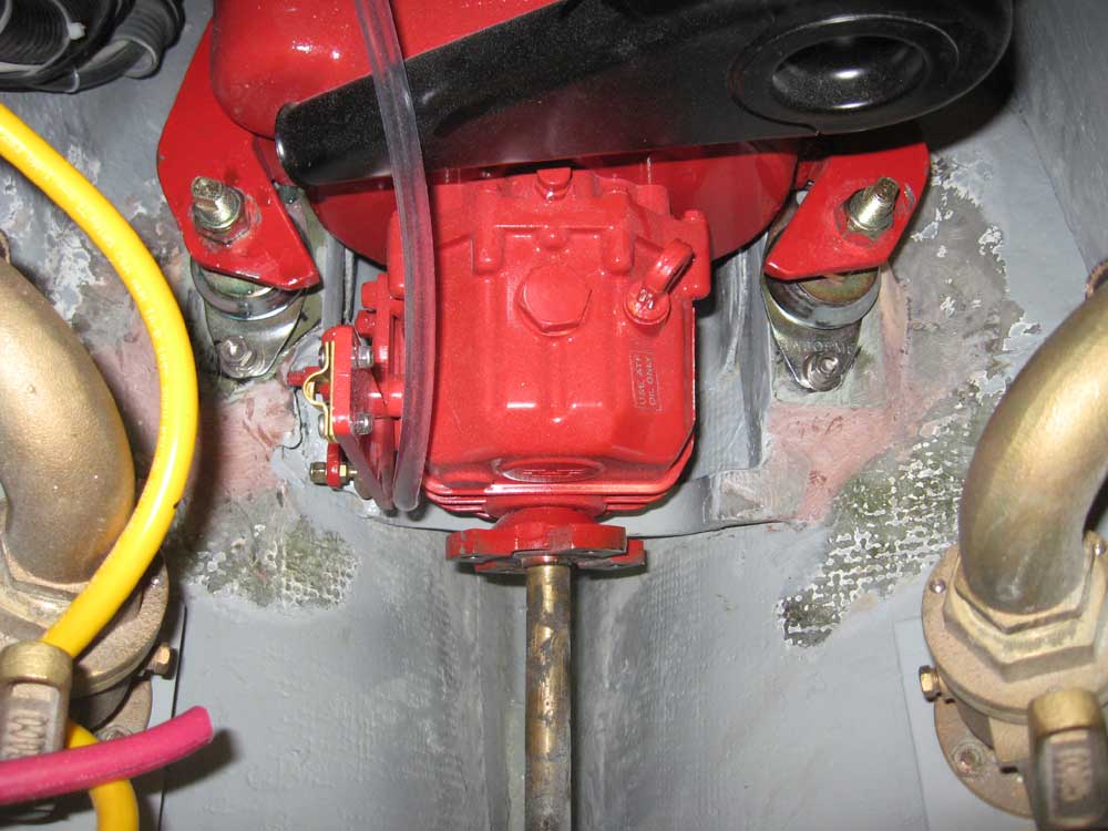
With that done, I craned the engine into place on the foundations and over the permanent studs at the aftermost end. With minimal fussing, I installed all 6 remaining bolts to secure the flexible mounts and tightened the nuts loosely after roughly aligning the engine with the mockup shaft. Final alignment will come quite a bit later, after I obtain a new shaft. |
|
|
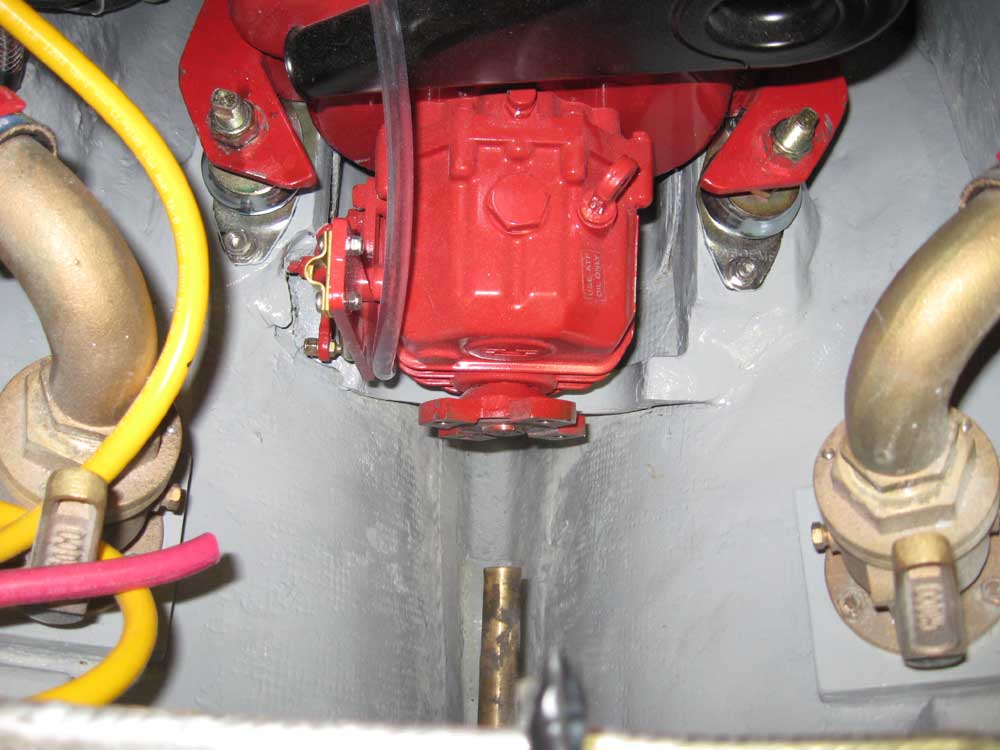
With the engine in place, I moved the crane out of the way and cleaned up a bit. Then, I installed the second calorifier nipple, this one located on top of the engine at the forward side. I selected a 90° elbow for this inlet, with a straight nipple for the outlet beneath the exhaust. |
|
|
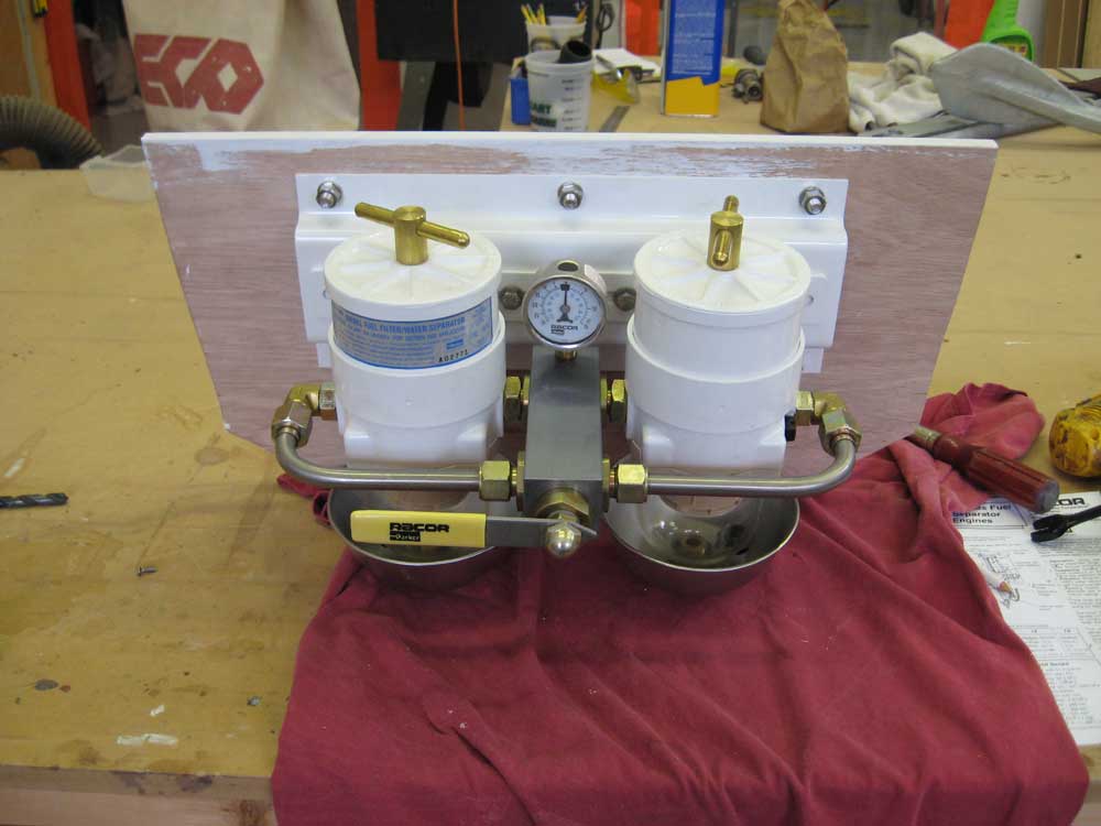
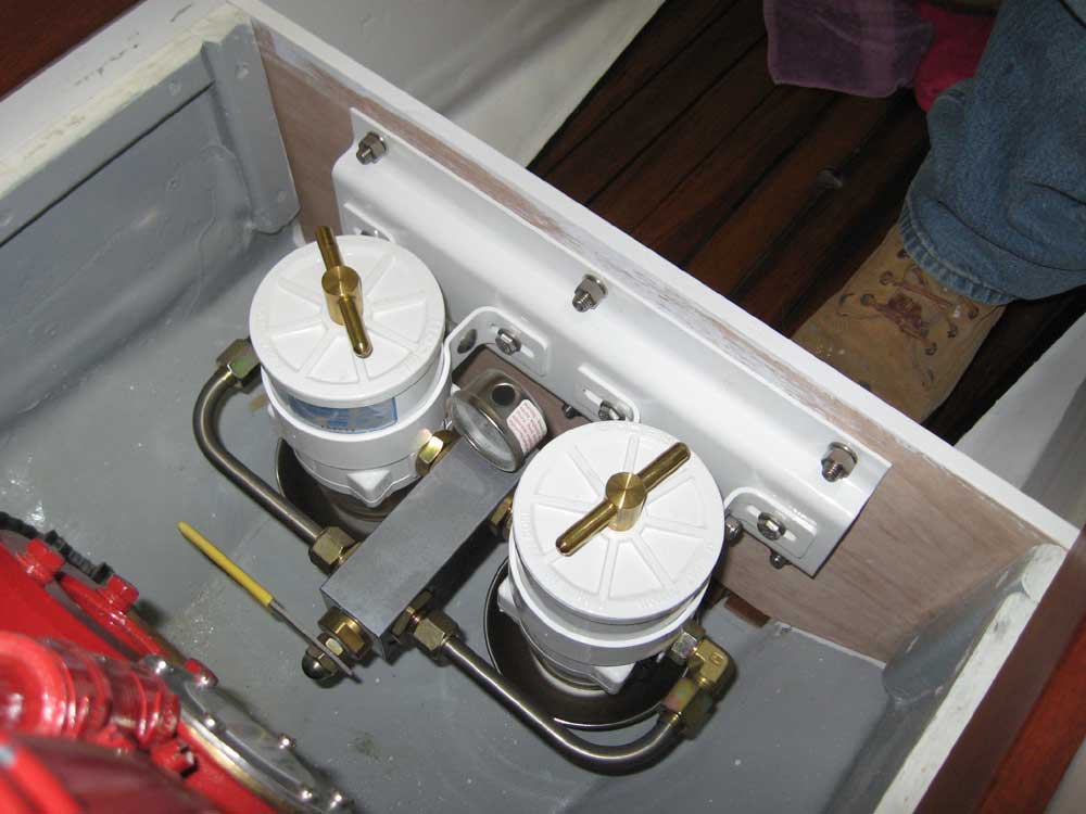
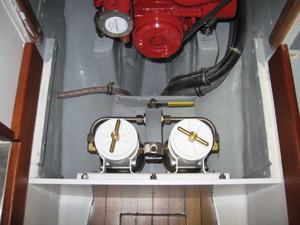
With the engine in place, I spent quite a bit of time determining what I needed to complete certain aspects of the installation, such as fuel lines, fuel fittings, and components of the cooling and exhaust system. Then, I placed an order for the requisite items so that they would arrive tomorrow and keep me knee-deep in parts (and therefore busy). Shockingly, this took half the afternoon. Also during this time, I mounted the Racor dual fuel filter system on the inside of the new companionway step front, where I had previously determined it would fit. I observed that the inlet and outlet ports required 3/4-16 fittings that were specific to the Racor filters, and added the appropriate fittings to my order so that I could connect fuel line barbs as required. (Since this filter system is designed and intended for much larger vessels, there was not a direct fitting to adapt to 1/4" fuel hose, so an adapter fitting between the filter threads and the normal-sized threads of typical 1/4" fuel barbs was required.) The placement of the Racors in this location didn't allow much room beneath for operation of the drain cocks on the metal filter bowls, so I marked the bottom of the compartment adjacent to the drains and contemplated drilling relatively large holes to allow any drainage to flow into a waiting receptacle to be placed in the bilge beneath; as of this writing, I had not yet confirmed that this would be my route of action, however, and had not yet drilled the holes. |
|
|
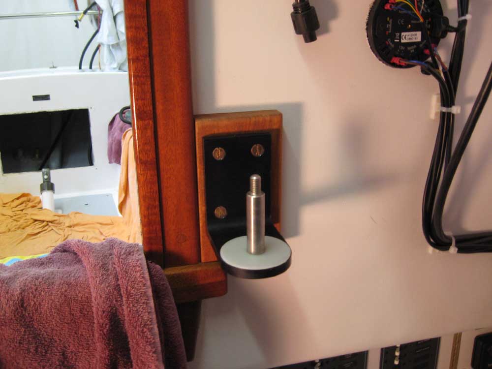
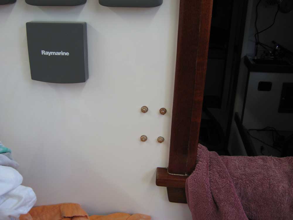
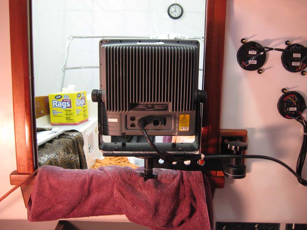
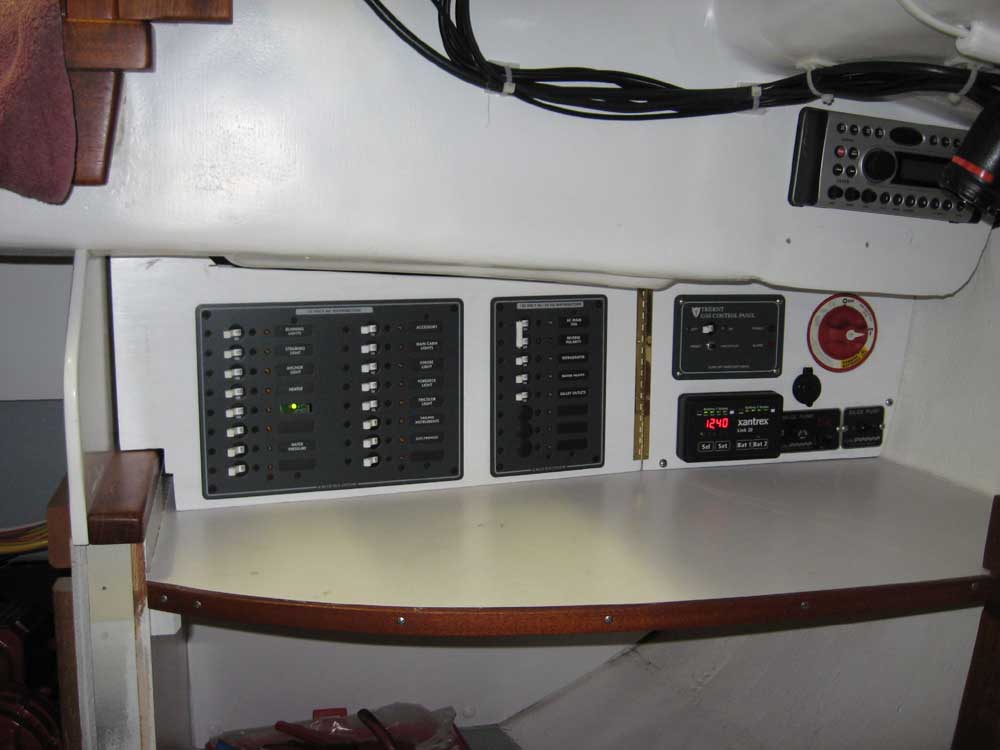
At some point, for reasons known only to the inner workings of my mind, I became dimly aware that I might have forgotten something about the Raymarine transducer installation. Not wanting to face the truth, but having no choice, I inspected the transducer plugs (both the blank and the impeller) that pass through the top of the bronze through hull, and confirmed--as I had suspected--that I had failed to route the transducer cable first through the plastic nut required to hold the plugs in place within the housing. Since I had previously run and tied up the transducer cable all the way aft through the engine room, electrical panel, and on to the instruments themselves, I found this discovery to be a bit inconvenient. There was nothing I could do but untie the transducer cable (and therefore the entire wire bundle), cut all the ties securing it in place along its length (31), pull the cable back forward and run it through the plastic nut. Naturally, I was overjoyed by this process, but in the scheme of things it actually didn't take that long. While in wiring and electronics mode, I decided to install the swing-arm bracket for the large Raymarine chartplotter/radar display. Yesterday, I prepared a mounting block for this, and now, with sufficient varnish in place on the block, I secured the swing arm to the aft bulkhead in the cabin above the electrical panel. Because of the heavy weight of this item, we had previously determined a requirement to through bolt the bracket base. I drilled and tapped for four 1/4-20 bronze fasteners, which I then used to secure the bracket and backing block, all bedded in a quantity of 4200, chosen for its close availability from yesterday's projects as well as its additional adhesive strength to reinforce the overall installation. The protruding bolt ends and nuts into the cockpit were simply something that had to be; later I planned to cut off the small excess length of the bolts for a cleaner appearance. |
|
|
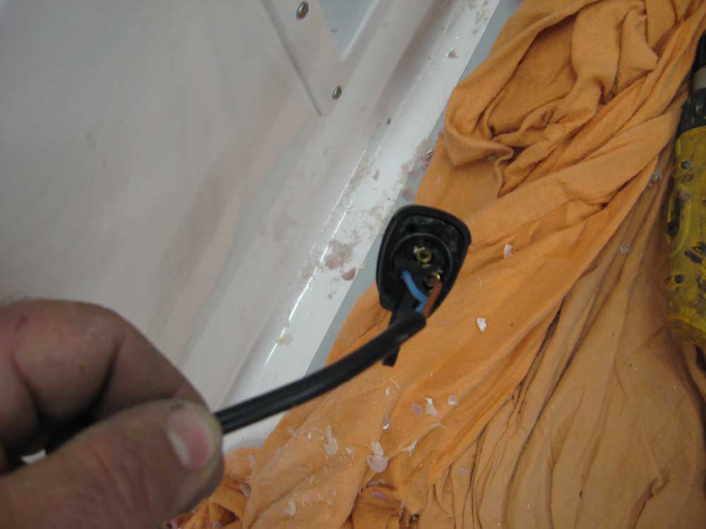
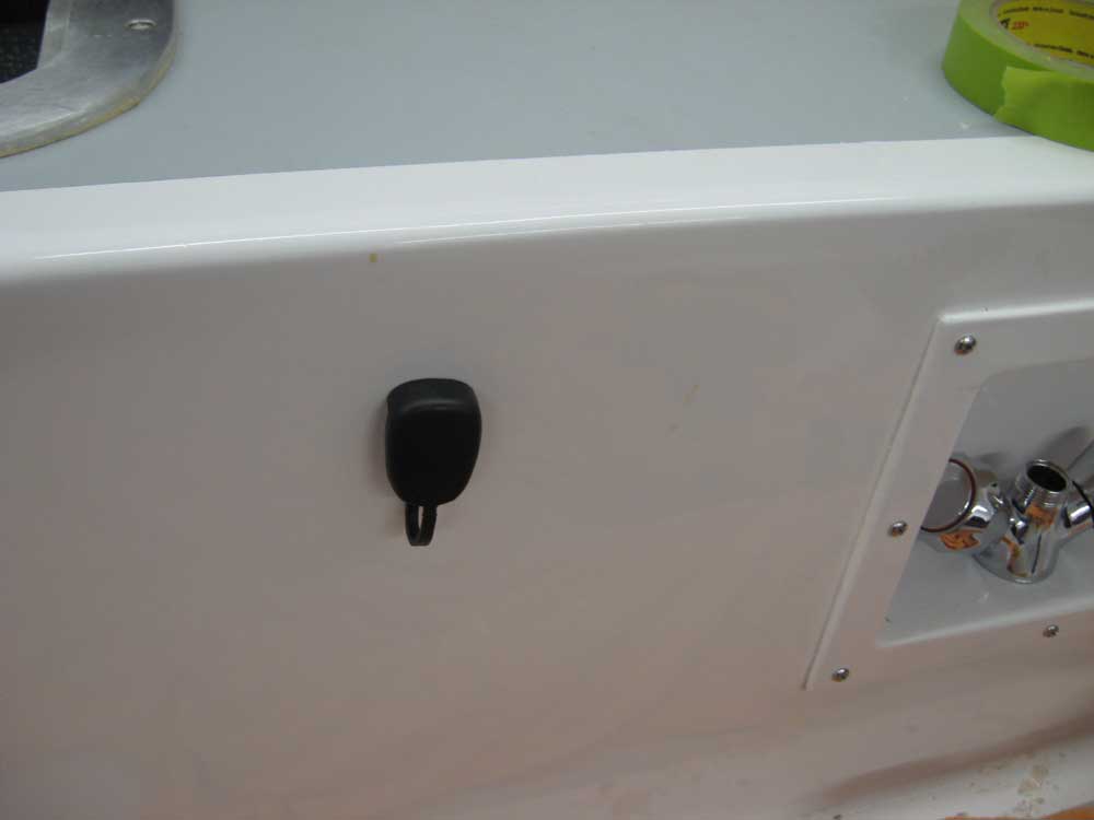
There were a few wiring connections remaining to be made: the wires to the tillerpilot arm drive, and the main red and yellow cables (starter solenoid and main system ground) to the newly-installed engine. I was pleased to find that the two-conductor sheathed cable provided with the autopilot was long enough to reach to the starboard side of the cockpit without additional length, and I drilled a 3/4" hole in the cockpit well for the supplied plug, ran the wires through, and secured them to the appropriate studs in back. For now, I left the plug loose and didn't secure it to the cockpit. I cut the previously-run lengths of battery cable to an appropriate length and installed lugs, then secured the ends to the starter solenoid (red) and one of the studs securing the starter to the engine block (yellow), which completed the basic wiring for the electrical system. With that, I checked over the wiring connections I'd made for the batteries, Xantrex monitor, shunt, and related items, and, following the start-up procedure dictated by the Xantrex manual, connected the various wires and cables to the battery terminals as required, thereby energizing the electrical system for the first time. I tested most of the installed equipment to ensure that it worked, and called it quits for the day. |
|
|
|
|
|