

|
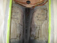
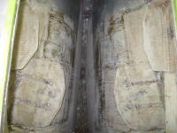
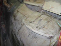
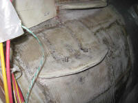
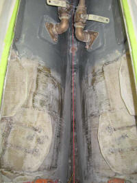
Equinox Project | Monday, March 9, 2009 With Friday's fiberglass efforts well cured, I began today by water-washing the new material and then sanding as needed to remove the rough, protruding edges and clean up the new foundations. I removed the plastic tubing around the forward mount bolts and cleaned up a slight ridge there with a chisel and some hand sanding. Later, I'd fill the circular voids flush with the surrounding surface. |
  |
|
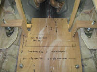
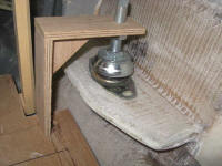
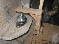
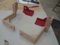
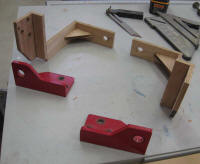
After cleaning up from sanding, I went to work building mockups for the new aft engine mounts that I'd have to have fabricated at a machine shop. Since the shape of the hull was such as to prohibit the installation of flexible mounts beneath the existing rear engine mounting flanges, which were bolted to the engine, I had earlier (as described at that time) raised the new rear foundations to accommodate this. Now I just had to figure out the shape of the new pieces to transfer the engine's weight from the block to the new foundations some inches higher. To keep things as simple as possible, I elected to not make any major changes to the geometry or position of the existing aft mounting flanges, which will be come more clear later on. I restrung the shaft centering string, using some reference marks I'd made before removing it earlier, and reinstalled the engine template. After aligning it properly, I milled some 9mm (3/8") plywood into 2" wide strips, and then cut and fit these strips as needed to construct a pair of mount mockups, leading from the flex mounts down to the top of the engine template. Because the bottom surface of the engine template equated to the bottom surface of the existing engine mounting flanges, and because the thickness of the plywood engine template matched that of the steel mounting flanges, the top surface of the engine template also equated to the top of the mounting flanges. My first set ended up slightly the wrong dimensions, but I could quickly build a new set with the corrected information. I hot-glued all the pieces together as needed. |
 |
|
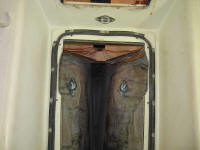
Before removing the engine template one last time, I removed the shaft string and reopened the stern tube. Then, I slid in the propeller shaft and noted where it contacted the engine template. It was just a small amount high of center, and amount that could and would be easily adjusted out with the flexible mounts in the final installation. The second photo shows a view through the stern tube from outside the boat. |
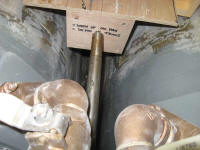
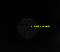 |
|
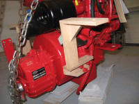
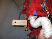
With these basic L-shaped brackets complete, I added gussets to the top corner (which I also anticipated being part of the final steel fabrications). I removed the new mockups, and then down on the engine I removed the aft pair of mounting flanges and, using the same plywood as before, made some near-identical mockups of plywood, changing only the aft end, where I removed (on the plywood) the section of the flange that contained the large hole for the flex mount stud, instead maintaining a consistent width aft which mated up with the L-shaped bracket I'd made earlier in the appropriate position. I milled bolt holes in the vertical segment to match the existing ones. I glued the new base section to the L bracket (there was a slight width inconsistency that I'd correct in a final version before sending this off for replication in steel). Next, I bolted the new wooden mounting flanges to the engine to check bolt hole alignment and overall clearance and placement issues. The starboard mount reduced clearance for the eventual throttle cable (where it led to the bracket clamp) to a minimum (it would still work as), and this caused me to consider other ways I might build the mount to improve this clearance. However, the overall concept was sound, and good enough for the moment. On the port side, I confirmed that the exhaust riser would clear the mount on that side. I removed the plywood mockups for now. |
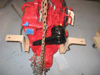
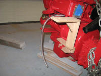
  |
|
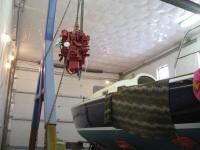
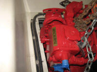
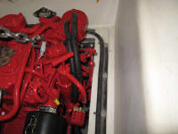
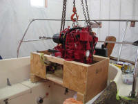
It was time to test the engine's fit in the boat, and to confirm that my new after mounts would work as intended. Working off the plywood engine template is one thing, but only having the actual iron in the boat would prove its fit. Plus, I anticipated some minor clearance issues with the engine's width versus the width of the opening in the cockpit sole, and I wanted to square that away. To prepare, I removed all excess tools and junk from the cockpit, and installed the forward pair of flex mounts in position with the nuts loose, to allow movement side-to-side. Then, I raised the engine into the boat and began to set it in place. As expected, I found that portions of the engine were too wide for the opening into the engine room, mainly a hose run on the port side and the oil dipstick and transfer pump on the starboard. After marking the deck in way of these protrusions, I moved the engine aside and cut away the area inside my marks, leaving the gasket area and all existing boltholes intact. |
  |
|
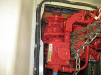
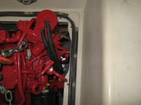
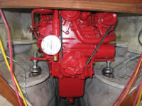
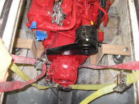
This time, the engine fit through with relative ease, and before long I had the forward end resting on its flex mounts. At the after end, with nothing to hold it in place during this test, I slung a strap beneath the aft end to support and adjust it. |
 |
|
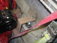
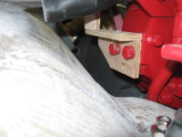
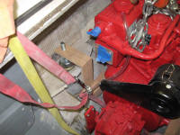
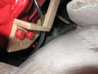
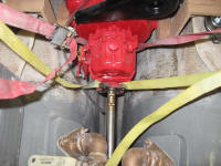
Once the engine was in, I temporarily installed the plywood mounts to see how everything fit. I was very pleased with how well the reality meshed with the concept; the new mounts would be perfect. Again, I spun the shaft in through the stern tube and pressed it against the transmission flange. The overall alignment at this early stage looked good, with the shaft ending up right in the center of the flange where it should have been; the engine placement and the pressure of the strap tended to pull the engine artificially to port just a bit, causing the misalignment shown in the photo. The final photo in this section shows a view through the stern tube from outside. In any event, I wouldn't drill boltholes for the aft flex mounts until the final installation, to ensure that they were in just the right place. I made some reference marks to mark their rough location, however, so that I could add some supports beneath the foundation platforms in the meantime and ensure that I didn't interfere with the future boltholes. |
 |
|
Pleased with everything, I removed the engine and set it back in its crate, which I placed on deck to avoid lowering the engine all the way to the ground again. I planned to make some fine adjustments to the plywood mockups and then drop them off at a machine shop for fabrication in the near future. Oh, I almost forgot that I also sanded and varnished the swashboards, and ordered the new propeller (11x9 three blade sailer; 8 week delivery time). |
 |
|