|
|
~MENU~ |
| Home |
| The Concept |
| The Boat |
| Bringing Her Home |
|
Weekly Progress Log |
|
Daysailor Projects |
| The Boat Barn |
| Resources |
| Other Sites |
| Email Tim |
|
|
|
Systems: Through Hulls and Seacocks |
|
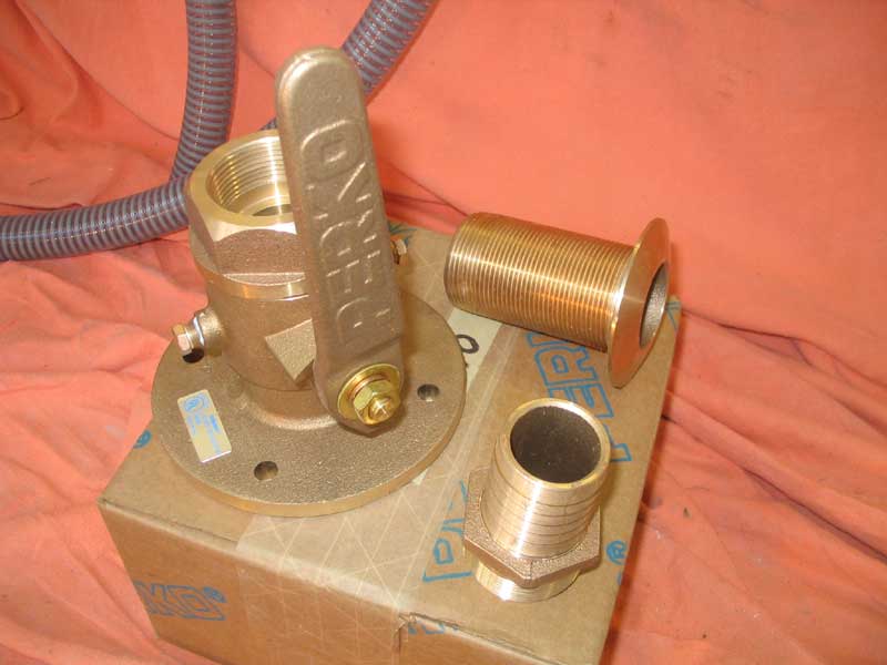
I only required three through hull fittings:
two for the cockpit scuppers and one for the engine raw water intake.
I planned to use bronze fittings, with flanged seacocks. To prepare for installation, I first chose the locations for the three fittings. In my roomy bilge, I wanted locations that were convenient for the hoses required for each application, but also wanted the fittings to be not directly in the path of regular maintenance to other areas--and yet to remain easily accessible for seacock maintenance and operation. |
 After
a brief mockup, I located the two large 1-1/2" seacocks for the cockpit
scuppers, one on each side of the fuel tank platform and slightly
outboard. The hull in this area was nicely flat, which would make
installation that much more straightforward. I located the 3/4"
engine raw water intake just outboard of the starboard engine
foundation, near the raw water pump on the engine. After
a brief mockup, I located the two large 1-1/2" seacocks for the cockpit
scuppers, one on each side of the fuel tank platform and slightly
outboard. The hull in this area was nicely flat, which would make
installation that much more straightforward. I located the 3/4"
engine raw water intake just outboard of the starboard engine
foundation, near the raw water pump on the engine. |
|
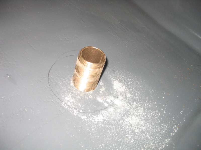
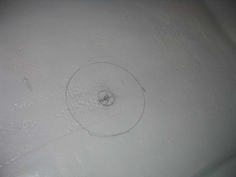
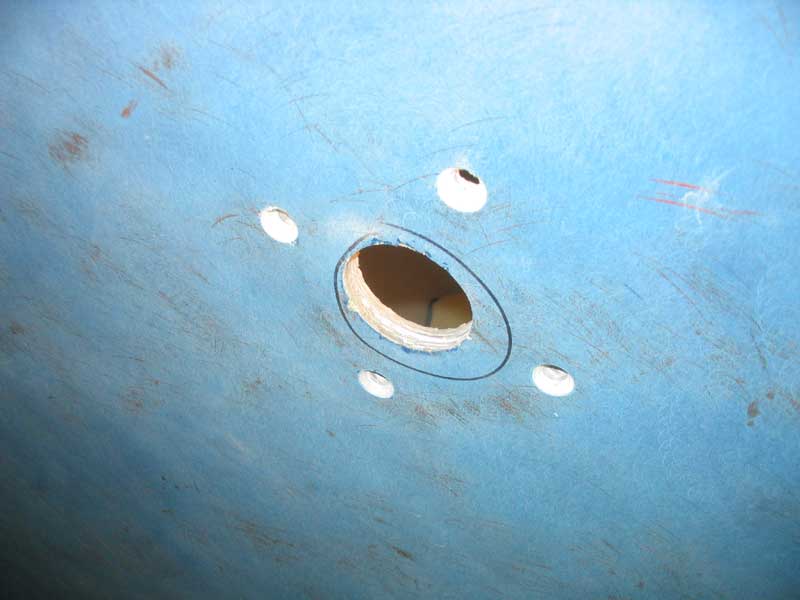
With the locations marked, I drilled small pilot holes through from inside to out, and then, outside the hull, bored the larger holes required for the through hulls with a hole saw.
|
|
|
|
I decided to build the backing plates from fiberglass. I hurriedly ordered two sheets of 1/2" pre-manufactured laminate from McMaster-Carr, for delivery the next day. When the sheets arrived, I cut them into approximately 6" squares (just the right size for the seacock bases). I needed a total thickness of 1-1/2", so after sanding the surfaces of each square, I epoxied three pieces together to make the requisite thickness. I made two of these setups, and allowed them to cure overnight. I also glued the remaining two pieces together, intending them for use with the smaller engine seacock, which would also require a backing plate. |
|
When the epoxy cured, I sanded off any squeezeout, and carefully trimmed the edges of each base plate flush on the table saw, to eliminate any unevenness. I found the laminate to be extremely hard, and difficult to cut and sand. It didn't help that my table saw blade was duller than dull, but it was made even worse by running the iron-hard laminate through. |
 With
all three backer plates complete, I next drilled large holes in the
center to accommodate the through hull fittings. I drilled the
holes somewhat oversized to allow for some leeway in installation.
Then, with the through hull mocked up in the hull, I placed the backer
plates and marked the seacock location on top, as well as the fastener
holes. I drilled the fastener holes for 5/16" diameter fasteners
at the drill press. With
all three backer plates complete, I next drilled large holes in the
center to accommodate the through hull fittings. I drilled the
holes somewhat oversized to allow for some leeway in installation.
Then, with the through hull mocked up in the hull, I placed the backer
plates and marked the seacock location on top, as well as the fastener
holes. I drilled the fastener holes for 5/16" diameter fasteners
at the drill press. |
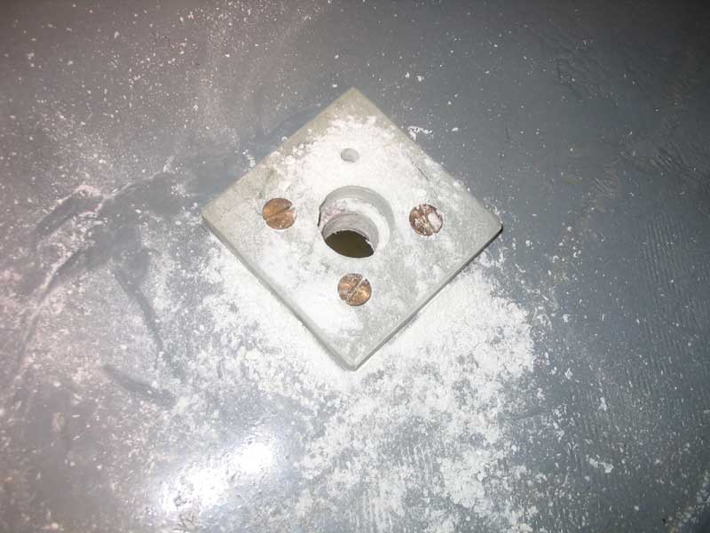
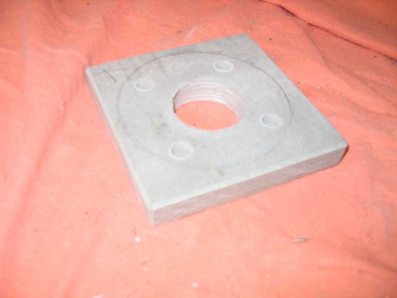 I
discovered at this time that I had made the backing plate too thick for
the small engine seacock; I had glued up two pieces of 1/2" laminate
without checking how much was actually required, and it turned out that
I only needed a single thickness. With a rather high level of
difficulty, I cut the glueup in half, essentially severing the glue
joint I had made only about 12 hours earlier. Given the hardness
of the laminate, this was quite a chore; the table saw was too dangerous
to use, as excessive force was required to push the material through, so
I clamped the pad in a vise and used a carbide blade in my reciprocating
saw. It worked, but was still difficult. I sanded the rough
cut relatively smooth, and then reduced the overall size of the plate
from 6" square to about 4", more in keeping with the size of the flange
on the smaller seacock. On each of the three pads, I sanded a
bevel at all the corners to eliminate any sharp edges. I
discovered at this time that I had made the backing plate too thick for
the small engine seacock; I had glued up two pieces of 1/2" laminate
without checking how much was actually required, and it turned out that
I only needed a single thickness. With a rather high level of
difficulty, I cut the glueup in half, essentially severing the glue
joint I had made only about 12 hours earlier. Given the hardness
of the laminate, this was quite a chore; the table saw was too dangerous
to use, as excessive force was required to push the material through, so
I clamped the pad in a vise and used a carbide blade in my reciprocating
saw. It worked, but was still difficult. I sanded the rough
cut relatively smooth, and then reduced the overall size of the plate
from 6" square to about 4", more in keeping with the size of the flange
on the smaller seacock. On each of the three pads, I sanded a
bevel at all the corners to eliminate any sharp edges. |
|
Sanding, sizing, drilling, and finalizing the backing plates turned out to be quite a labor of love and took much of the morning. I sure hoped someone would one day gaze upon my backing plates and realize how nice they were, but I doubted it.
|
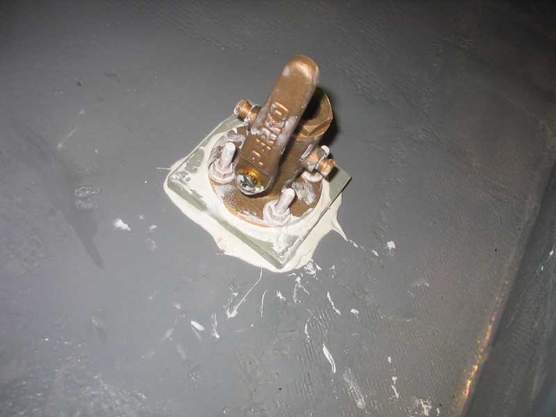
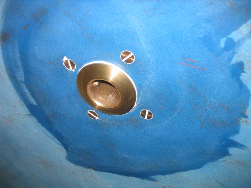
 I
covered the bottom of the through hull flange with 5200, and also coated
part of the threads, and prepared to install it. Unfortunately, I
discovered that I couldn't get the through hull threads to properly
engage, perhaps because there was a slight difference in angle now that
the seacock was tightly secured. Therefore, I had to loosen the
four bolts to allow the seacock to move slightly, after which we quickly
got the threads aligned and started. Once that happened, I could
re-tighten the bolts, and then finish securing the through hull from
below. My little stepped through hull installation tool, which
grabs the cast ears inside the through hull, was invaluable for this
chore. I
covered the bottom of the through hull flange with 5200, and also coated
part of the threads, and prepared to install it. Unfortunately, I
discovered that I couldn't get the through hull threads to properly
engage, perhaps because there was a slight difference in angle now that
the seacock was tightly secured. Therefore, I had to loosen the
four bolts to allow the seacock to move slightly, after which we quickly
got the threads aligned and started. Once that happened, I could
re-tighten the bolts, and then finish securing the through hull from
below. My little stepped through hull installation tool, which
grabs the cast ears inside the through hull, was invaluable for this
chore. |
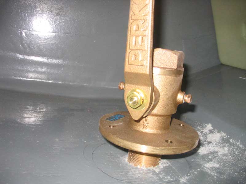
 With
one fitting installed, I moved on and repeated the process for the
remaining two, only slightly modifying my procedure to reflect the
difficulties learned during the first installation. Once each
fitting was installed, I cleaned up the large amount of squeezeout both
inside and out. I was very pleased with how the installations
turned out. The four bolts securing the engine seacock were overly
long and extended well into the boat, so I planned to cut the excess off
later on. With
one fitting installed, I moved on and repeated the process for the
remaining two, only slightly modifying my procedure to reflect the
difficulties learned during the first installation. Once each
fitting was installed, I cleaned up the large amount of squeezeout both
inside and out. I was very pleased with how the installations
turned out. The four bolts securing the engine seacock were overly
long and extended well into the boat, so I planned to cut the excess off
later on. |
|
|
|
Back to the Main Menu> |