|
|
~MENU~ |
| Home |
| The Concept |
| The Boat |
| Bringing Her Home |
|
Weekly Progress Log |
|
Daysailor Projects |
| The Boat Barn |
| Resources |
| Other Sites |
| Email Tim |
|
|
|
Systems: Rudder Construction |
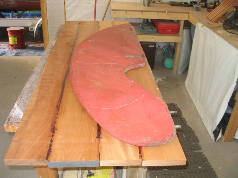
| Despite a brief dalliance with the thought of building a composite rudder, I eventually returned to the realities at hand and decided to build a new rudder of solid mahogany, build up from planks secured with waterproof adhesive and, as necessary, drift pins. |
|
I took an old rudder shaft to my local prop and machine shop, along with some measurements I had made of the new, longer rudder tube, and worked out the final details with them, including the shape and size of the keyway at the top of the shaft, which was to mate with a solid bronze tiller head and strap from Spartan Marine. After a couple weeks, the new shaft was ready; as of this writing, I had yet to pick it up from the shop. |
|
|
|
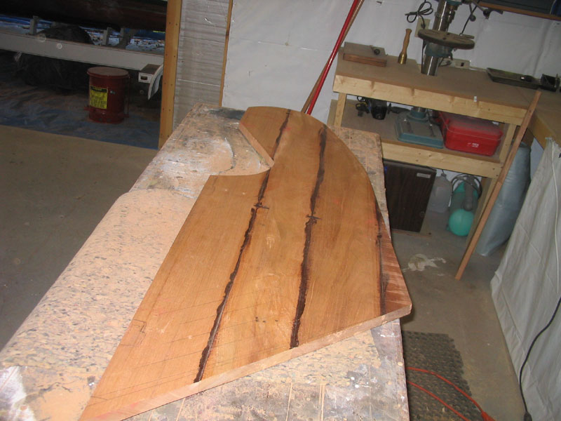
Later, I unclamped the blank and, using the old crescent-shaped rudder as a template, traced out an approximate shape on the blank. However, I changed the shape at the bottom end of the rudder, creating a straighter, more modern shape that flowed into the upper, curved shape of the original rudder at a tangent point about halfway up the back of the blade. After much consideration, and a few changes to the angle at the bottom edge to ensure that the bottom was "kicked up" in relation to the bottom of the keel, I cut out the basic shape with a circular saw and a jig saw. |
 Next,
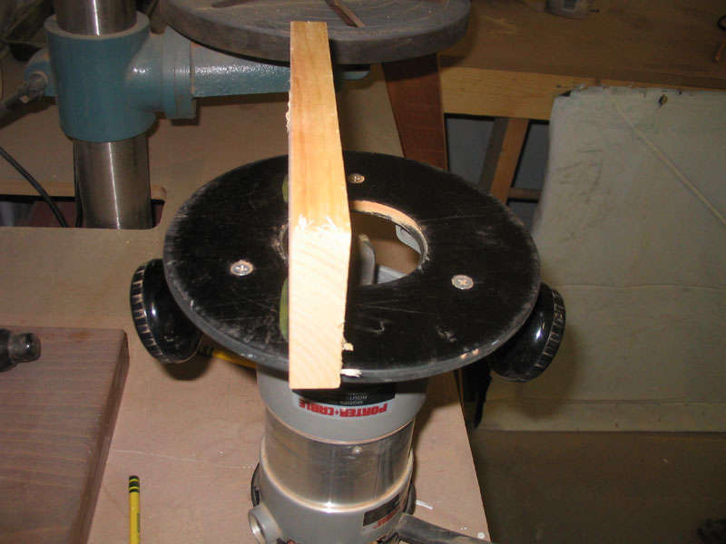
I set up to rout a 1" cove in the leading edge of the rudder blade to
accept the rudder shaft. I had had a new shaft made of Tobin
bronze, close in concept to the original but longer at the top end to
accommodate the deck changes. To partially recess the shaft in the
leading edge of the rudder, I installed a 1" cove bit in my router, and
attached a temporary stabilizing fence to the base plate with hot glue
to help guide and hold the router on the narrow 1" thick rudder blank. Next,
I set up to rout a 1" cove in the leading edge of the rudder blade to
accept the rudder shaft. I had had a new shaft made of Tobin
bronze, close in concept to the original but longer at the top end to
accommodate the deck changes. To partially recess the shaft in the
leading edge of the rudder, I installed a 1" cove bit in my router, and
attached a temporary stabilizing fence to the base plate with hot glue
to help guide and hold the router on the narrow 1" thick rudder blank. |
|
|
|
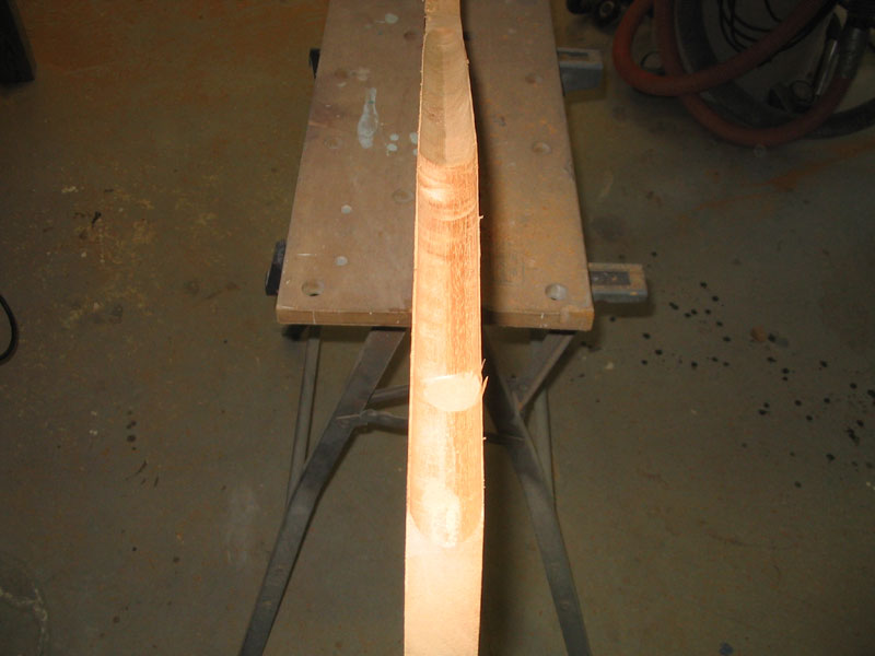
Then, in two passes, I routed out the cove to an appropriate depth of about half the thickness of the rudder shaft. |
|
|
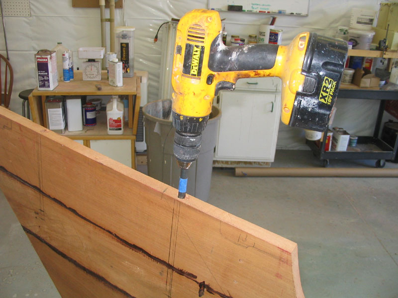 To
strengthen the rudder and help hold the planks together, I decided to
install several lengths of threaded rod through the blade.
Installation was a multi-step process. First, I carefully drilled
a 1/4" hole into the rudder from one edge, using a long bit that I had.
Once I had this pilot hole drilled, I enlarged it to 1/2" with a larger,
long bit, bottoming out the bit to maximum depth. To
strengthen the rudder and help hold the planks together, I decided to
install several lengths of threaded rod through the blade.
Installation was a multi-step process. First, I carefully drilled
a 1/4" hole into the rudder from one edge, using a long bit that I had.
Once I had this pilot hole drilled, I enlarged it to 1/2" with a larger,
long bit, bottoming out the bit to maximum depth. |
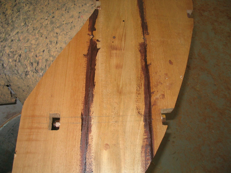 To
finish off the through holes, I returned the rudder over in the vice and
repeated the process on the other side. The result was not unlike
the two teams that dug the Channel Tunnel, working independently from
both sides and hoping to meet in the middle. With minor
adjustments, I was able to meet successfully. I repeated this
process for four threaded rods: two that passed all the way
through the rudder lengthwise, and two additional ones that dead-ended
in the center of the rudder. To
finish off the through holes, I returned the rudder over in the vice and
repeated the process on the other side. The result was not unlike
the two teams that dug the Channel Tunnel, working independently from
both sides and hoping to meet in the middle. With minor
adjustments, I was able to meet successfully. I repeated this
process for four threaded rods: two that passed all the way
through the rudder lengthwise, and two additional ones that dead-ended
in the center of the rudder. |
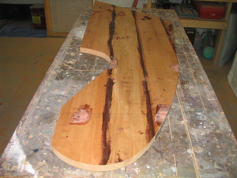
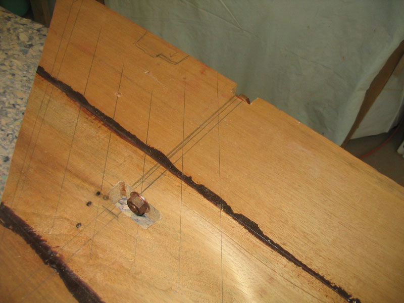 Next,
I notched the rudder to accept some nuts and washers at the ends of the
holes, and installed lengths of silicon bronze threaded rod in each
hole, equipped with a nut and washer at each end. After tightening
the bolts, I taped over one side of the openings and filled the notches
with epoxy filler, overfilling each hole somewhat so that I could sand
it smooth later. Next,
I notched the rudder to accept some nuts and washers at the ends of the
holes, and installed lengths of silicon bronze threaded rod in each
hole, equipped with a nut and washer at each end. After tightening
the bolts, I taped over one side of the openings and filled the notches
with epoxy filler, overfilling each hole somewhat so that I could sand
it smooth later. |
|
|
| Back to Main Menu> |