
|
|
~MENU~ |
| Home |
| The Concept |
| The Boat |
| Bringing Her Home |
|
Weekly Progress Log |
|
Daysailor Projects |
| The Boat Barn |
| Resources |
| Other Sites |
| Email Tim |
|
|
|
Systems: Diesel Engine: Engine Foundation |
|
Engine Base Template In February 2004, I built a plywood engine template so that I could visualize the engine shape and position. At the time, the template was important in assisting me to determine the eventual height of the cockpit deck so that I could make some cuts in the newly-installed bulkheads.
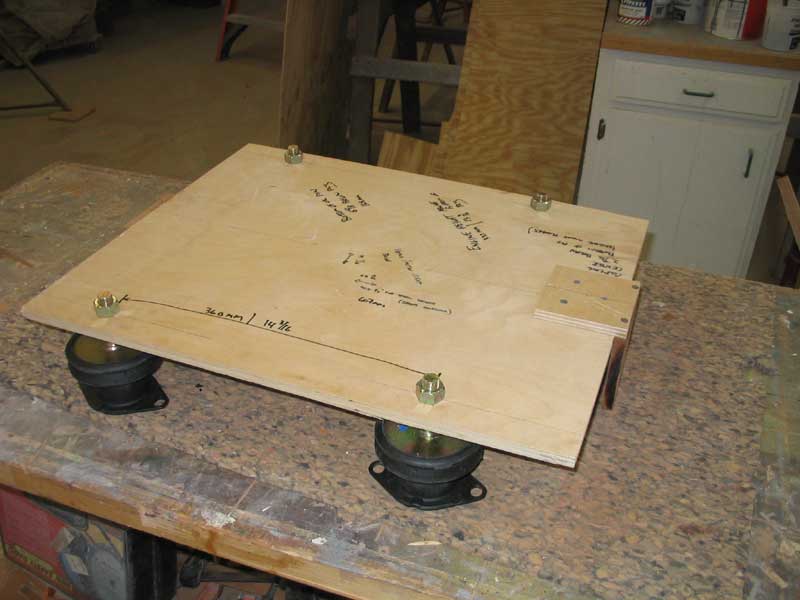
Now, in March 2005, it was time to actually begin constructing my engine foundations. My Vetus M2.06 diesel engine had arrived, and after confirming that the actual measurements gibed with those in the drawings (from which I had built the template), I proceeded with the preliminary work required to build the foundations. First, though, I installed the supplied Vetus flexible engine mounts onto the platform, carefully locating each hole in the appropriate place. |
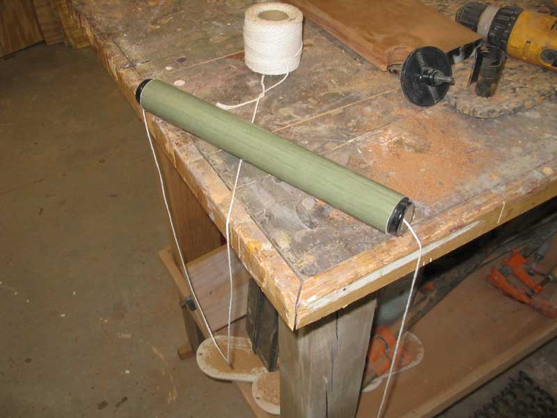
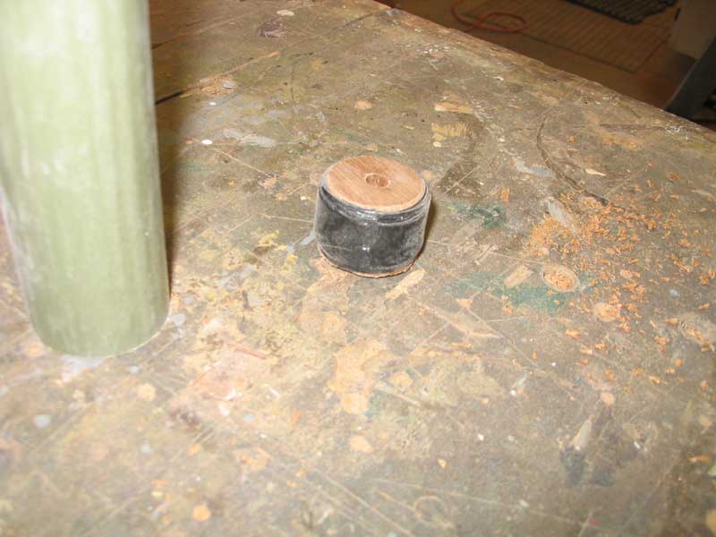 Next,
I prepared to install an alignment string through the shaft log, which
represented the exact centerline of the propeller shaft. Since I had
removed the old stern tube earlier, slated for replacement, I cut a length
of the new fiberglass tubing longer than required, and cut two temporary
plugs for the ends to help center the string in the opening. To make
each plug fit tightly, I wrapped the edges in black electrical tape for a
snug fit inside the fiberglass tubing. I couldn't help thinking that
my arrangement resembled a pipe bomb. I secured the bitter end of
the string with tape on the outside. Next,
I prepared to install an alignment string through the shaft log, which
represented the exact centerline of the propeller shaft. Since I had
removed the old stern tube earlier, slated for replacement, I cut a length
of the new fiberglass tubing longer than required, and cut two temporary
plugs for the ends to help center the string in the opening. To make
each plug fit tightly, I wrapped the edges in black electrical tape for a
snug fit inside the fiberglass tubing. I couldn't help thinking that
my arrangement resembled a pipe bomb. I secured the bitter end of
the string with tape on the outside. |
|
|
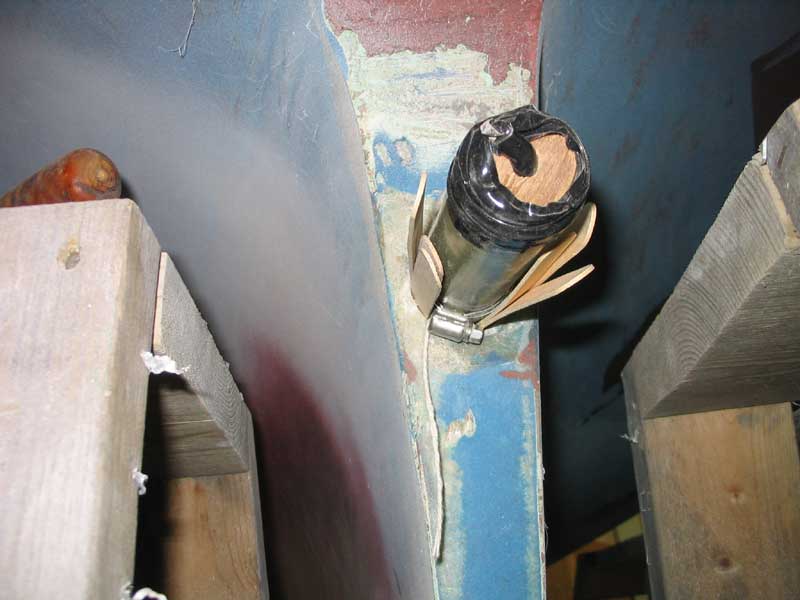 I
continued by installing the length of fiberglass tube in the oversized
hole in the keel deadwood. I pinned it in place with some wooden
stir sticks (tongue depressors) and roughly aligned the tube by eye.
While I wanted my initial engine template alignment and foundation
construction to be as accurate as possible, I had some leeway, since I
planned to actually delay installing the stern tube until the engine was
bolted in place. Then, with a length of shafting, I could actually
align the stern tube perfectly to the engine, rather than the other way
around. But that's for later. I
continued by installing the length of fiberglass tube in the oversized
hole in the keel deadwood. I pinned it in place with some wooden
stir sticks (tongue depressors) and roughly aligned the tube by eye.
While I wanted my initial engine template alignment and foundation
construction to be as accurate as possible, I had some leeway, since I
planned to actually delay installing the stern tube until the engine was
bolted in place. Then, with a length of shafting, I could actually
align the stern tube perfectly to the engine, rather than the other way
around. But that's for later. |
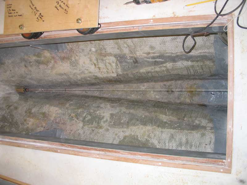 To
secure the forward end of the string, I borrowed a metal door handle from
a fixture in the shop and temporarily screwed it to the bulkhead at the
forward end of the engine room, after eyeballing the proper height.
The handle gave me some side-to-side adjustment leeway for the string.
Then, I secured the string in place, ensuring that it ran through the dead
center of the temporary shaft log. To
secure the forward end of the string, I borrowed a metal door handle from
a fixture in the shop and temporarily screwed it to the bulkhead at the
forward end of the engine room, after eyeballing the proper height.
The handle gave me some side-to-side adjustment leeway for the string.
Then, I secured the string in place, ensuring that it ran through the dead
center of the temporary shaft log. |
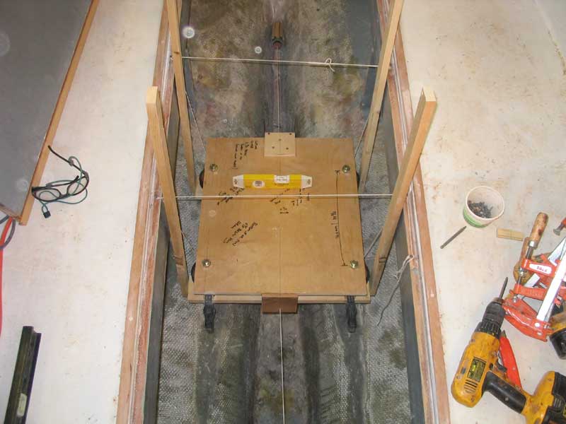
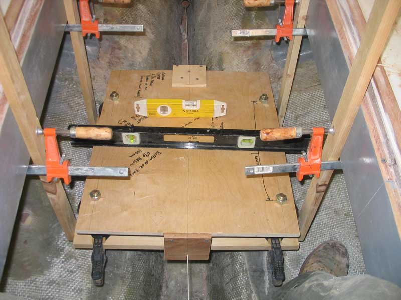
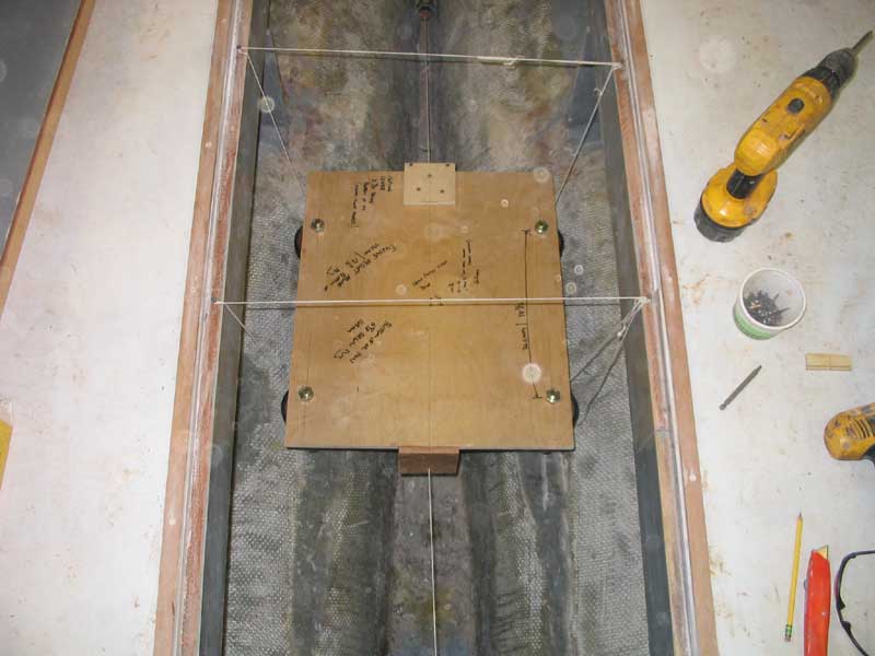 Next,
I prepared to install the engine template over the string. The
template included holes that represented the centerline of the shaft, so
by running the string through these holes (which contained slots at the
bottom to allow the string to be slipped easily in and out) I ensured
proper alignment and placement. To help hold the template in place,
I rigged up a pair of simple slings, made of string, from the deck beams
above--a most convenient arrangement in this case. By adjusting the
strings, it was quite straightforward to position the template properly,
with the alignment string running through the center of each hole in the
template. Next,
I prepared to install the engine template over the string. The
template included holes that represented the centerline of the shaft, so
by running the string through these holes (which contained slots at the
bottom to allow the string to be slipped easily in and out) I ensured
proper alignment and placement. To help hold the template in place,
I rigged up a pair of simple slings, made of string, from the deck beams
above--a most convenient arrangement in this case. By adjusting the
strings, it was quite straightforward to position the template properly,
with the alignment string running through the center of each hole in the
template. |
|
|
|
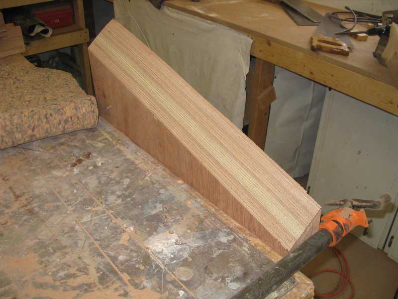
In the morning, I unclamped the blanks and cleaned up one of the edges with a belt sander; then, I ran the pieces through my tablesaw for a consistent size and for straight edges all around. When the two blanks were cleaned up and free from excess resin, I was ready to continue with installation procedures. |
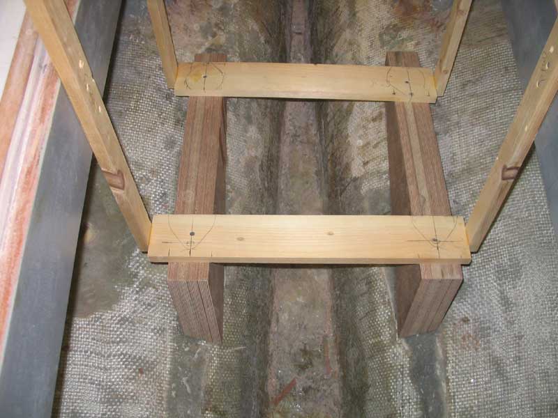
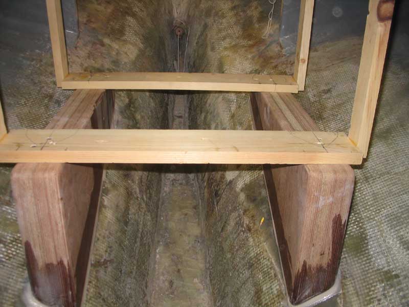
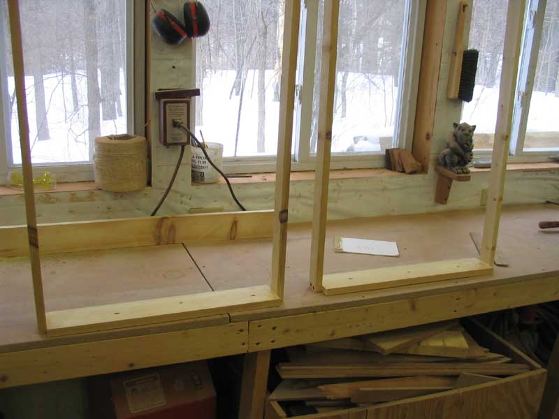 To
make it easier to visualize and measure the distance beneath the mounts,
which equated to the height of the foundations required, I fabricated a
pair of simple pine brackets, consisting of a flat horizontal piece (which
would fit beneath the mounts on the template) and a pair of vertical
supports that I could clamp or screw to the deck beams. With these,
and quite a bit of fussing around to ensure that the alignment remained
proper, I could support the engine template in place and remove the
strings. To
make it easier to visualize and measure the distance beneath the mounts,
which equated to the height of the foundations required, I fabricated a
pair of simple pine brackets, consisting of a flat horizontal piece (which
would fit beneath the mounts on the template) and a pair of vertical
supports that I could clamp or screw to the deck beams. With these,
and quite a bit of fussing around to ensure that the alignment remained
proper, I could support the engine template in place and remove the
strings. |
|
|
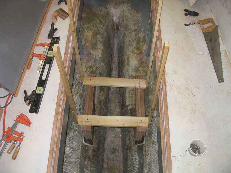
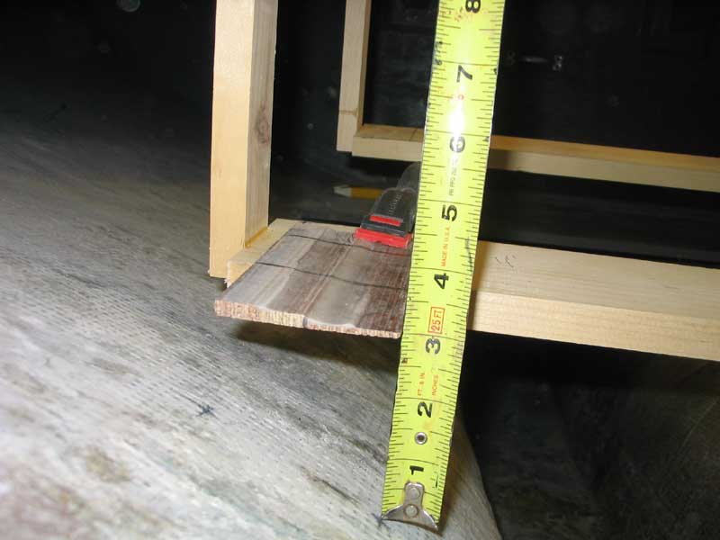 Then,
by measuring the distance from the top of the new pine supports (equal to
the bottom of the flexible mounts) to the hull beneath at both bow and
stern, and at a predetermined width at each end from the centerline of the
flexible mounts' boltholes (3", or 1-1/2" either side--the same as the
thickness of my built-up engine foundation blanks), I could determine the
rough dimensions of the foundations needed. To aid in measuring, I
secured a thin strip of scrap over the top of the pine supports, and
measured to the bottom of the scrap as seen here. Then,
by measuring the distance from the top of the new pine supports (equal to
the bottom of the flexible mounts) to the hull beneath at both bow and
stern, and at a predetermined width at each end from the centerline of the
flexible mounts' boltholes (3", or 1-1/2" either side--the same as the
thickness of my built-up engine foundation blanks), I could determine the
rough dimensions of the foundations needed. To aid in measuring, I
secured a thin strip of scrap over the top of the pine supports, and
measured to the bottom of the scrap as seen here. |
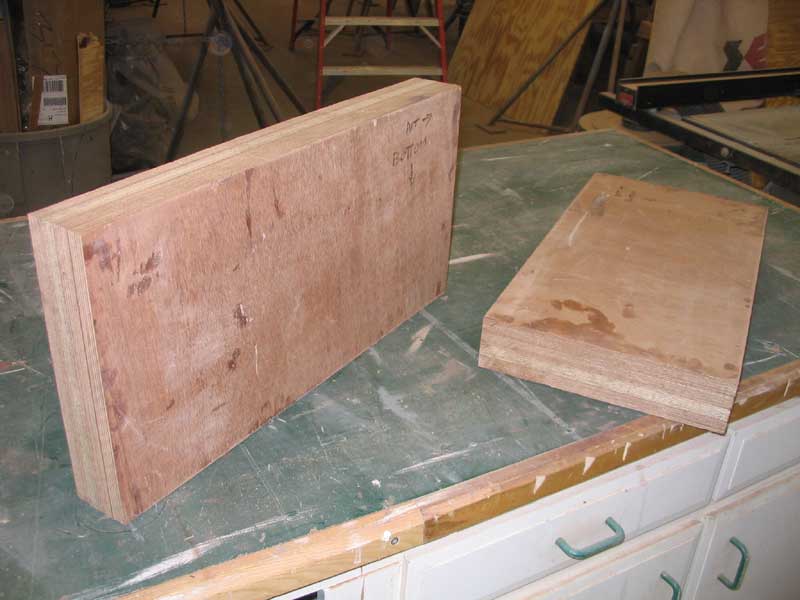
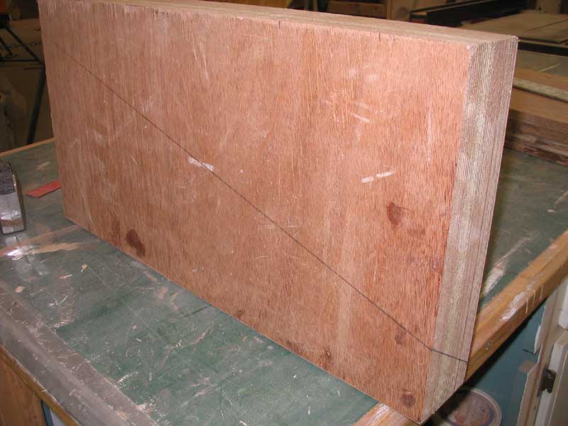 After
marking the cut lines on the blanks, I cut off the waste section with a
circular saw, making two passes (one from each side) to complete the cut.
Then, I fine-tuned the cuts with a belt sander. Test fitting was
made easier since the blanks should have fit directly and tightly beneath
the pine supports that were still in place. My first test fit showed
that I had to remove material, and so it continued through several test
fittings on both sides. I carefully removed material with the belt sander
as needed, until the foundation blanks fit properly in the space beneath
the pine supports. After
marking the cut lines on the blanks, I cut off the waste section with a
circular saw, making two passes (one from each side) to complete the cut.
Then, I fine-tuned the cuts with a belt sander. Test fitting was
made easier since the blanks should have fit directly and tightly beneath
the pine supports that were still in place. My first test fit showed
that I had to remove material, and so it continued through several test
fittings on both sides. I carefully removed material with the belt sander
as needed, until the foundation blanks fit properly in the space beneath
the pine supports. |
|
|
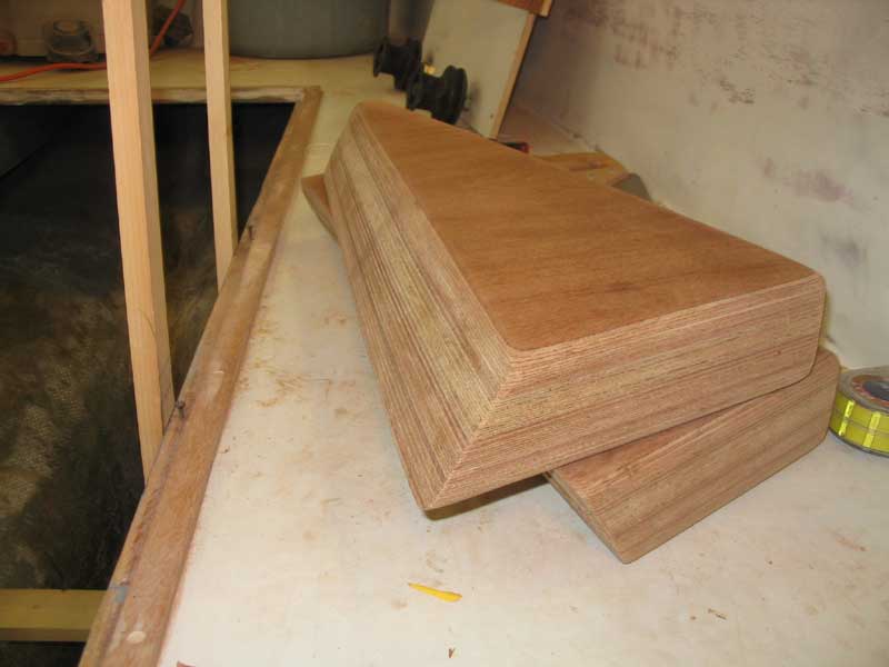 With
each blank properly sized, I used a router and two different bits to ease
the various edges for ease of later glasswork: a 1/2" radius on the
vertical edges, and a 1/4" radius (to avoid removing too much of the flat
top surface where the engine mounts would rest) on the upper two edges.
After some minor sanding, the foundations were ready for installation. With
each blank properly sized, I used a router and two different bits to ease
the various edges for ease of later glasswork: a 1/2" radius on the
vertical edges, and a 1/4" radius (to avoid removing too much of the flat
top surface where the engine mounts would rest) on the upper two edges.
After some minor sanding, the foundations were ready for installation. |
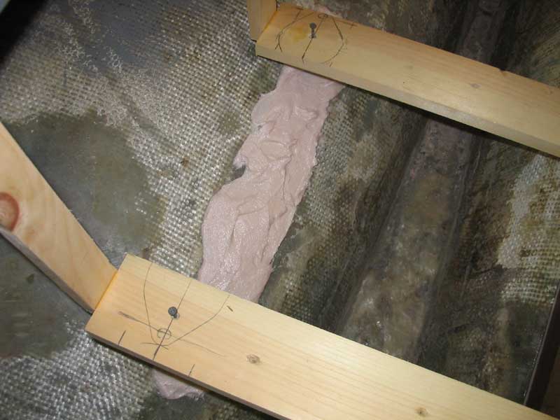 I
set the foundations in a bed of thickened epoxy against the hull, applying
a thick amount that I knew would fill all voids beneath the mounts.
It was convenient to use the pine supports to hold the foundations in
place during gluing; I drove two screws through the pine and into the
foundations, holding them securely. I created fillets as needed on
the edges of the intersections, which would make later glasswork easier.
Then, I left the foundations to cure overnight before proceeding. I
set the foundations in a bed of thickened epoxy against the hull, applying
a thick amount that I knew would fill all voids beneath the mounts.
It was convenient to use the pine supports to hold the foundations in
place during gluing; I drove two screws through the pine and into the
foundations, holding them securely. I created fillets as needed on
the edges of the intersections, which would make later glasswork easier.
Then, I left the foundations to cure overnight before proceeding. |
|
|
|
Please click here to continue.>
|