|
|
~MENU~ |
| Home |
| The Concept |
| The Boat |
| Bringing Her Home |
|
Weekly Progress Log |
|
Daysailor Projects |
| The Boat Barn |
| Resources |
| Other Sites |
| Email Tim |
|
|
|
From a Bare Hull: Deck Beams |
|
|
|
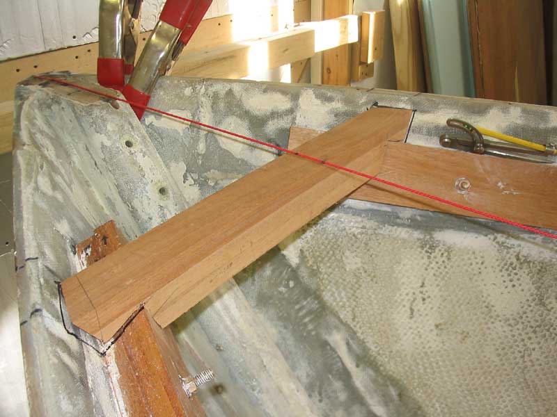
Now all I had to do was trim the ends of each beam to fit in the space between the hull sides, supported at the proper height by the sheer clamp. In theory, this seemed simple enough, but I soon found that it was far more complex than anticipated--a fact that was further complicated by the fact that I had to learn as I went. |
|
Rather than digress into a detailed description of the fitting process, I would choose to refer you to the myriad texts on the subject. The book I have that has been of great use during several portions of this project is How to Build a Wooden Boat, by David C. (Bud) McIntosh. Suffice it to say that each beam, particularly those near the more dramatic curves of the bow, required a number of cuts in order to fit properly: angle cuts on each end, to match both the curvature of the sheer towards the stem as well as the flare of the hull, and birds' mouth cuts on the undersides of the beams so that the beams rest flush on the sheer clamp and at the appropriate height--which, in this case, meant about 3/4" below the height of the sheer to account for the 2-layer plywood decking. |
|
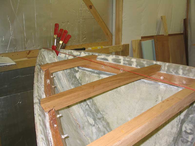
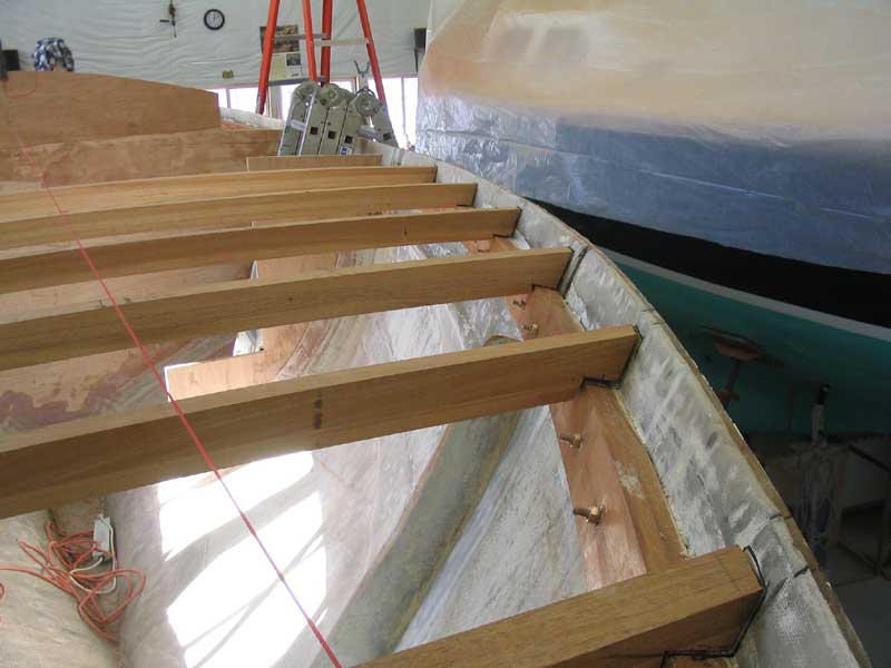
Note that a more extreme amount of the first two beams had to be removed in order to fit at the proper height around the sheer clamp. Because of the difficulty in bending the clamp down to the proper marks at the most forward extreme, it ended up slightly higher than ideal. Had the beams featured a longer span, where the full strength of the laminations would be needed, I would have modified the clamp accordingly, or taken whatever steps were necessary in order to ensure that it bent to the proper line, but in this case I didn't worry about it. Starting with the third beam from the bow, the clamp was located at its proper marks, so each additional beam would have only a small amount cut from the bottom in order to fit properly. |
 Later,
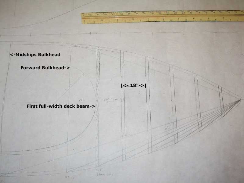
I finished fitting the full-width beams that support the foredeck.
The aftermost of these beams corresponds with the forward edge of the
carlin that will define and support the cabin trunk (see
the drawing at the top of this page);
the curved carlin will be tangent to this final deck beam once it is
installed. With the exception of one or two full-width beams at the
stern of the boat, aft of the cockpit, all remaining beams were to be
shorter lengths, spanning the distance between the hull and the
yet-to-be-installed carlines. Later,
I finished fitting the full-width beams that support the foredeck.
The aftermost of these beams corresponds with the forward edge of the
carlin that will define and support the cabin trunk (see
the drawing at the top of this page);
the curved carlin will be tangent to this final deck beam once it is
installed. With the exception of one or two full-width beams at the
stern of the boat, aft of the cockpit, all remaining beams were to be
shorter lengths, spanning the distance between the hull and the
yet-to-be-installed carlines. |
|
|
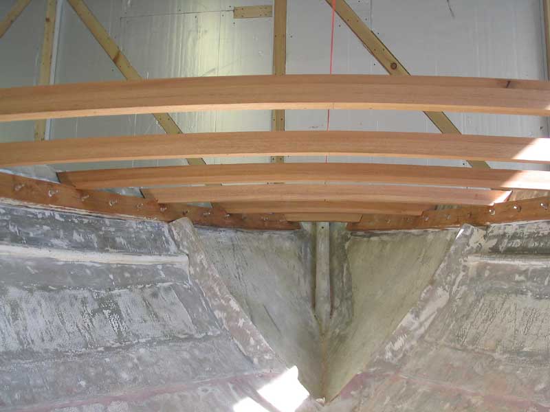
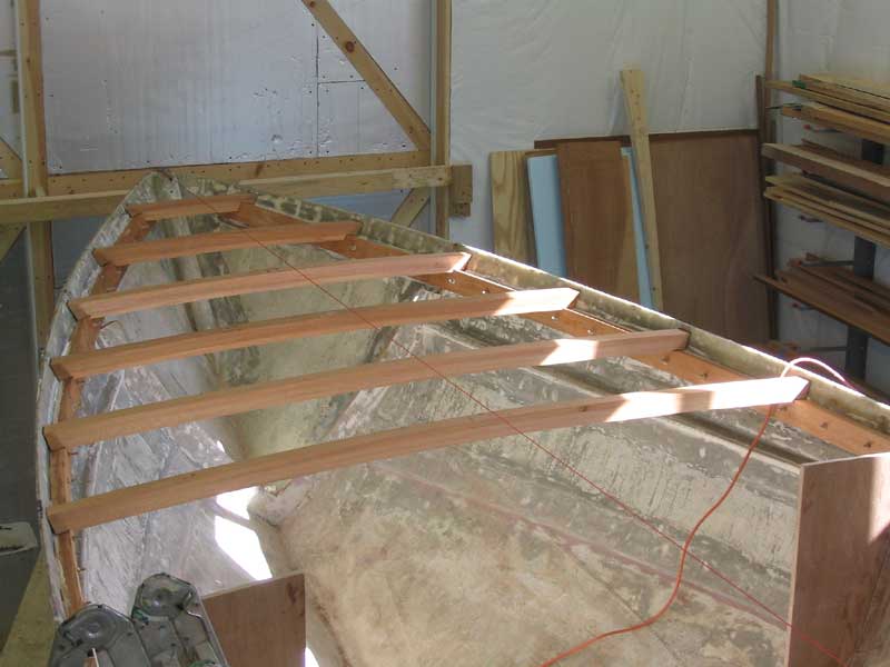
 With
the first six deck beams roughed in, the ultimate appearance of the deck
began to become more clear. There were a number of small jobs that I
needed to complete before installing the beams permanently, so I left them
loosely in place while I began other tasks. Before final
installation, the exposed beams will require additional detailing,
including sanding and a bead or roundover detail on the bottom edges. With
the first six deck beams roughed in, the ultimate appearance of the deck
began to become more clear. There were a number of small jobs that I
needed to complete before installing the beams permanently, so I left them
loosely in place while I began other tasks. Before final
installation, the exposed beams will require additional detailing,
including sanding and a bead or roundover detail on the bottom edges.
Before anyone writes, please note that in the photo to the right, you will see what appear to be huge gaps between the beams and the sheer clamp. While there is some play, the reason the gaps look big is because I marked around the edges of all the beams with a black marker to help locate them later, during final installation, and the marker also left marks on the beams themselves, creating the photographic illusion of a gaping opening. |