|
|
~MENU~ |
| Home |
| The Concept |
| The Boat |
| Bringing Her Home |
|
Weekly Progress Log |
|
Daysailor Projects |
| The Boat Barn |
| Resources |
| Other Sites |
| Email Tim |
|
|
|
From a Bare Hull: The Cockpit (Page 8) |
|
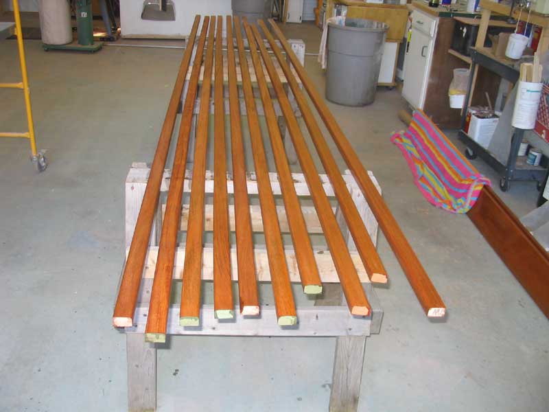
Cockpit Benches For the cockpit, I envisioned simple varnished mahogany benches, made from planks secured in place on brackets beneath as required. To that end, one day I milled up a number of planks for the job, each just over 3" in width. Figuring on 1/4" gaps between the planks, plus a 7/8" trim piece at the outer end, I came up with a total bench width of just under 14", which jibed with what I had figured would be an appropriate width. |
|
Unfortunately, I discovered after milling all the boards that the curvature at the sides of the cockpit was far greater than my memory had allowed me to remember; with a straightedge spanning the length of the cockpit, the curvature was nearly 6" deep at its furthest extent. I feared that this would mean that it would be impossible to bend the boards into place to follow the curvature, creating a quandary for me. For now, I placed the milled planks aside, and moved on to the seat supports. |
|
|
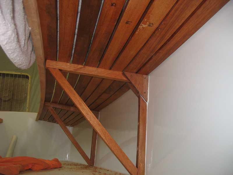
 Eventually,
I came up with a simple brace made from 1" x 7/8" stock, with an
inverted L-shaped bracket supported by an angled brace running between
the legs. This design, I thought, would also eliminate the need
for a vertical let at the outer edge, and would be easy to build.
To strengthen the brackets, I decided to use a small plywood gusset at
the inner corner. Eventually,
I came up with a simple brace made from 1" x 7/8" stock, with an
inverted L-shaped bracket supported by an angled brace running between
the legs. This design, I thought, would also eliminate the need
for a vertical let at the outer edge, and would be easy to build.
To strengthen the brackets, I decided to use a small plywood gusset at
the inner corner. |
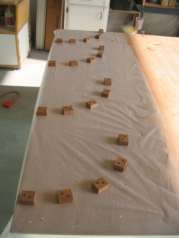
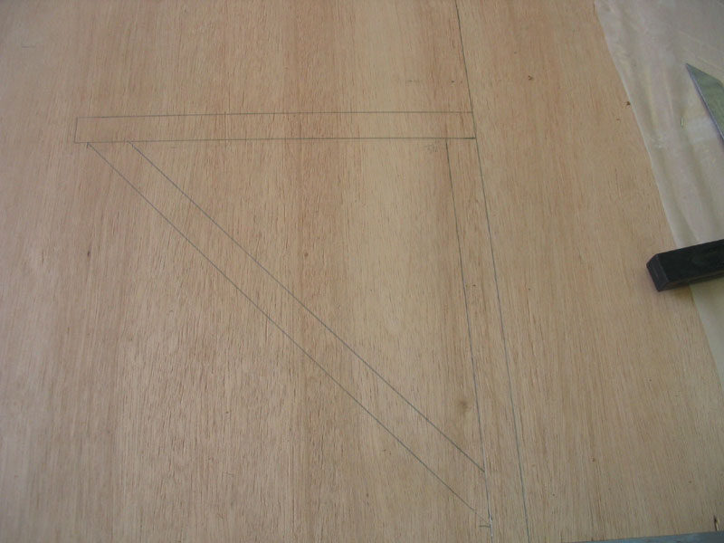
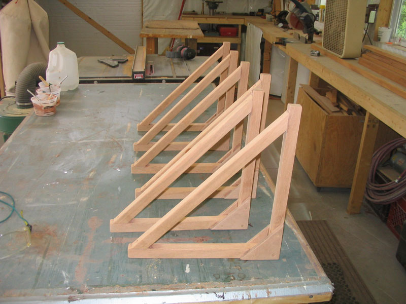 After
milling the various pieces, I traced them out on a piece of plywood, and
then used the pattern as a guide to help me glue up the braces to the
correct shape. Using resorcinol glue, I glued up the braces, using
bronze screws to hold the angle braces and gussets in position. After
milling the various pieces, I traced them out on a piece of plywood, and
then used the pattern as a guide to help me glue up the braces to the
correct shape. Using resorcinol glue, I glued up the braces, using
bronze screws to hold the angle braces and gussets in position. |
|
After the glue cured, I sanded the braces smooth and applied a sealer coat of varnish before installation. To install the braces, I began with some layout. I immediately discovered that I had slightly miscalculated my height, and had failed to take into account the fact that the cockpit was shallower at the aft end, a combination of a pitched cockpit sole and the sheerline of the boat and deck working together to reduce the depth of the well. At the existing bracket height, clearance for the seat slats below the coaming boards would have been an issue. I had also planned to raise the bottoms of the brackets 1" off the sole, but even with the braces down the remaining inch I didn't have enough clearance with which to be comfortable. |
 Fortunately,
I had enough excess length built into the bottom of my braces that I
could trim 3/4" off the bottom without harming the structural integrity.
I also trimmed a slight angle at the after side of the brace to allow it
to rest comfortably over the cove at the bottom of the cockpit well
where it met the sides. In the new configuration, there was
adequate room at the after end, so I pressed on with the installation. Fortunately,
I had enough excess length built into the bottom of my braces that I
could trim 3/4" off the bottom without harming the structural integrity.
I also trimmed a slight angle at the after side of the brace to allow it
to rest comfortably over the cove at the bottom of the cockpit well
where it met the sides. In the new configuration, there was
adequate room at the after end, so I pressed on with the installation. |
|
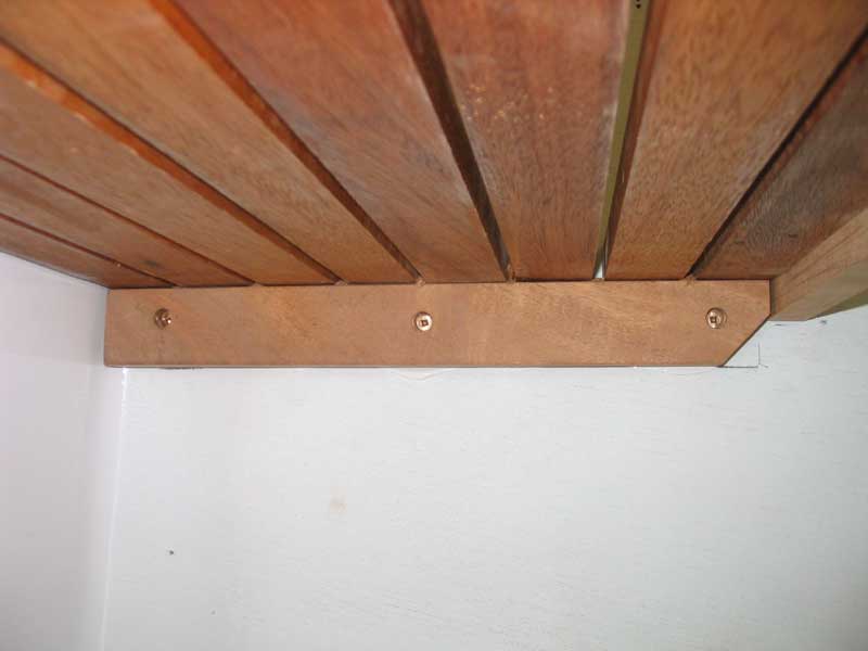
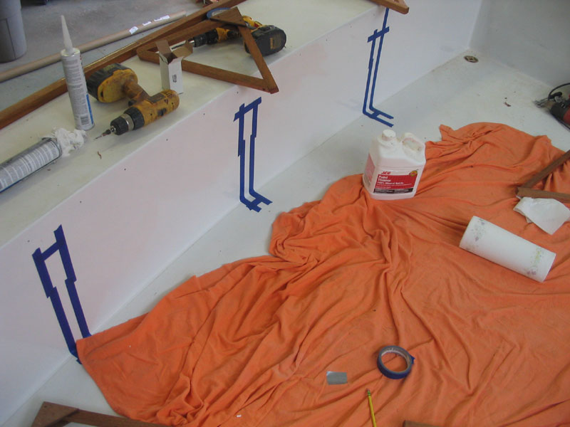
Locating the braces approximately three feet apart along the sides of the well, I marked a plumb line and then traced out the shape of the brace using the plumb line as a guide. Then, I applied masking tape around the outline to help with cleanup of adhesive later on. Once all six brace locations were marked, I continued with installation. |
 I
installed each brace with 5200 adhesive for a permanent and strong bond,
and with three bronze screws driven through the back leg of the brace
and into the plywood cockpit side. The cockpit seats would take a
lot of abuse during normal sailing of the boat, with people sitting,
stepping and otherwise bumping the seats, so I felt the superior
strength qualities of 5200 were merited. I considered
through-bolting, but I only had access from behind to two of the three
supports on each side, so after consideration, I elected to use the 5200
and screws to hold it while the adhesive cured. I
installed each brace with 5200 adhesive for a permanent and strong bond,
and with three bronze screws driven through the back leg of the brace
and into the plywood cockpit side. The cockpit seats would take a
lot of abuse during normal sailing of the boat, with people sitting,
stepping and otherwise bumping the seats, so I felt the superior
strength qualities of 5200 were merited. I considered
through-bolting, but I only had access from behind to two of the three
supports on each side, so after consideration, I elected to use the 5200
and screws to hold it while the adhesive cured. |
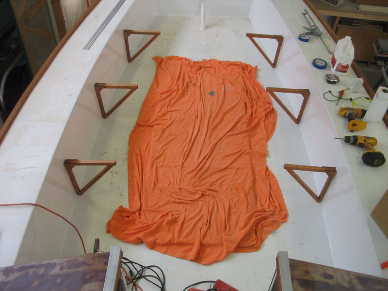 I
was not shy with the 5200, and was pleased when it oozed out along the
edges when the screws were applied. Once all six braces were in, I
cleaned up the excess squeezeout, and left the braces to cure for
several days before beginning any serious work. around them. I
was not shy with the 5200, and was pleased when it oozed out along the
edges when the screws were applied. Once all six braces were in, I
cleaned up the excess squeezeout, and left the braces to cure for
several days before beginning any serious work. around them. |
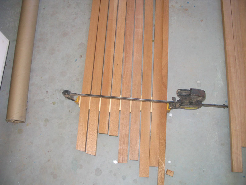 After
mulling the issue for a time, and even trying a test fit of the planks
(no way would they bend), I elected to cut each 3" plank in half,
creating double the number of strips, each just under 1-1/2" wide.
After test ripping one plank, I tried the fit up in the boat, and was
pleased to find that the new, narrower strip bent easily to the
curvature required. Mocking up the strips with 1/4" spacers showed
that the width should still be OK, so therefore I continued ripping the
planks. Afterwards, I used a router to round over the top edges
with a 1/4" roundover bit, and sanded the strips smooth with 220 grit. After
mulling the issue for a time, and even trying a test fit of the planks
(no way would they bend), I elected to cut each 3" plank in half,
creating double the number of strips, each just under 1-1/2" wide.
After test ripping one plank, I tried the fit up in the boat, and was
pleased to find that the new, narrower strip bent easily to the
curvature required. Mocking up the strips with 1/4" spacers showed
that the width should still be OK, so therefore I continued ripping the
planks. Afterwards, I used a router to round over the top edges
with a 1/4" roundover bit, and sanded the strips smooth with 220 grit. |
 After
applying some sealer varnish to all sides of the cockpit slats, I
prepared for installation. I measured along the curve at the
outside of the cockpit to determine the length, and used a bevel gauge
to determine the angle at the after end; the forward end would be square
against the bulkhead. After
applying some sealer varnish to all sides of the cockpit slats, I
prepared for installation. I measured along the curve at the
outside of the cockpit to determine the length, and used a bevel gauge
to determine the angle at the after end; the forward end would be square
against the bulkhead. |
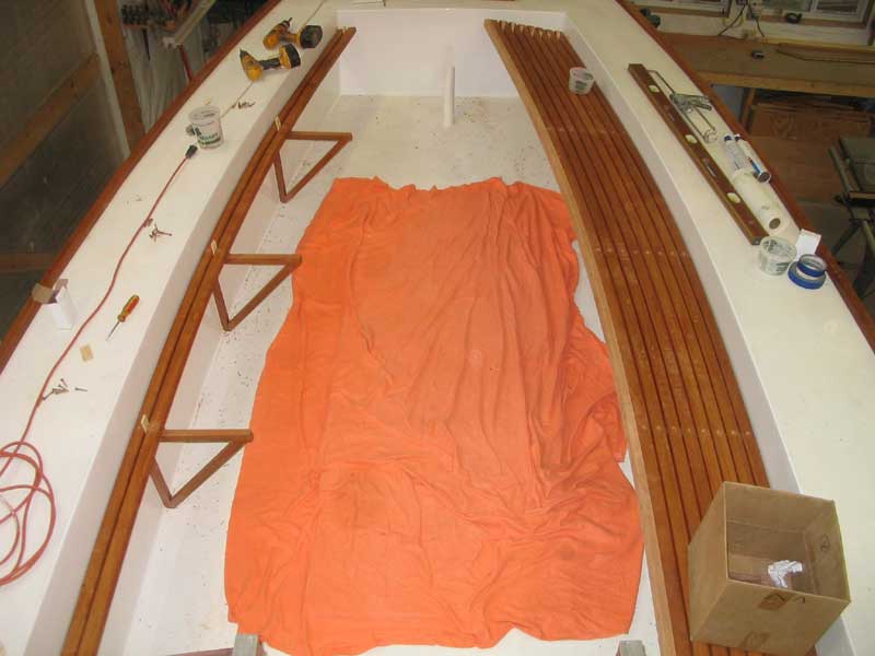
 With
each strip in turn cut to the proper length, installation was easy.
The pieces bent into the curvature nicely, and I used some 1/4" spacers
(left over from the ceiling project) to hold the slats at the correct
distance from the cockpit walls and from each other. Since I
didn't know exactly where the ends of the slats would fall, height-wise,
I retrained from installing cleats at the forward and after bulkheads
until later. With
each strip in turn cut to the proper length, installation was easy.
The pieces bent into the curvature nicely, and I used some 1/4" spacers
(left over from the ceiling project) to hold the slats at the correct
distance from the cockpit walls and from each other. Since I
didn't know exactly where the ends of the slats would fall, height-wise,
I retrained from installing cleats at the forward and after bulkheads
until later. |
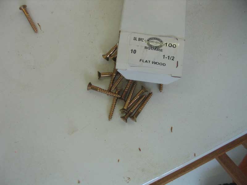
 I
installed each slat with a #10 x 1-1/2" bronze screw at each seat brace
location. This held the slats in the appropriate curve, along with
the spacers at the ends, and the process went quickly, other than a lot
of up and down the ladder to cut each piece. I didn't dare cut all
pieces in advance to one length, as I was unsure how the lengths would
pan out. (As it happened, a single measurement would have been
fine for all pieces). I installed all eight slats on each side of
the cockpit, and then added a final piece on the inside edge, screwing a
1-1/2" strip to the inside of the final slat to provide a finished
appearance and add the illusion of additional thickness from inside the
cockpit. I
installed each slat with a #10 x 1-1/2" bronze screw at each seat brace
location. This held the slats in the appropriate curve, along with
the spacers at the ends, and the process went quickly, other than a lot
of up and down the ladder to cut each piece. I didn't dare cut all
pieces in advance to one length, as I was unsure how the lengths would
pan out. (As it happened, a single measurement would have been
fine for all pieces). I installed all eight slats on each side of
the cockpit, and then added a final piece on the inside edge, screwing a
1-1/2" strip to the inside of the final slat to provide a finished
appearance and add the illusion of additional thickness from inside the
cockpit. |
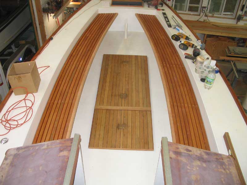 The
transformation of the cockpit was immediate, as the slats truly
highlighted the nice curves of the cockpit as it extended aft. I
was pleased with the look. The
transformation of the cockpit was immediate, as the slats truly
highlighted the nice curves of the cockpit as it extended aft. I
was pleased with the look.
With the slats installed, I continued by installing cleats at the forward and aft ends of each seat, now that I could determine where the slats naturally fell. This was more challenging than I had anticipated, and the process took longer than I had expected, but after a couple hours the job was done. |
|
|
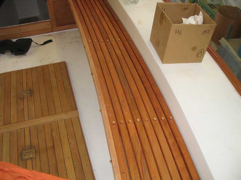 Finally,
I installed mahogany bungs in all the screw holes, using resorcinol
glue. When the clue cured, I pared away the excess bung with
chisel and block plane, and then sanded everything smooth. Finally,
I installed mahogany bungs in all the screw holes, using resorcinol
glue. When the clue cured, I pared away the excess bung with
chisel and block plane, and then sanded everything smooth.Now ongoing: lots of varnish!
|
|
Back to Main Menu> |