|
| |
|
From a Bare
Hull: The Cockpit
|
|
Cockpit
Understructure: Center Longitudinal Beams
Following the completion of the deck sheathing--plywood and fiberglass,
the next step was to build the cockpit. Only after the basic cockpit
was built could I move on to fairing the decks, since I planned to add
some additional fiberglass over the plywood edges in the cockpit area.
(More on that later.) |
|
 After
giving the matter some thought over several different days, I decided that
the cockpit sole would require some basic support in the form of two
curved beams (which mirrored the shape of the carlins above) at the edges,
and two straight longitudinal beams running the length of the cockpit, and
about 18" off center on each side. Since the cockpit was large, I
thought the center beams would need to be fairly deep in order to support
the deck without sags or bouncing. Since the edge beams would be
supported in part by the plywood sides of the cockpit, less depth of beam
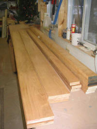
would be required there. I decided on 3" beams for the outer edges
and 5-1/2" beams for the two longitudinals, and milled up enough mahogany
lumber for the job. After
giving the matter some thought over several different days, I decided that
the cockpit sole would require some basic support in the form of two
curved beams (which mirrored the shape of the carlins above) at the edges,
and two straight longitudinal beams running the length of the cockpit, and
about 18" off center on each side. Since the cockpit was large, I
thought the center beams would need to be fairly deep in order to support
the deck without sags or bouncing. Since the edge beams would be
supported in part by the plywood sides of the cockpit, less depth of beam
would be required there. I decided on 3" beams for the outer edges
and 5-1/2" beams for the two longitudinals, and milled up enough mahogany
lumber for the job.
|
|
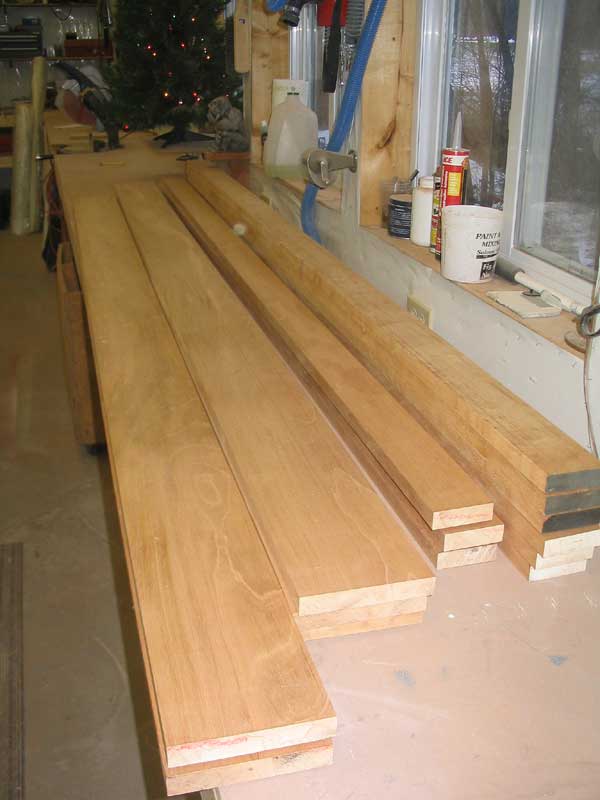
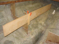
 Each
beam would require laminating, partly for strength and partly to make up
the required lengths from the shorter lumber on hand. Beginning with
7/8" thick planed stock, I decided that two laminations for each beam
would be adequate for the job. Each
beam would require laminating, partly for strength and partly to make up
the required lengths from the shorter lumber on hand. Beginning with
7/8" thick planed stock, I decided that two laminations for each beam
would be adequate for the job.
I started with the two deep center beams.
Since the cockpit opening was over 11' in length, I needed to join two
pieces of lumber for each lamination. This would be easy to
accomplish by simply staggering the joints in the two layers, and gluing
the whole arrangement together with epoxy. |
|
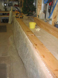 To
hold the pieces together while gluing--and also add extra strength when
complete--I decided to screw the pieces together with bronze screws during
the gluing process. For each of the two beams required, I applied
thickened epoxy resin to the boards, which I laid down on the bench with
plastic beneath. Then, after installing the top layer (with the
single joint staggered), I installed a pair of bronze screws every 6" on
center, and 1-1/2" in from each edge of the board. This pulled the
two layers together and held them in place. To
hold the pieces together while gluing--and also add extra strength when
complete--I decided to screw the pieces together with bronze screws during
the gluing process. For each of the two beams required, I applied
thickened epoxy resin to the boards, which I laid down on the bench with
plastic beneath. Then, after installing the top layer (with the
single joint staggered), I installed a pair of bronze screws every 6" on
center, and 1-1/2" in from each edge of the board. This pulled the
two layers together and held them in place.
I set the two new beams aside after cleaning
off the bulk of the spilled epoxy. The next morning, the two beams
were cured, and I moved on to installation. |
|
Locating the forward end of the beams in the boat was straightforward
enough, as I had previously marked a rough cockpit sole line on the
midships bulkhead, and also on the after bulkheads. However, the
after end required more work, since the beams would die out into the hull;
i.e. the curvature of the hull was such that by just aft of the cockpit,
the hull was higher than the tops of the new beams. Therefore, a
sharp angle cut would be required on the after end.
|
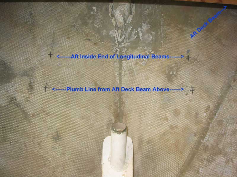
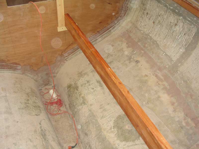
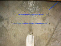 My first step was to locate the level of the new cockpit sole on the hull,
so that I could make some reference marks. Using a level with one
side resting on the small remnant of the old cockpit sole (fiberglassed to
the rudderpost and harking back to the main demolition) that I had
retained all this time specifically for the purpose of providing a general
reference mark for the cockpit sole, I transferred some marks to the hull
where the level just hit. I also transferred some plumb
lines down from the deck framing above, specifically at the aft corners of
the cockpit, as well as a centerline and marks signifying the space
between the beams, which equated to the open distance between the two
halves of the after bulkhead, or 23". My first step was to locate the level of the new cockpit sole on the hull,
so that I could make some reference marks. Using a level with one
side resting on the small remnant of the old cockpit sole (fiberglassed to
the rudderpost and harking back to the main demolition) that I had
retained all this time specifically for the purpose of providing a general
reference mark for the cockpit sole, I transferred some marks to the hull
where the level just hit. I also transferred some plumb
lines down from the deck framing above, specifically at the aft corners of
the cockpit, as well as a centerline and marks signifying the space
between the beams, which equated to the open distance between the two
halves of the after bulkhead, or 23". |
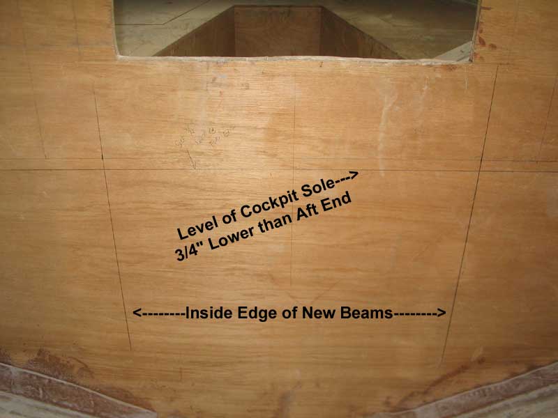
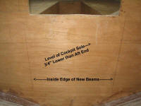 At the forward end, I made a new mark 3/4" below the level mark I had made
during a much earlier step in the process, some months before. The
new mark was intended to allow the cockpit sole to pitch forward for
drainage; I planned to mount scuppers at the forward end.
The sole was to be level side to side, of course. At the forward end, I made a new mark 3/4" below the level mark I had made
during a much earlier step in the process, some months before. The
new mark was intended to allow the cockpit sole to pitch forward for
drainage; I planned to mount scuppers at the forward end.
The sole was to be level side to side, of course.
|
 With marks now at both ends, I ran a string
between to sight the line and to also see where it ended up on the after
bulkhead, in case any cutting was necessary. It looked good, so I
removed the string, cut notches in the after bulkhead to match the
dimensions of the new beams (which would run through flush to the inboard
edge and top), and prepared for the next step. With marks now at both ends, I ran a string
between to sight the line and to also see where it ended up on the after
bulkhead, in case any cutting was necessary. It looked good, so I
removed the string, cut notches in the after bulkhead to match the
dimensions of the new beams (which would run through flush to the inboard
edge and top), and prepared for the next step. |
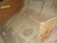
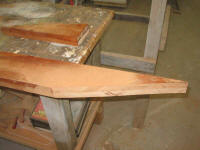
 In a perfect world, I would have placed the actual beam in position and
scribed the after end to fit. However, the beam blank was still over
length, and I could not yet determine the exact length of the beam; the
long beam was constrained by the amidships bulkhead and the curvature of
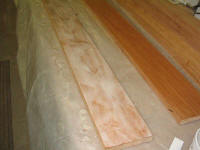
the hull aft. With no way to fit the beam blank into the proper
position for scribing, I used a scrap of plywood in its stead.
Securing the plywood on the top of the aft bulkhead, which had been
previously cut for the cockpit height shortly after initial installation,
I placed the aft corner on my new mark signifying the aftermost point of
the beam. Then, I set my dividers to 5-1/2"--the depth of the
beam--and scribed the hull onto the plywood pattern. In a perfect world, I would have placed the actual beam in position and
scribed the after end to fit. However, the beam blank was still over
length, and I could not yet determine the exact length of the beam; the
long beam was constrained by the amidships bulkhead and the curvature of
the hull aft. With no way to fit the beam blank into the proper
position for scribing, I used a scrap of plywood in its stead.
Securing the plywood on the top of the aft bulkhead, which had been
previously cut for the cockpit height shortly after initial installation,
I placed the aft corner on my new mark signifying the aftermost point of
the beam. Then, I set my dividers to 5-1/2"--the depth of the
beam--and scribed the hull onto the plywood pattern. |
 he line ended up being more or less straight, so it was easy to transfer
to the actual beams for cutting. Then, I cut the forward ends of the
beams off at approximately the correct length, plus a little bit for a
fudge factor. It was time for a test fit. To hold the forward
end of the beam in place, I screwed some temporary cleats to the bulkhead
in the appropriate places. he line ended up being more or less straight, so it was easy to transfer
to the actual beams for cutting. Then, I cut the forward ends of the
beams off at approximately the correct length, plus a little bit for a
fudge factor. It was time for a test fit. To hold the forward
end of the beam in place, I screwed some temporary cleats to the bulkhead
in the appropriate places. |
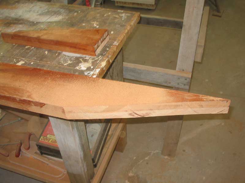
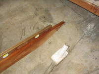
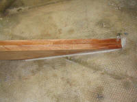
 When I was satisfied with the fit, I trimmed the beams to their final
length at the forward end and spent some time sanding the edges to remove
any epoxy spillout from the glueup the day before. I also chamfered
the bottom corners of the beam on each side, in keeping with my mission to
chamfer all the corners of structural items with which a boatowner might
someday come into contact. Not only was this a nice finishing touch,
it also protected the beams from accidental damage to the sharp corner. When I was satisfied with the fit, I trimmed the beams to their final
length at the forward end and spent some time sanding the edges to remove
any epoxy spillout from the glueup the day before. I also chamfered
the bottom corners of the beam on each side, in keeping with my mission to
chamfer all the corners of structural items with which a boatowner might
someday come into contact. Not only was this a nice finishing touch,
it also protected the beams from accidental damage to the sharp corner. |
|
|
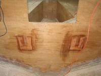 Next, I cut some final cleats to secure the forward ends of the beams.
I made the cleats of mahogany, and wrapped the three sides (not the top)
of the beam tightly. I cut a 35˚ bevel on the outer sides of each
cleat, since I planned to later install fiberglass tabbing to more
thoroughly secure the beams at the forward end; the bevels would allow the
glass to lay over the edges of the cleats as well. I installed the
cleats in a bed of thickened epoxy and screwed them to the bulkhead. Next, I cut some final cleats to secure the forward ends of the beams.
I made the cleats of mahogany, and wrapped the three sides (not the top)
of the beam tightly. I cut a 35˚ bevel on the outer sides of each
cleat, since I planned to later install fiberglass tabbing to more
thoroughly secure the beams at the forward end; the bevels would allow the
glass to lay over the edges of the cleats as well. I installed the
cleats in a bed of thickened epoxy and screwed them to the bulkhead. |
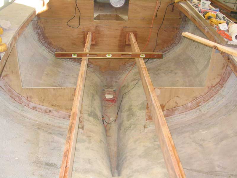
 I installed the new beams permanently using some thickened epoxy at the
mating areas (forward cleats, after bulkhead notches, and a thick bed at
the aft end where the beams intersected the hull). I also screwed
the beams to the after bulkhead with some #14 x 3" bronze screws. I
smoothed the epoxy into small fillets at each location, as I planned to
add fiberglass tabbing later on. After double-checking the level
from side to side (it was perfect), I left the beams to cure overnight. I installed the new beams permanently using some thickened epoxy at the
mating areas (forward cleats, after bulkhead notches, and a thick bed at
the aft end where the beams intersected the hull). I also screwed
the beams to the after bulkhead with some #14 x 3" bronze screws. I
smoothed the epoxy into small fillets at each location, as I planned to
add fiberglass tabbing later on. After double-checking the level
from side to side (it was perfect), I left the beams to cure overnight. |
|
Continue> |
|