| Circe
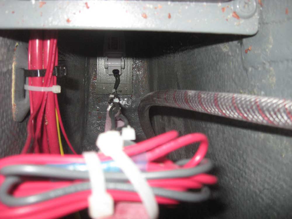
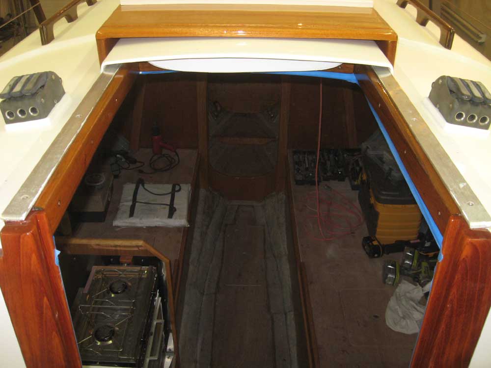
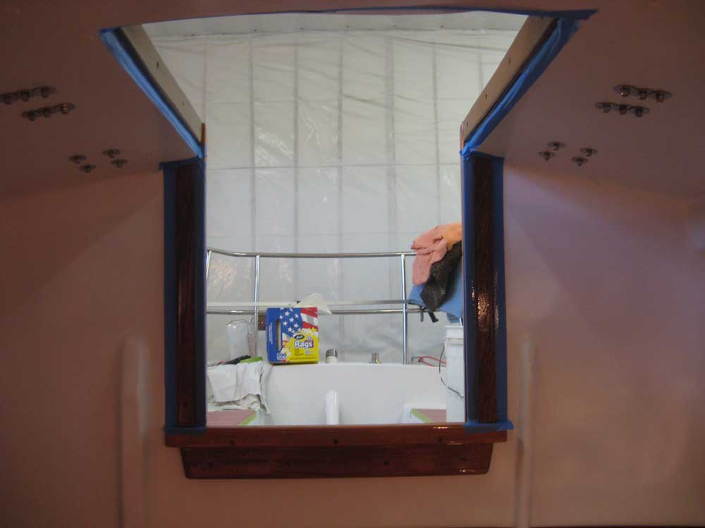
| Tuesday, March 9, 2010 I began with a couple left-over projects from yesterday. First, I pared off the excess bungs from the interior companionway trim, and lightly sanded as needed. Later, I'd apply a coat of varnish, but not till the end of the day. I finished up the door catch installation on the remaining cabinet doors, and installed a pair of latches on the electrical panel door to hold it in place. Next, I turned to the electric bilge pump. It took a while to run the requisite pair of wires along the wire bundle beneath the engine and forward to where the float switch would go, after which I made up the connections at the top of the float switch handle and, leaving a bundle of extra wire to allow the switch assembly to be pulled up and serviced, lowered the float switch into position and secured the top of the stick with a screw. |
|
|
|
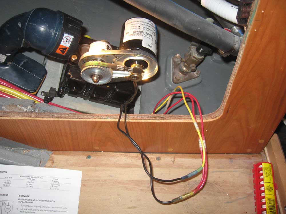
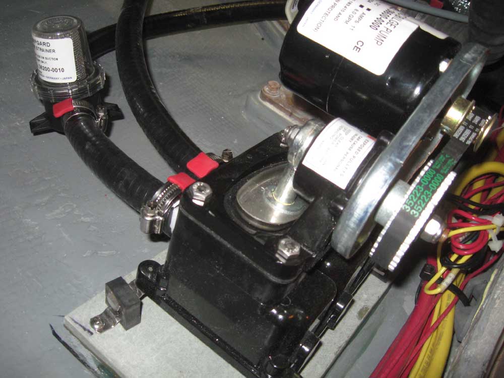
I completed the wiring at the bilge pump itself, making the connections necessary. The pump could run in either direction, though this would affect which hose port was the intake and which was the outlet. The manufacturer had marked the hose outlets, but thoughtlessly chose to supply the pump with a pair of black wires that gave no hint as to polarity. All I could do was make up the connections whichever way and hope that the pump would run the "right" direction according to how the hoses were marked. If it turned out backwards, I could just switch the hoses later. |
 |
|
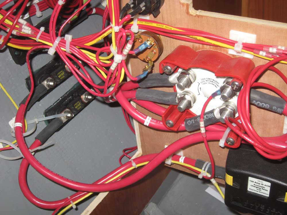
I continued the bilge pump wiring by making up the final connections to the back of the pump switch in the panel, leading the main power supply to the switch directly from the hot side of the battery switch by way of the fuse block and a 15 amp fuse. |
 |
|
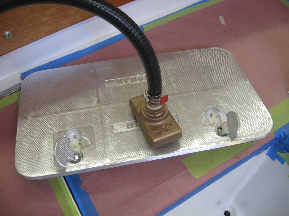
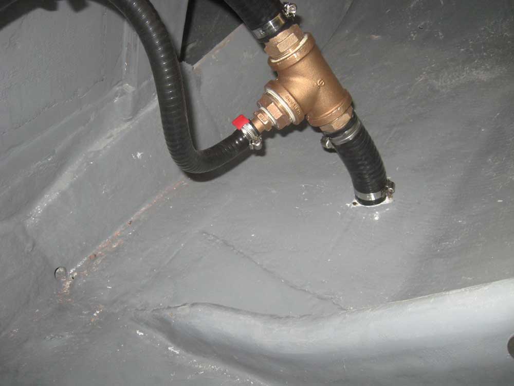
To complete the bilge pump installation, I attached a length of hose to a bronze strainer, which I lowered into the bilge, and secured the intake hose to the pump after passing it through a supplied fine mesh filter. Then, I secured the pump discharge hose, and led it aft to the transom outlet. |
 |
|
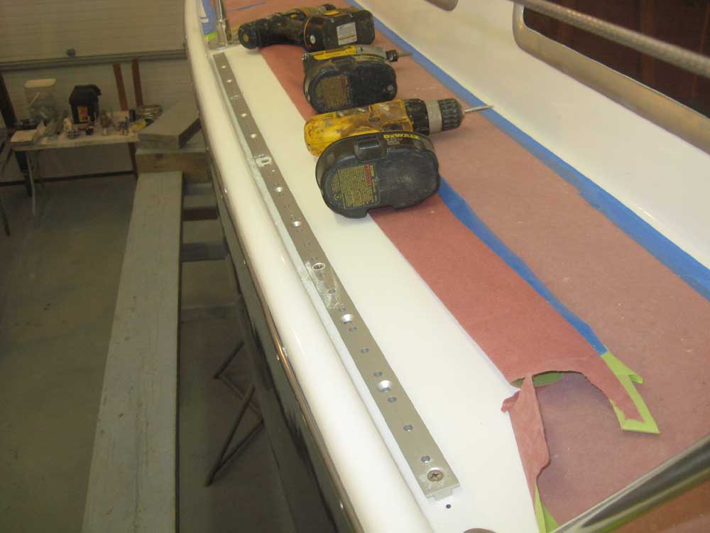
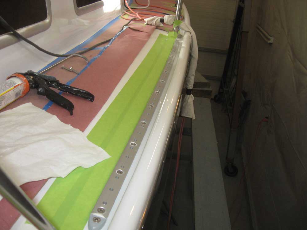
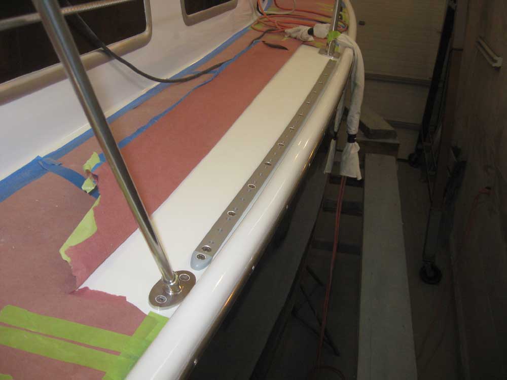
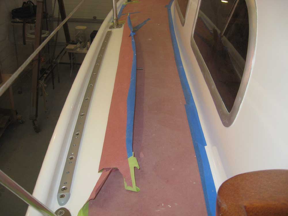
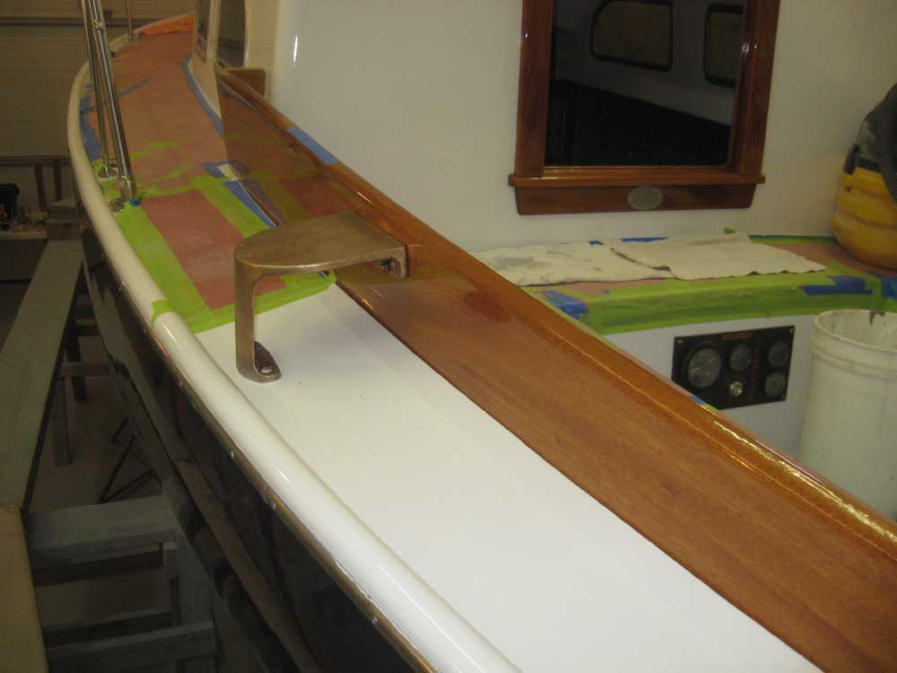
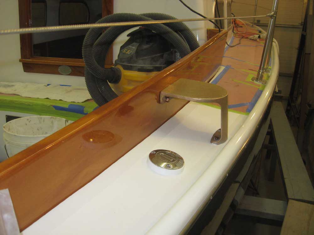
I spent the afternoon on deck hardware. With both the genoa tracks and bronze winch stands in stock, I decided to complete their installations. On each side, I determined the position for the genoa tracks between the aftermost and mid stanchions, leaving room for track ends, and temporarily installed each track, bending it slightly as needed to conform to the shape of the adjacent toerail. Thusly secured, I drilled and tapped all the remaining holes on each side. This far outboard, the tracks were just beyond the end of the deck core, so I was able to press on and complete the installation. |
 |
|
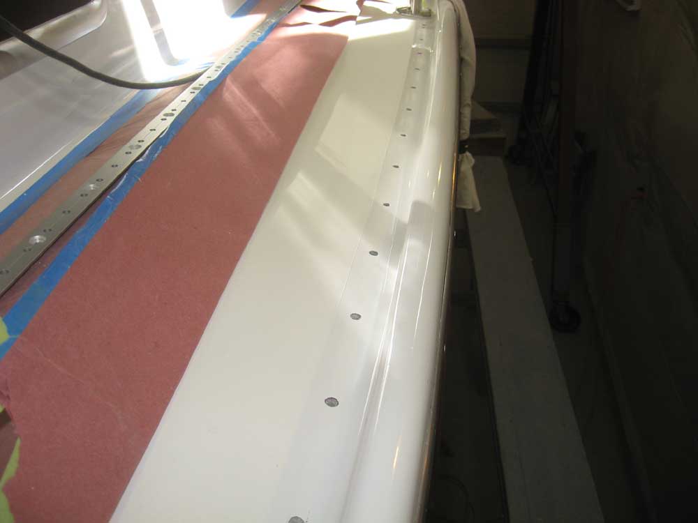
After completing the hole preparation and masking off the nearby deck, I installed each track in a bed of sealant and secured it with screws, after which I headed below and installed fender washers and nuts to complete the installation. |
 |
|
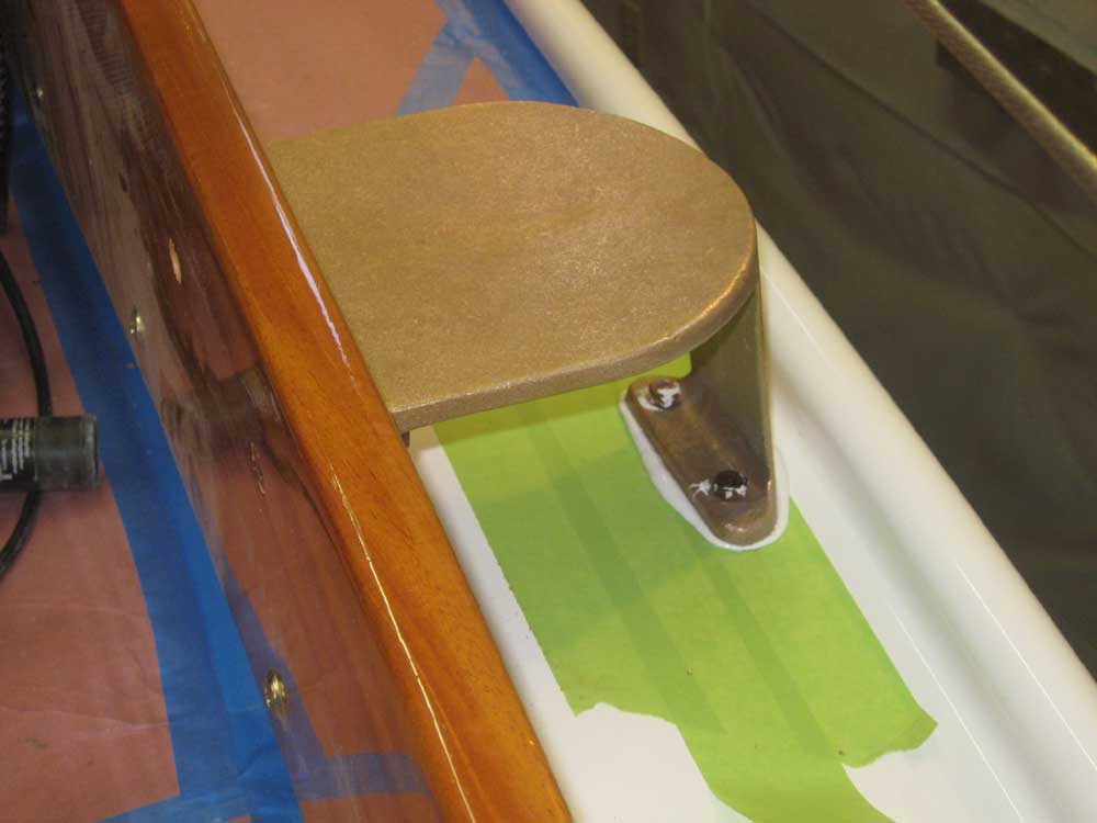
I determined the mounting location for the bronze winch stands, leaving ample room aft of the dodger wings for passage and for winch handle clearance, and installed the stands with bolts through the deck and coamings. The decks in this area were uncored, so again there was no requirement for additional hole preparation. |
 |
|
Finally, I varnished the new interior companionway trim. |
 |
|
|
|