| Circe
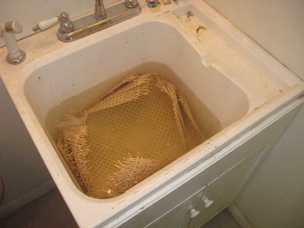
| Saturday, March 6, 2010 In the morning, I installed the prewoven caning material in the cabinet doors. To begin, I cut pieces for each of the 14 doors, each piece somewhat oversize, and then placed the cut pieces in a sink full of warm water to let them soak for a while. During the process, I'd also soak the reed spline used to secure the caning, but this required less soak time. |
|
|
|
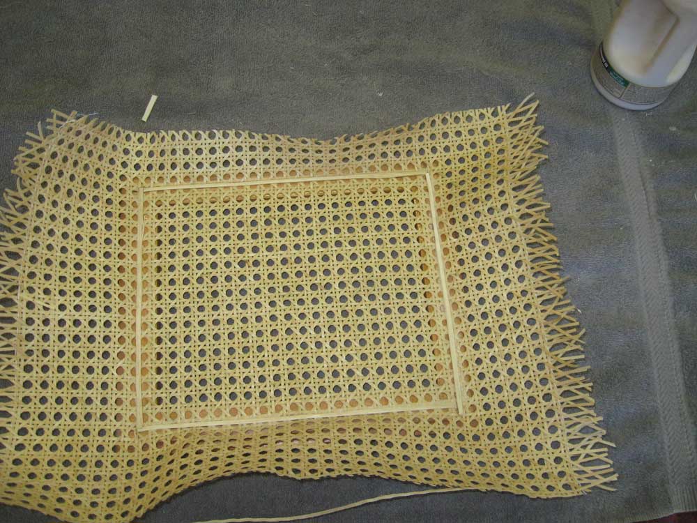
Once the caning had soaked long enough, I installed it in the door frames. I'd previously cut grooves for this purpose, and the doors were already varnished. For each door, I set the caning in place, aligned it, and pressed the caning into the grooves, one edge at a time. I used small hardwood caning wedges for this chore; in the past, I'd found that a small plastic protractor had worked well to roll the material into the groove safely, but I couldn't find one. Once I'd pushed the caning into a groove, I ran a bead of glue and hammered in a length of tapered reed spline to lock the caning in place before moving onto the next side. |
 |
|
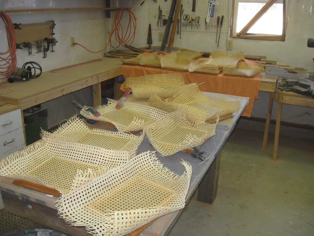
I set the completed doors aside to dry, which would allow the soaked caning material to shrink tightly, and also allow the glue to cure. Later, after dry time, I'd trim off the excess caning and spline edges as needed. It took about 3.5 hours to cane all 14 doors. |
 |
|
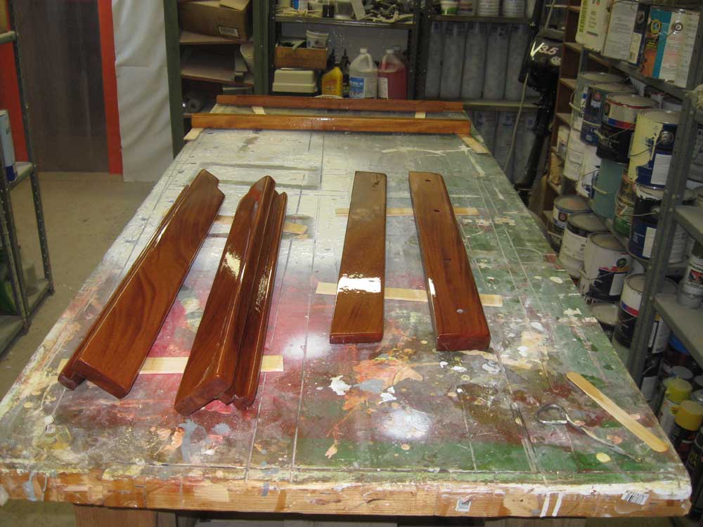
Next, I sanded and revarnished the companionway trim; after a full day's cure time, I planned to install the trim on Monday. |
 |
|
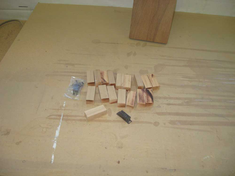
I planned on using small roller door catches for the cabinet doors. Because of the 1/2" thickness of the cabinet face plywood, and the fact that the doors would inset in the opening, I needed to install some blocking to which I could fasten the roller latch assembly. To that end, I cut enough blocks for the job and installed them with glue. |
 |
|
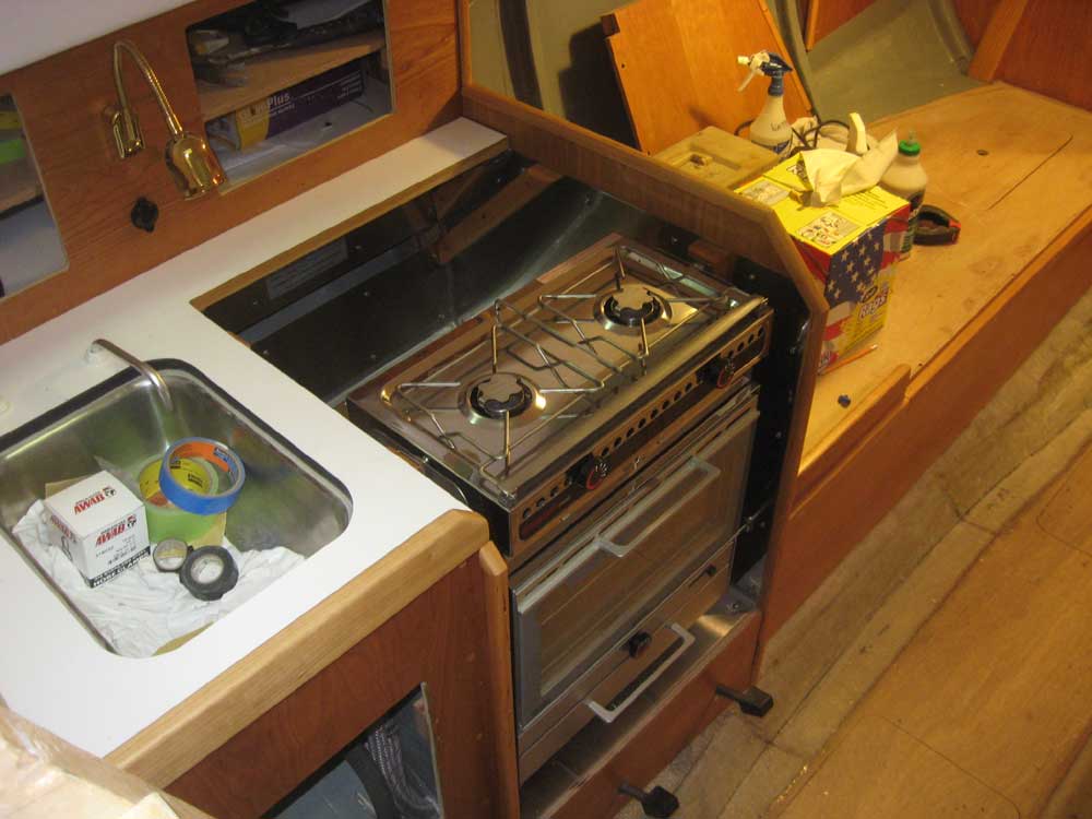
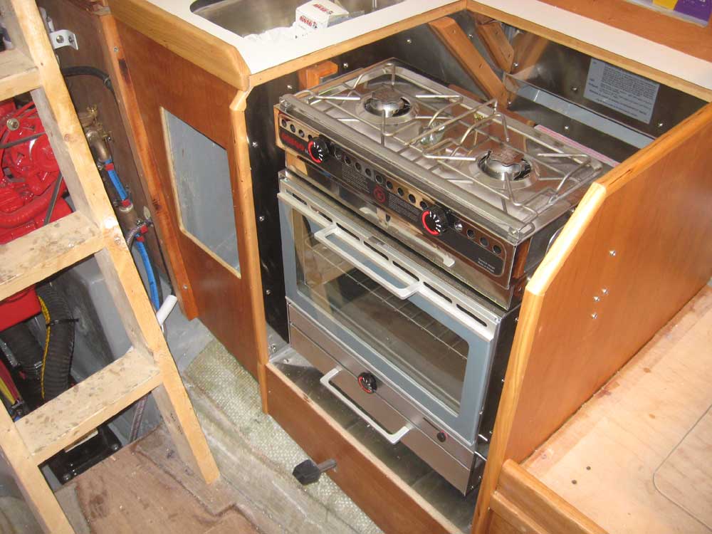
While I was in the cabin, I attended to a few odds and ends of little note, one of which was to install the gimbal lock for the stove; this involved drilling a small hole in the side of the cabinet for the locking pin, located at the bottom of the oven door, and installing a supplied cover plate. I also discovered that I'd arranged the various washers on the stove pivots incorrectly during yesterday's installation, so I corrected that small problem. |
 |
|
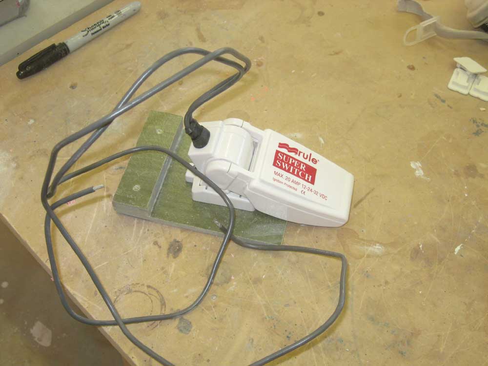
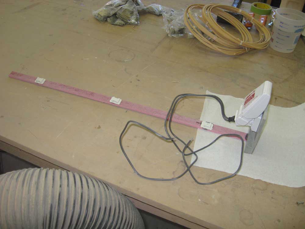
I'd planned on installing the bi-color light and stern light on the pulpits, but discovered that the lights I'd purchased--Aqua Signal--had the wrong bolt pattern on the back, which didn't match up with the holes drilled in the stainless steel pulpit pads. I thought I'd used Aqua Signal lights on similar pulpits in the past, but maybe not. In the event, I ordered Hella Marine lights instead, and postponed the installation till they arrived. The electric bilge pump still needed to be wired, but before I could do that I needed to prepare the float switch for installation. Since the bilge was deep and difficult to access, I couldn't mount the float switch directly to the bilge. Instead, I built a small platform from scraps of prefab fiberglass, to which I attached the float switch with machine screws in tapped holes. |
 |
|
To allow the switch to be placed into--and retrieved from--the bilge, as well as to hold it in place once it was down there, I cut a long, slim fiberglass strip and secured it to the raised back portion of the platform with a machine screw and epoxy. I set this aside to cure for now, but once complete, a single screw at the top of the lifting strip would hold the whole arrangement in place, yet allow for easy servicing. While I was at it, I installed a few wire tie mounts to secure the wires leading down to the float switch. Once the epoxy cured, I could complete the bilge pump/float switch wiring and install the switch in the bilge. |
 |
|
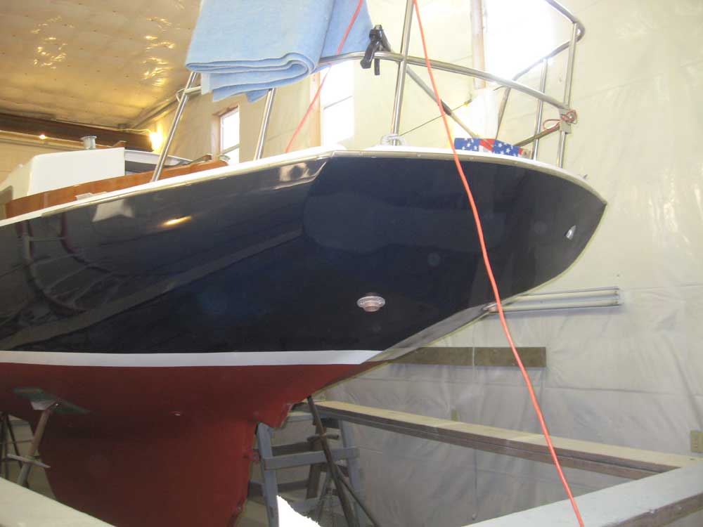
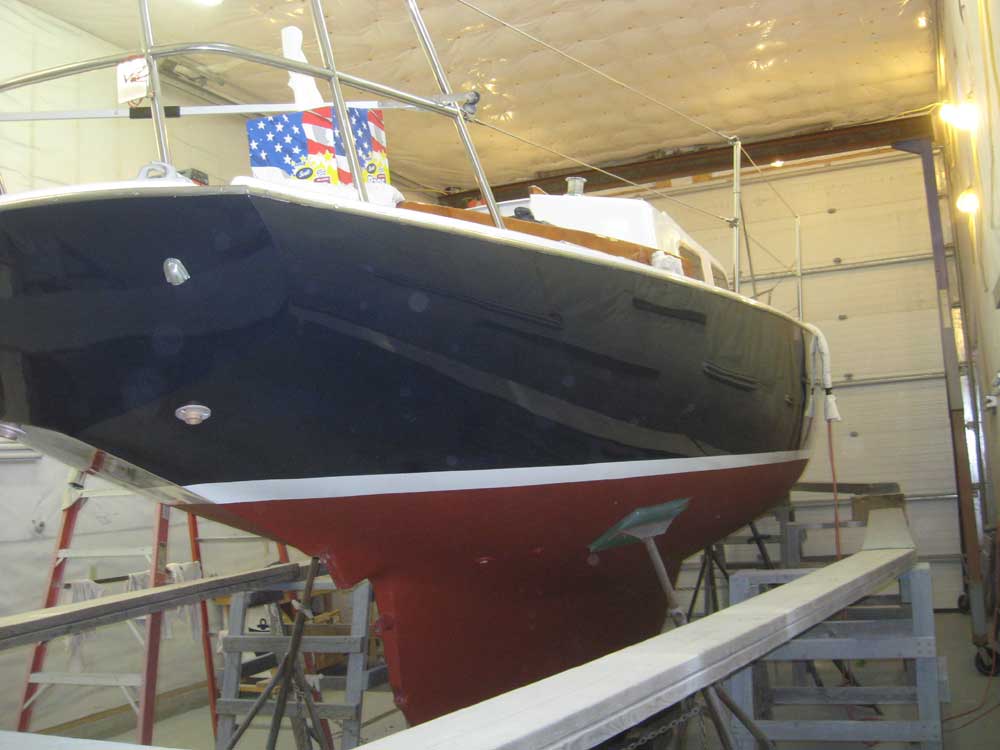
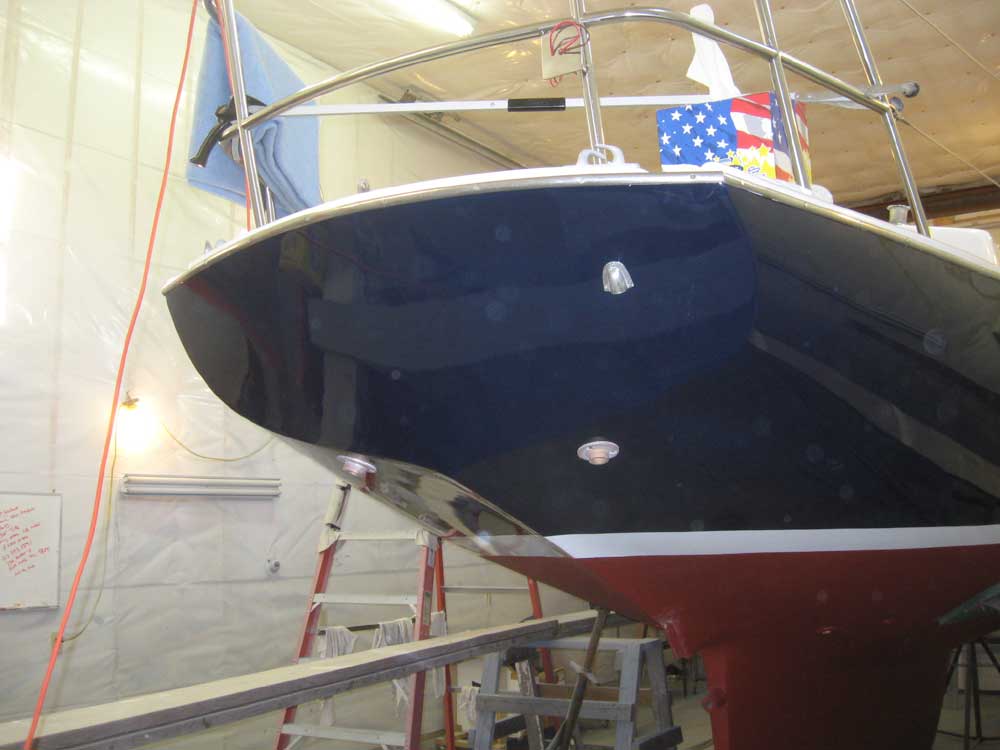
Although at one time a wooden rubrail had been under consideration, we ultimately decided to simply reinstall the original stainless steel rubrail. Now was the time to get this started. I retrieved the rail sections from their outdoor storage area and cleaned them up as needed. I began with the transom section, which featured a compound curve and which, I knew, would more or less only fit in one particular way; this would therefore drive the height and position of the remaining sections, since I'd repaired and filled all the original screw holes during the hull work and had no other specific references. I chose to install the rails with 8-32 x 3/4" stainless steel machine screws in tapped holes, which I thought would hold better than tapping screws. I positioned the transom section accordingly and secured it temporarily with three screws, while I drilled and tapped the remainder; then, I removed it, applied sealant, and resecured it through each hole. In this manner, I worked my way up the starboard side of the hull, drilling, tapping, and securing all three sections of the rail. Working along, I found it was handy to hang the unwieldy sections off the lifelines with lengths of tape, which supported the rails in more or less the correct position till I could get a few screws in to hold them on their own. With the starboard side complete, I installed the short, after section of the port rubrail before it was time to knock off for the day. |
  |
|
|
|