| Circe
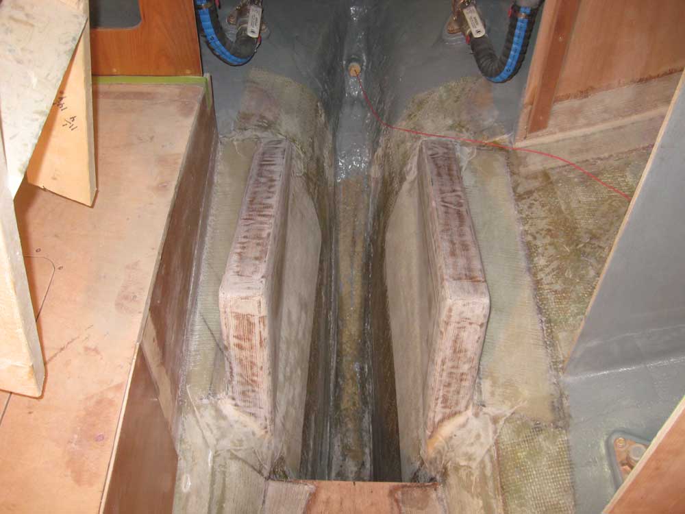
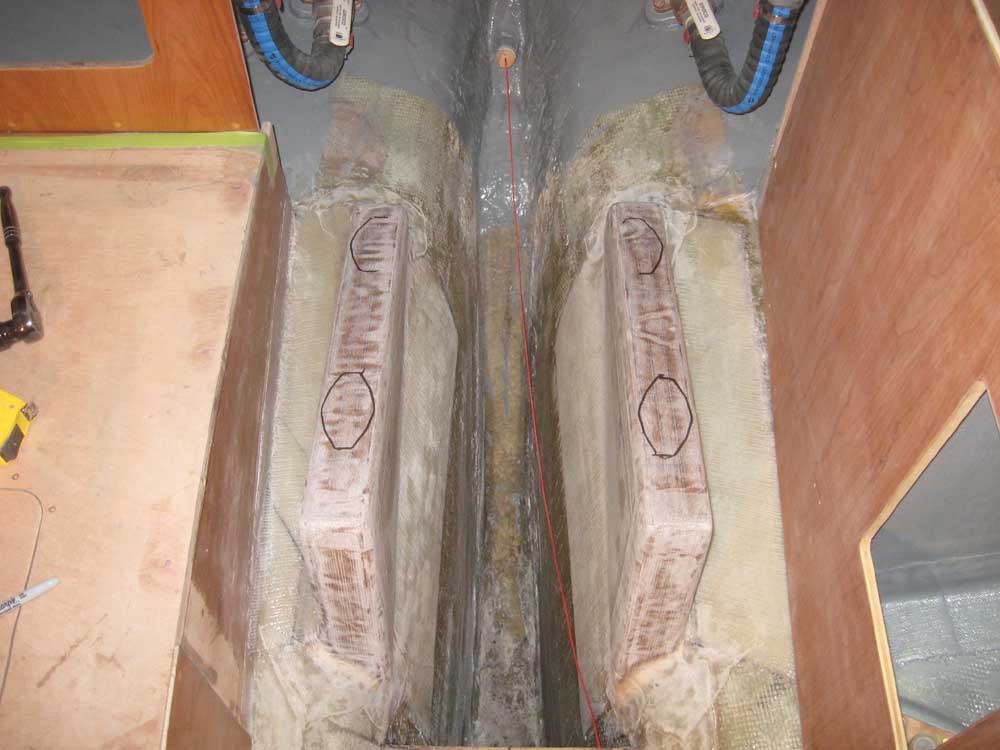
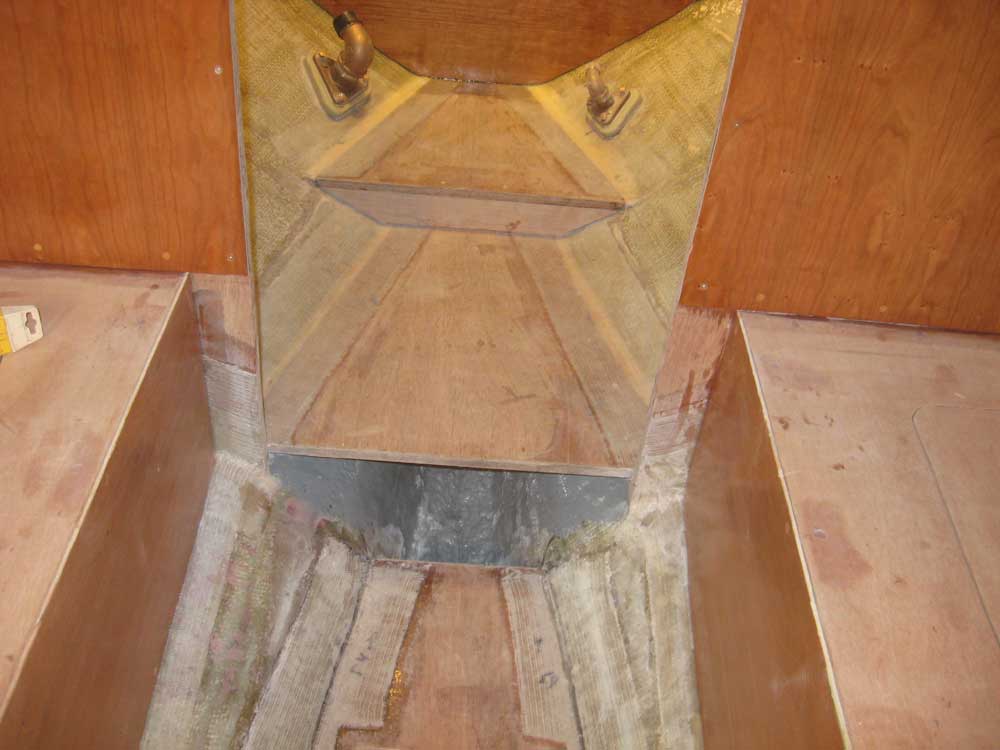
| Tuesday, December 8, 2009 Once more, the engine foundations received the first attention of the day. I washed and sanded yesterday's fiberglass sheathing, and cleaned up the area. |
|
|
|
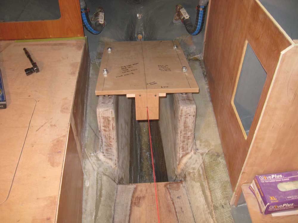
Next, I set up the alignment string and engine template again in order to make the final determinations for the engine's longitudinal (fore and aft) location on the new foundations. During the foundation construction, I'd more or less determined this position, but now needed to lay it out accurately so I could proceed with the next steps of engine installation. I aligned the template carefully according to the string, and according to a reference mark I'd made demarking the forward end of the engine, and after checking the fit from all angles, made some marks on the foundation to register the mounts' locations. |
  |
|
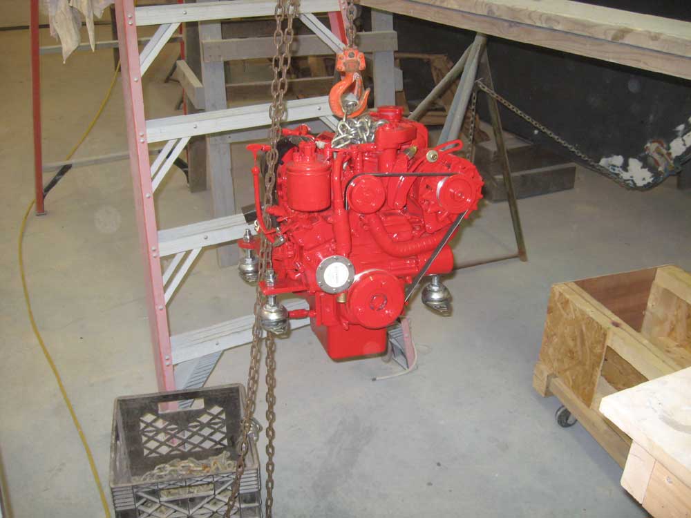
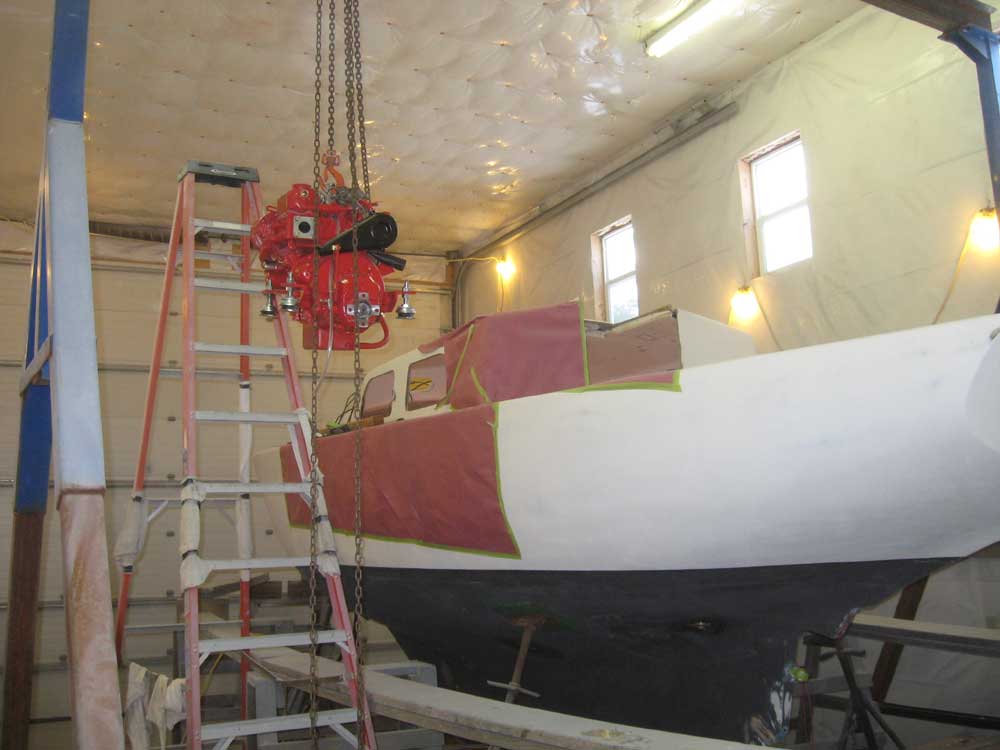
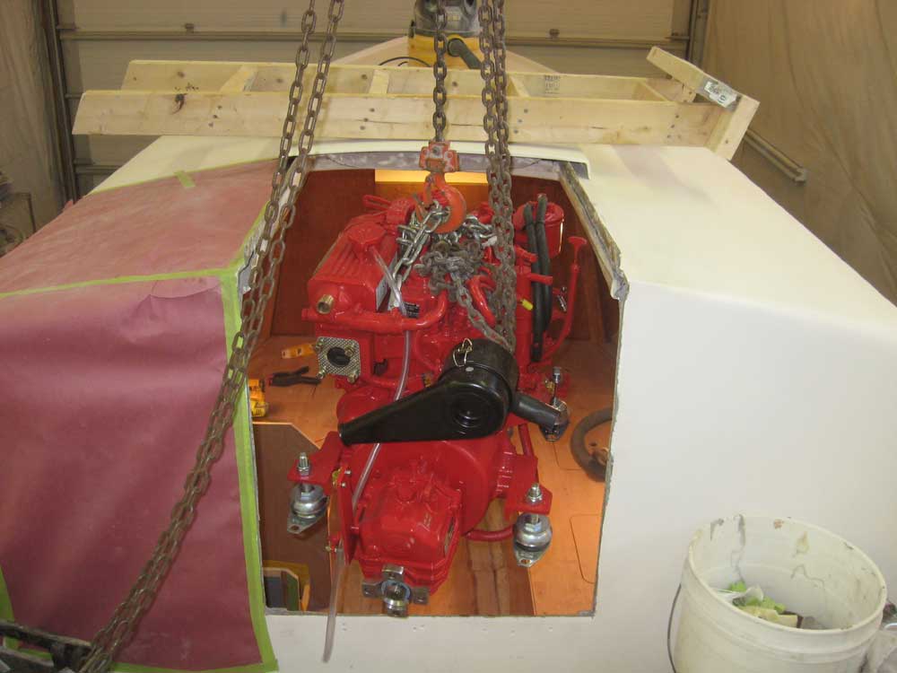
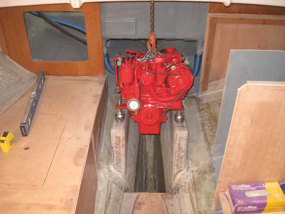
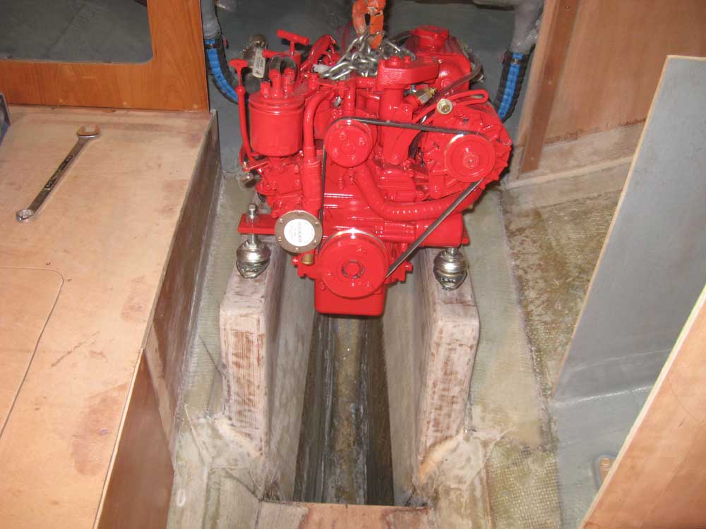
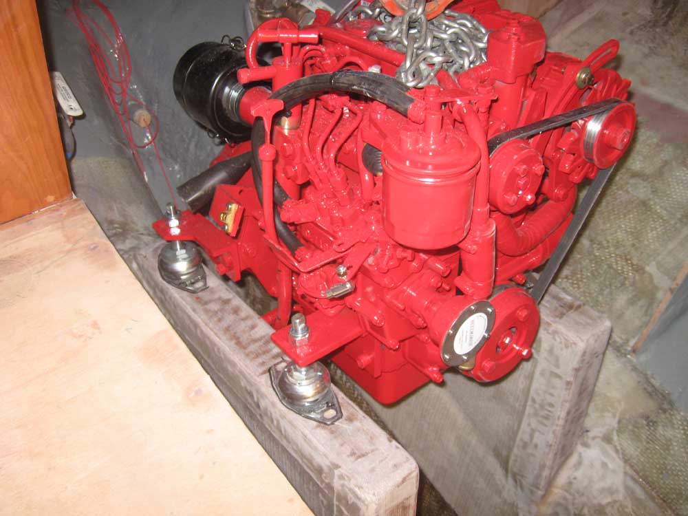
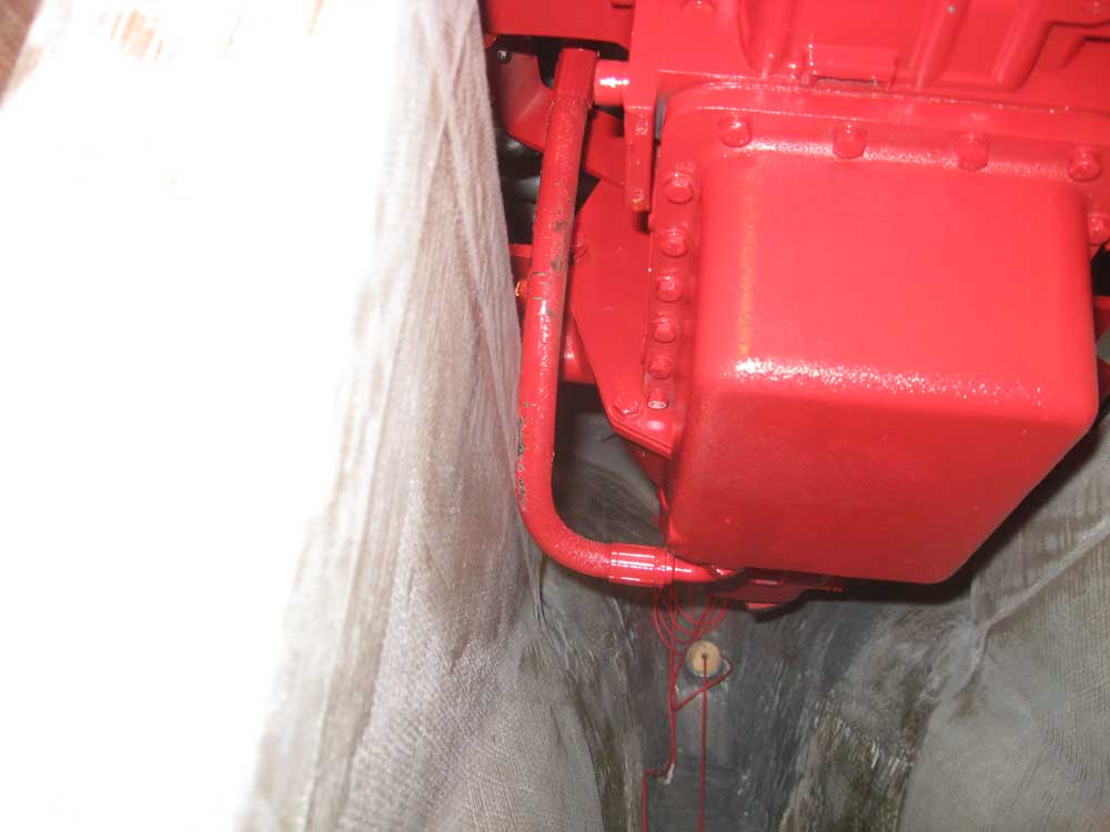
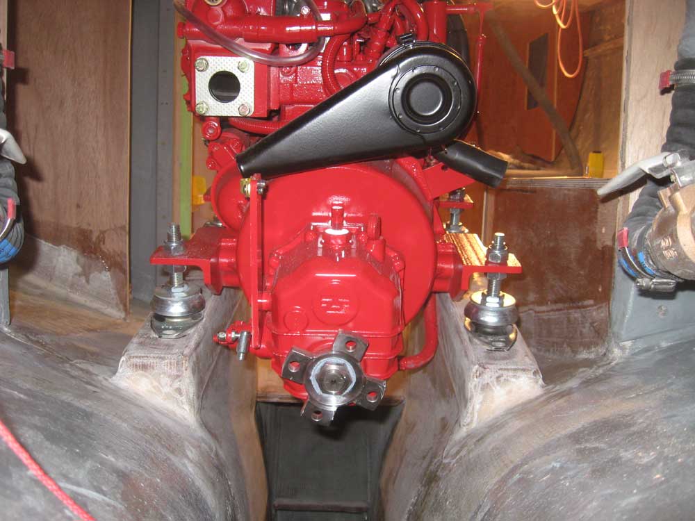
Since additional cabinetry and other installations would depend on the engine's location, I wanted to be sure it was right. I needed to paint the engine room before I permanently installed the engine, but that would have to wait a couple weeks for the fresh epoxy to cure, else the paint might not cure properly over the new material. However, I decided it was worth it to lift the engine temporarily into the boat to double-check its fit in the proposed location and ensure that there would be good access to all parts of the engine for installation and maintenance. I removed the engine from its shipping crate and installed the flexible mounts, then lifted it into the boat and onto the engine foundations. I found that a hose leading from the oil sump to a manual oil change pump rubbed tightly against the starboard foundation, but I could realign the hose and eliminate this problem before final installation. Otherwise, the engine sat perfectly on the marks I'd made from the template, and its position looked good: far enough aft to avoid too much protrusion into the cabin, yet far enough forward to ensure excellent maintenance access. |
  |
|
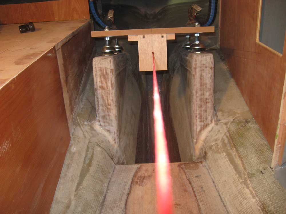
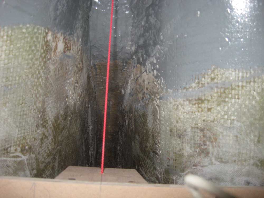
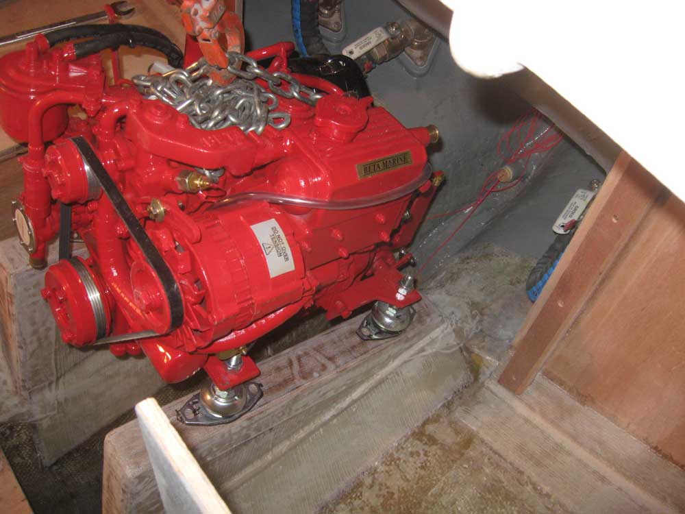
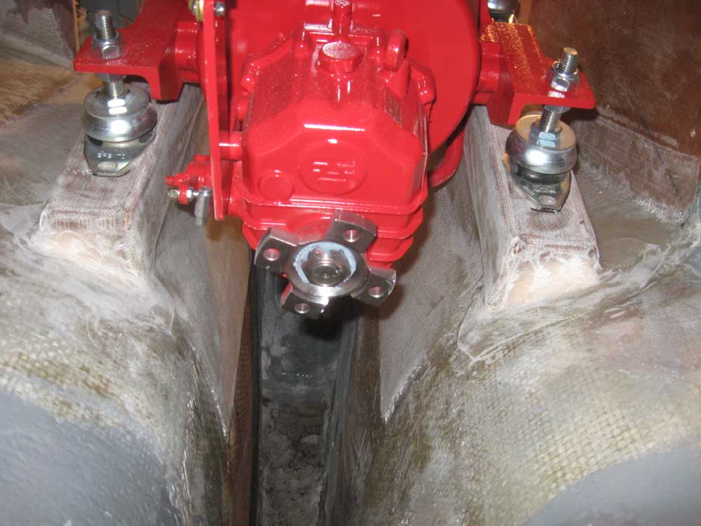
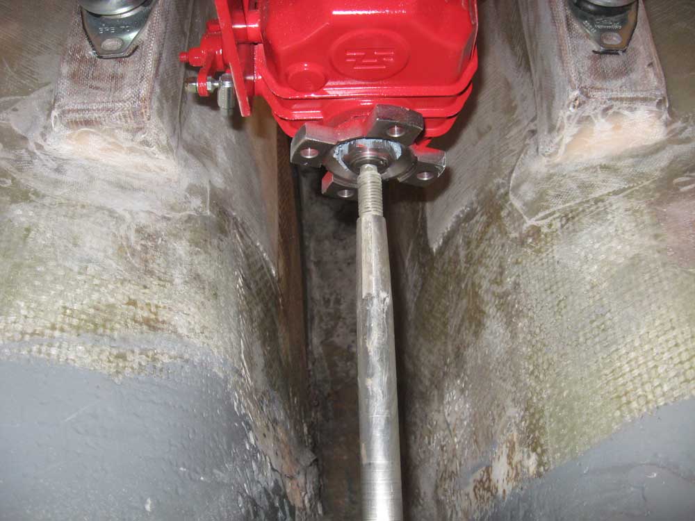
There was room for adjustment on the engine mounts, as designed, but I thought I'd take a spare shaft and run it through the stern tube to check the basic engine alignment in real-world terms, though the center of the transmission coupling appeared to be right in line with the stern tube when viewed from outside. With the mounts more or less adjusted as they had been when I used them on the template, but with minor adjustments to accommodate flat and lockwashers beneath the engine flanges, I was pleased to see that the shaft lined up very well with the center of the coupling. Yes, I know that this is the wrong end of the shaft; the other end of this old shaft has a coupling attached, so I inserted it backwards for this visual test. |

 |
|
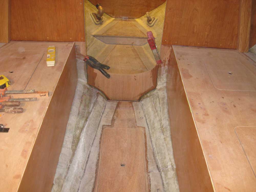
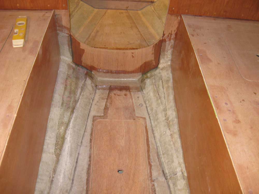
Pleased with the engine's location, I traced around the mounts and their bolt holes with a marker, and removed the engine back to the floor for storage until I was ready to install it permanently, within a couple weeks. Now that I was done with the engine alignment string, I prepared to install the vertical oak mast compression posts at the forward bulkhead. However, I quickly realized another omission that I needed to take care of before I could install the posts: filling in the lower section between the bulkheads, to cover the gap between the head sole and the main cabin sole. This would also incorporate additional 1/4" cherry veneer to cover the areas that would be directly behind the posts, which I'd not included in the main veneer process. I measured, scribed, and cut a section of 18mm plywood to fit the opening and fit against the hull beneath, and struck a curve on its top edge to provide a lip above the head platform and offer a traditional appearance to the door opening. With the base plywood shape determined, I traced it onto 1/4" cherry plywood and cut the veneer piece that I'd install shortly. Once the fit was sufficient, installed the small section in epoxy adhesive; late in the day, when the adhesive had cured sufficiently, I applied 4" tabbing to the lower edges of the little center section to secure it. |
 |
|
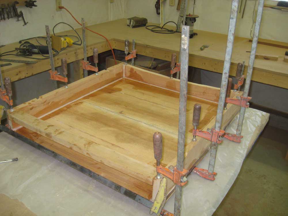
I continued work on the sea hood. Yesterday's subassemblies were cured enough to continue work, so I unclamped them and cleaned up excess epoxy from the glue joints. Then, I secured the top to the remaining framework with epoxy and clamps, again forming fillets on the inside corners to strengthen the joint. I left the top oversized for later flush trimming. |
 |
|
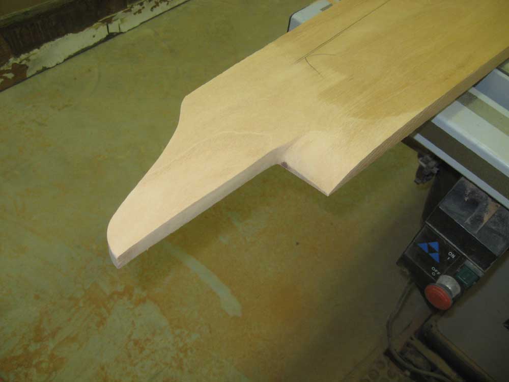
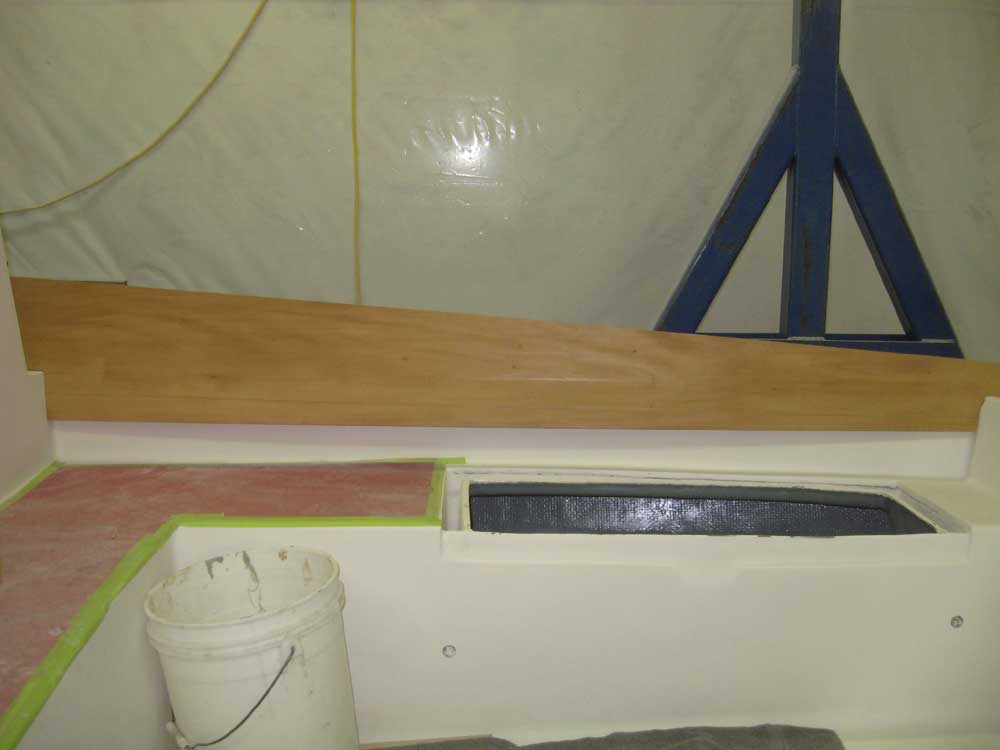
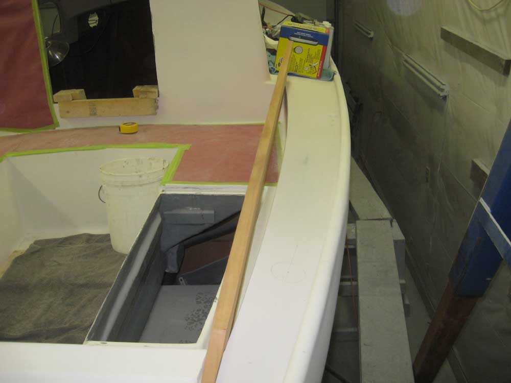
The coamings required shaping and fitting before they could be dry-installed. Using the old coamings as a rough guide, I removed some of the material from the hidden portions of the coamings that would fit into the cockpit corners, and also shape the aft end so it would fit next to the raised molding at the end of the cockpit, since the new coamings were thicker than the old. Eventually, I was able to put the starboard coaming in place, though I'd need to press it into position to make the bend, for which I'd need to rework an old jig that I'd made long ago. Meanwhile, I worked on the shaping of the port coaming. |
 |
|
|
|