| Circe
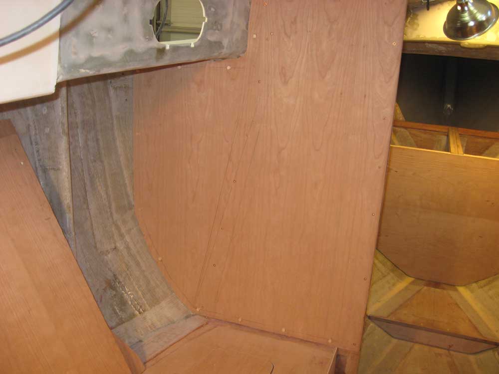
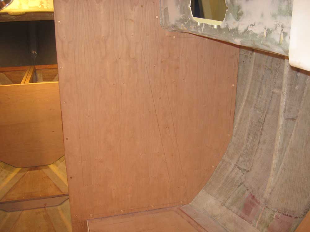
| Wednesday, November 18, 2009 First thing, I removed the temporary screws from the main bulkhead panels, and bored the holes for cherry bungs, which I installed. |
 |
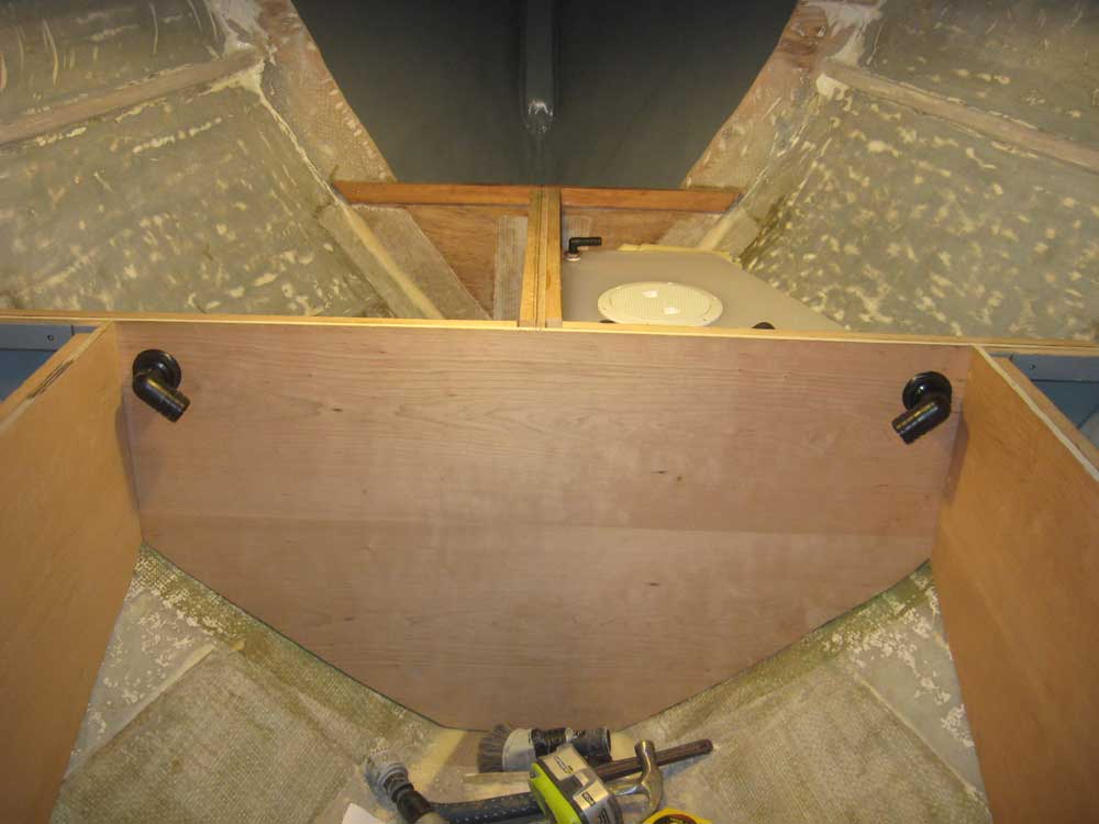
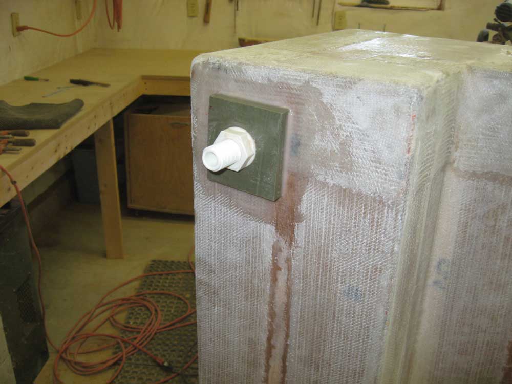
| It was time to permanently install the new tankage--waste and water. Everything I needed was in stock and ready to go. Well, everything except one bushing that I needed, but I could continue without that. To begin, I removed both tanks from their lockers and installed the required hose nipples: the tanks came with threaded inserts, allowing me to choose the end fittings. I installed 1-1/2" 90° nipples for the waste inlet and pumpout, as well as for the water tank fill, plus a 5/8" 90° nipple for the waste vent and a 1/2" nipple for the water pickup. I left the water vent alone for now as I needed an additional fitting. I wanted to ensure that everything I wanted (and needed) to do with the head plumbing, pump, and related installations would work once the tanks were in place, and this meant that I had to actually conceive what I was planning to do, how I was going to run hoses, where I'd locate the head pump, and other decisions. Every decision might affect the next one, so I tried to think of everything before I filled up the spaces around the tanks with foam. At length, and having consulted the head documentation, mocked up the toilet and pump, and considered the options, I installed two 90° through-bulkhead connector fittings for the eventual sanitation hoses. For appearance and to minimize clutter and interference, I chose to install one fitting on each upper corner of the cabinet forward of the head. The hoses were a fact of life and couldn't be eliminated, so I hoped this would be the best means of avoiding as much eyesore as possible while also making the system workable--not only from the installation standpoint, but also going forward. Other installations could come later, but once I'd determined these locations, I could proceed with the final tank installation. I removed the through-bulkhead fittings for now, so that I could varnish the area without impediment. I covered the insides of the holes with tape to protect against later steps. |
|
|
|
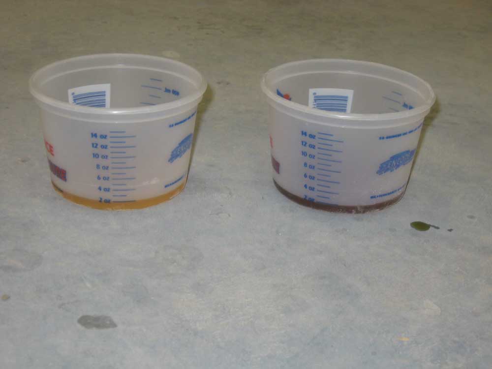
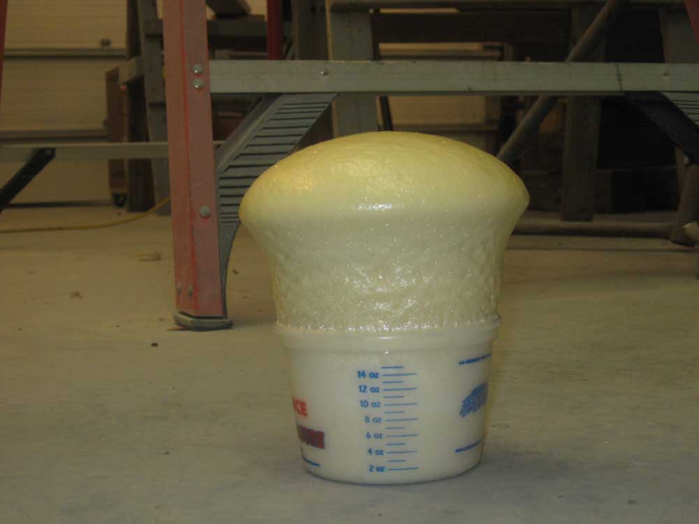
To secure the tanks and fill in remaining gaps around the foam scraps, I chose 2-part expanding foam. I'd not used this stuff in years, so before beginning the actual project I mixed a small test sample to gauge the foam's expansion ratio, speed of expansion, and other factors. I mixed 2 oz. of each component and waited for the fun. Expansion looked to be about 8:1, and was very controlled and relatively slow-acting, meaning I'd have plenty of time to mix the components and pour the liquid where it needed to go. |
 |
|
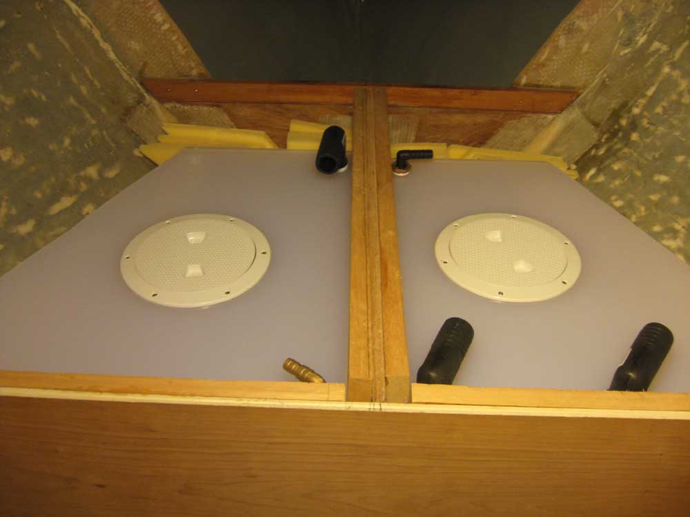
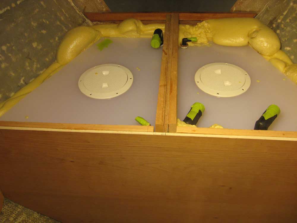
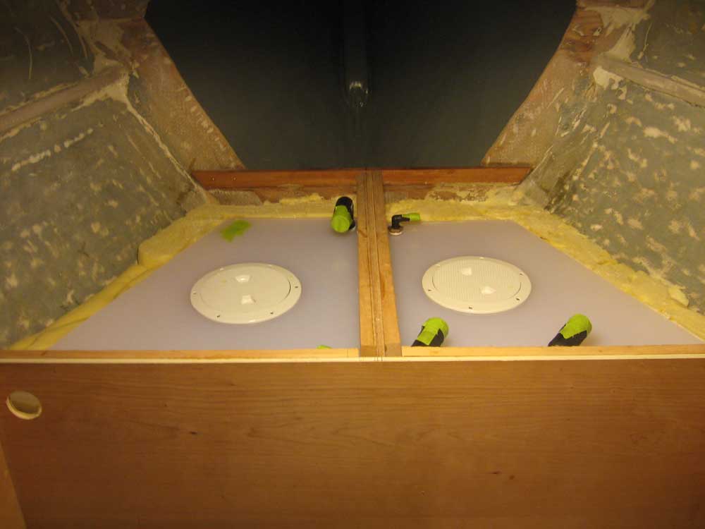
In relatively small batches, I filled the areas around both tanks with the foam. I used a bit more than I needed to on the starboard side, so used less to port, giving me less excess foam to remove afterwards. The foam held the tanks securely in place, but later I'd add some braces across the top to hold them down as well. When the foam cured, I used a saw and chisel to remove the excess above the tanks, and cleaned up from the operation. |
 |
|
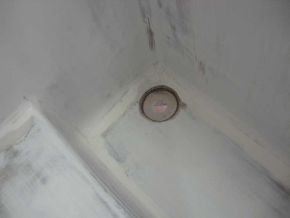
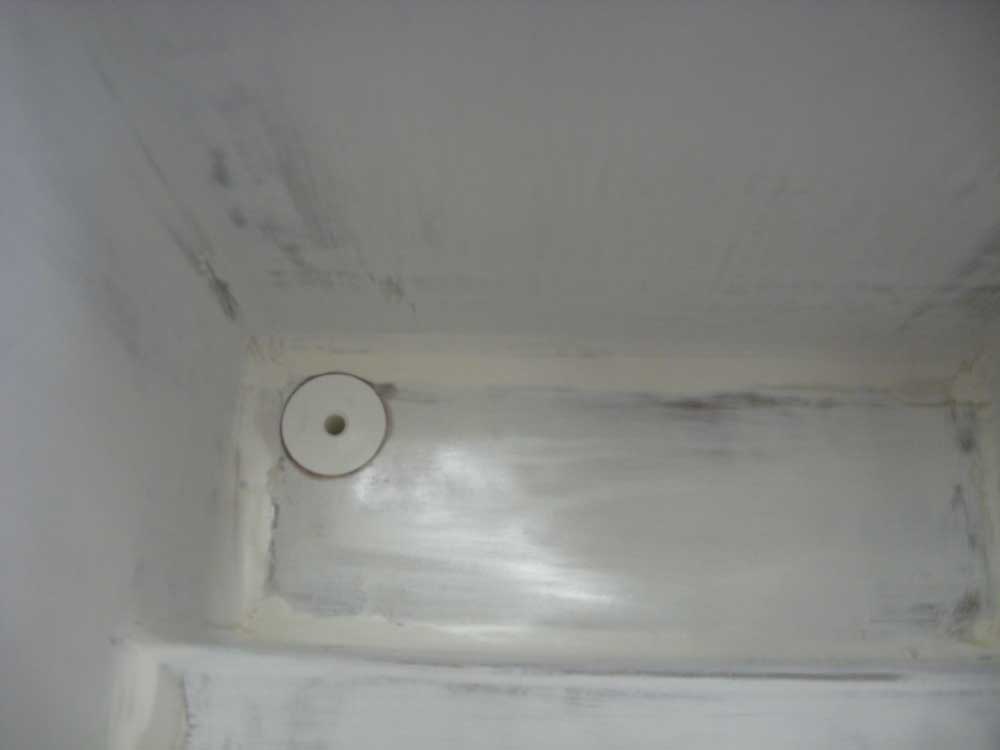
I lightly sanded the primer coat inside the icebox, and then prepared to install the drain fitting. Using a large Forstner bit, I drilled a hole that was slightly smaller than the overall diameter of the beveled, flush drain fitting, and then used a small drum sander to bevel the edges of the hole so the fitting could slip in. The depth of the hole was such that it left the fiberglass on the outside of the icebox intact, but to reinforce the area I prepared a square of 1/2" prefabricated fiberglass as a backing plate. Then, I installed the drain fitting in thickened epoxy, securing the backing plate with additional epoxy and the drain fitting's own nut. |
 |
|
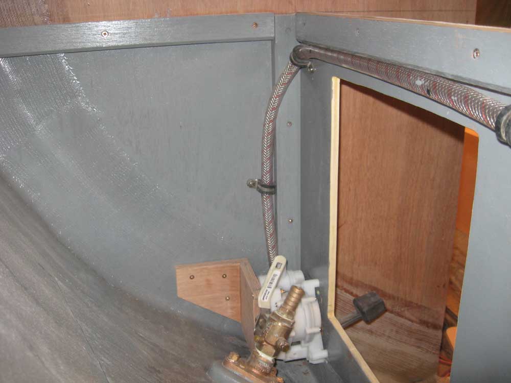
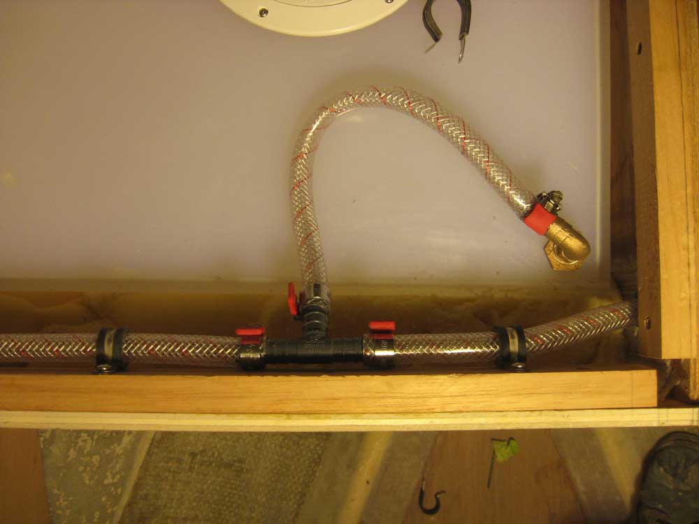
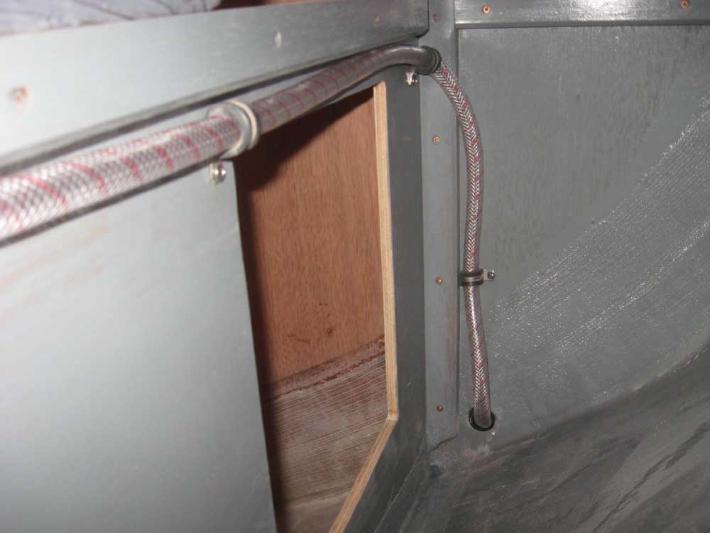
With access as good as it would ever be, it seemed a good time to install the potable water hoses. During what remained of the afternoon, I drilled holes through bulkheads, installed short sections of hose as chafe protectors, and ran and secured the 1/2" water hose to the head sink pump and aft through the lockers to where the galley sink pump would go. Note that the barbed fittings shown feature dual barbs for 1/2" and 5/8" ID hose, so the hoses, being 1/2", only push on to the extent shown by design. |
 |
|
|
|