| Circe
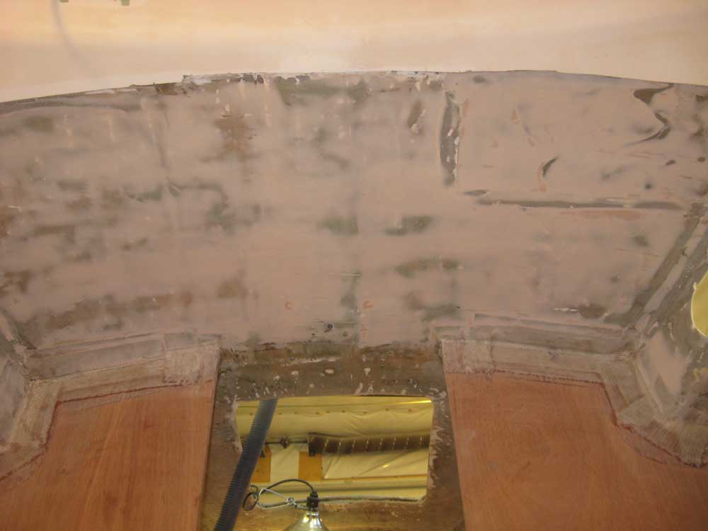
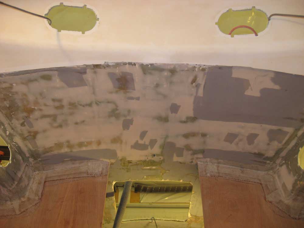
| Monday, November 9, 2009 It was one of those days where things seemed to take longer than expected. I began by sanding the fairing compound I'd applied to the overhead on Friday. This took longer, and was more difficult, than I anticipated; the that which-shall-not-be named tan stuff I was trying to use up on simple jobs was making the jobs more difficult, so I threw out the containers so I'd not be tempted to use it ever again. After sanding the thin, yet rock-hard and unyielding filler successfully, I cleaned up the mess. There were a few minor low spots that I'd refill (with a different material) later in the day. While I was in sanding mode, I washed and sanded the inside of the icebox one final time to prepare it for the paint room. |
|
|
|
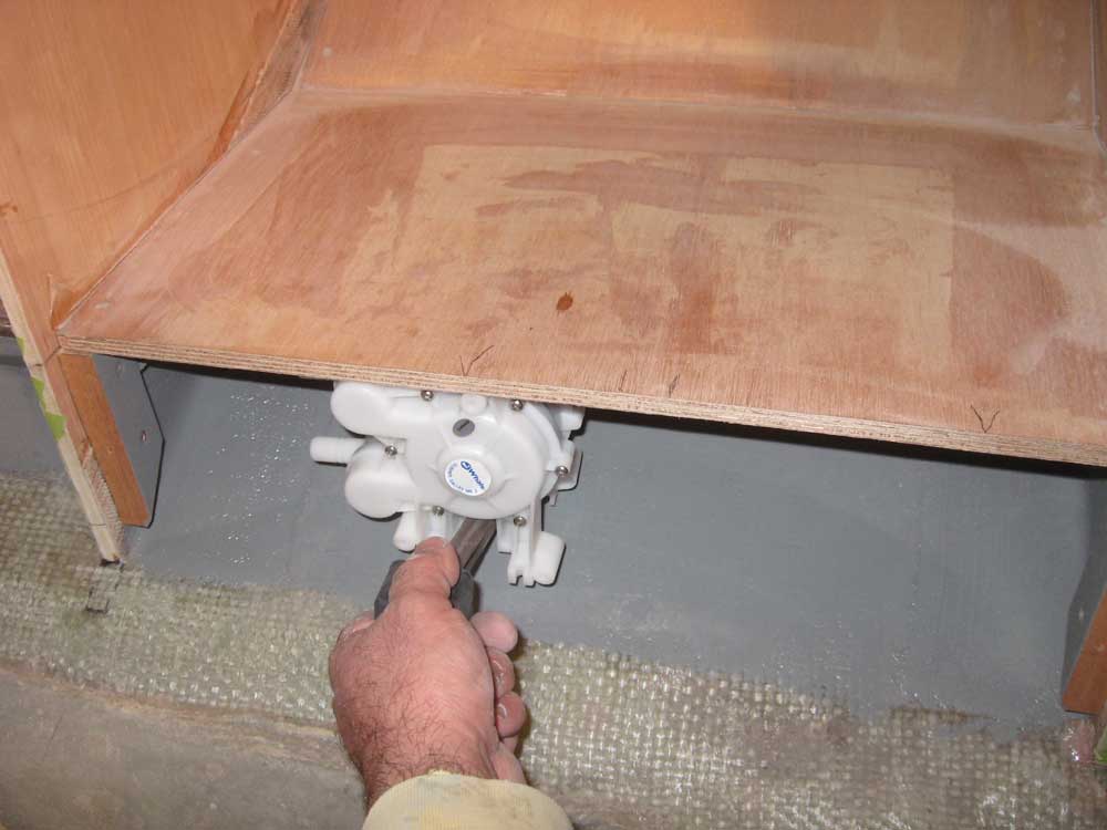
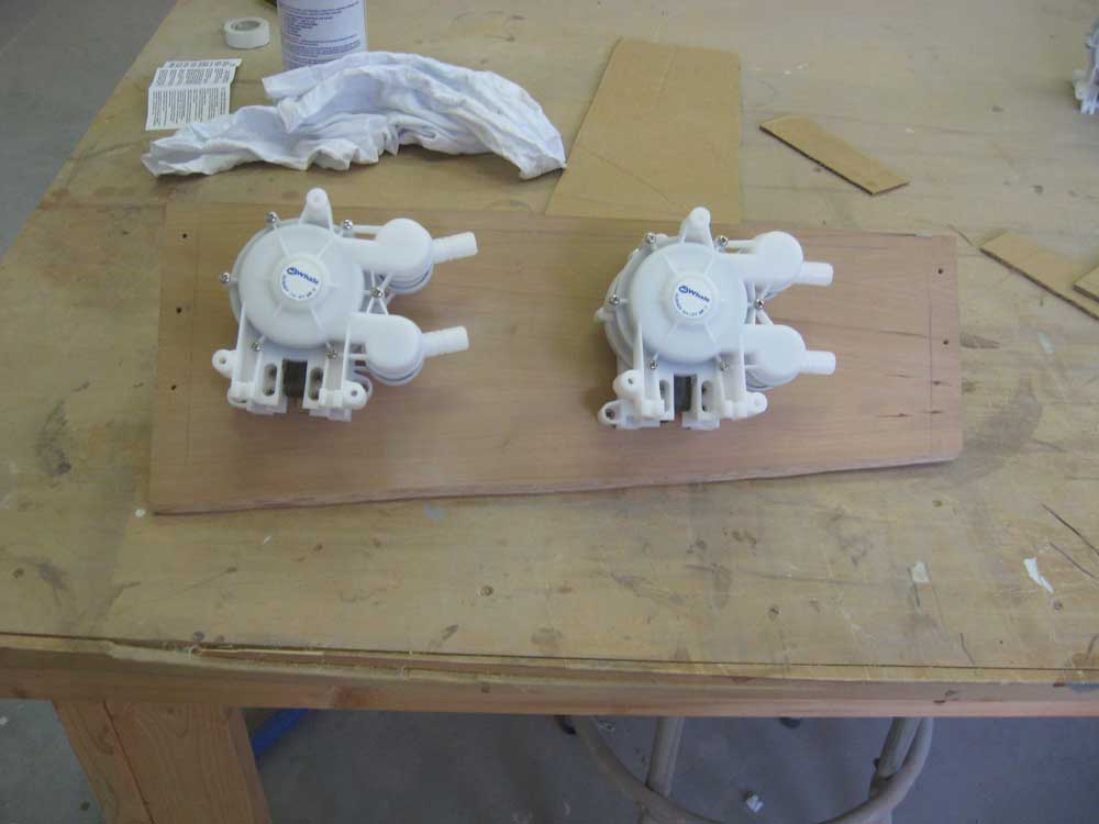
For some reason, I decided that it was time to fit the fresh water foot pumps--perhaps because the water system was on my mind with the tanks due later this week, or because I wanted to get the pump slots cut before I went too far with any additional cabinetry work. In any event, I'd determined somewhat earlier, with reasonable surety, that the foot pumps would fit in the space beneath the stove. Now it was time to find out if I'd been right. If not, I'd need to figure out where else to mount the pumps. (I hoped they fit.) With the front panel removed, I tested the pumps' fit in the open space beneath the bottom of the stove. Allowing plenty of room for the eventual hose connections, I determined the general locations of the two pumps (one fresh, one salt), and was pleased to find that both fit without trouble--that is, without interfering with the curvature of the hull. |
 |
|
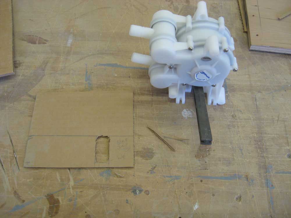
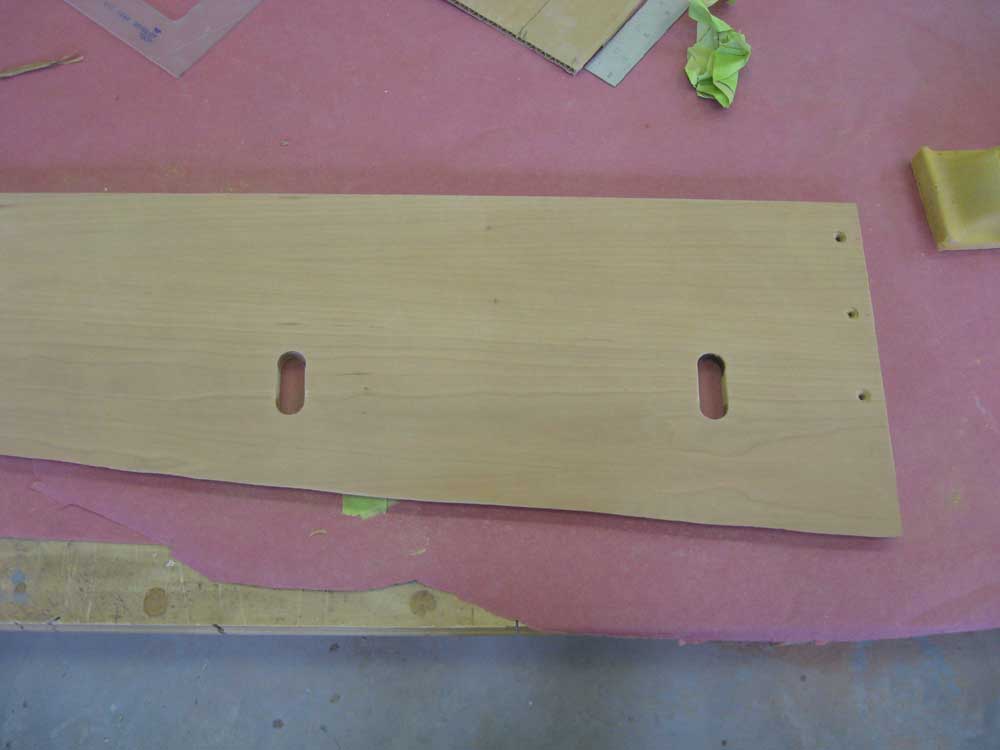
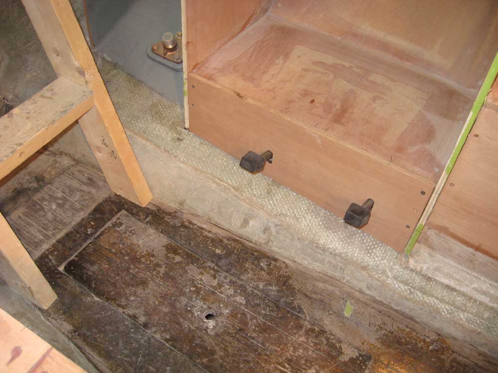
With the locations thusly determined and duly marked, I transferred the marks to the front panel and prepared to lay out and install (at least temporarily) the pumps. These foot pumps are great--effective, simple, and durable--but their installation in tight spaces is complicated by the fact that the foot lever is permanently mounted, meaning that one cannot hold the pump in position to mark screw holes. Therefore, the slot for the foot lever must be cut first. Since the slots required are not something one wishes to err upon, this means that additional thought and layout are required before making the cuts, to ensure that they are in the correct position. To that end, I made a simple cardboard template that I could use to determine the overall position of the pump, and therefore the slots, with some accuracy. Clearances in the chosen space were tight enough that I didn't have much room for error, the way there might be in other installations. The template also allowed me to play with the pump lever slots in order to get them the correct length--that is, as small as possible without impeding the pump operation. With a template cut out, I made reference marks on the front of the panel, checked the measurements, and then bored 5/8" holes at the top and bottom of each slot location, after which I connected the holes with a saw. Then, I could insert the pump levers and secure the pumps to the back of the panels with three screws each, as required. The panel, which would be removable for service, fit fine with the pumps installed, and the foot pedals' location would be convenient given the location of the sink. Later, I might cut the levers down a bit so the pedals don't protrude so much into the passageway, but I'd leave that decision for another time. |
  |
|
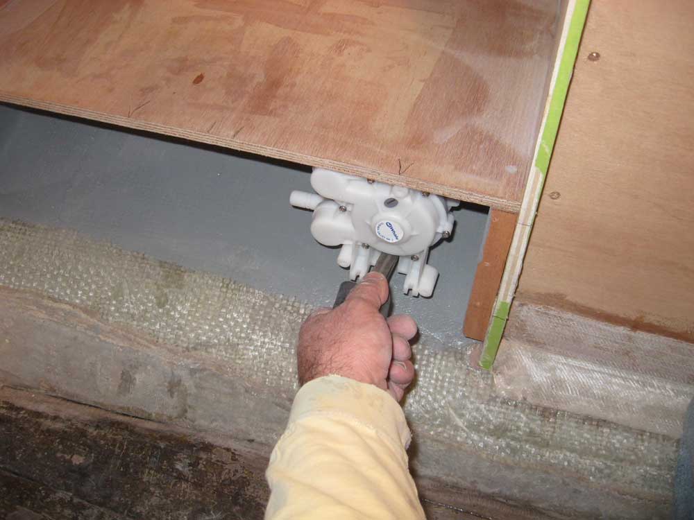
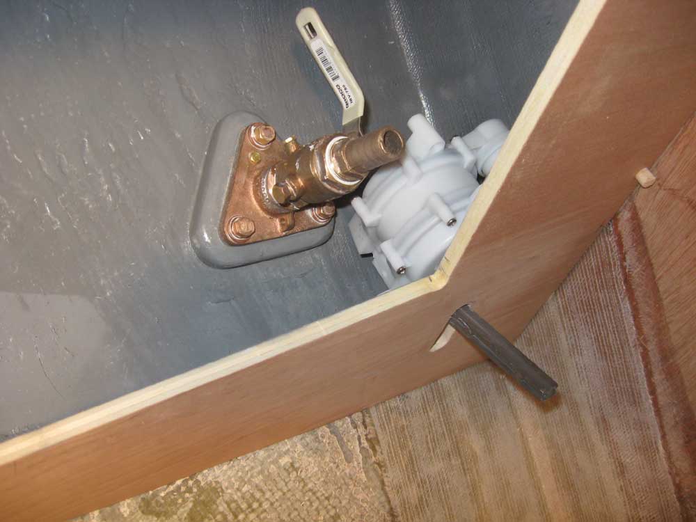
I also had to install the foot pump for the head sink. Again, like with the vanity locker doors, I wish I'd thought of this before I'd installed the vanities, as the job would have been easier. One cannot always think of everything in the absolutely perfect timeframe all the time, unfortunately. The pump really had to go in the lower right (aft) corner of the cabinet, out of the way and as close to the sole as possible. Clearances here ended up being tighter than I'd have ideally hoped, with conflicts arising from the angle of the hull and the placement of the sink drain seacock. Nonetheless, there was enough room for the pump. Using my handy template, I determined the location of the pump inside and out, and after a few adjustments made the cuts for the lever slot, following the process I used on the galley pumps. I ran into trouble when I found that in this location, I couldn't access two of the three screw holes adequately. With difficulty, I did get one of the two problem screws installed, but the third one--the lowest one--was simply too crammed into the tight angle formed by the bulkhead against the hull. Eventually, I had no choice but to move the pump up slightly by extending the lever slot. This was better, but it was still tough access, and the prospects of reaching the third, lowest screw--now or in the future--were minimal. I decided to build a sort of bracket that would hold the pump securely on that side by fastening it to the main bulkhead behind, rather than in the tight corner, but that would be a project for tomorrow. In an effort to keep the head sink drain from dominating the cabinet opening, I'd located its seacock more to the aft side, rather than directly beneath the sink. This ended up forcing a tight clearance between the valve and the potable water pump, but there was adequate clearance to allow easy operation of the seacock valve in any event. I was glad that at least I'd thought to install this pump before the vanity countertop was permanently installed. |
 |
|
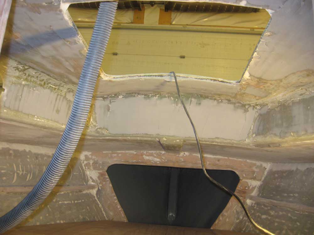
To wrap up the day, I solvent-washed the overhead and applied a second coat of filler to the areas that required it. I also installed a skim coat of filler over portions of the head overhead and cabin trunk in order to similarly smooth these areas in preparation for paint. |
 |
|
|
|