(page 2 of 2)

Miss Helen 10

I continued the varnish work on the new window trim with a quick sanding and third coat.

During the remainder of the day, I finished up the masking for the brightwork maintenance on deck, this time focused on the interior of the poop deck, cockpit, and coachroof, along with above the port eyebrow trim.

Miss Helen 9

I lightly sanded the new epoxy filling the old deadlight screw holes to flatten it and remove any hard spots.

While I had the trim down, and since I’d already drilled small pilot holes at each screw location, I took a moment to drill 3/8″ diameter recesses to accept bungs later.  I did this on the drill press to ensure accuracy and consistent depth.

Now I test-fit the trim again.  I would have liked to drill and tap for some of the screws to help me hold it, but the fresh epoxy would hold threads better if I gave it come cure time, so for now I relied on clamps.  I arranged the trim so it fit in all the corners, and clamped it in place.  But checking the reveal inside, I noticed that the lower forward corner was too low, the result of the bottom trim piece being slightly too long.  This wasn’t a surprise, since I’d suspected all along that the broken-and-repaired old trim that I’d used as a pattern had “grown” a bit in the process, making it slightly longer than original and therefore skewing the forward joint.

I needed to adjust the joint between the forward end of this lower piece and the forward vertical piece, so from outside I adjusted the lower trim till it was at the correct height, then overlapped the two pieces to make some reference marks for a cut.  I started by taking a small amount off each piece of trim, as both required minor shortening, then, on a last test fit, marked the upper trim with a final cut line where the bottom overlapped it.  I cut the upper piece because I didn’t want to take more off the lower piece, which might bring the fastener location too close to the edge; there was more room for a cut on the other piece.  The line in question in the photos below is marked with two V-shaped pencil marks, or what looks like a W.

After this final cut, the pieces all fit correctly in the corners and with proper reveal all around.  To help mark and later recreate the alignment, I used masking tape along the straight outer edges of all the trim, which would make future placement straightforward.

With all the trims fit correctly, and knowing that the outer curves aligned when in place, I removed the trim pieces to the bench where I could clean up the insides of the corner joints as needed and round over the exposed edges, then finally sand the trim clean and smooth.  Then, I applied a sealer coat of varnish; since sealer coats largely soak into the wood and dry quickly thanks to the large amount of solvent in the mix, I hoped to do a second coat later in the day.

With the work on the deadlight done for now, I turned back to the rest of the brightwork on deck, mainly the interior cockpit coamings, handrails, and some other trim that was not reachable from the staging, and finished up the sanding to prepare for brightwork maintenance.  Then, I vacuumed the deck and trim, and solvent-washed everything to prepare for masking.

I spent the remainder of the day masking off everything I could reach from the staging:  toerail and rubrail; taffrail; outer cockpit coamings; windows and ports; and the edge of the cabin trunk above the eyebrow.

Miss Helen 8

I got to work on building new trim pieces for the starboard deadlight.  I found a teak board of appropriate size to work from, and laid out the original trims to ensure there was plenty of room to duplicate.  Then, I resawed the board into a blank about 3/8″ thick before planing it down to a final thickness of 5/16″, which was a bit heavier than the existing trim to better allow for bungs over the screw heads, but not so thick as to stand out from the older trim on the boat.

I traced the old trim pieces on the new board, and cut out the replacement pieces, leaving the line so I could ease them down to final contours as needed.  Then, with each corner aligned and clamped over the end of the bench for access, I shaped the four corners so the pieces would mate correctly, then lightly sanded down to the cutlines along the inside edges.

Using the old trim as a guide, I marked all the screw locations and drilled 1/8″ pilot holes through the new stock, which then allowed me to set up the trim in place on the cabin side with small nails through the holes for alignment, and some clamps holding the trim securely.

While the test-fit was generally a success, it soon became challenging when I attempted to match up the screw holes using the #8 machine screws that would be needed in the final installation.  I started with one piece of trim (the bottom trim) and enlarged the pilot holes slightly with a bit large enough to allow the machine screws to go through, and tried to get all the fasteners installed as a test.  But several of the holes weren’t lining up conveniently and I soon fell back on an idea I’d had earlier, and which I should have just done from the getgo, which was to slightly drill out and fill all the existing holes with a structural epoxy mixture.

I used a 1/4″ bit to enlarge the #8 holes–I would have liked something larger, but the holes were close enough to the edge of the opening that a larger bit would have caused problems there.  I filled the holes using a syringe, and covered each hole with some tape to hold the epoxy in since it was a looser mix than I might have used because of the requirement to get it into a syringe.  Once cured, the filled holes would allow me to simply drill and tap new holes for the fasteners, without the headache of trying to match existing holes to the same extent.


Miss Helen 7

Checking the boat first thing in the morning to see how the sealant was curing and whether I could remove the braces, I was mightily disturbed to discover a pair of cracks in the center of the glass.  These cracks had appeared on their own sometime overnight, and I was baffled by it.  Since the lens and trim installation had gone so well overall, and the end result yesterday had so obviously not included any glass cracking, this was not really the start of the day I’d been hoping for.

All I could think was that there must have been some pre-existing flaw in the edge of the glass that, at some point after installation, had caused the cracks to grow.  This was laminated glass, and anyone with a windshield in their car has probably seen a tiny chip grow into an inspection-failing crack in mere seconds some winter’s morning when the defroster was on, or any other circumstance.  Perhaps this is what happened here; I truly did not know.

And frankly, it didn’t really matter right now.  I allowed myself a few moments of self-pity.

What mattered was that I’d have to start over and remove everything I’d just installed so I could get the glass replaced.  I had the small benefit of the knowledge that the sealant had had little time to cure, and therefore removal right now would be about as easy as it could possibly be, so I got right to it.  To begin, I removed the bracing from inside and installed the two short pieces of interior trim, at the vertical ends, to give something for the window to lean against if it wanted to move during trim removal outside.  I needed the glass still intact so it could be a pattern for the new lens.

Here’s a few more photos of the cracks for posterity, and with a clearer view with the bracing removed.

Next, I removed all the screws from the exterior trim, then removed the trim carefully.  While the sealant might not have been fully cured, it was still plenty stuck, and it was a challenge to remove the poor old trim pieces without damage.  The bottom piece of trim, which had had some damage previously (and been repaired after the last removal) did not survive this second removal in as many weeks, unfortunately, but I was hardly surprised given its condition anyway.  Now I planned to make new trim pieces for the replacement installation.

With the trim off and the glass out, I scraped away the bulk of the remaining sealant, and sanded and solvent-washed the area clean again.  Any final remnants of “old” sealant could be removed a little later, but I got it 95% of the way there.  Then, I left to take the old glass to a glass shop where I could get it replaced.


Miss Helen 6

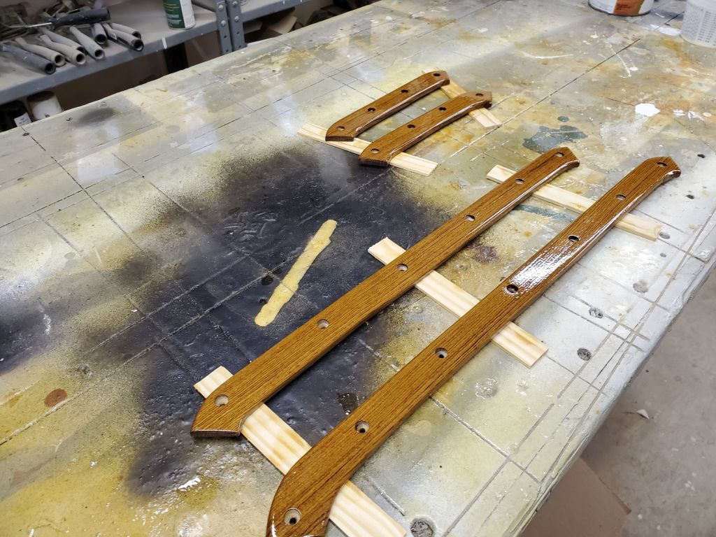
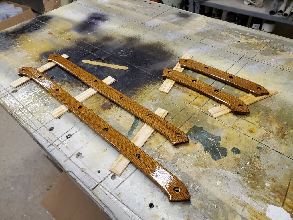
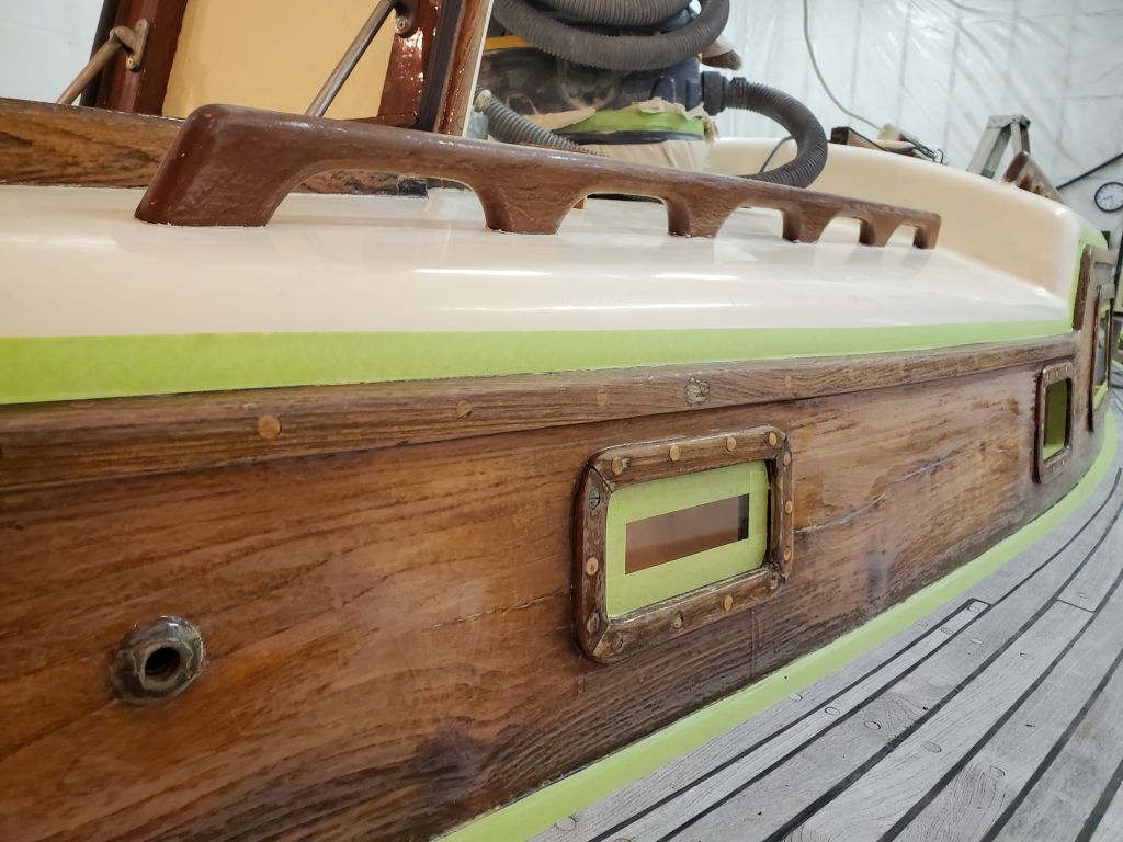
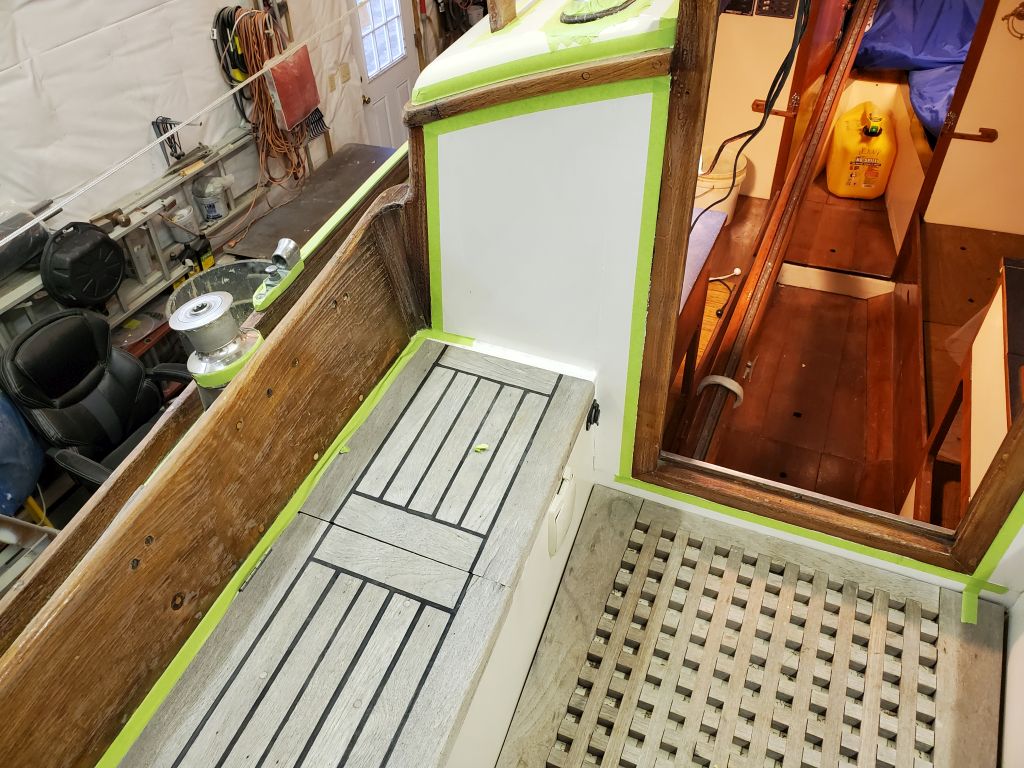
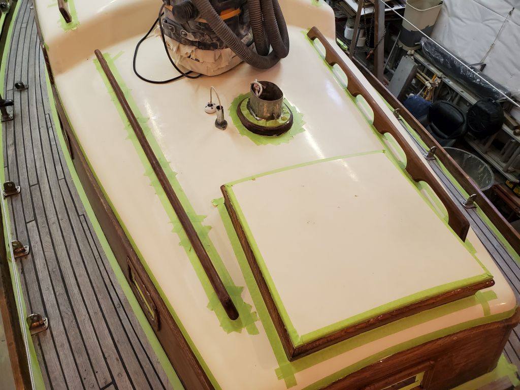
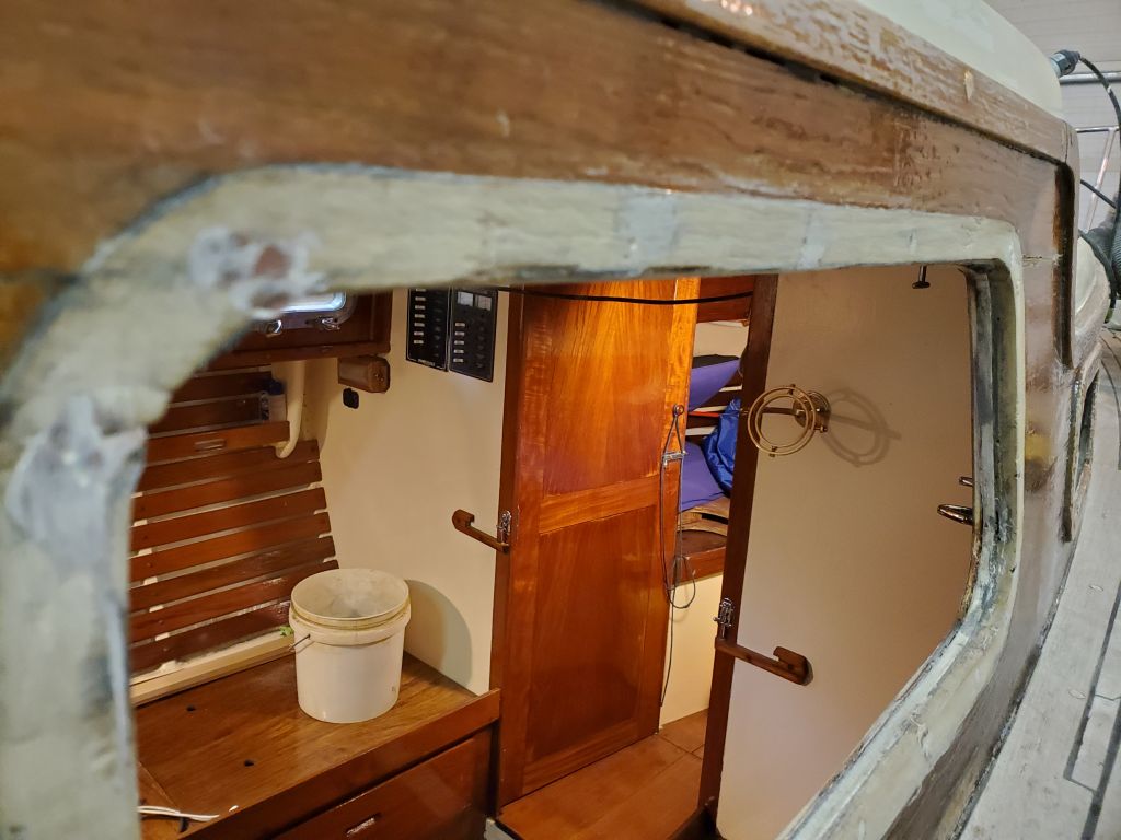
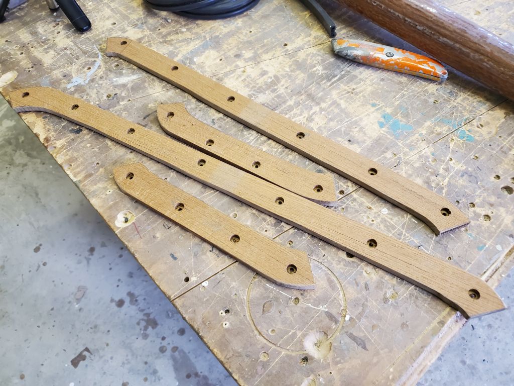
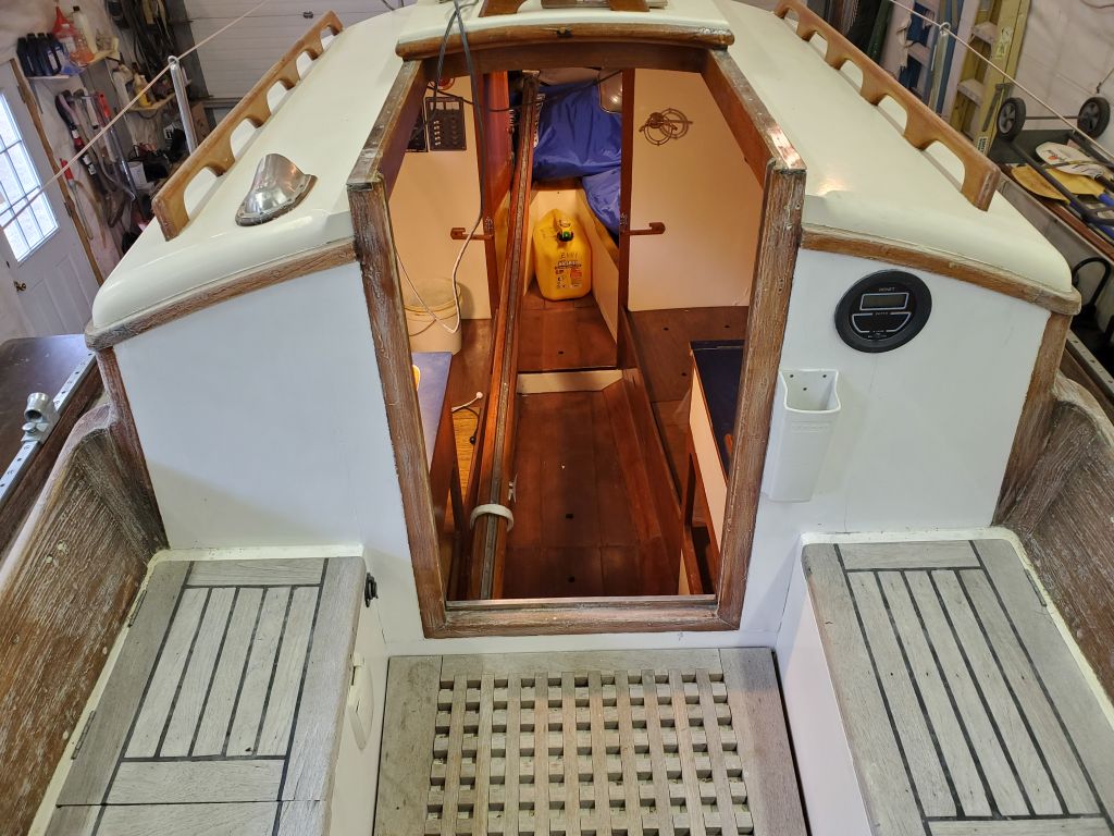
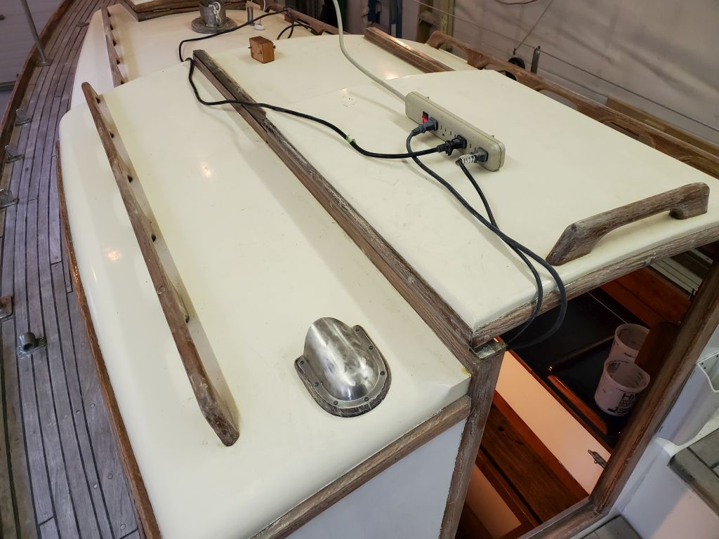
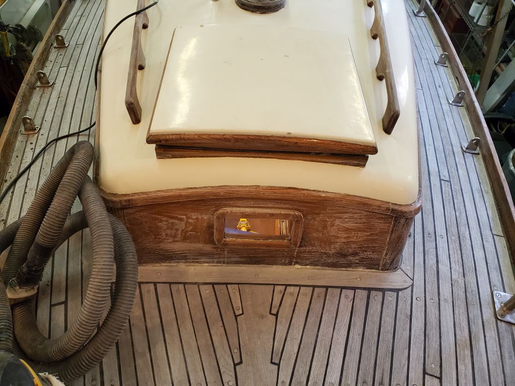
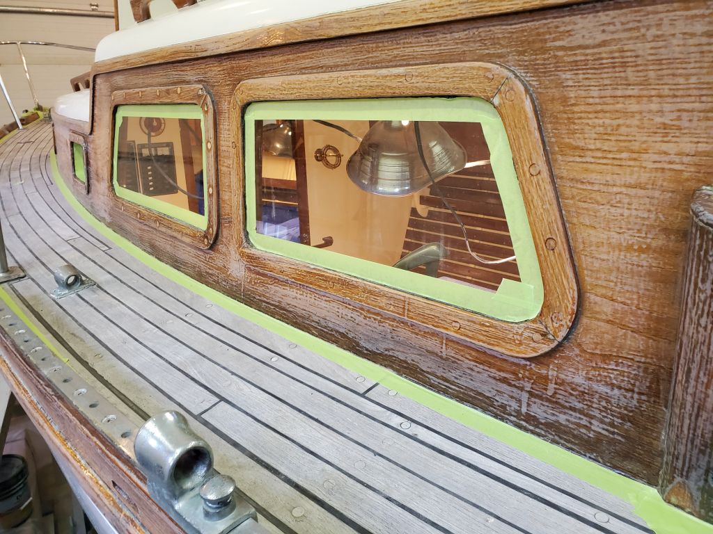
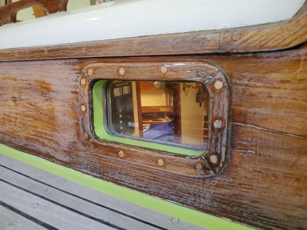
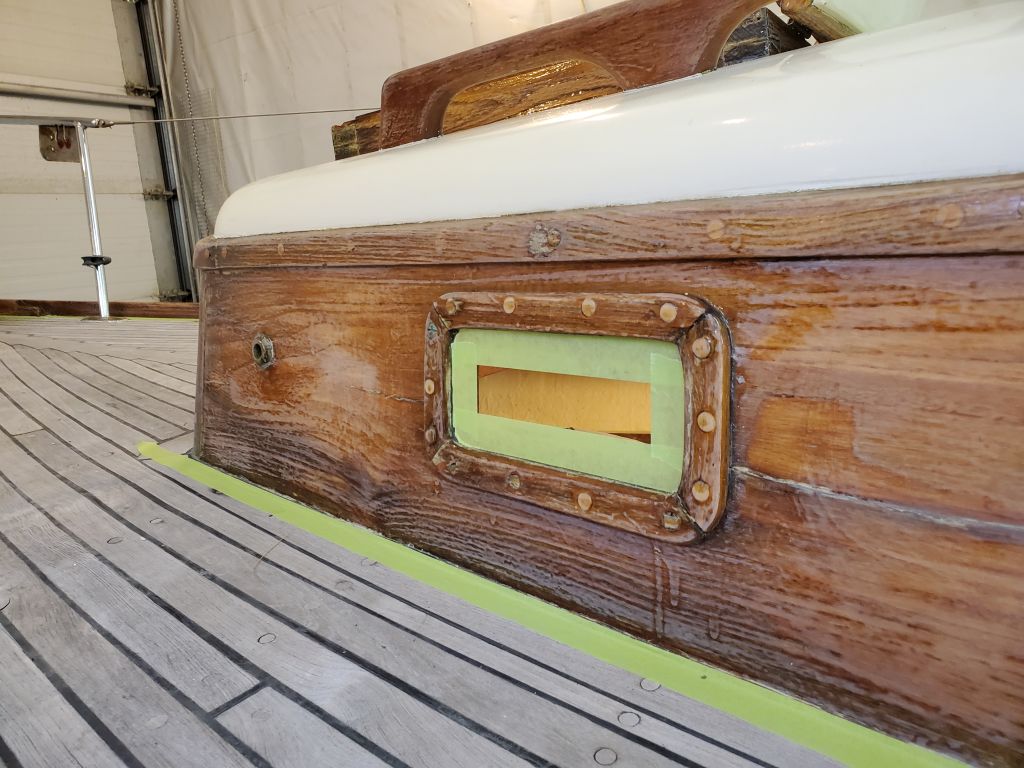
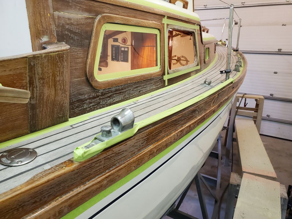
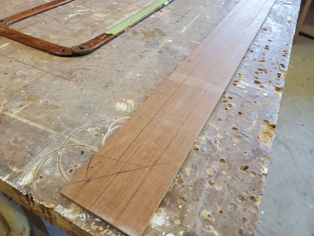
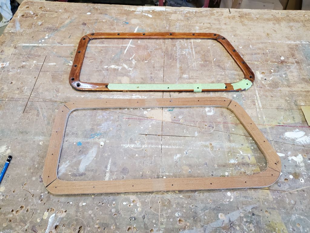
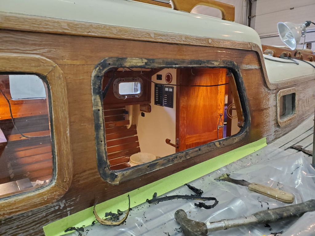
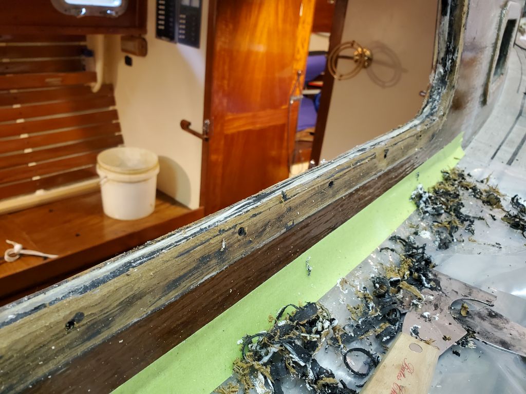
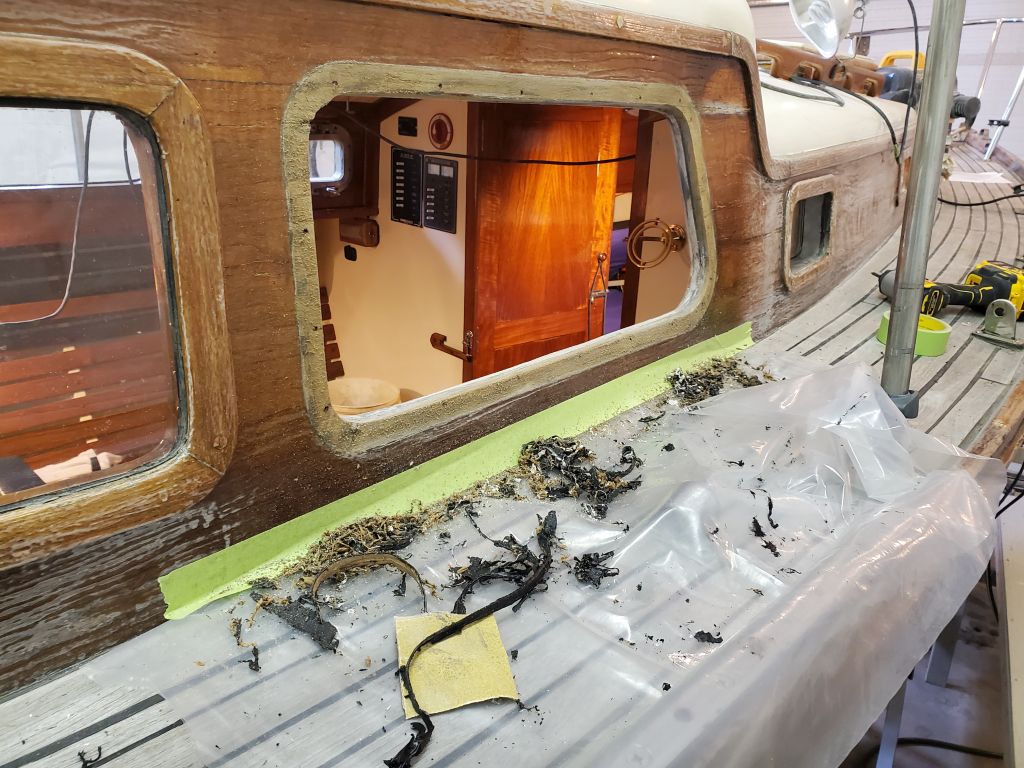
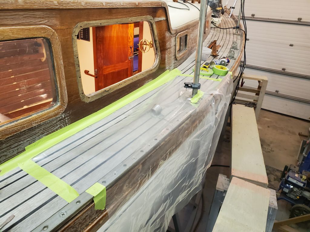
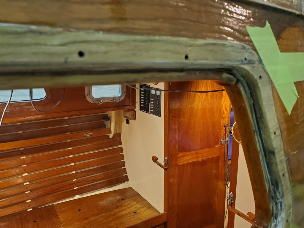
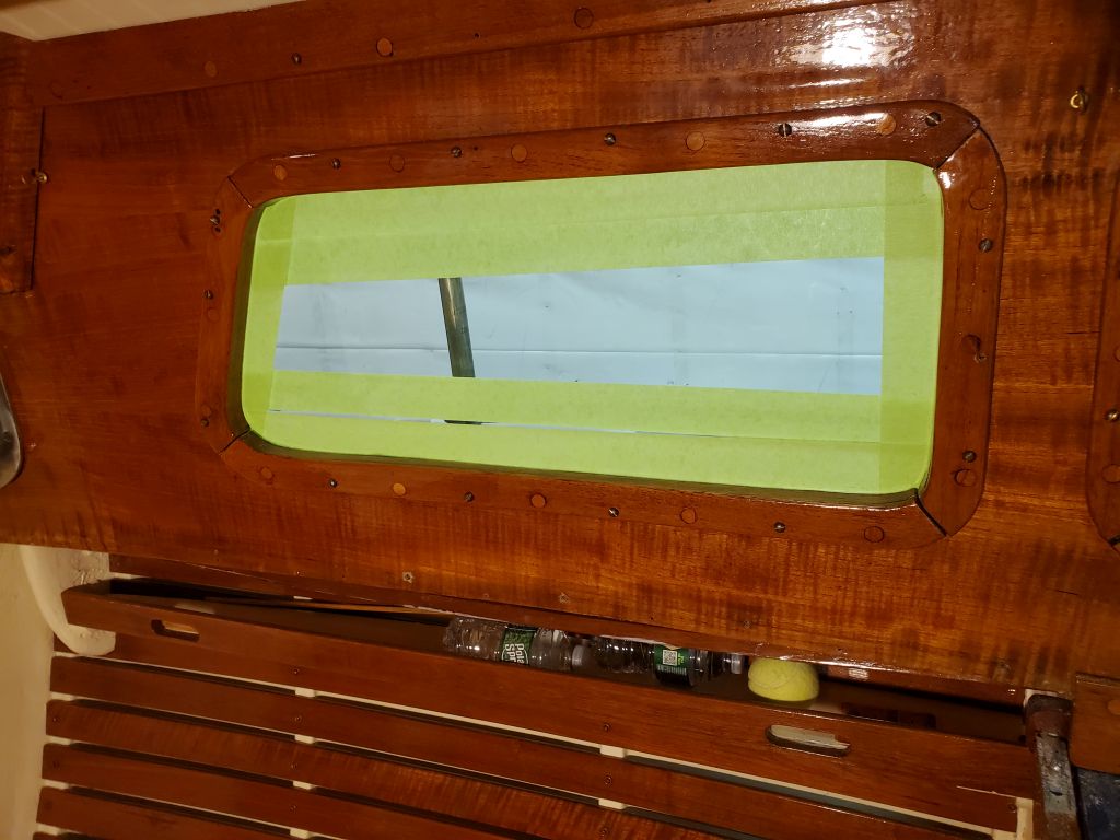
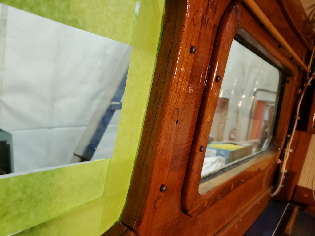
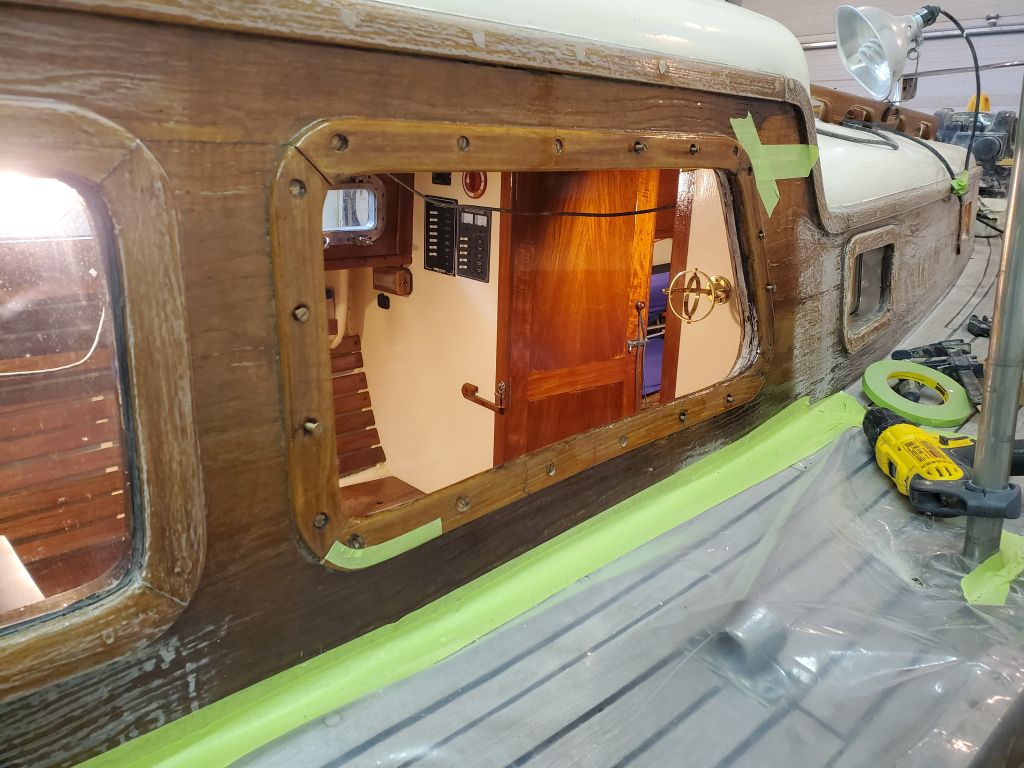
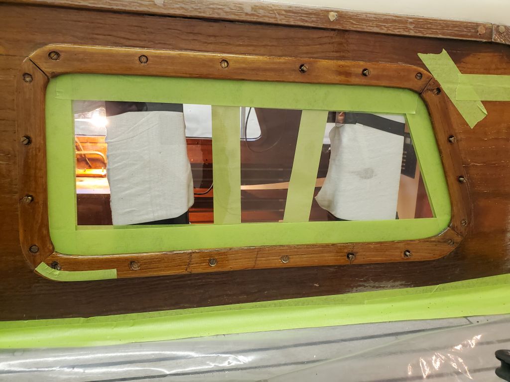
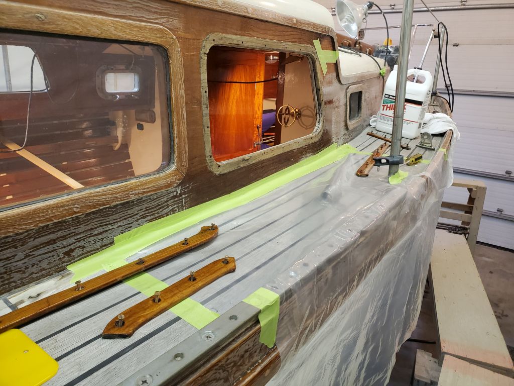
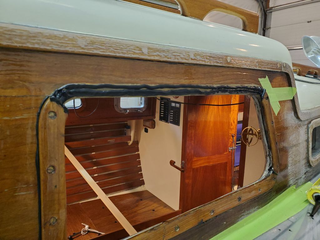
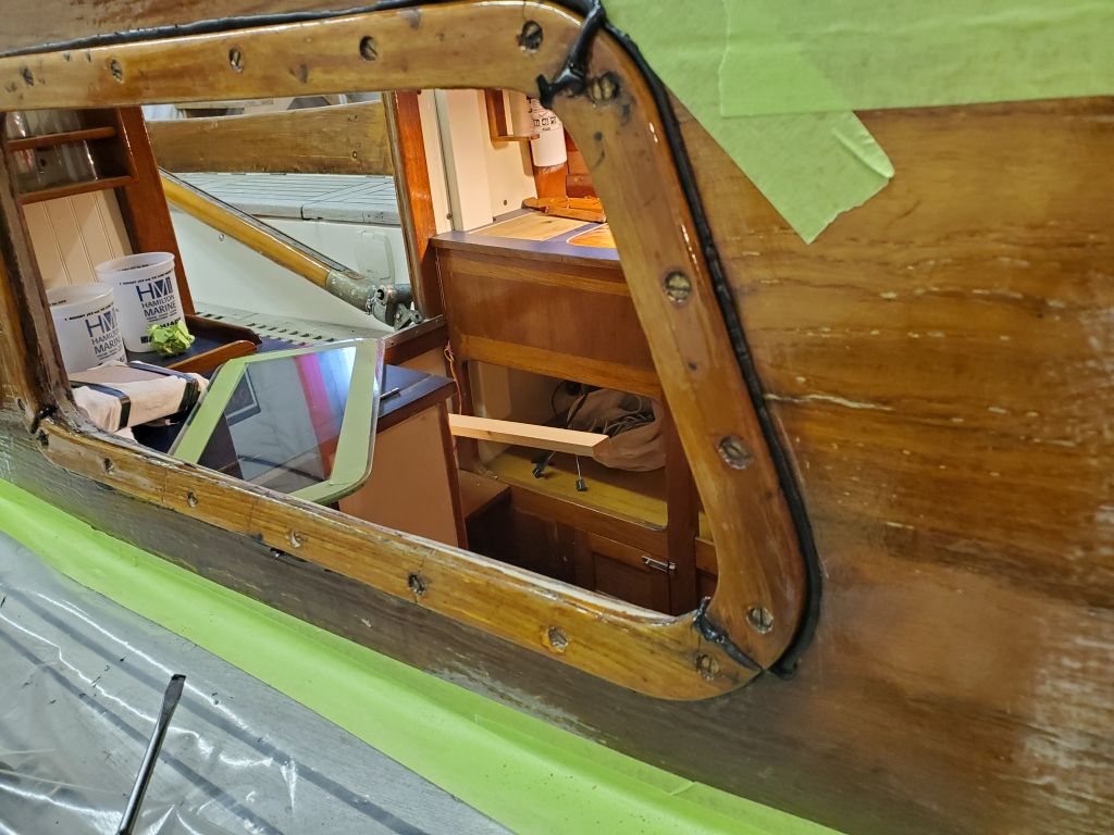
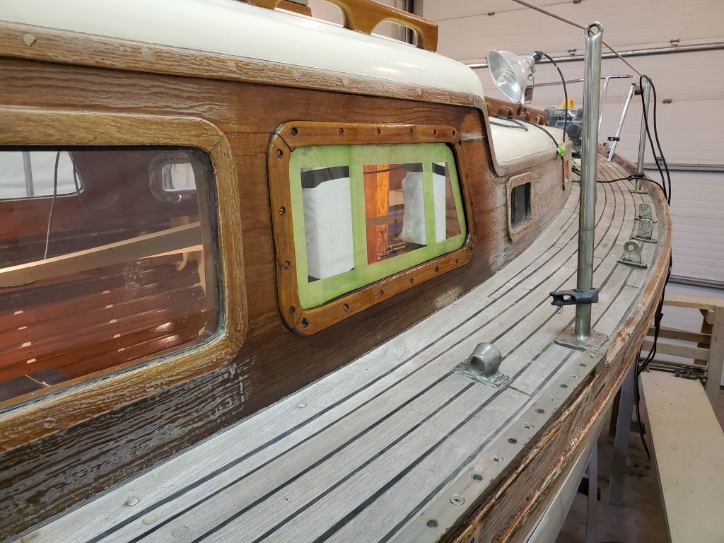
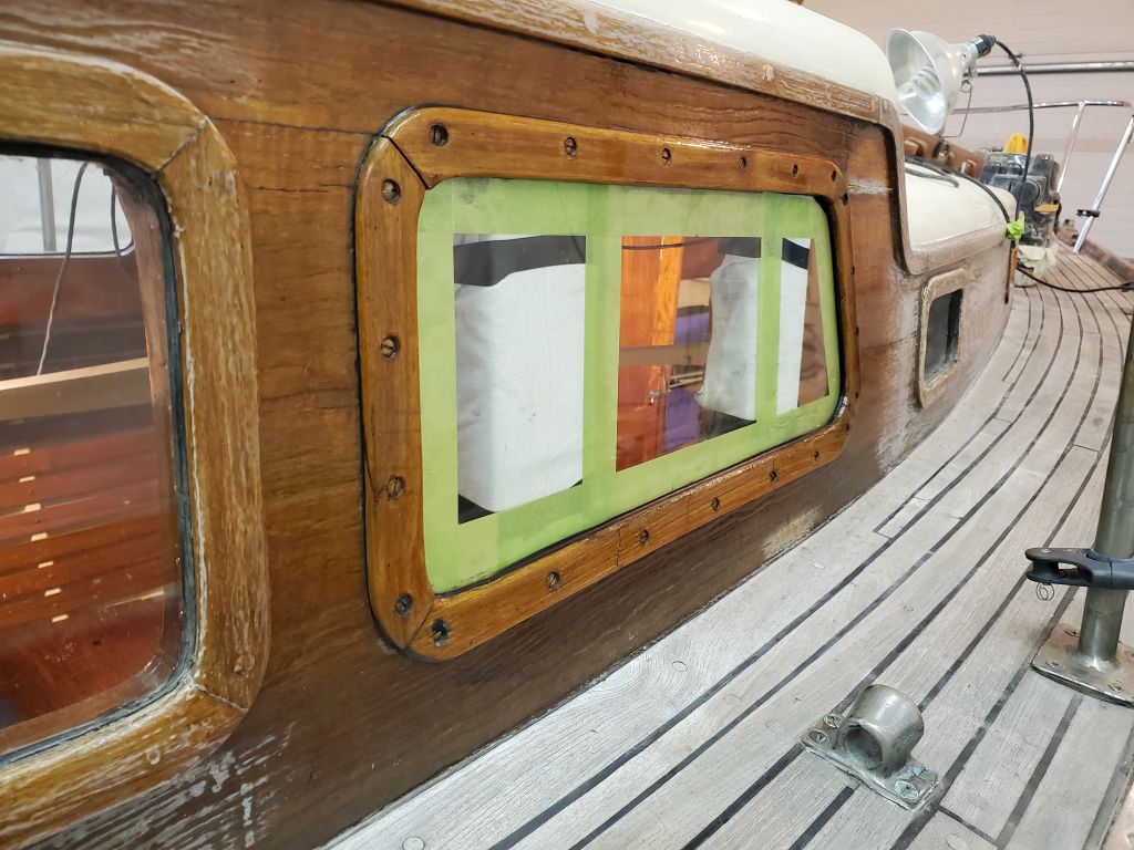
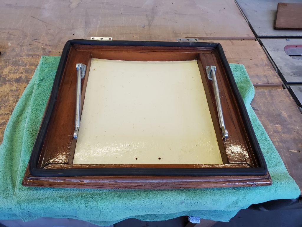
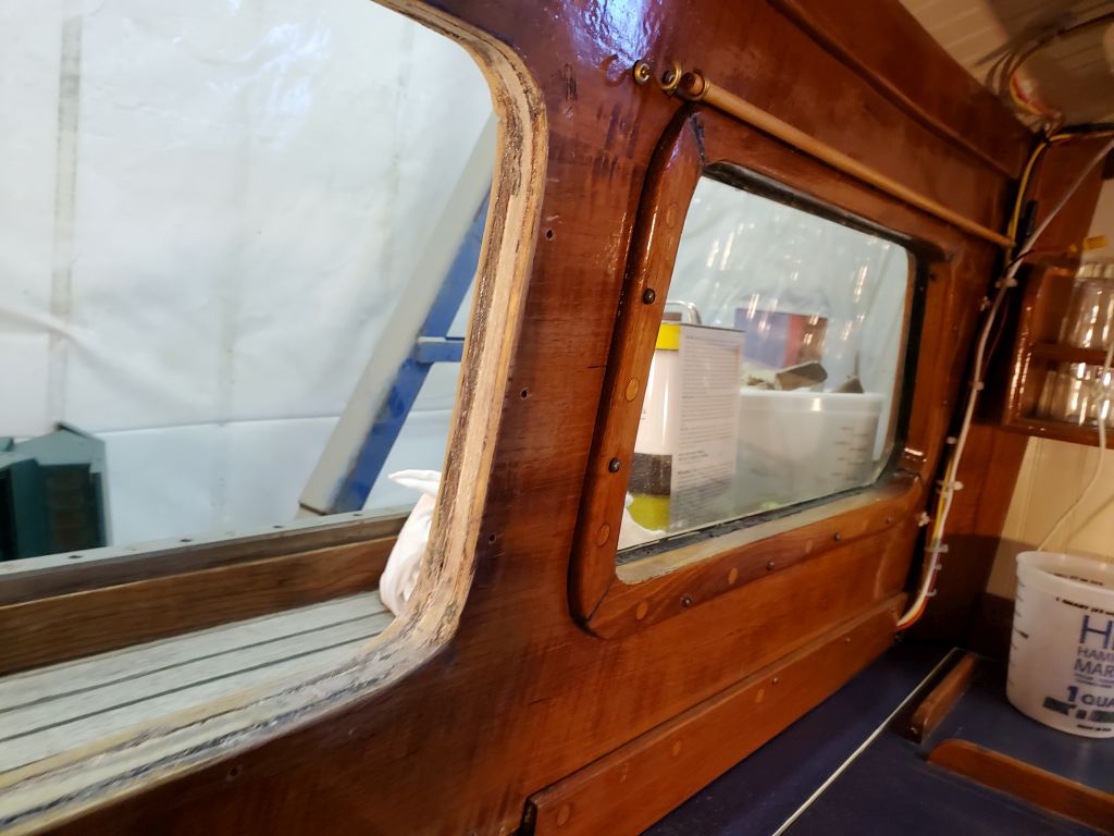
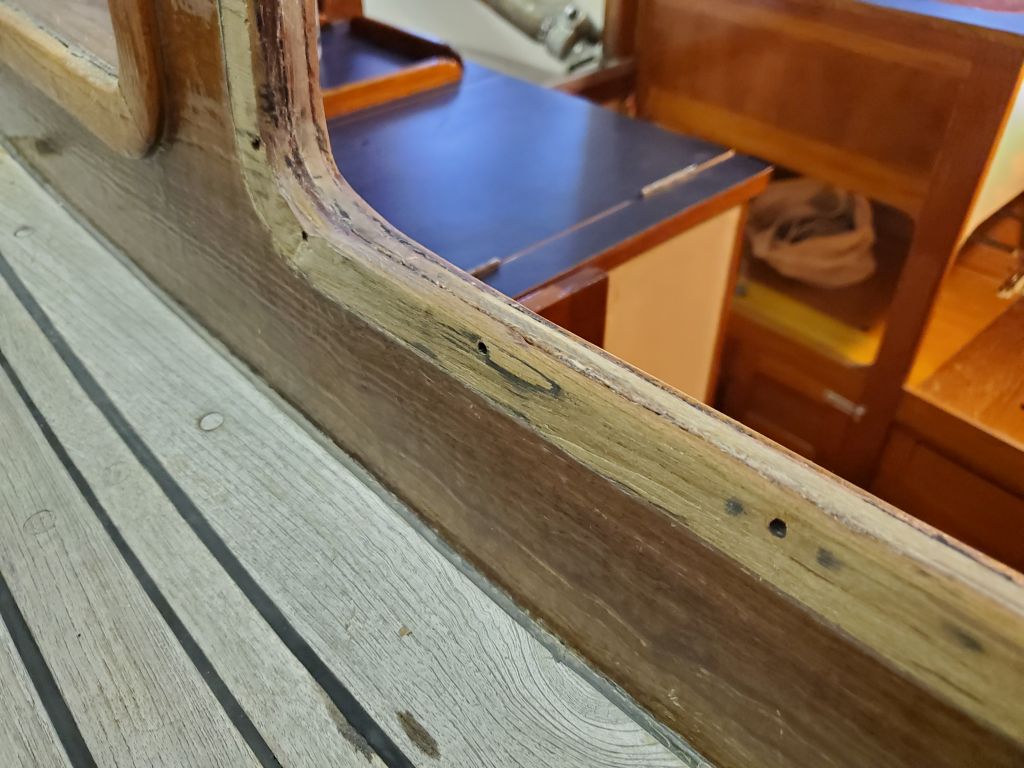
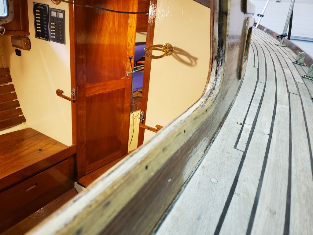
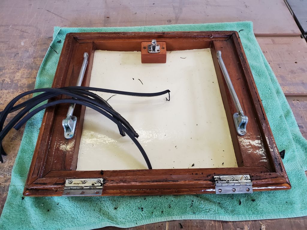
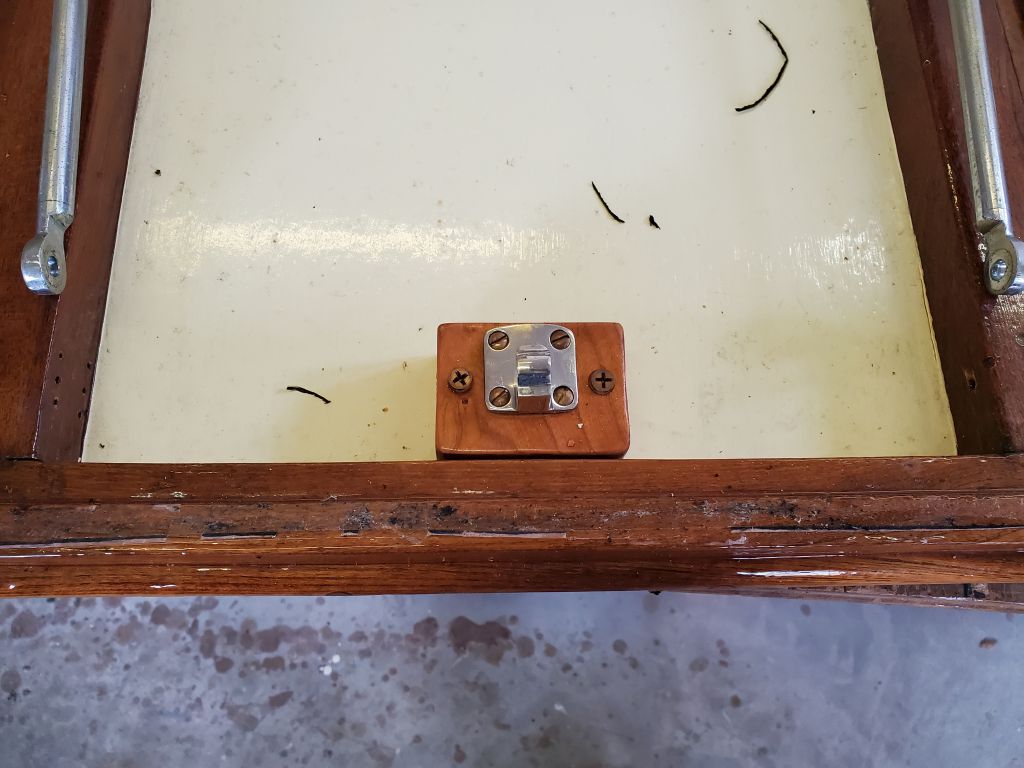
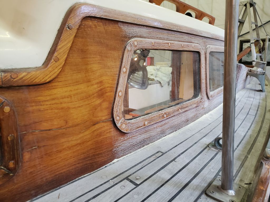
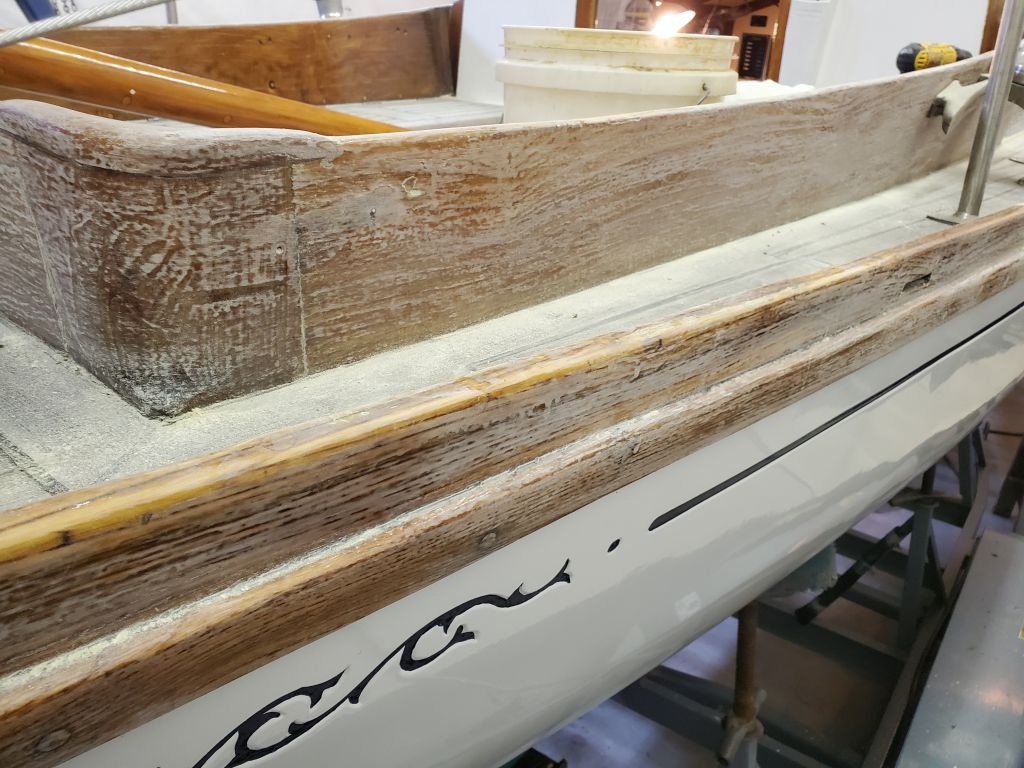
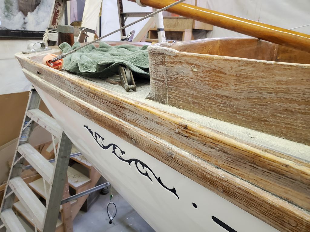
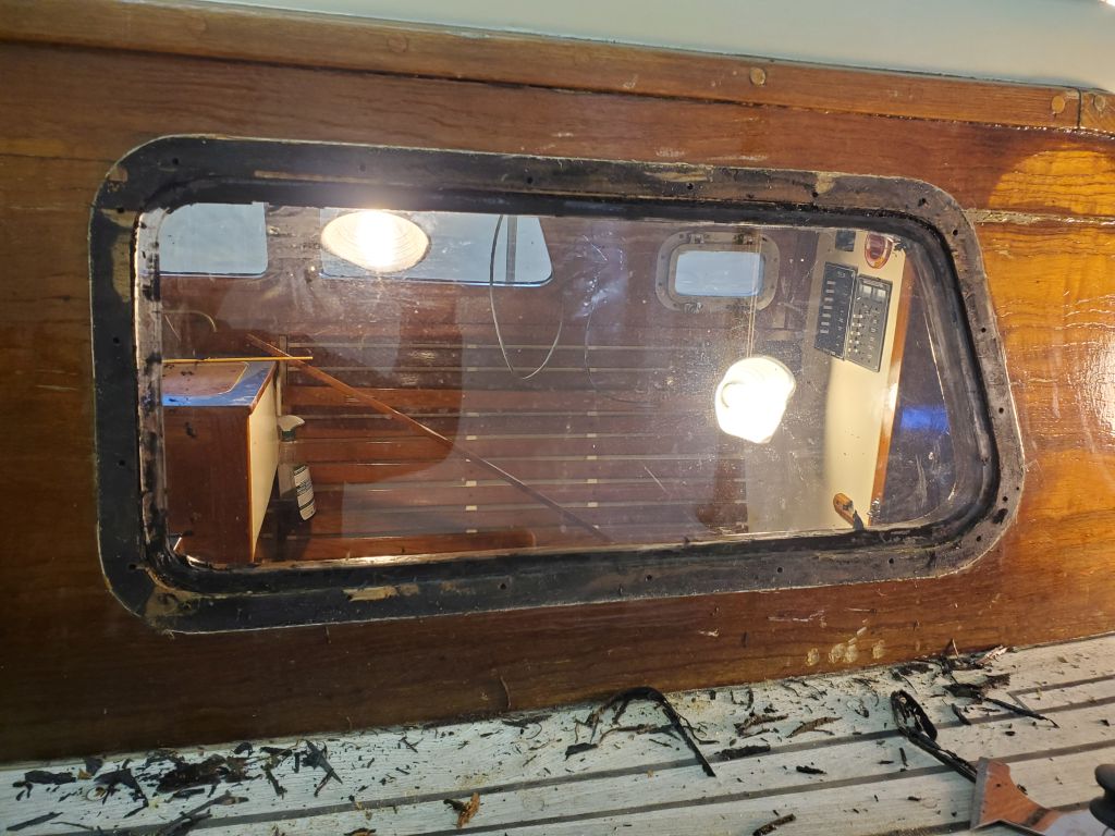
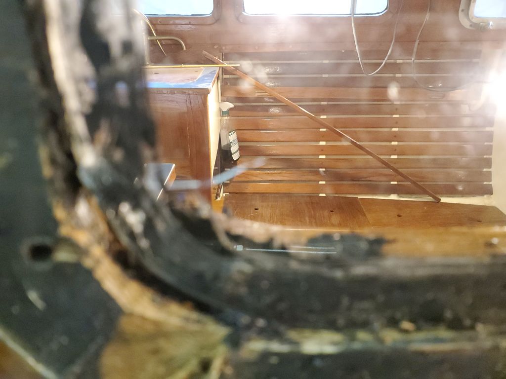
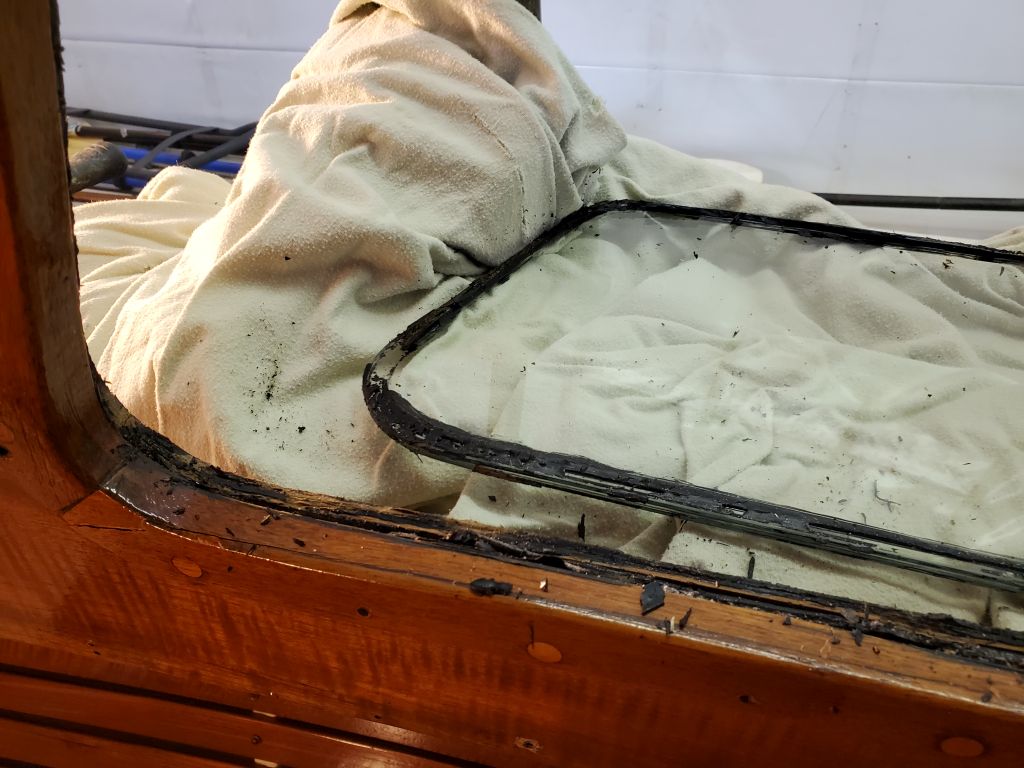
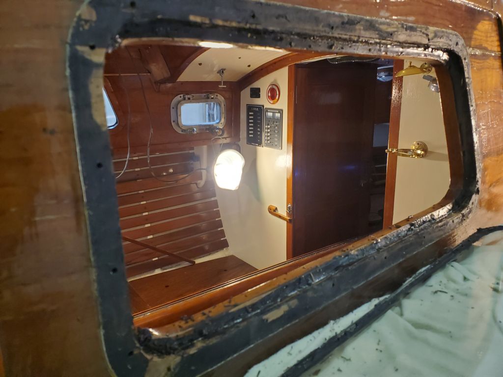
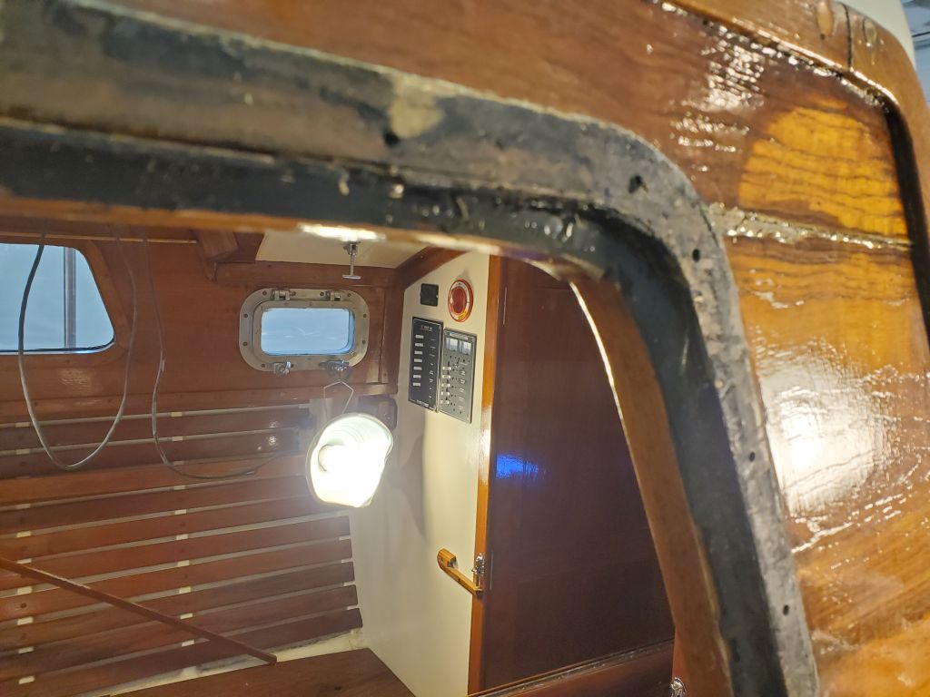
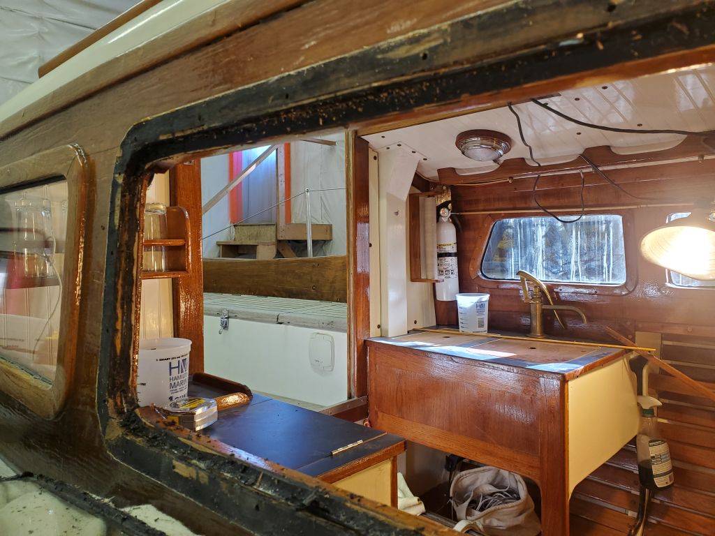
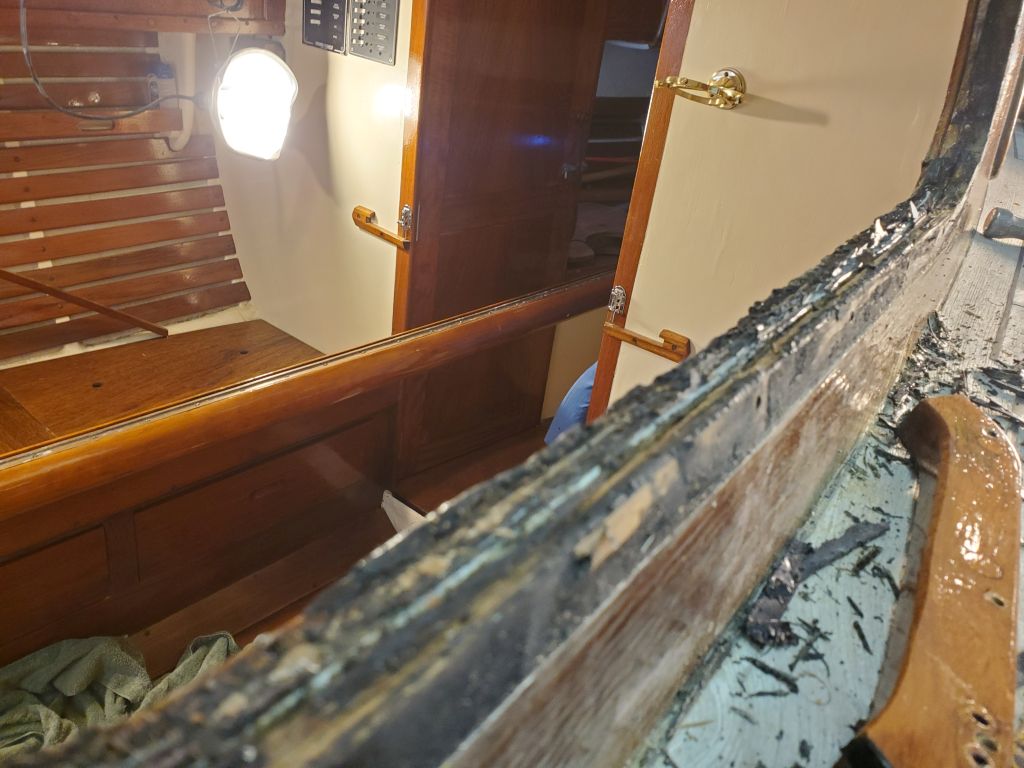
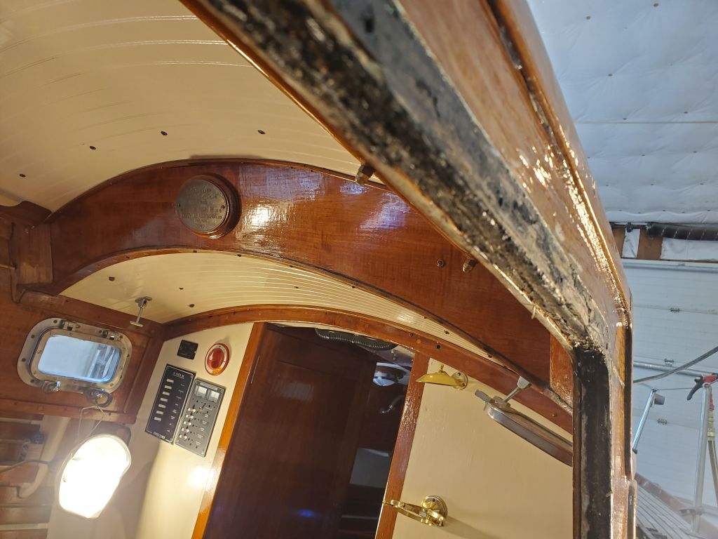
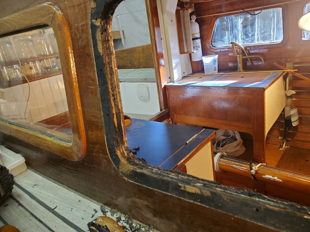
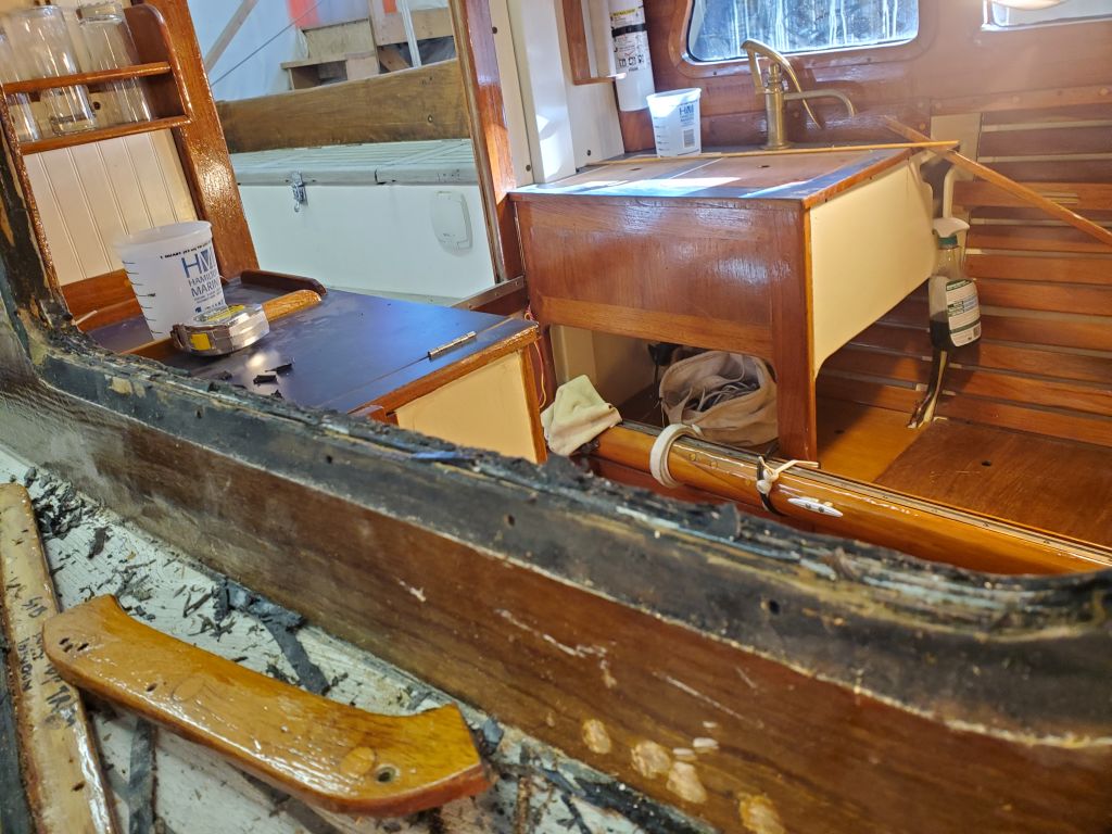
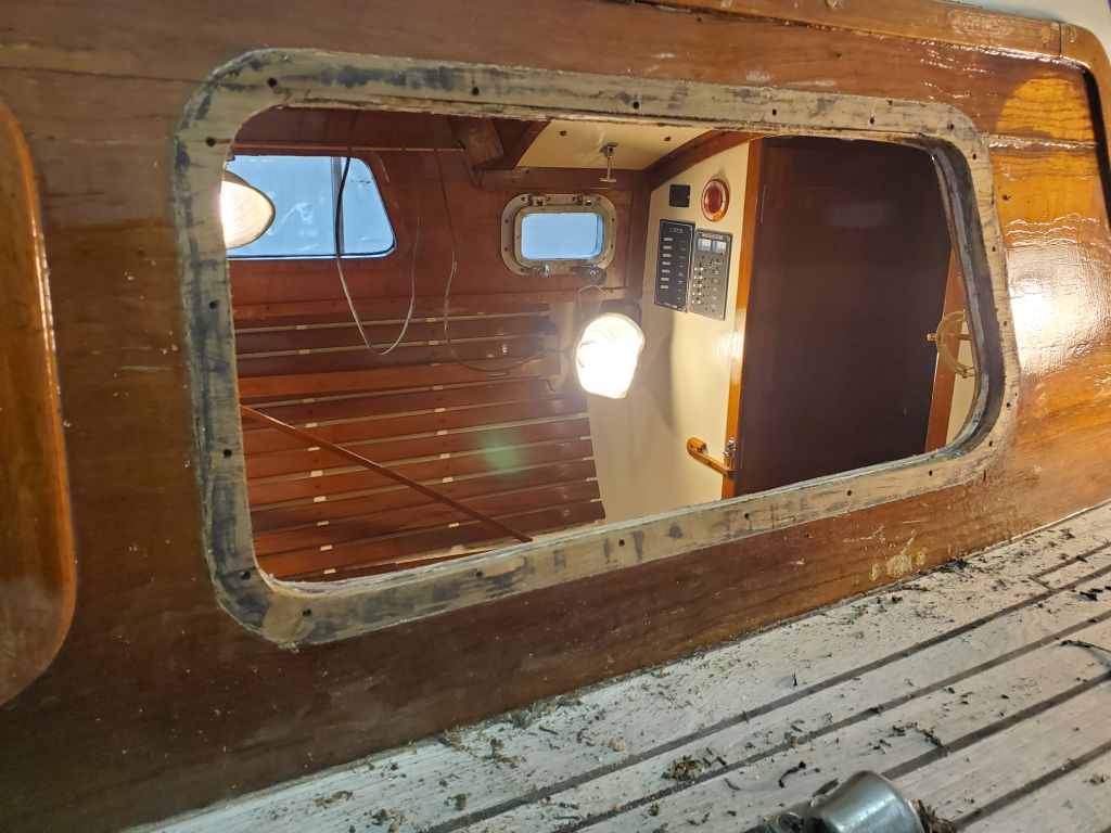
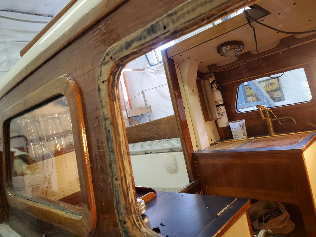
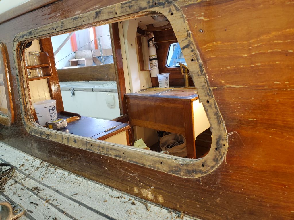
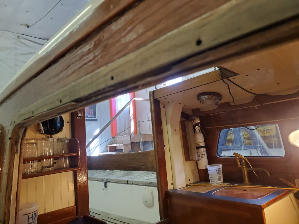
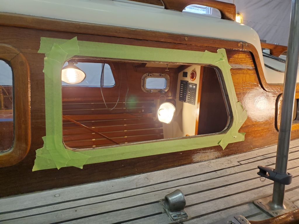
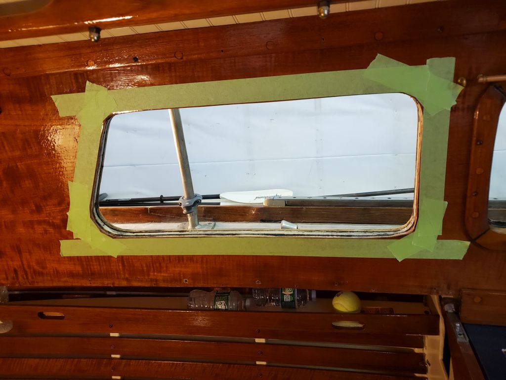
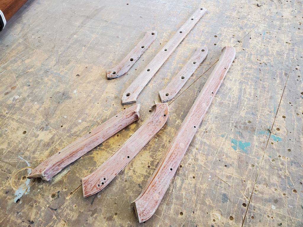
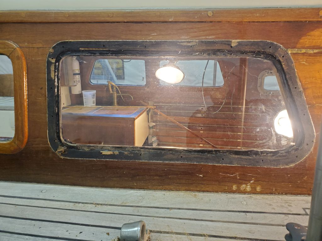
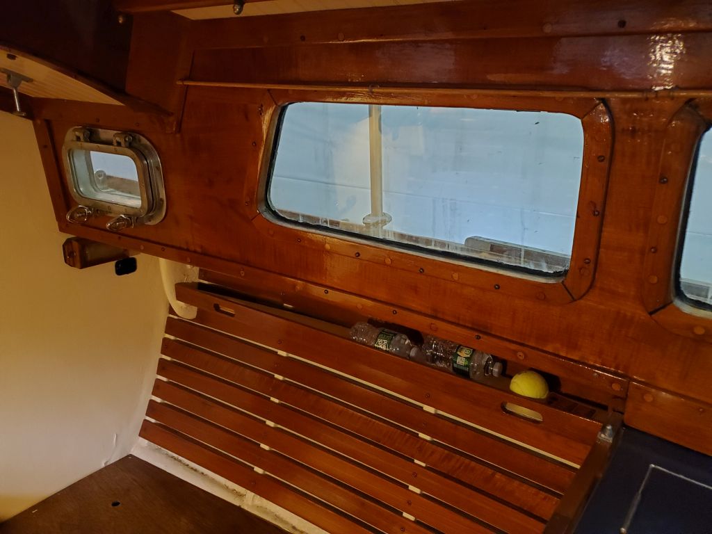
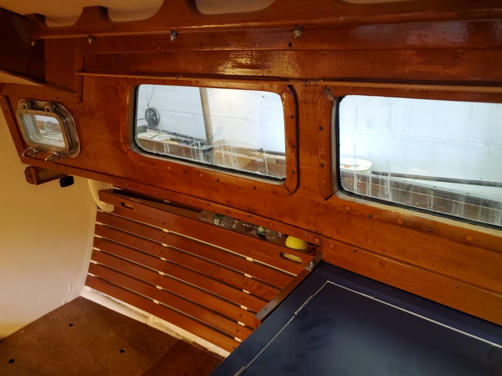
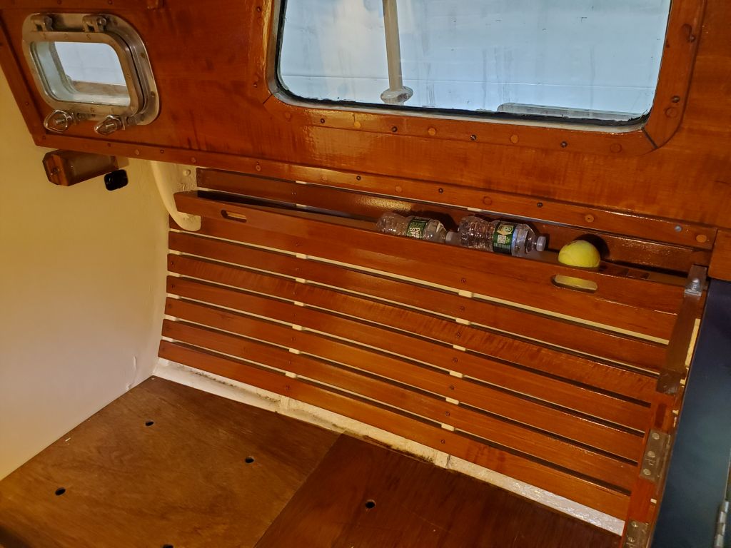
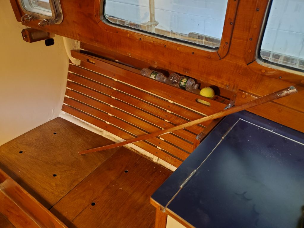
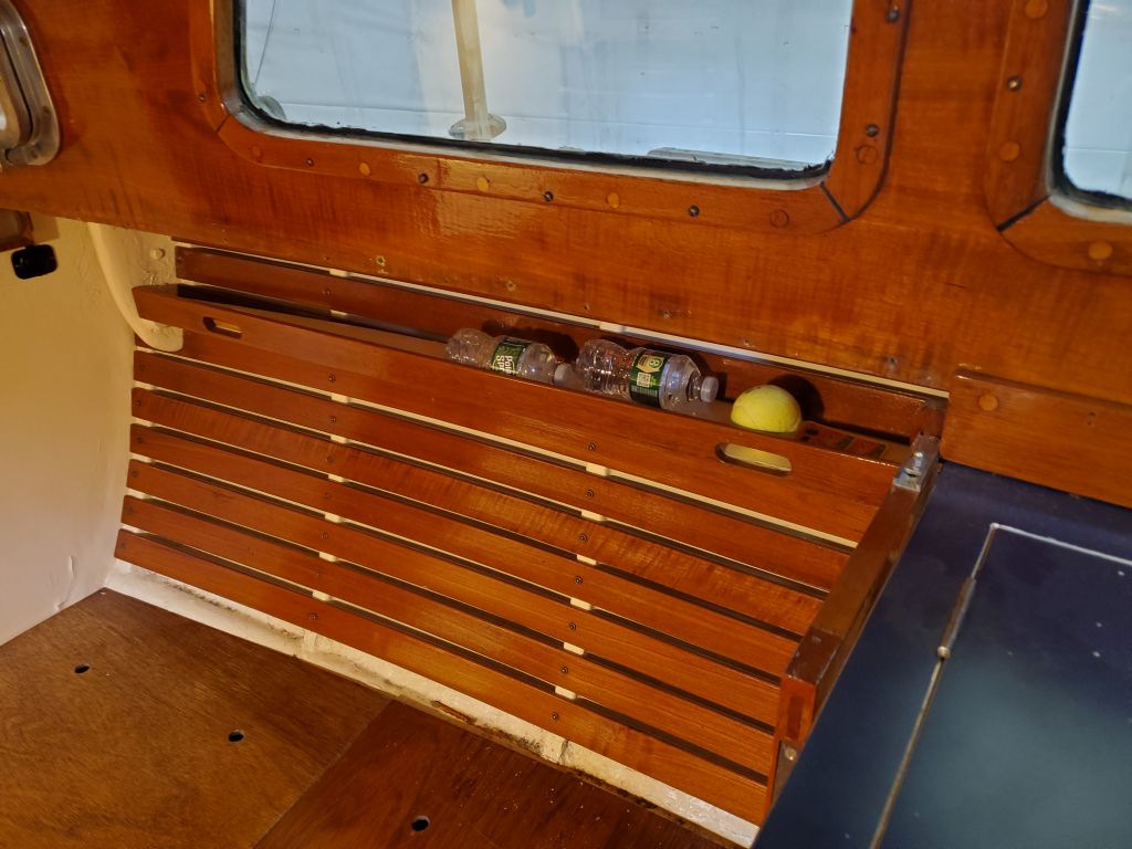
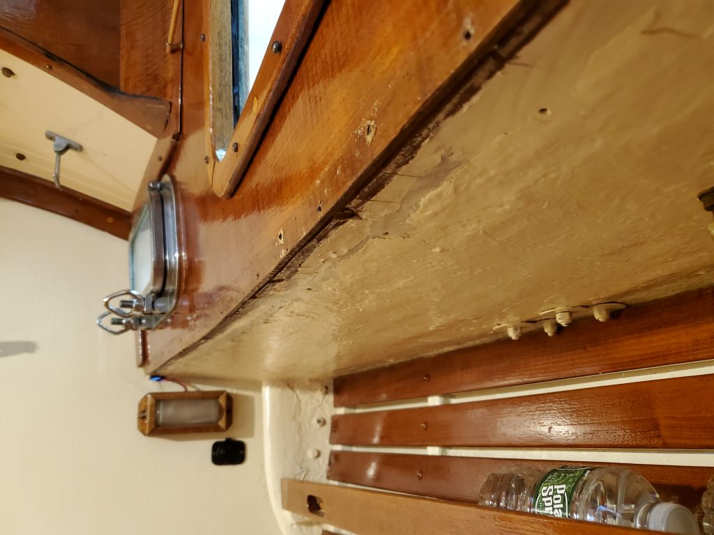
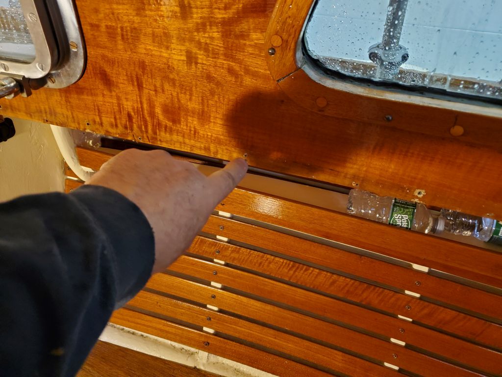
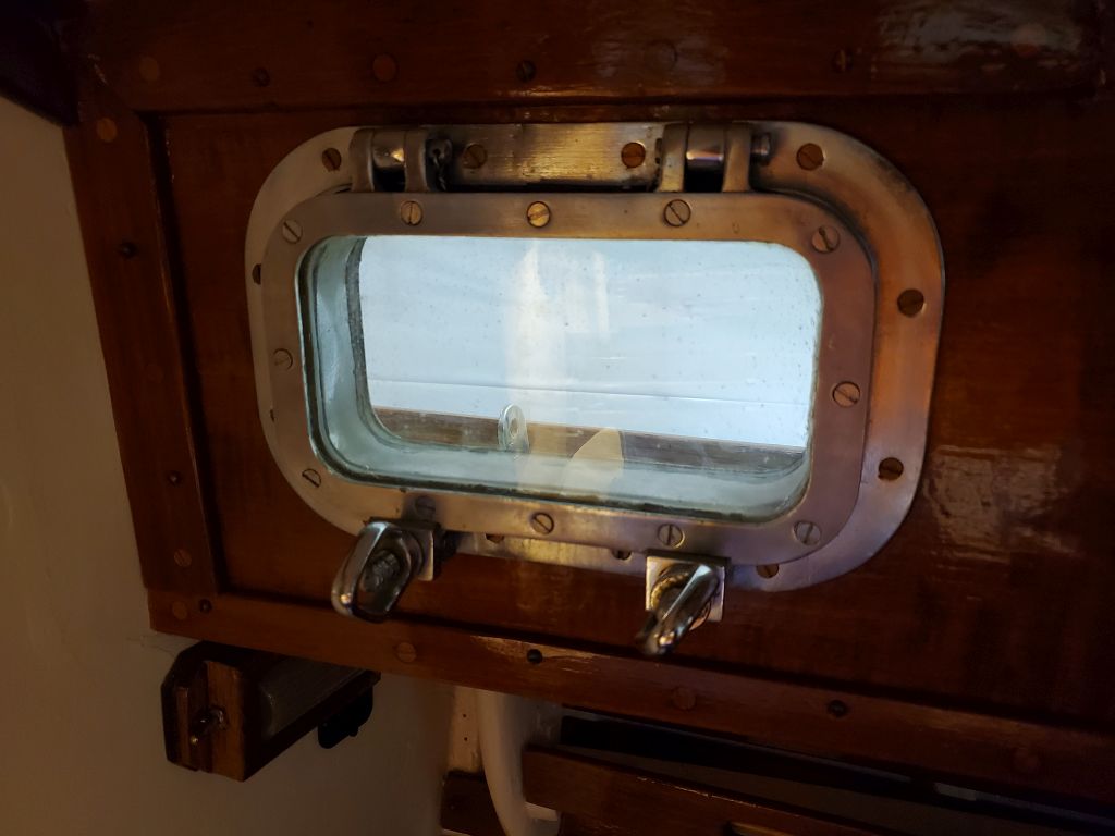
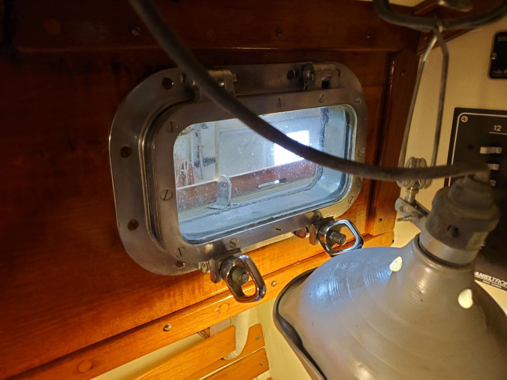
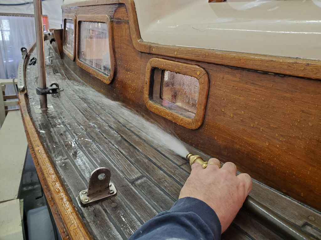
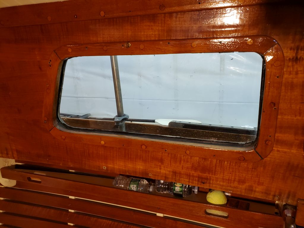
Preparing to install and rebed the deadlight, I started by masking down a sheet of plastic to cover the deck and environs for protection during the work. Then, I installed the interior trim to give the deadlight frame the bearing surface needed for installation.

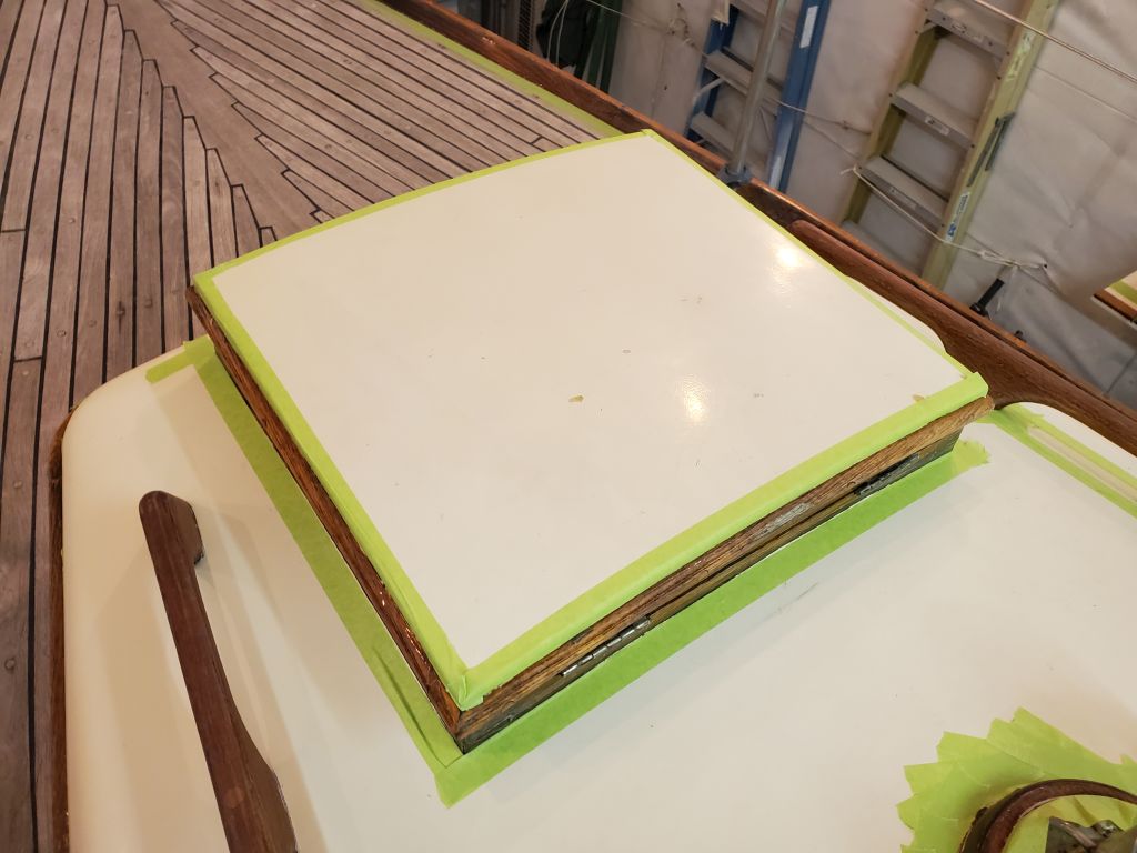
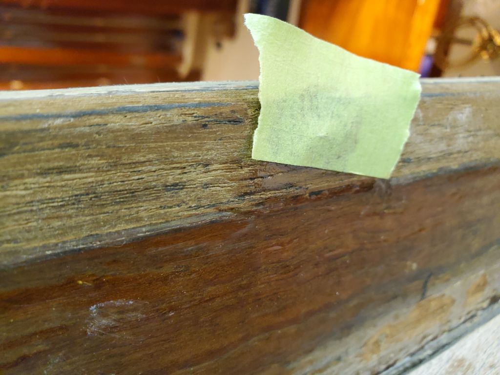
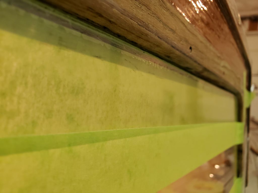
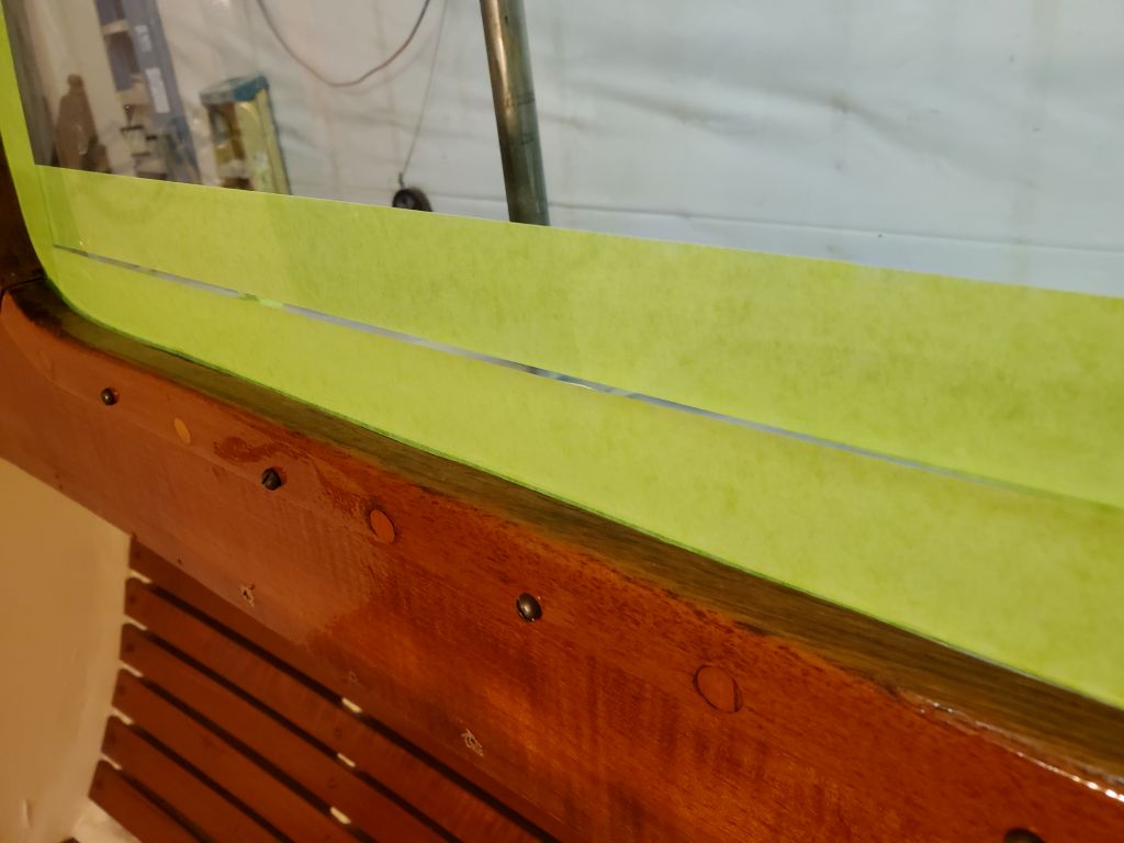
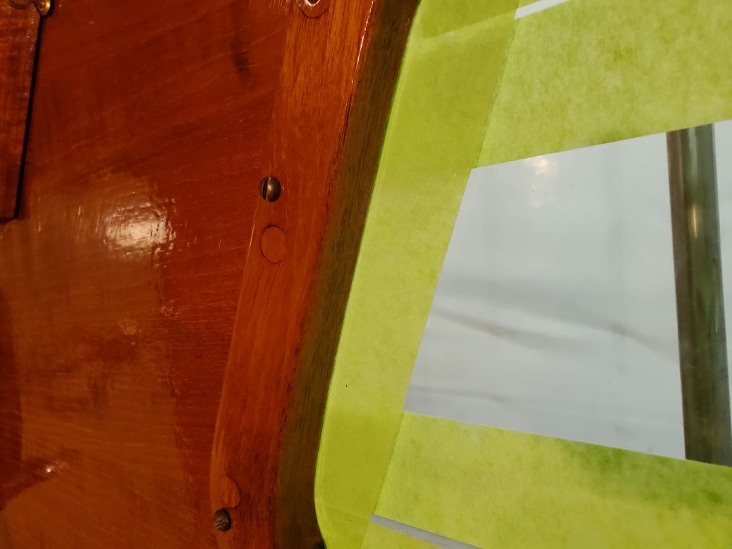
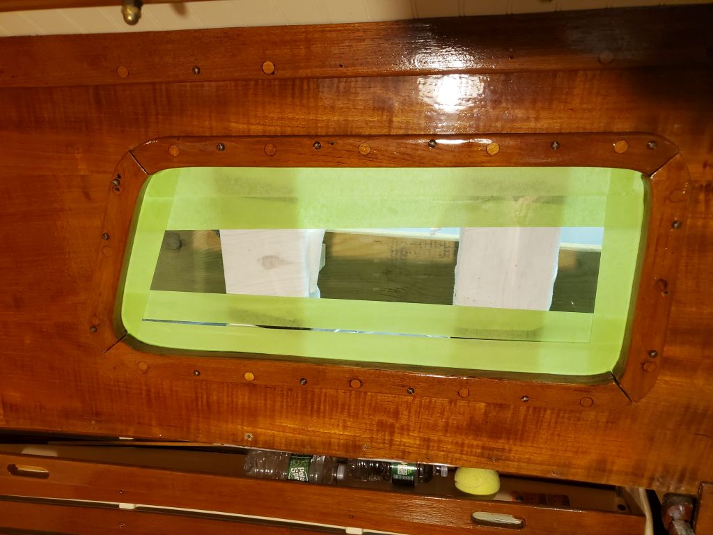
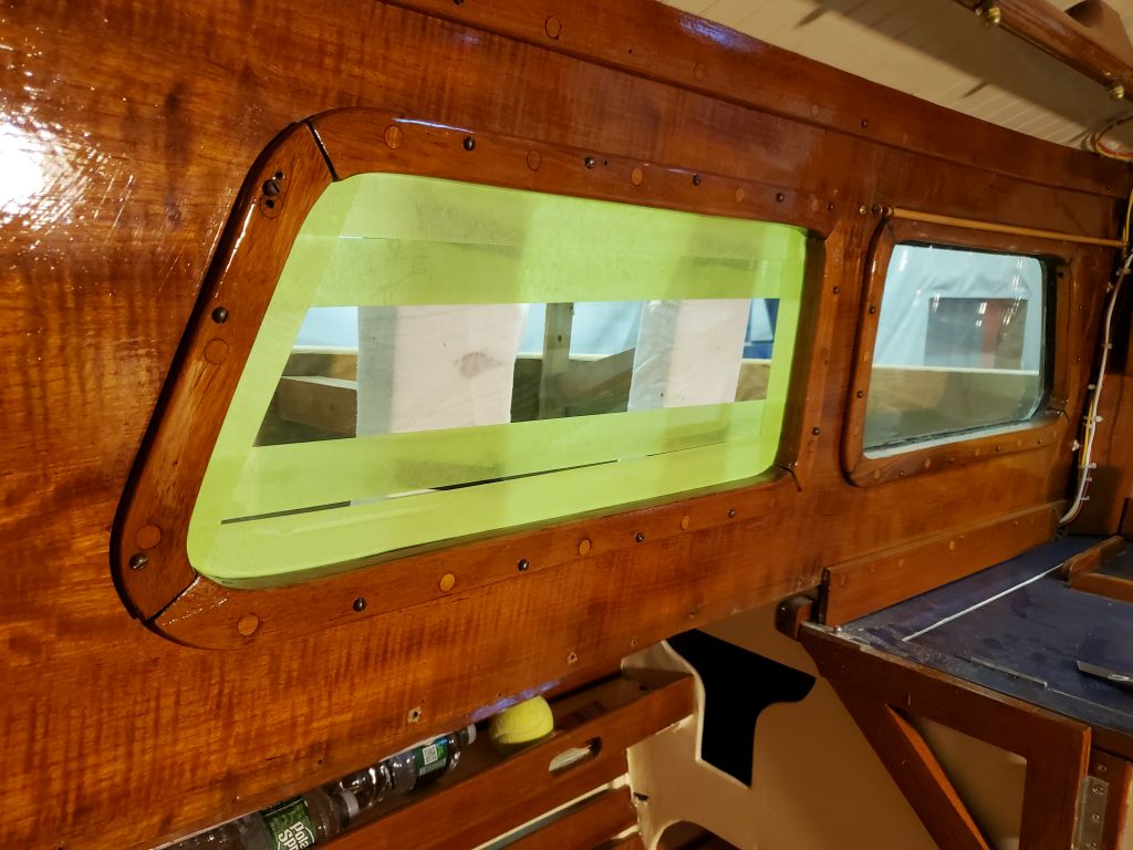
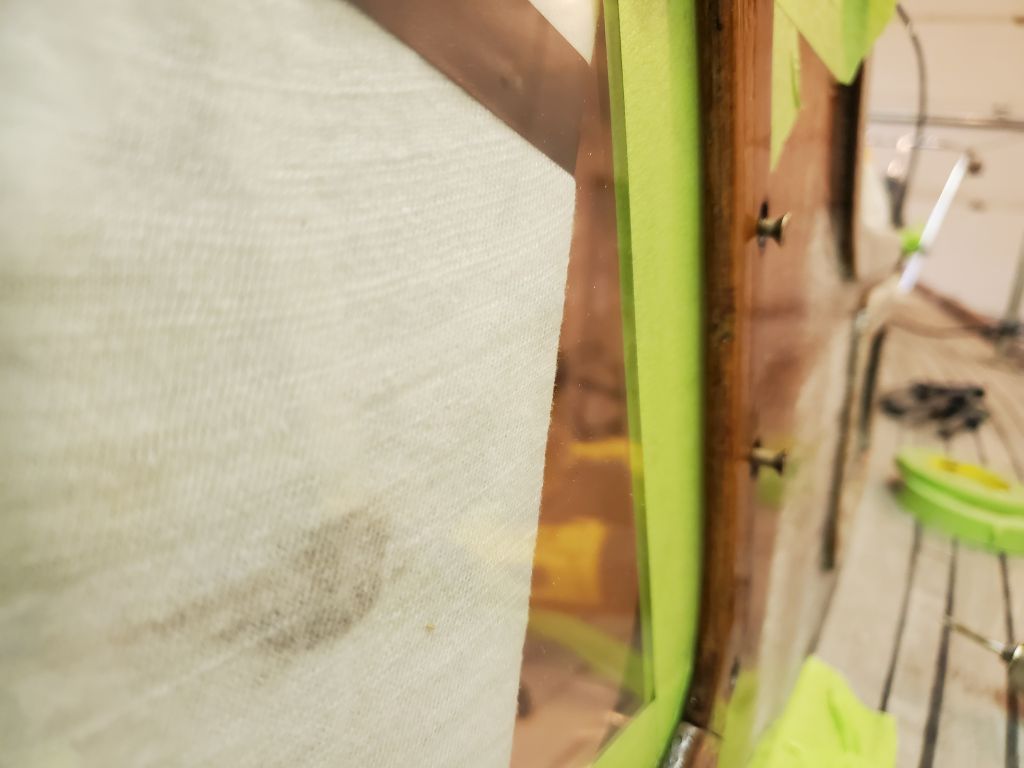
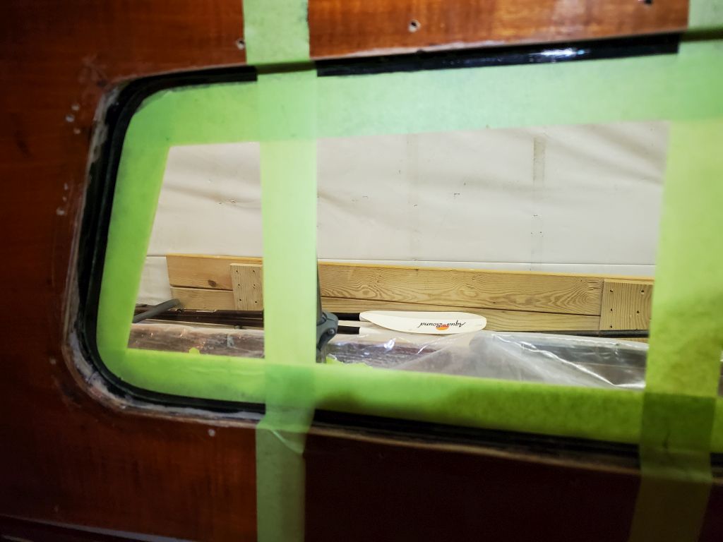
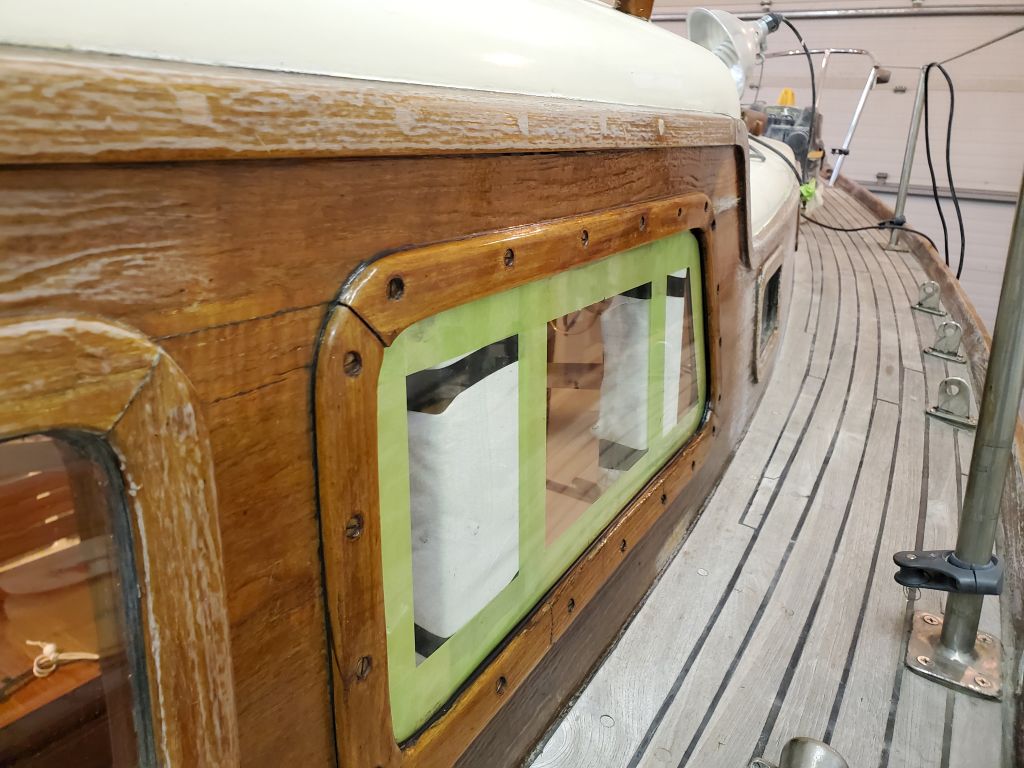
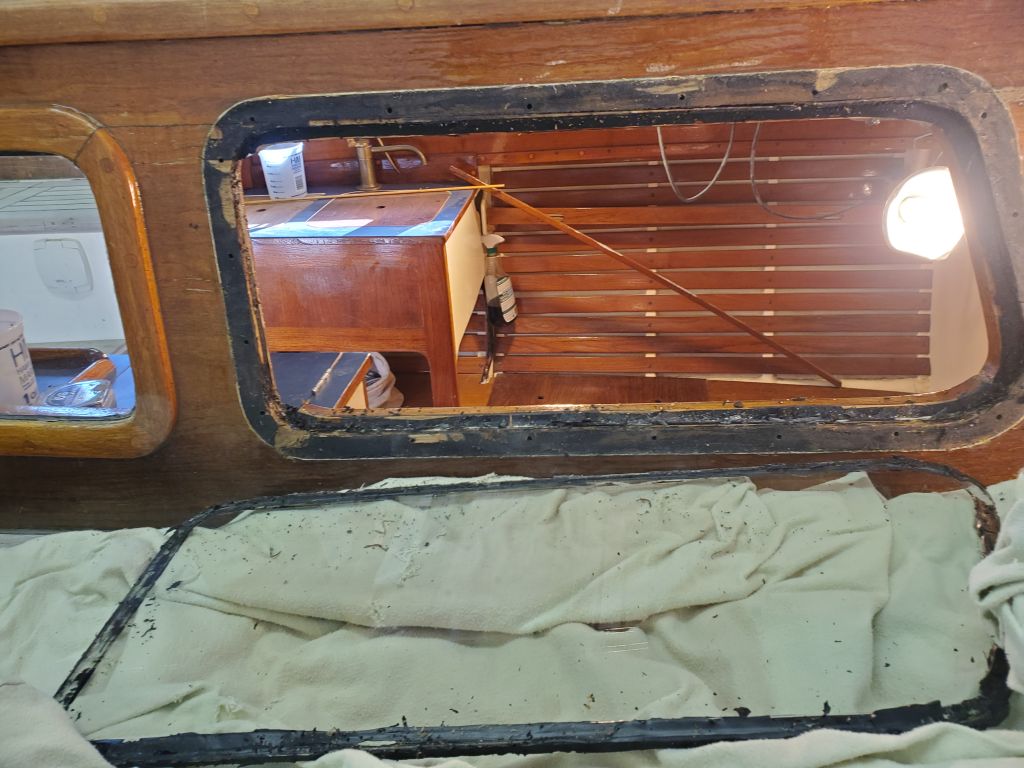
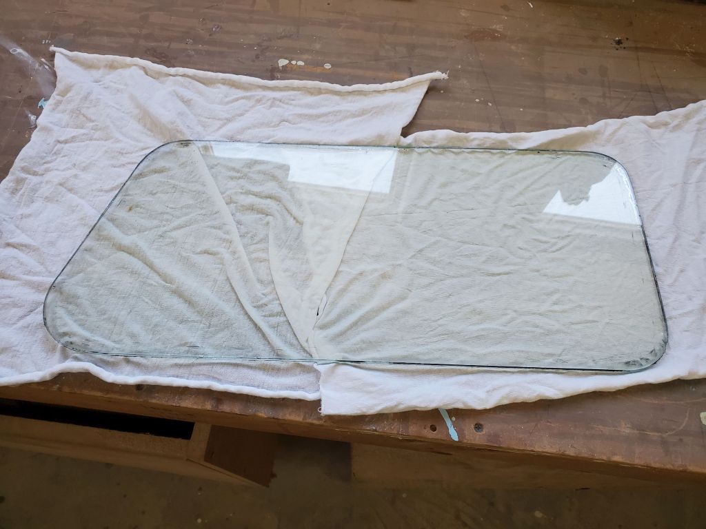
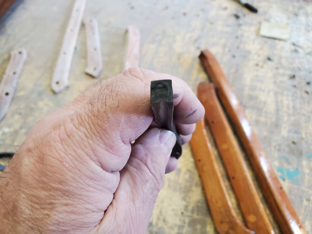
Working from outside, I masked the inside edges of the glass lens, then set it in the opening to check the fit and trim the tape along the edge of the trim on the inside.

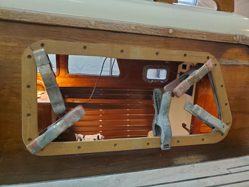
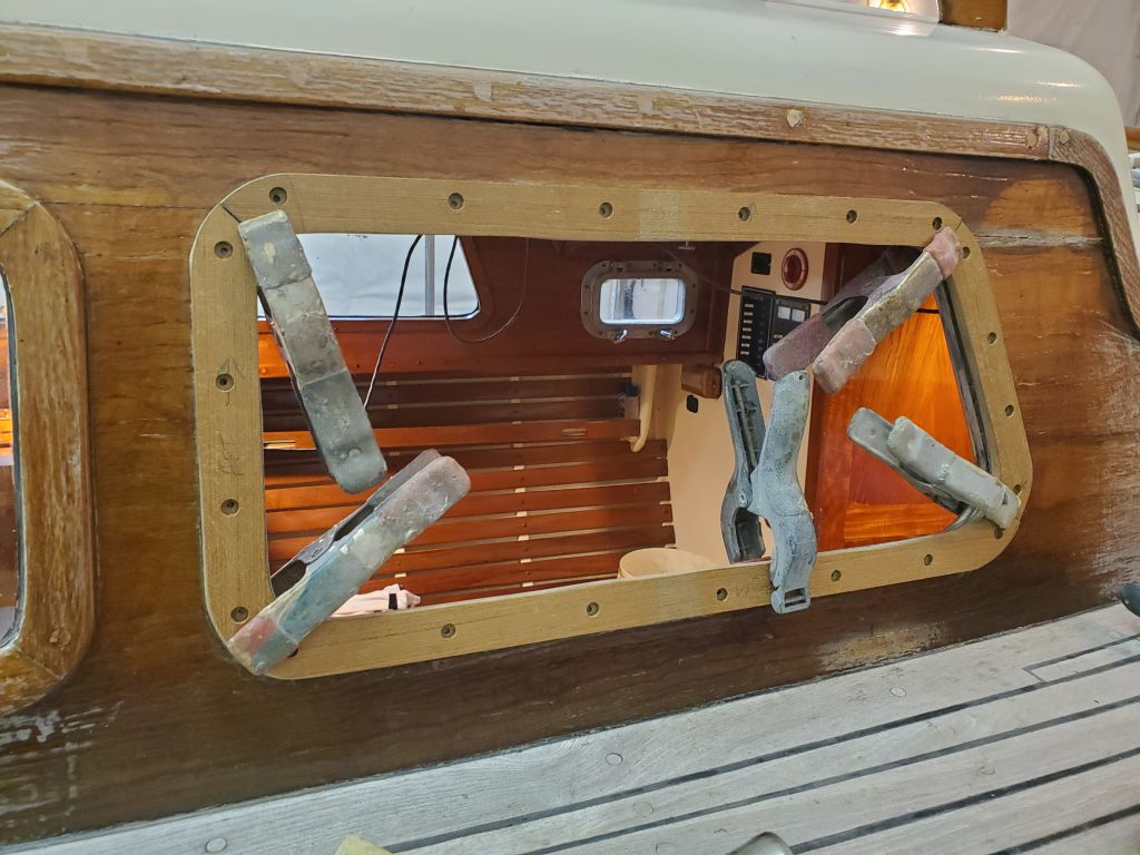
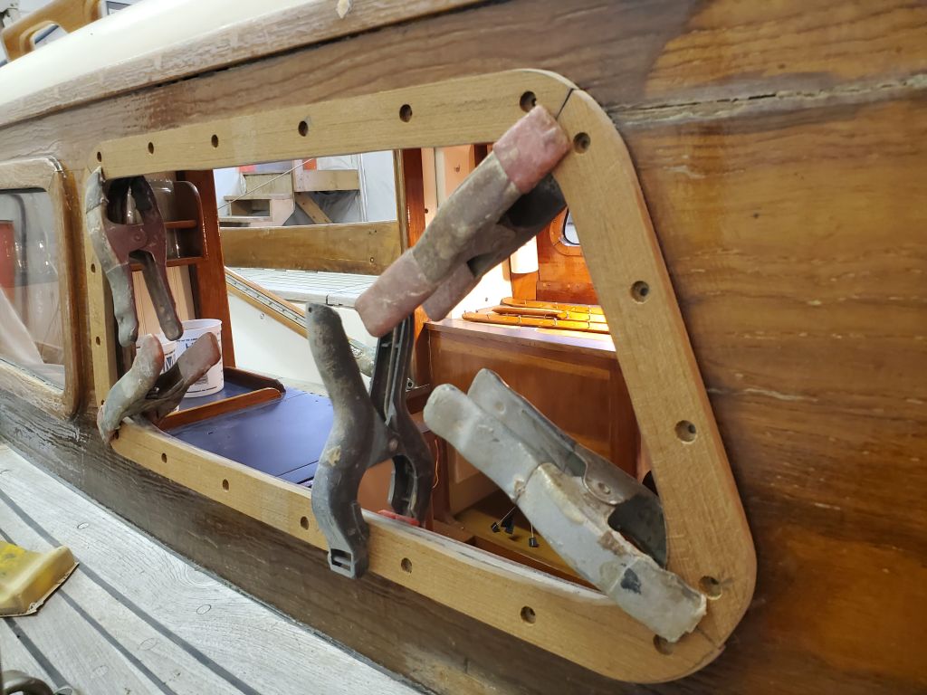
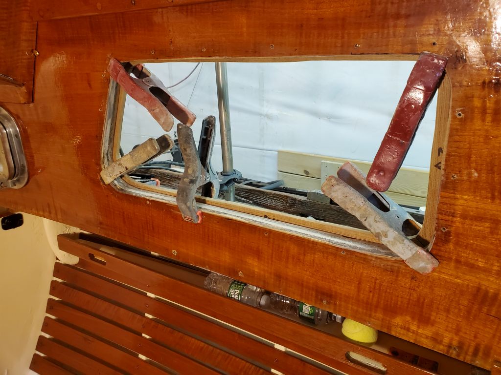
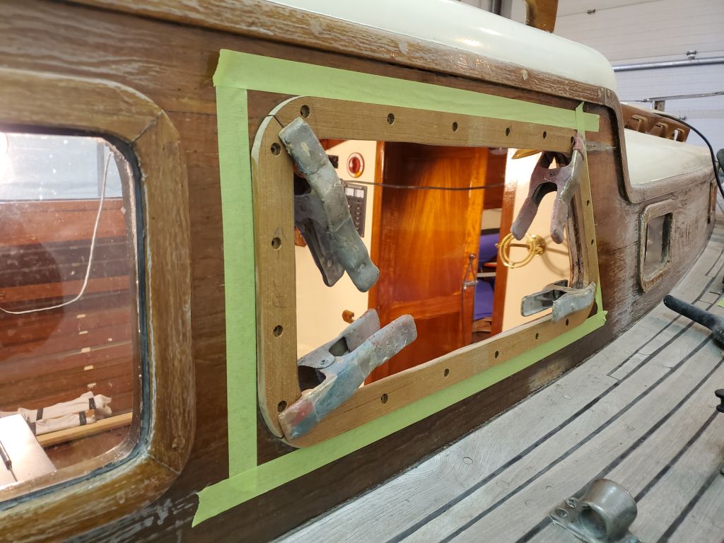
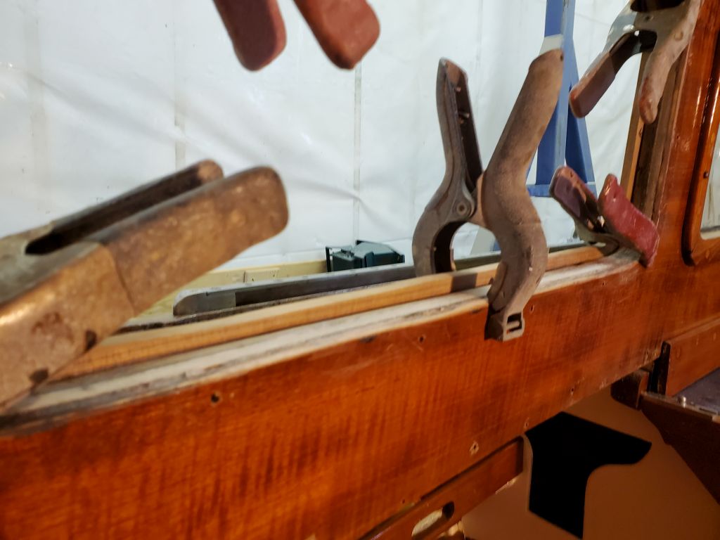
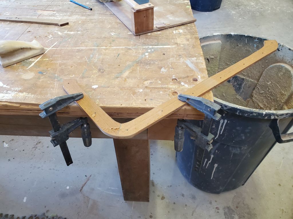
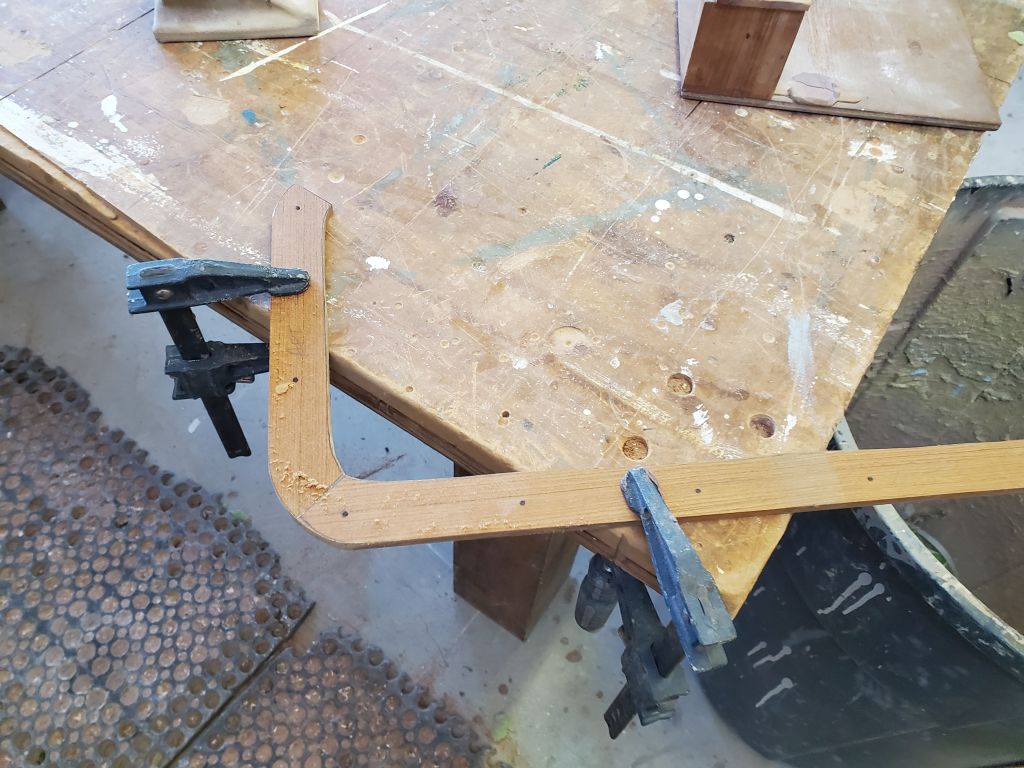
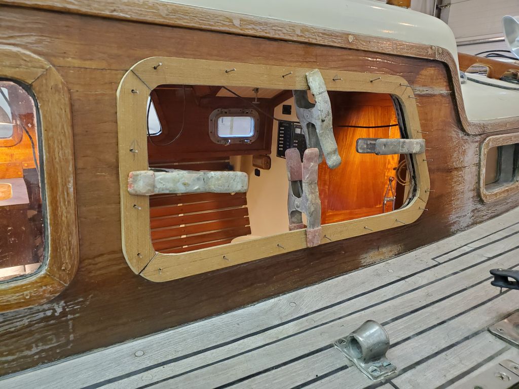
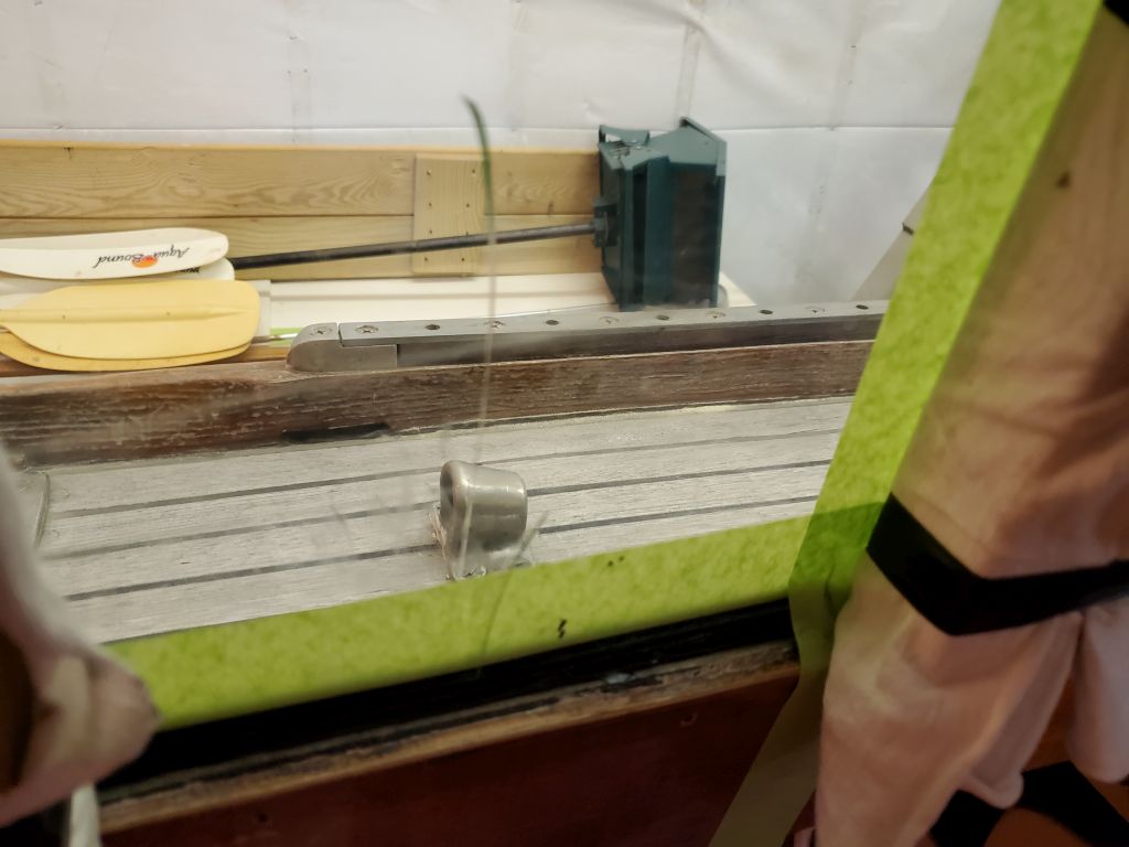
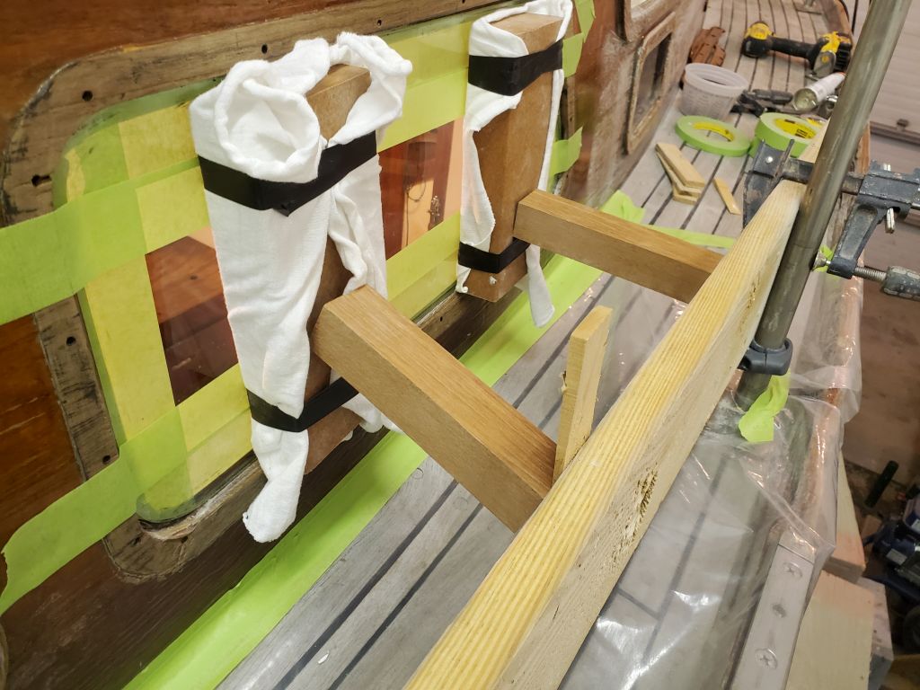
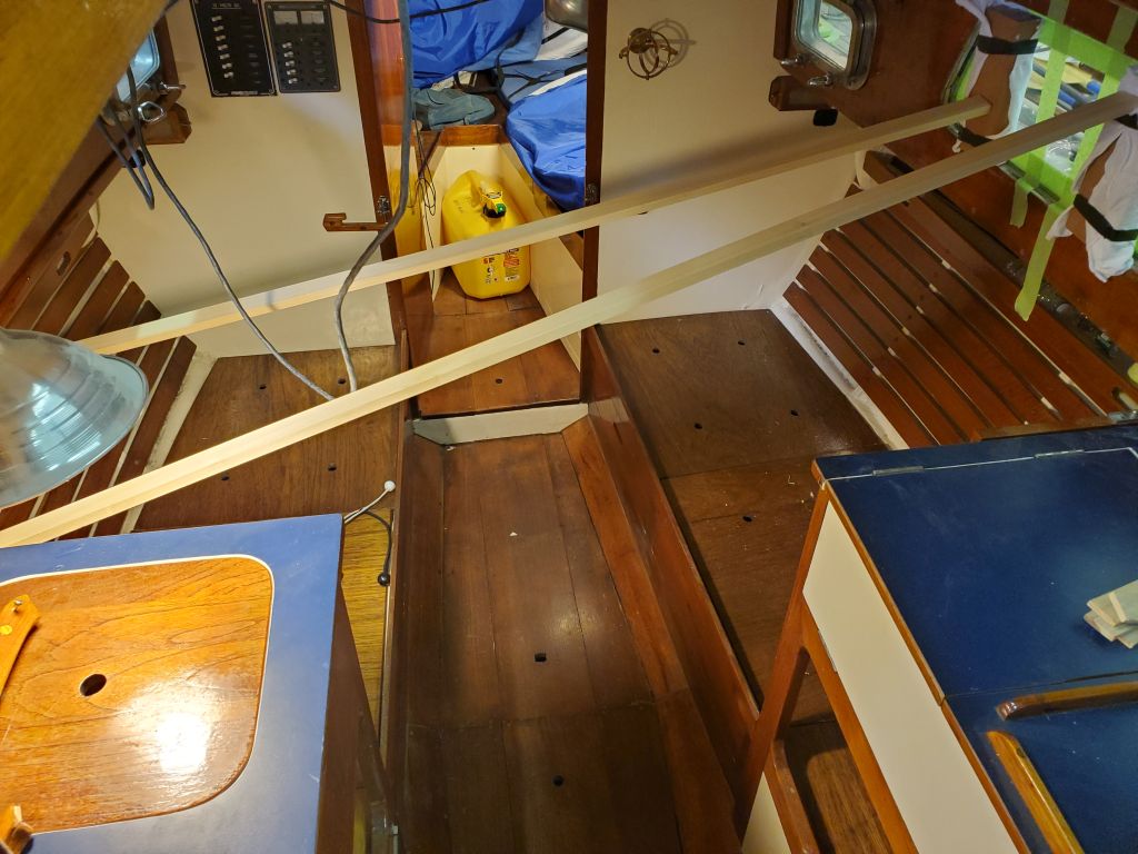
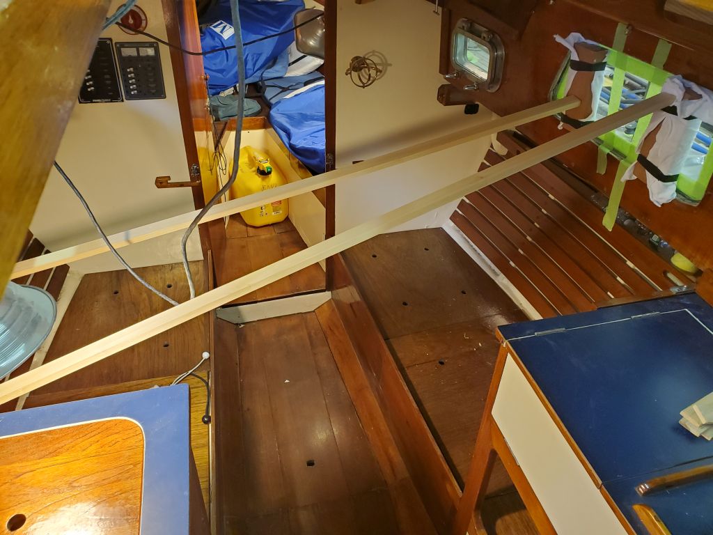
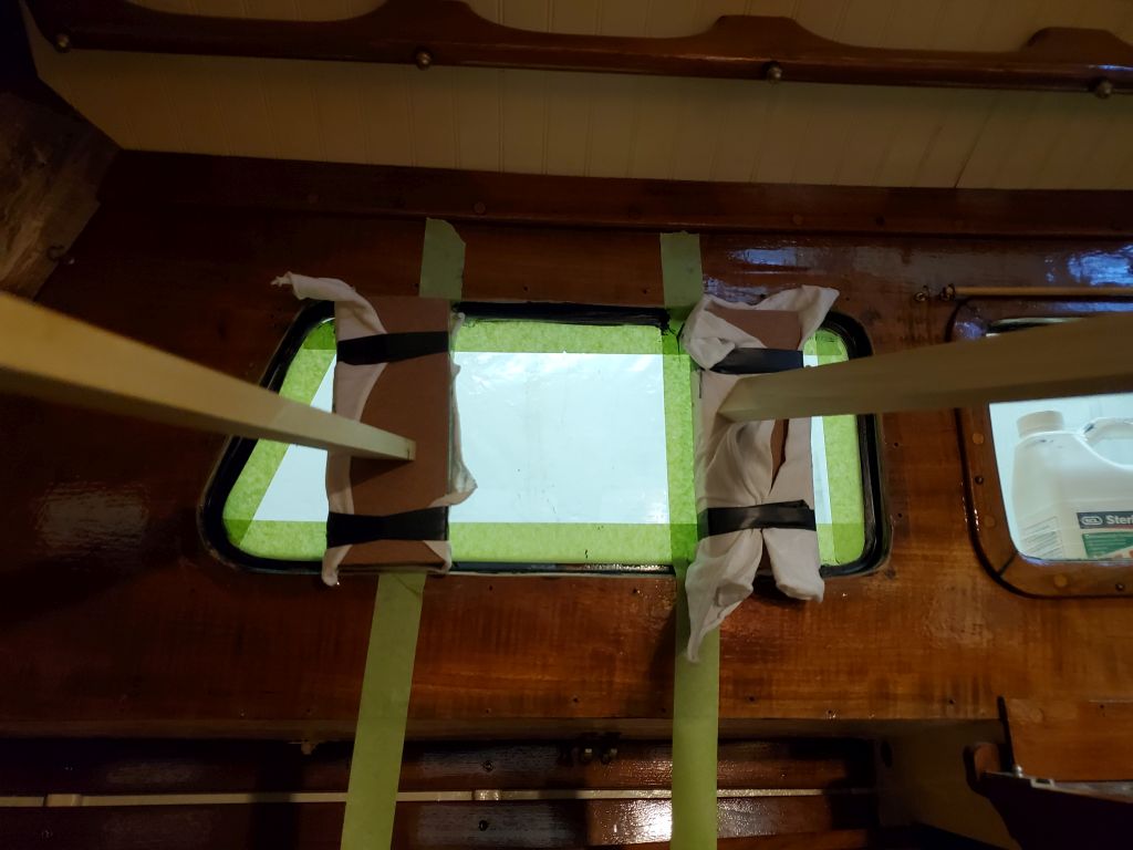
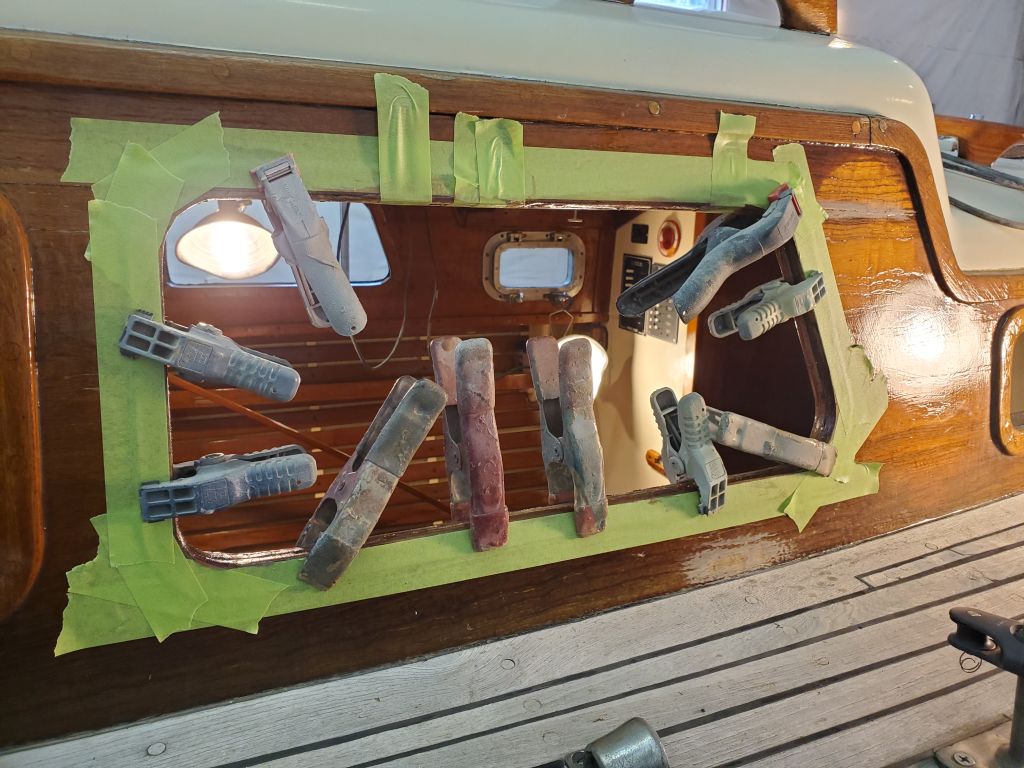
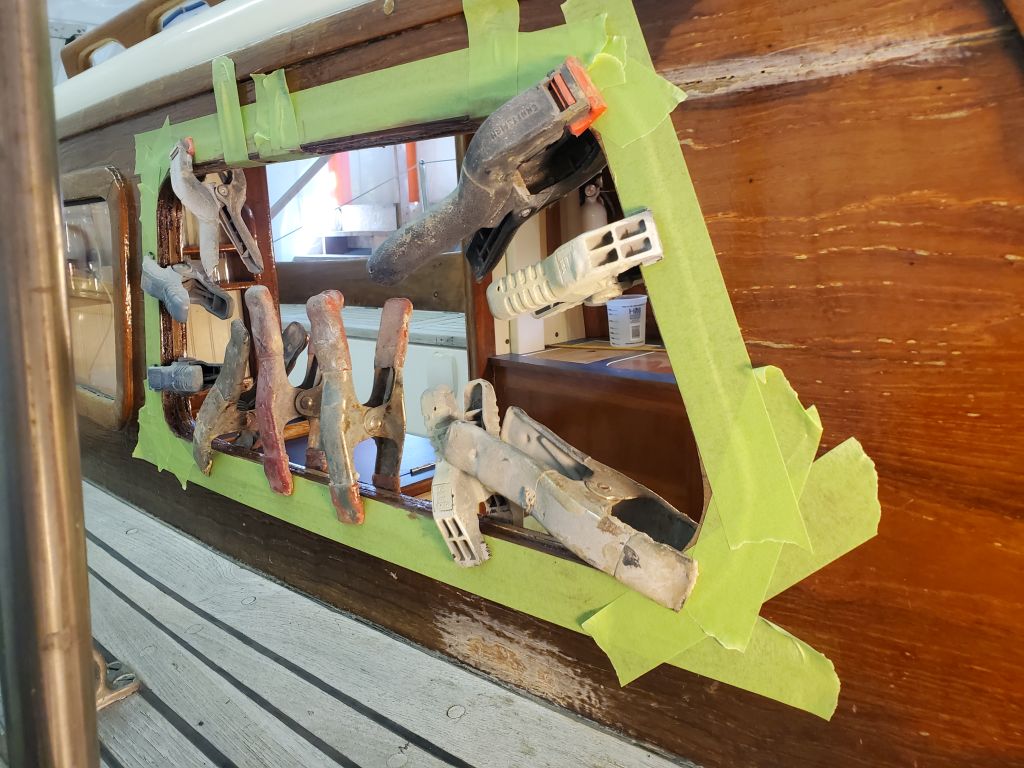
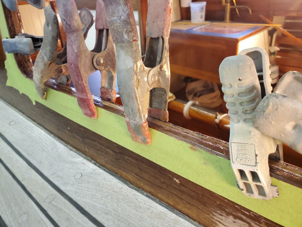
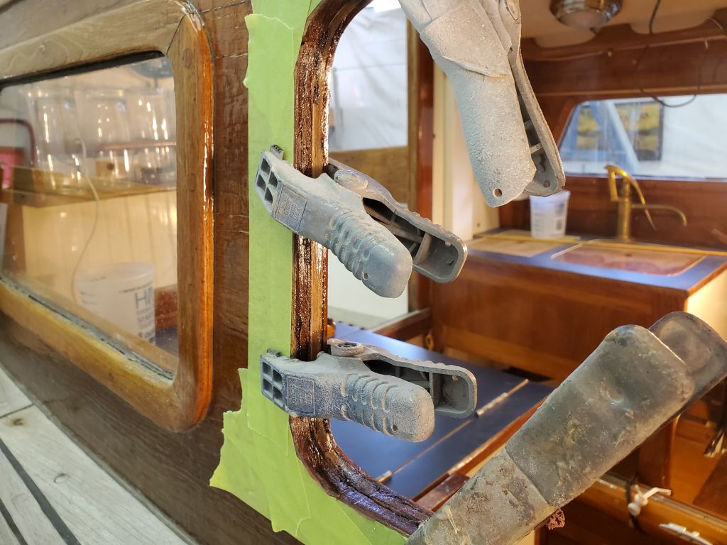
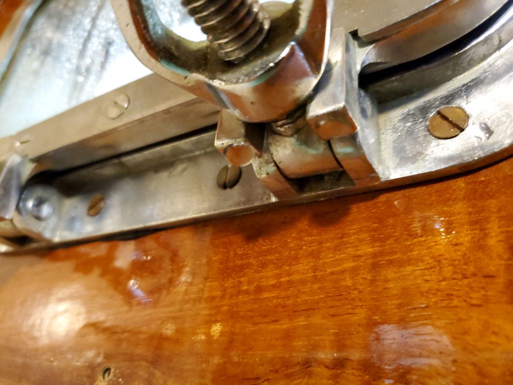
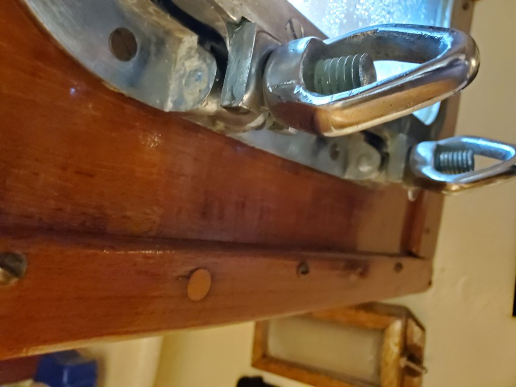
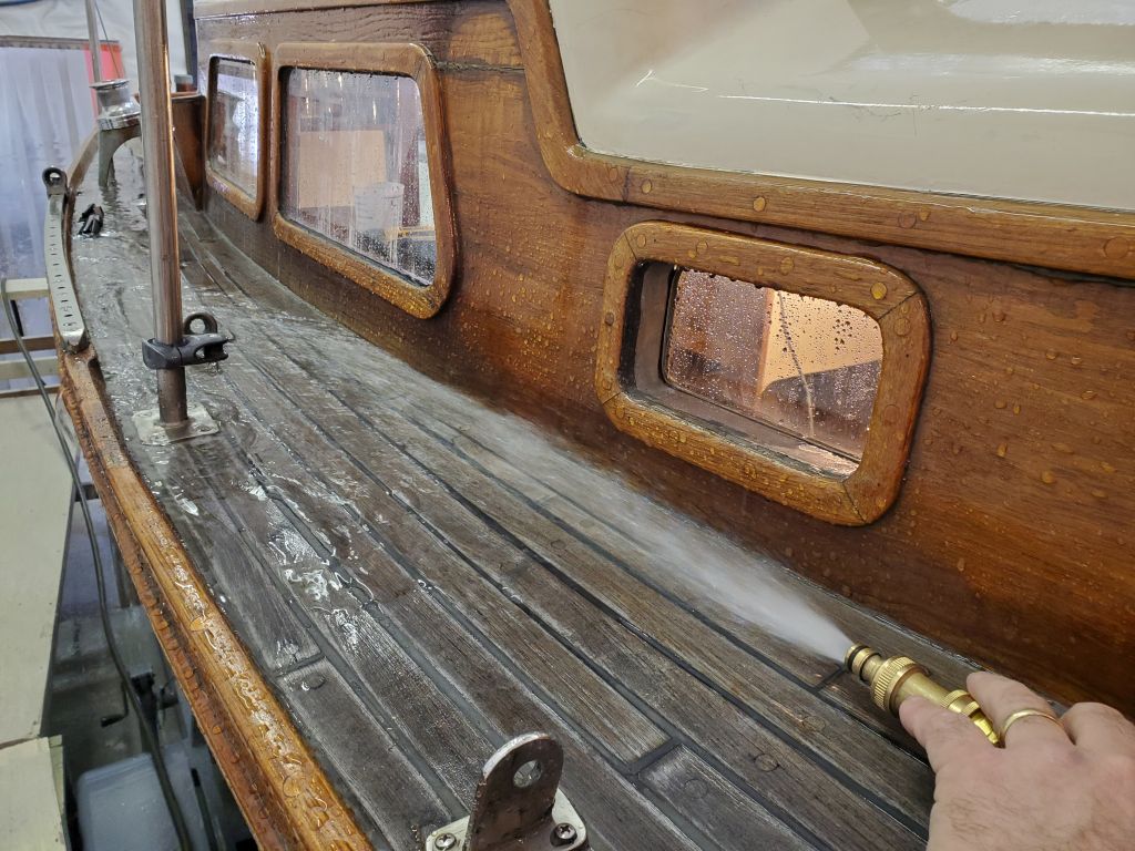
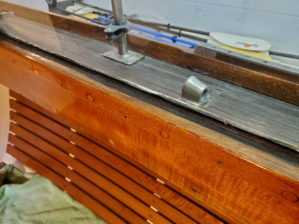
To help hold the glass in place during bedding and installation, I rigged up some blocking to push the glass tightly into the frame from outside.

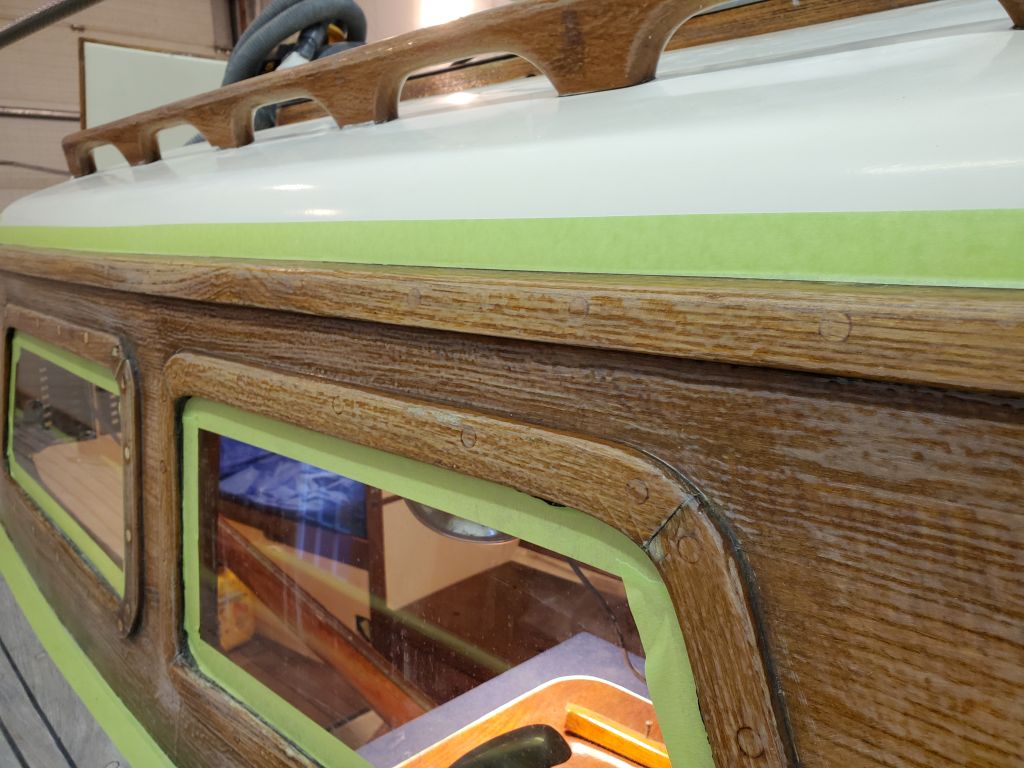
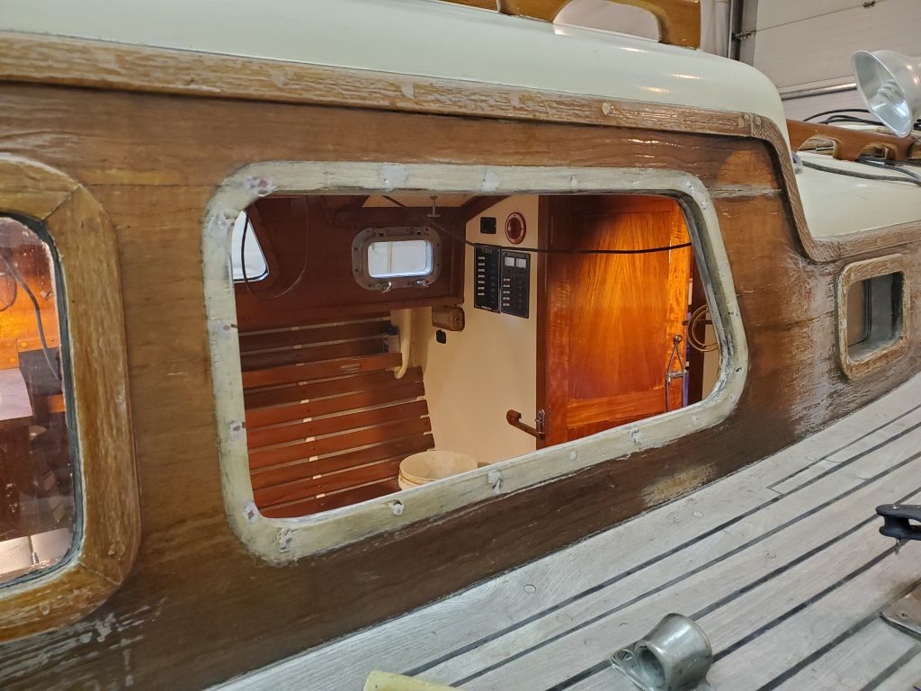
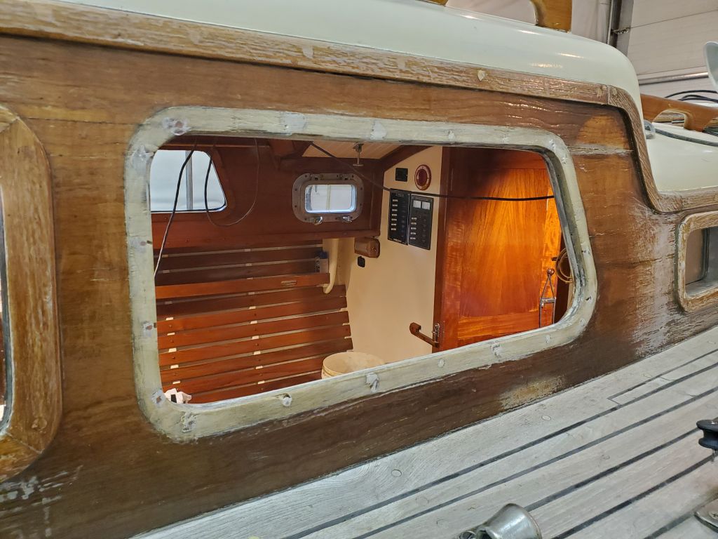
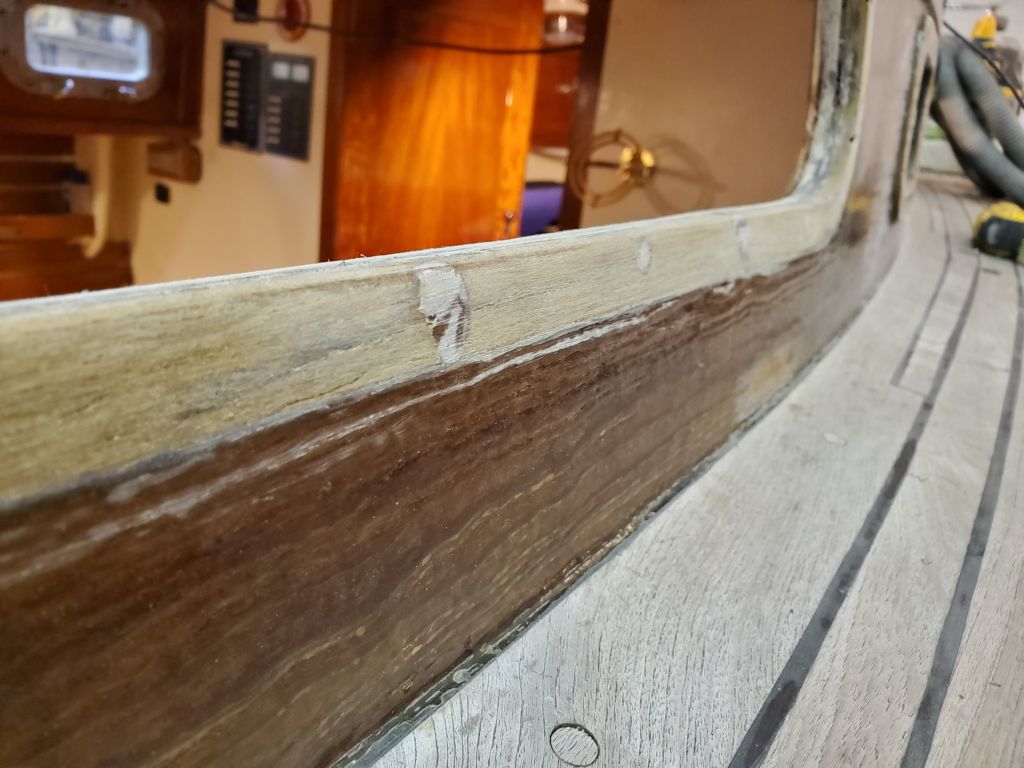
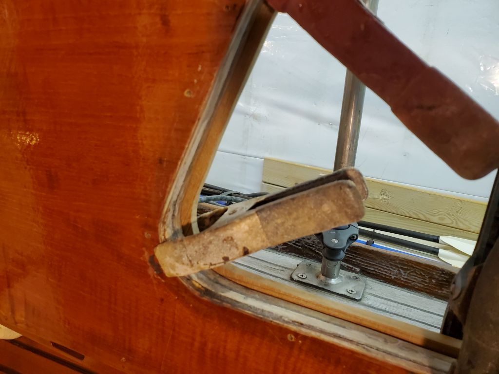
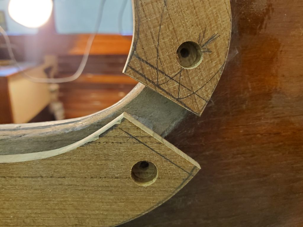
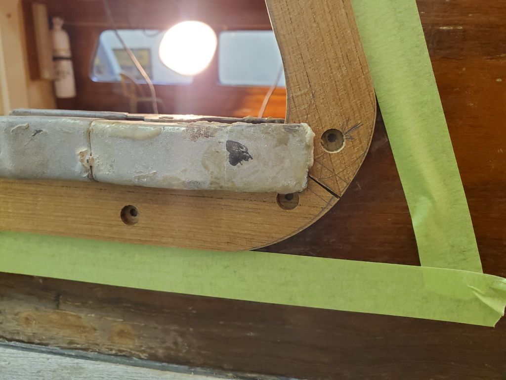
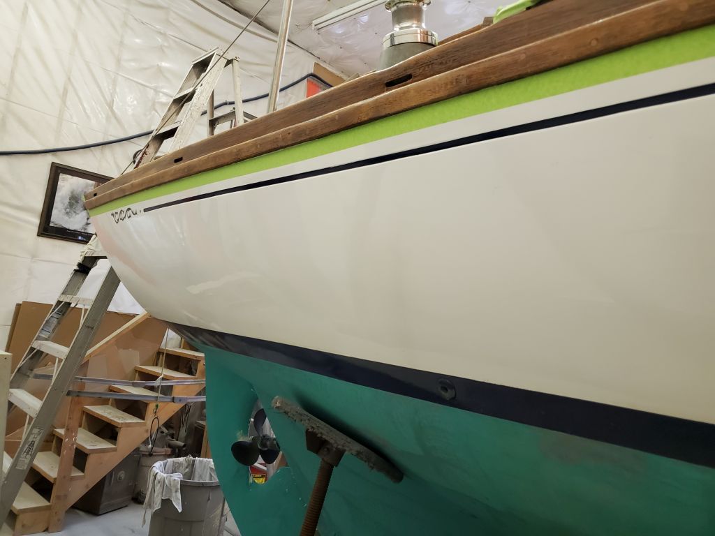
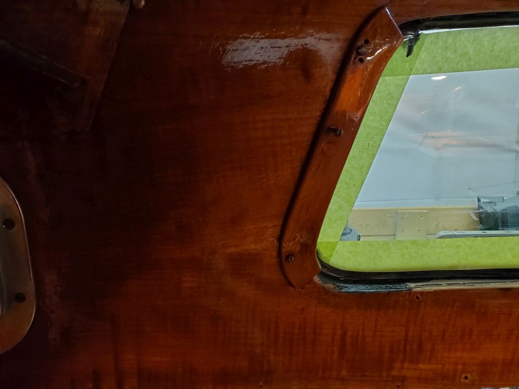
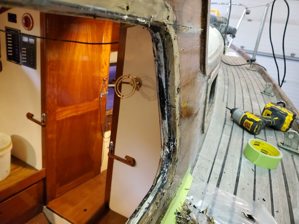
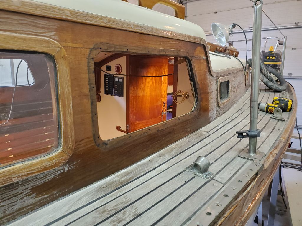
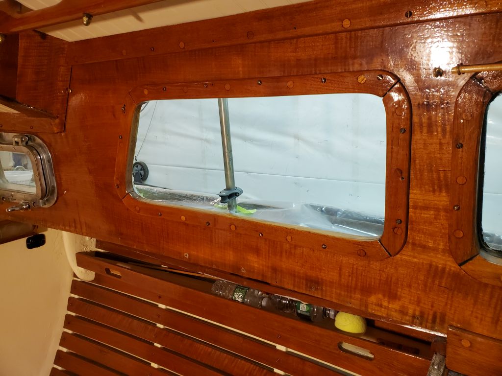
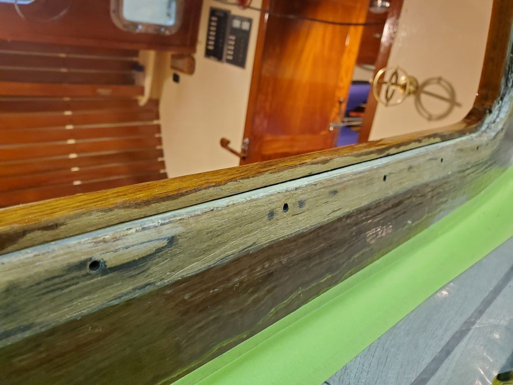
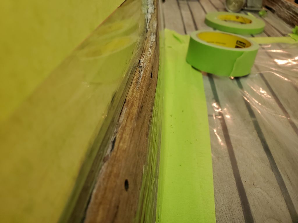
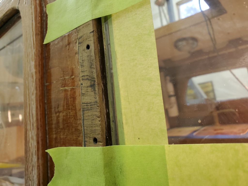
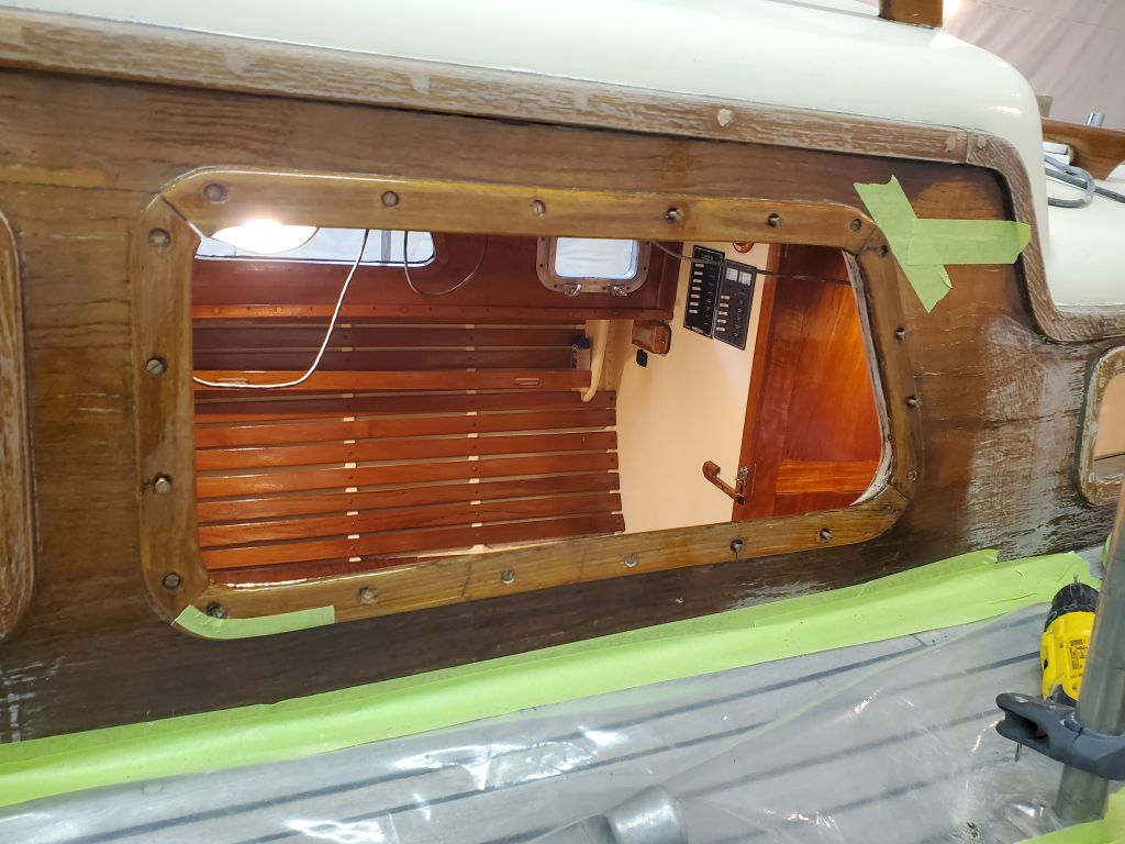
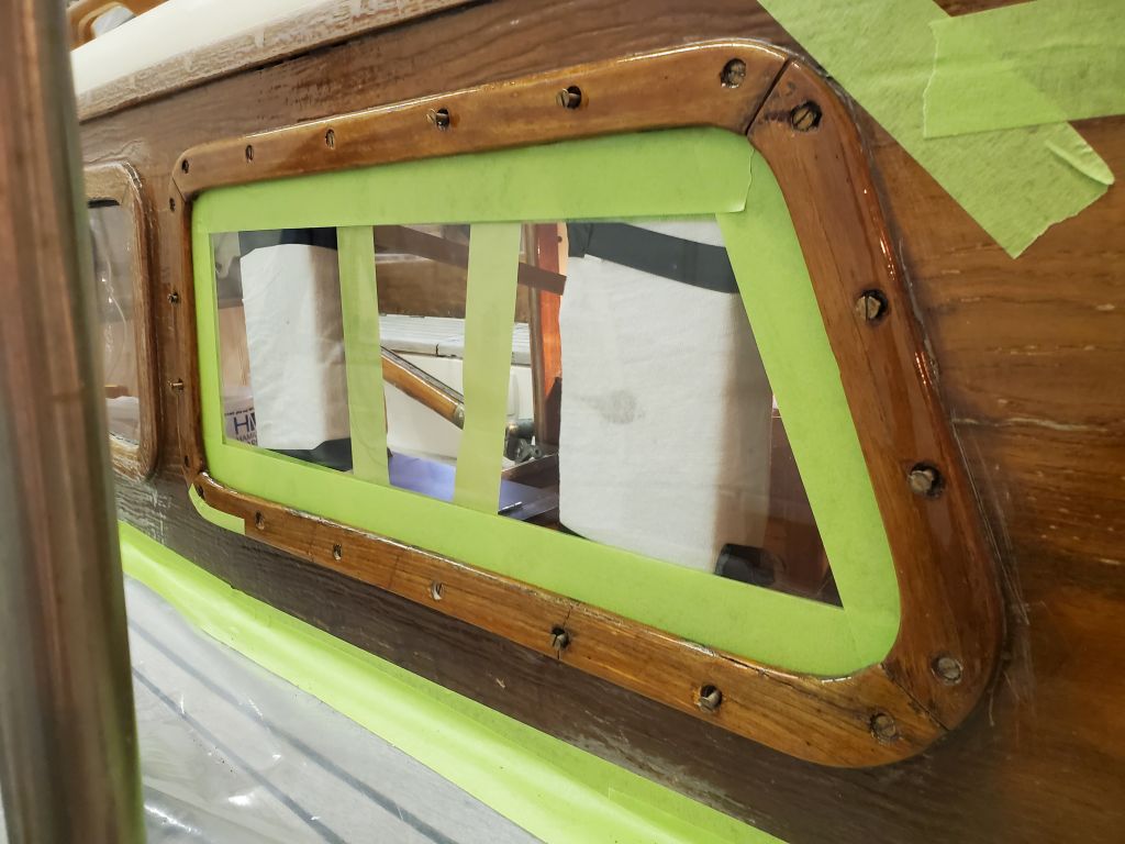
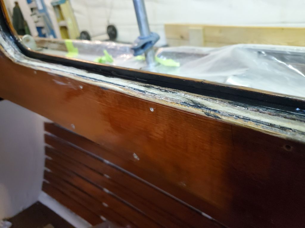
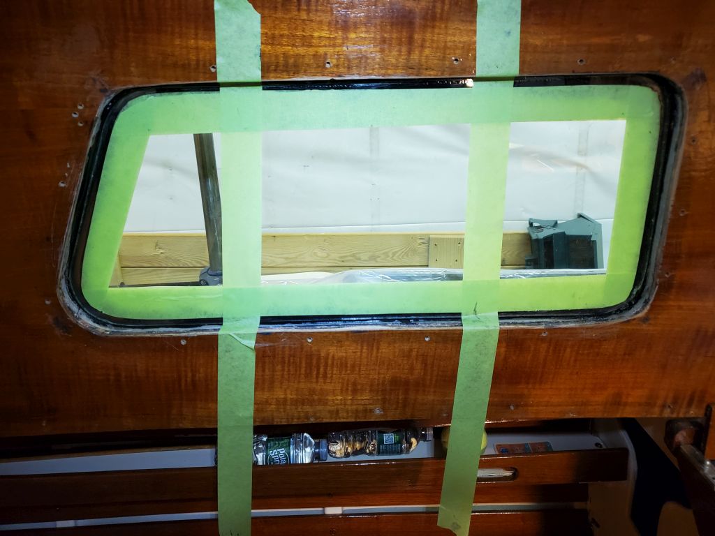
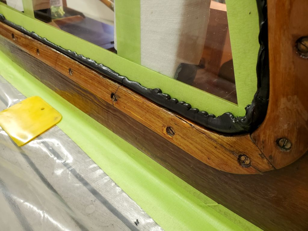
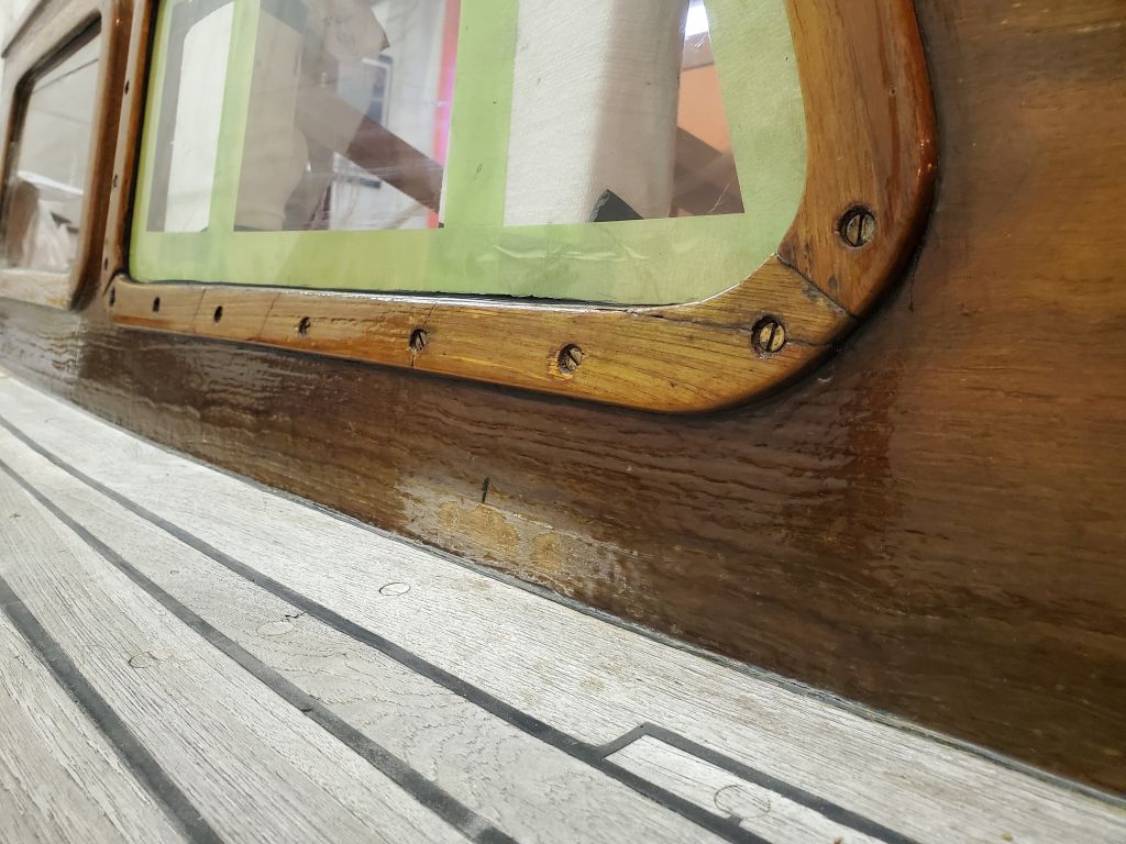
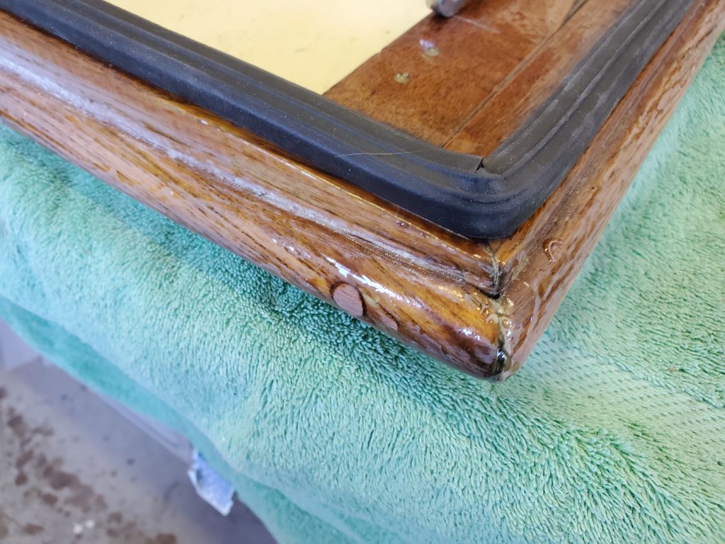
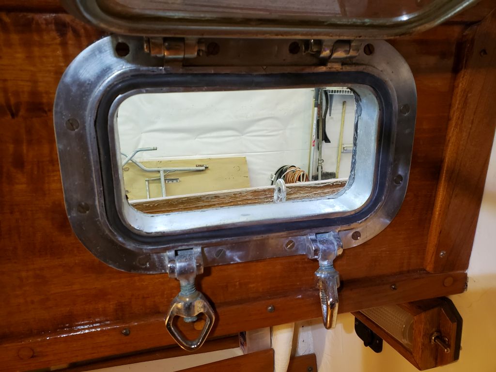
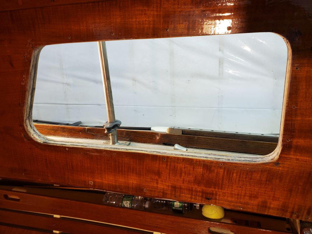
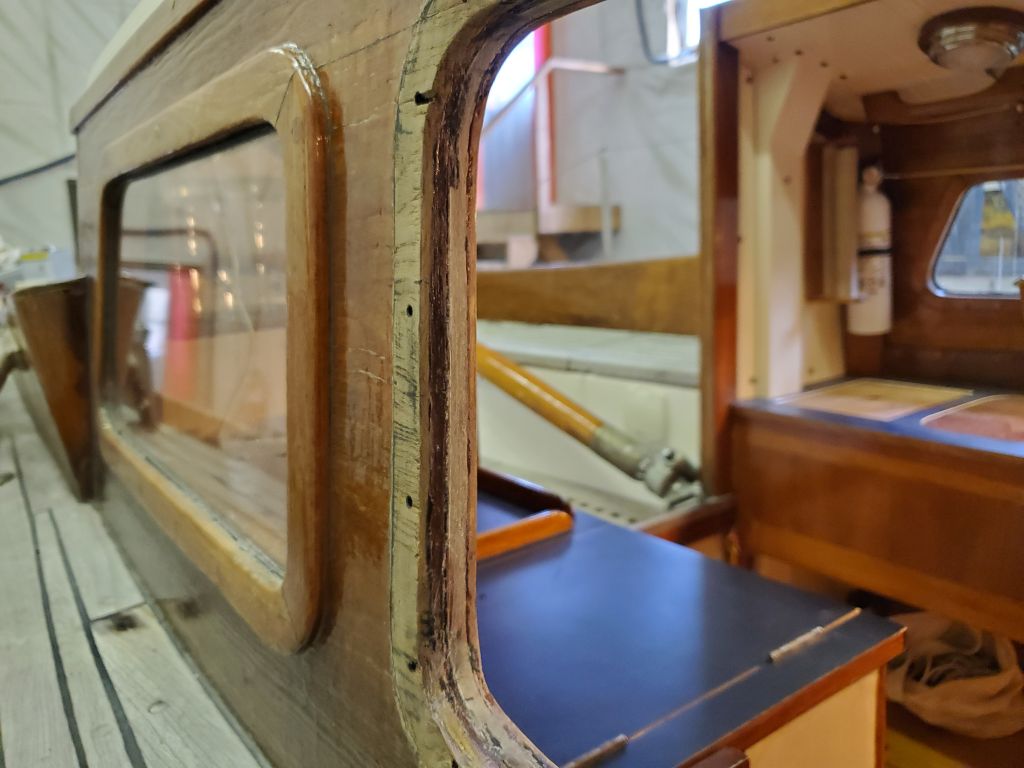
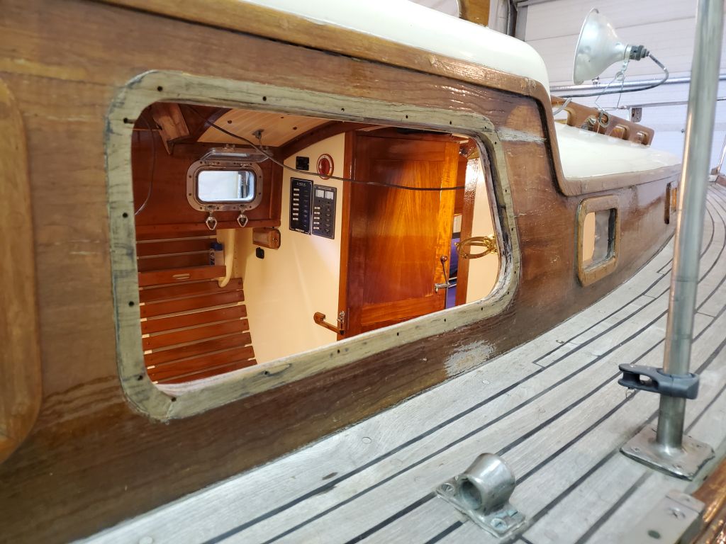
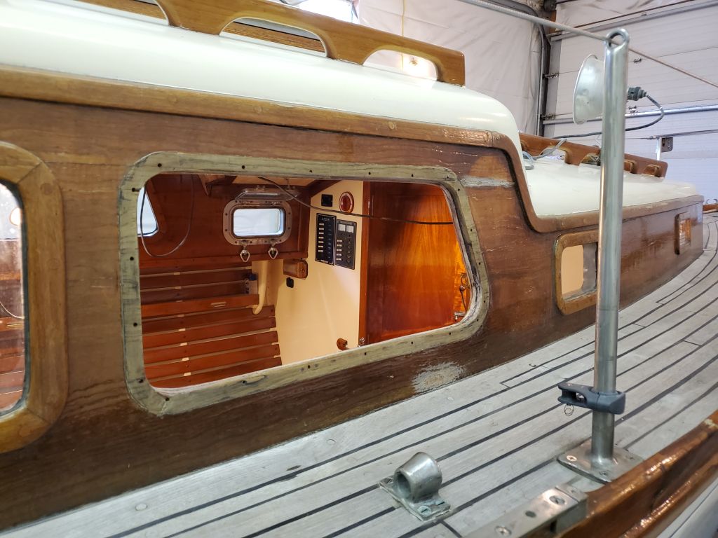
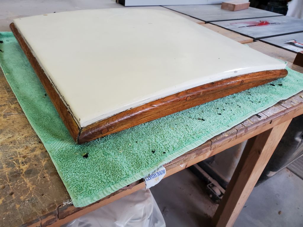
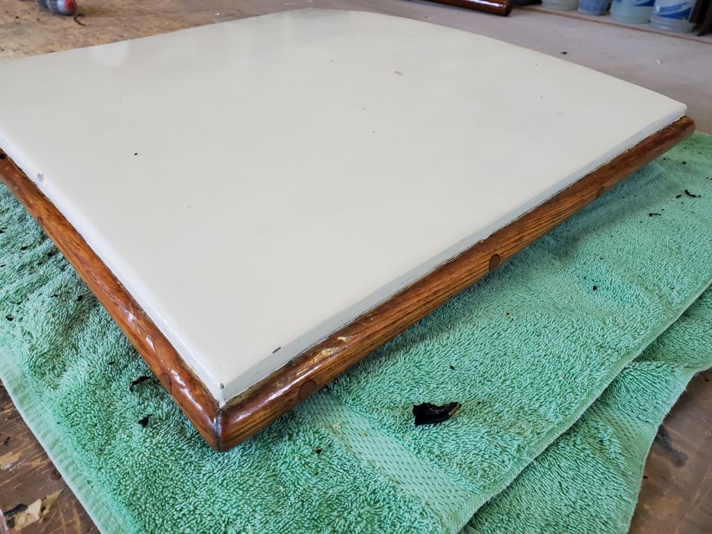
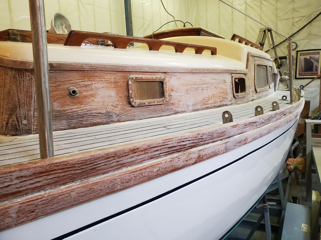
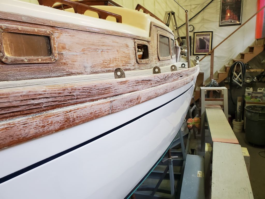
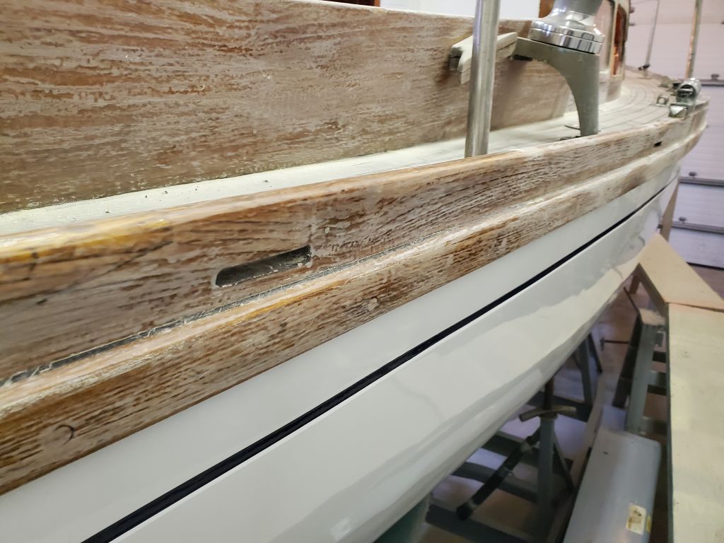
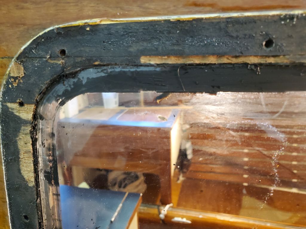
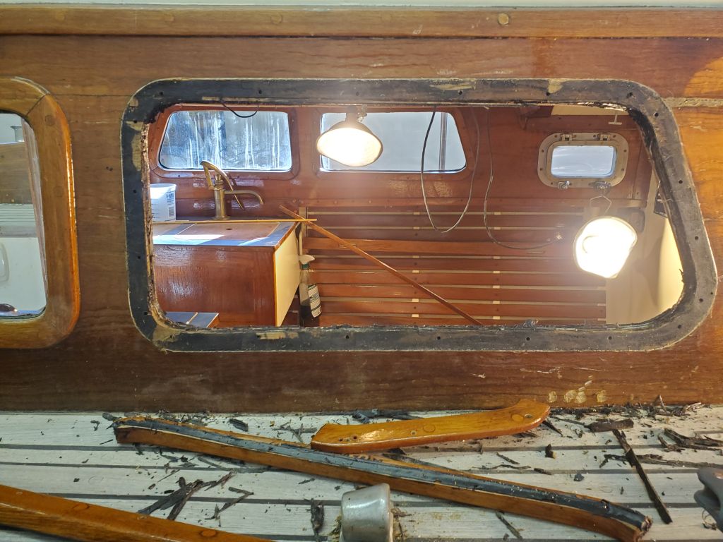
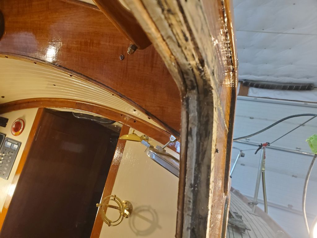
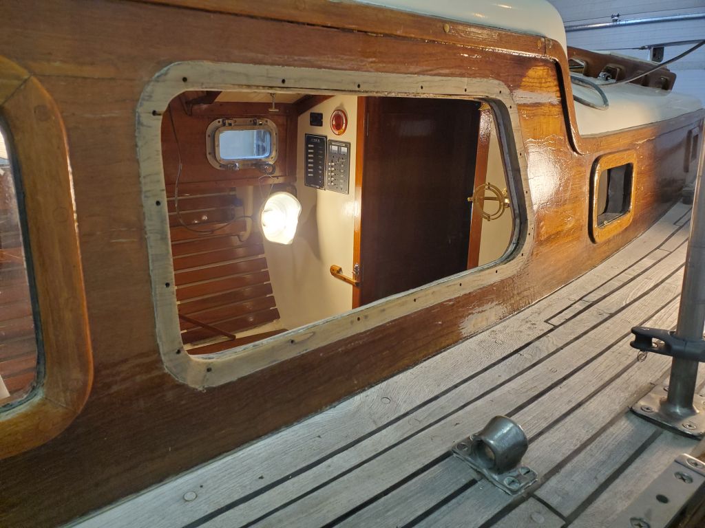
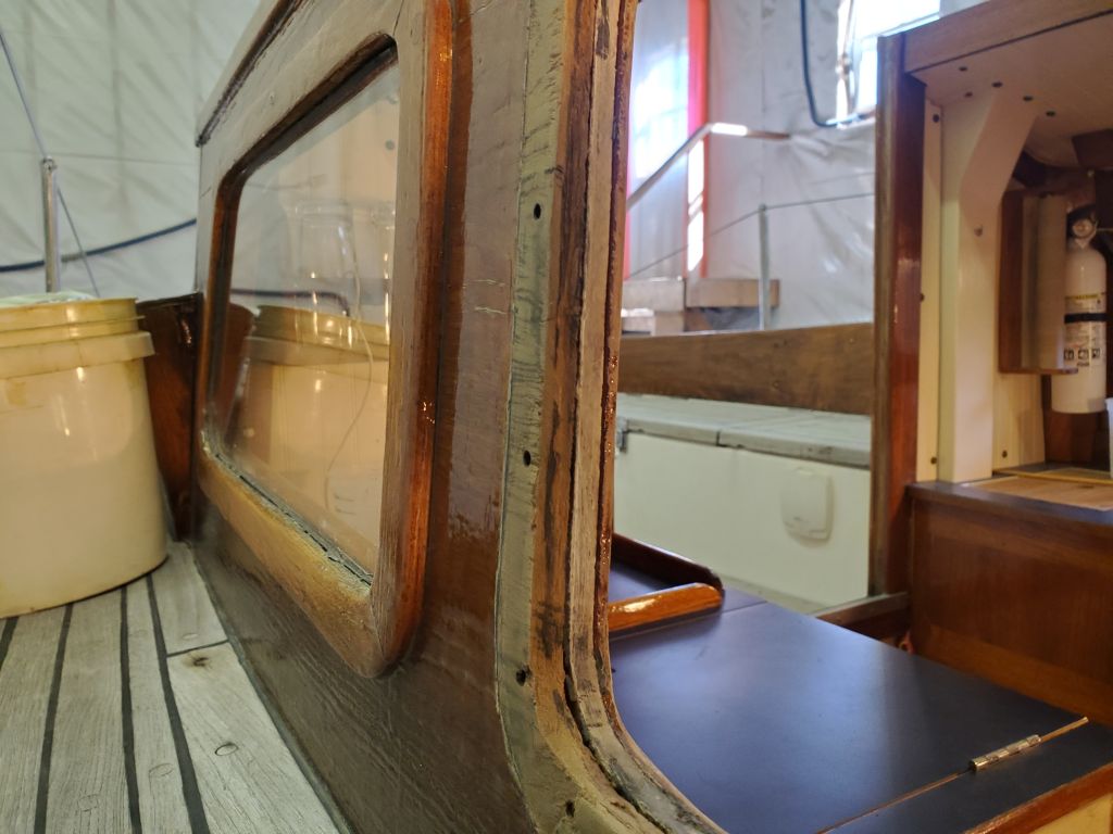
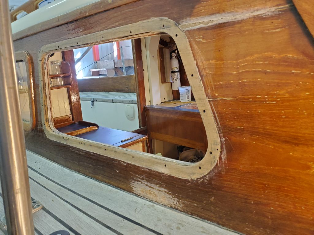
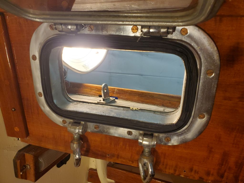
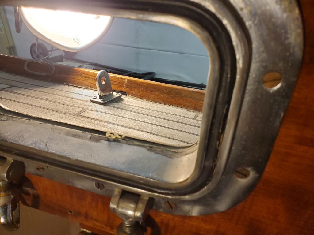
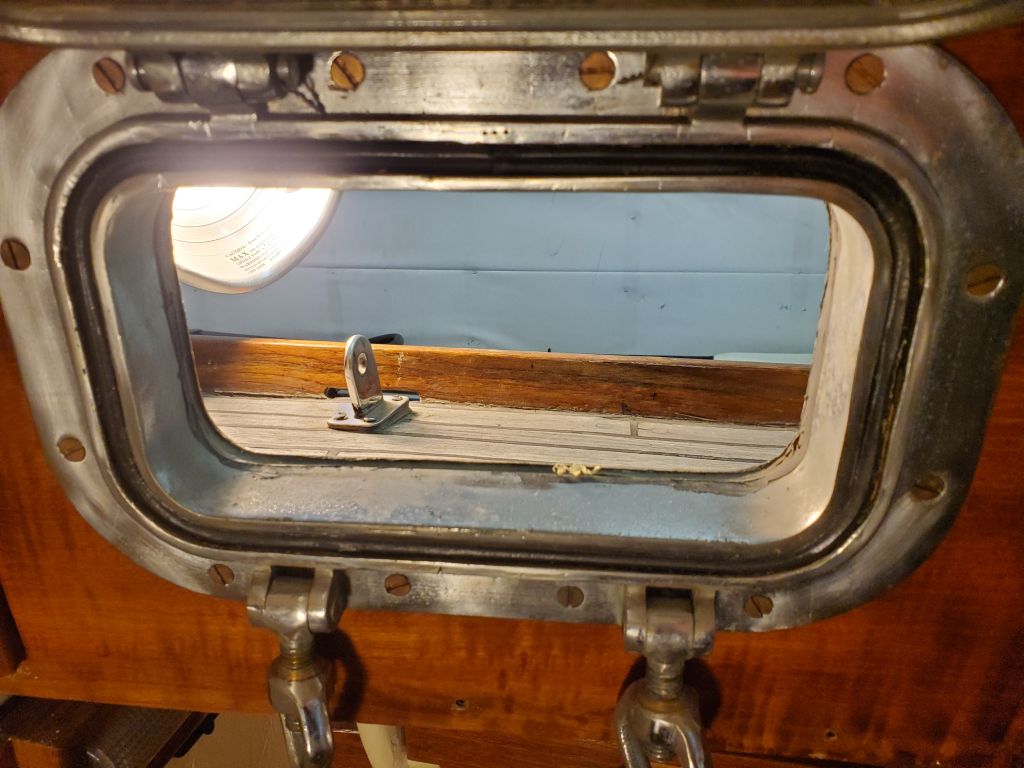
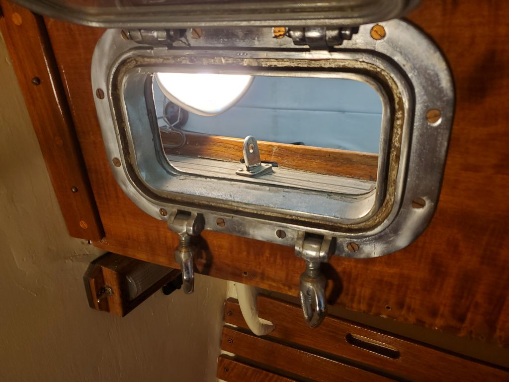
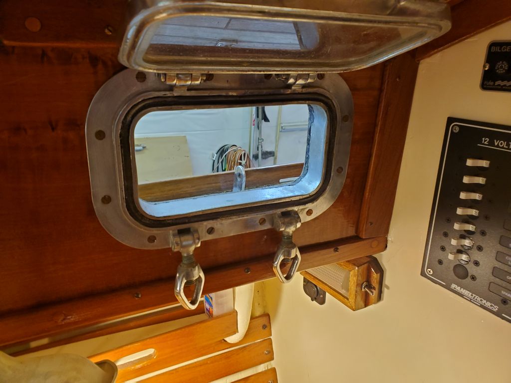
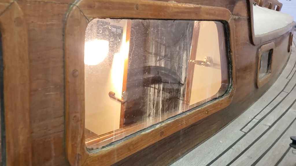
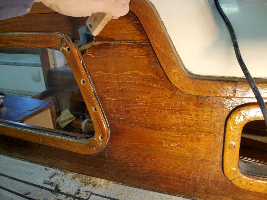
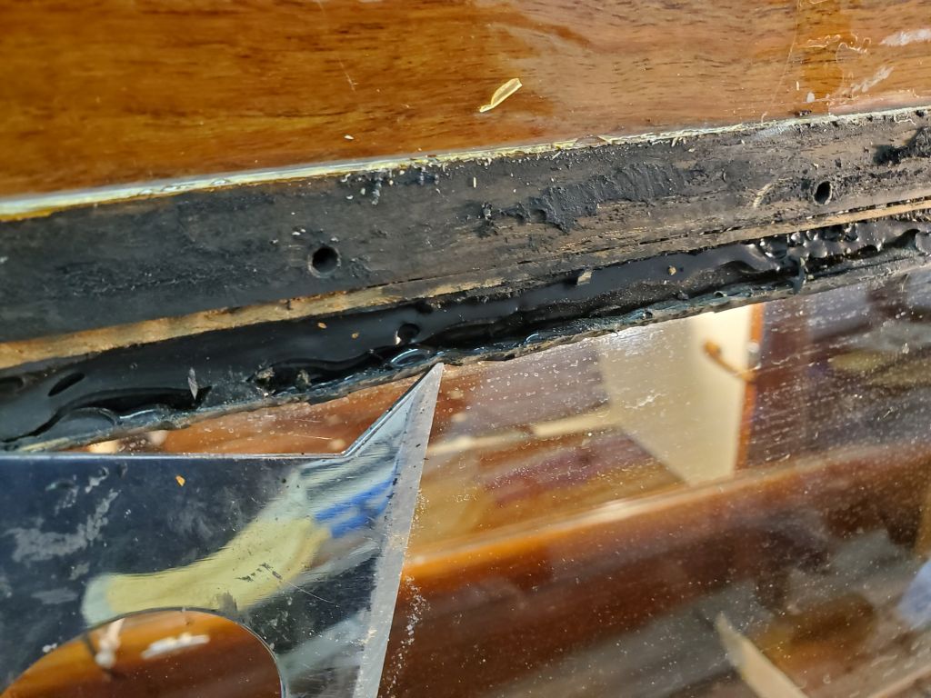
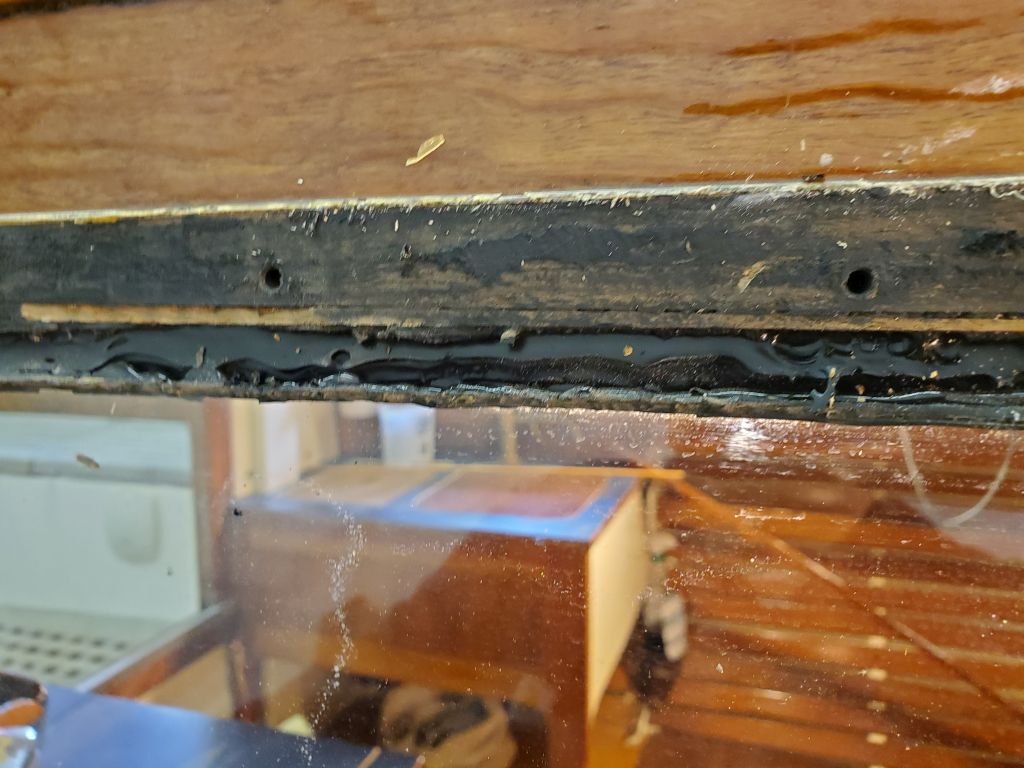
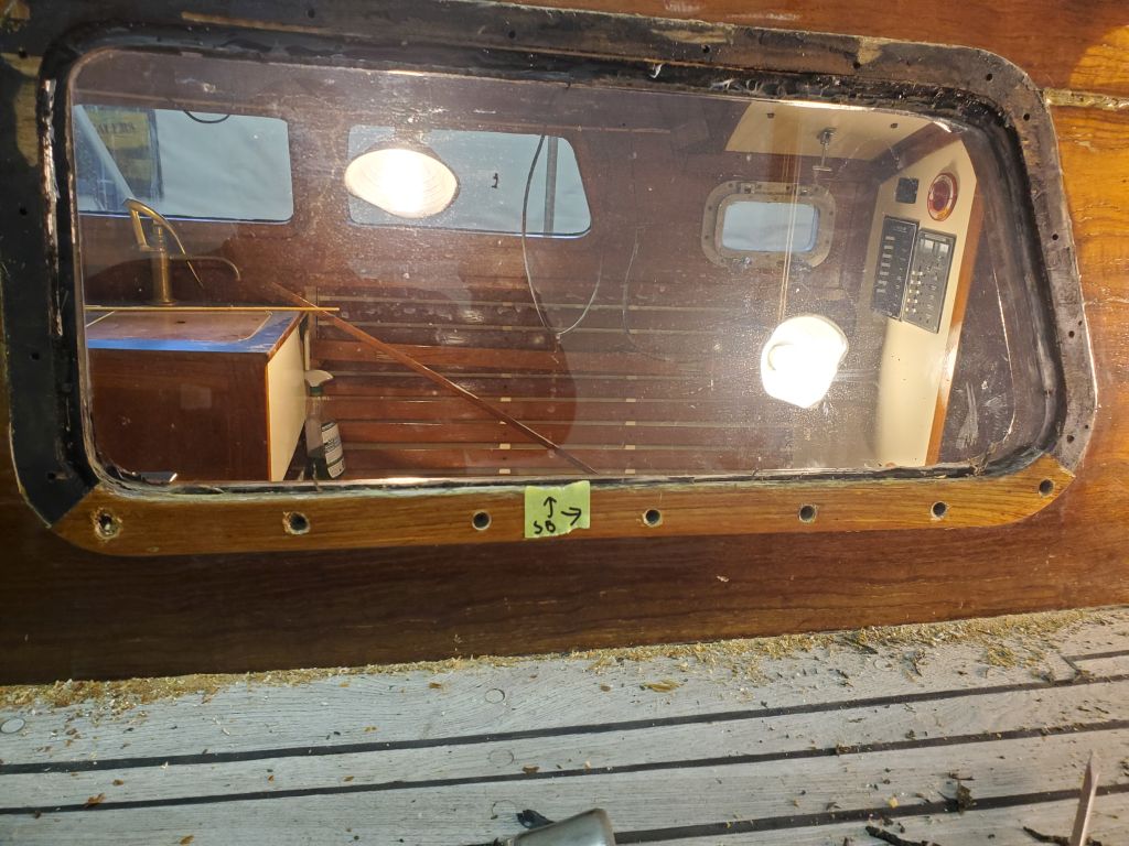
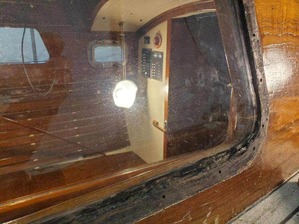
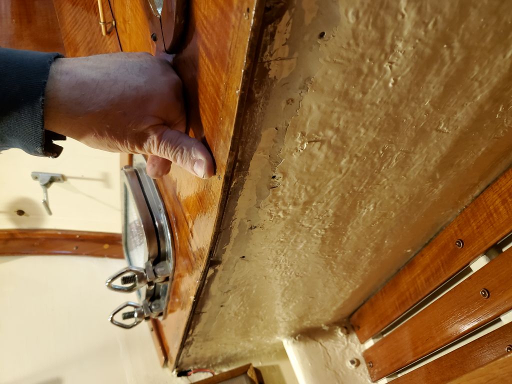
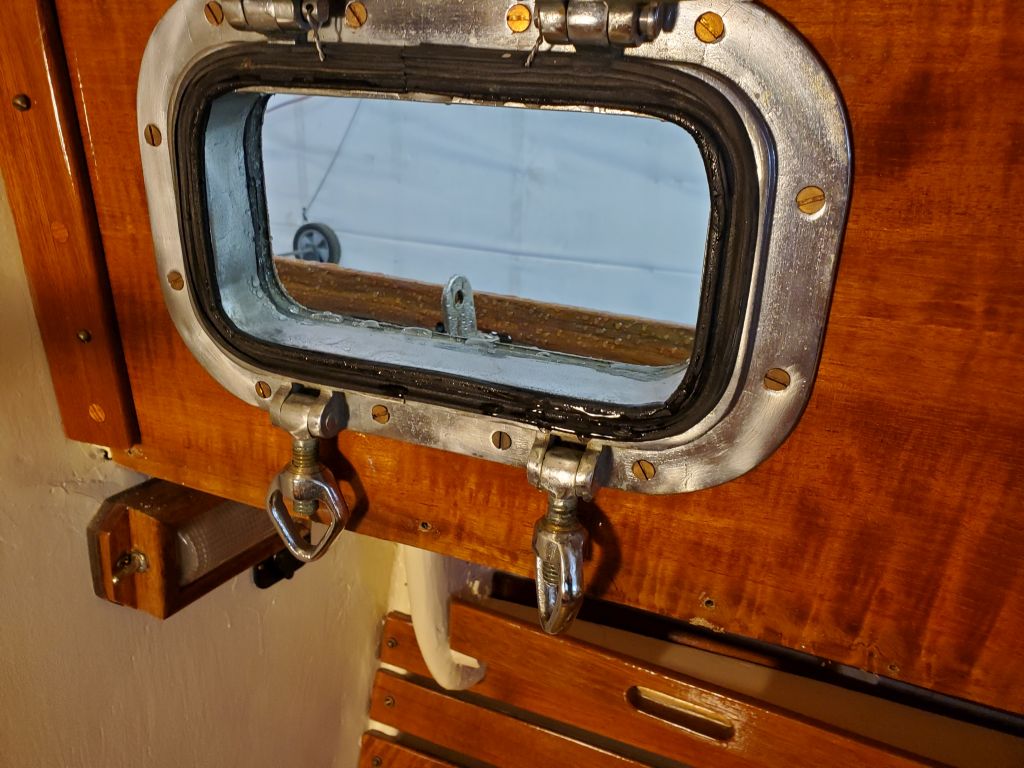
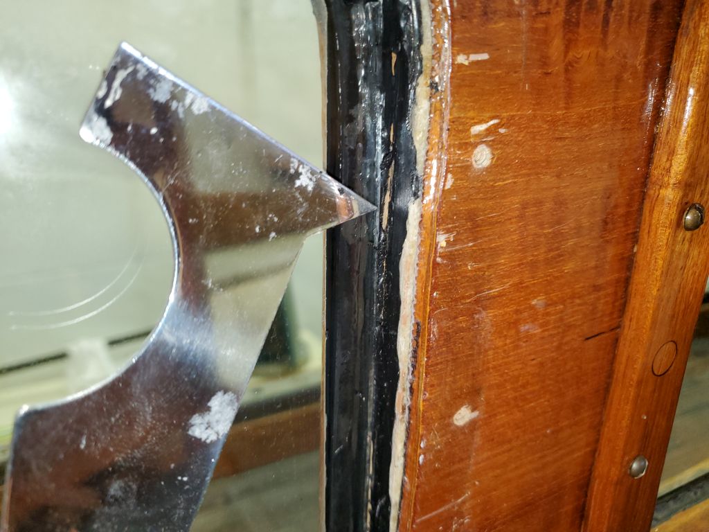
But throughout this, it didn’t look right.  Because of the way I’d ultimately disassembled and removed the deadlight, I’d assumed that reinstallation and bedding would occur in roughly reverse order, and from the outside of the boat, since the interior trim featured a lip that extended into the opening behind the glass.  But on the outside, this left a wide 1/4″ or greater space between the lens face and the cabin side, and since the exterior trim was flat, this meant that the trim would never bear against the lens and make sealing difficult.

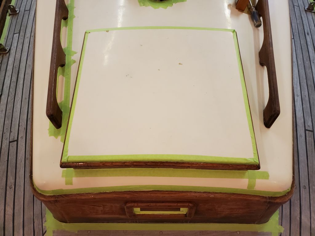
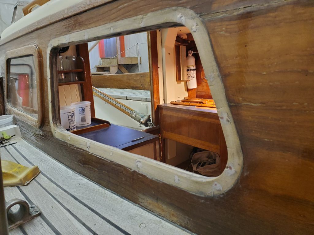
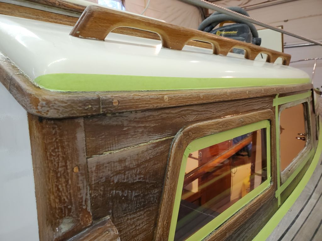
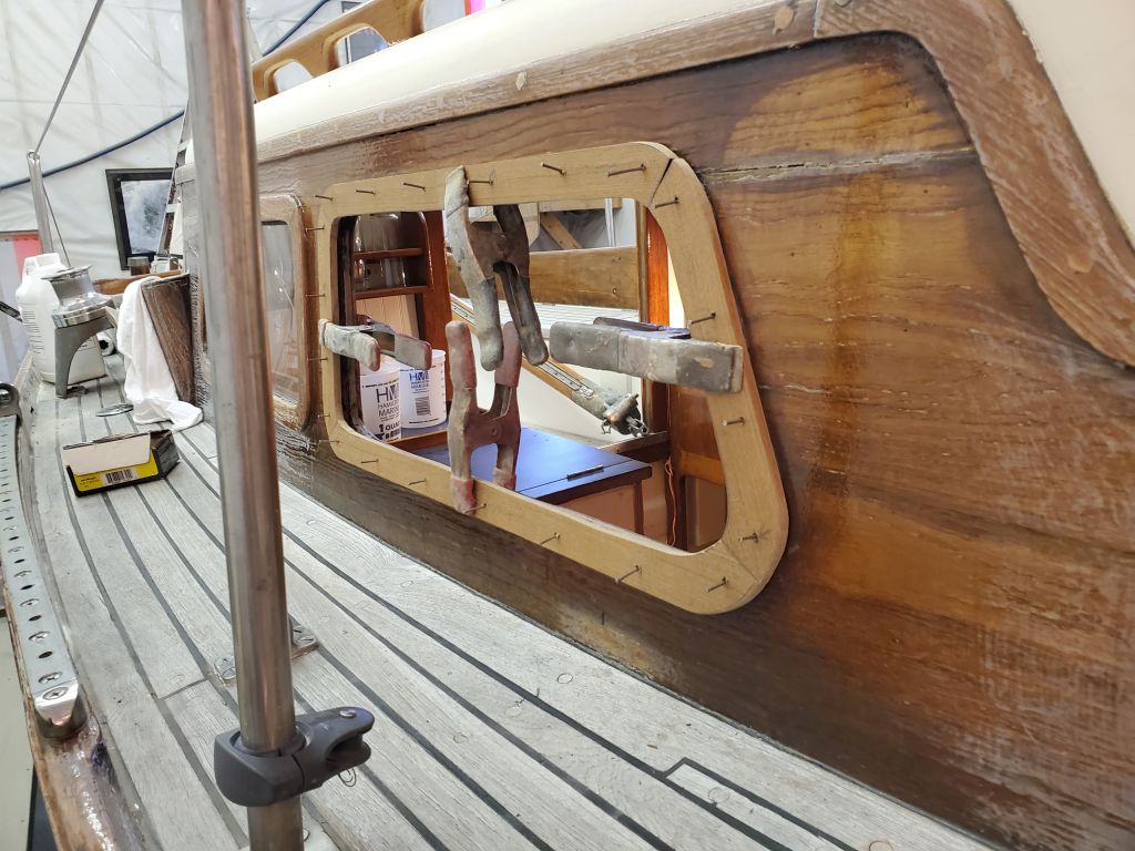
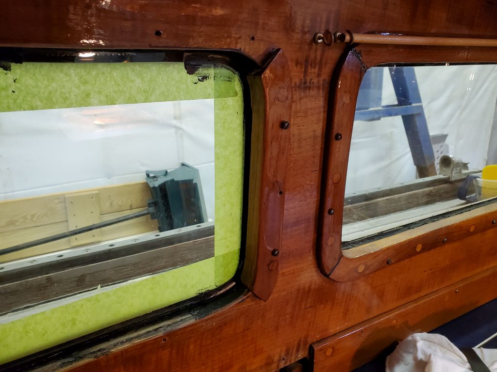
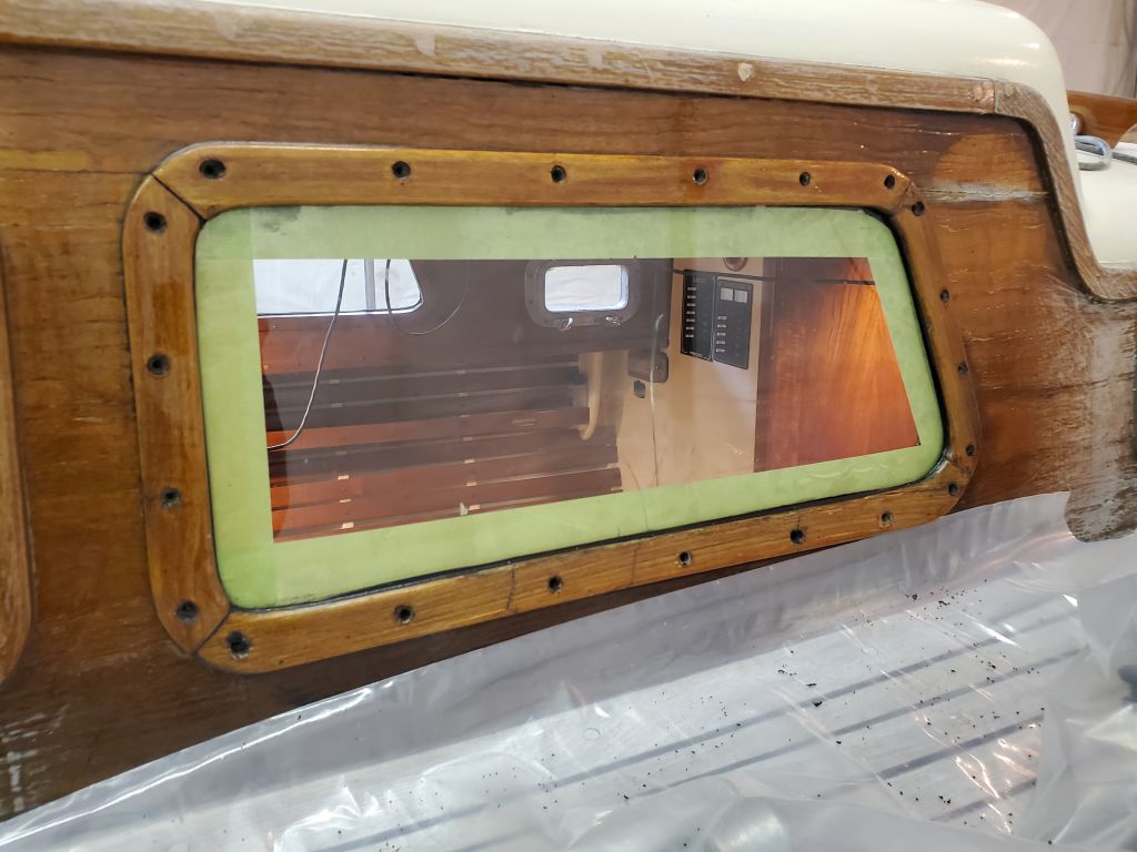
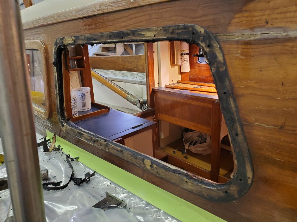
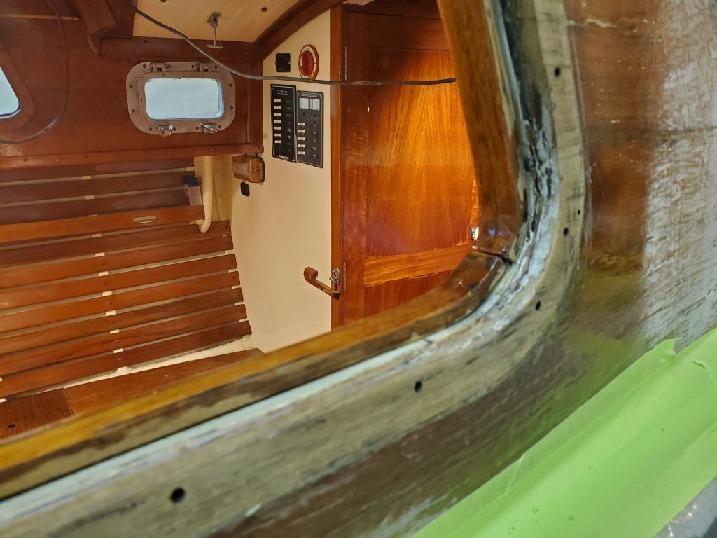
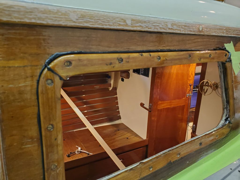
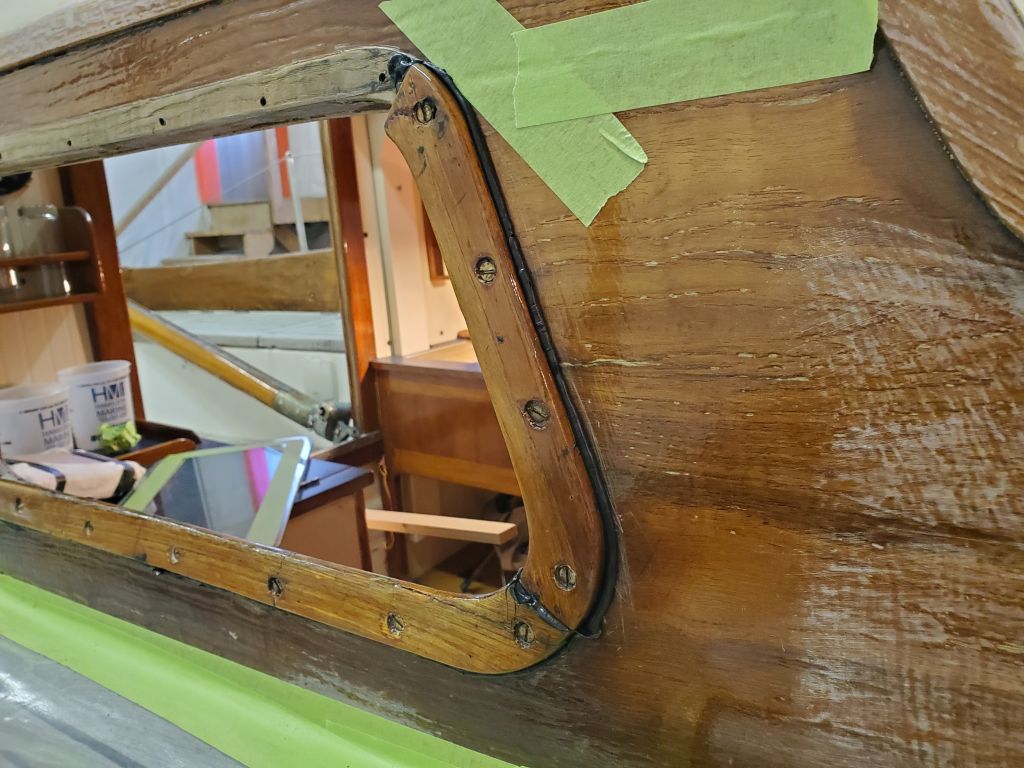
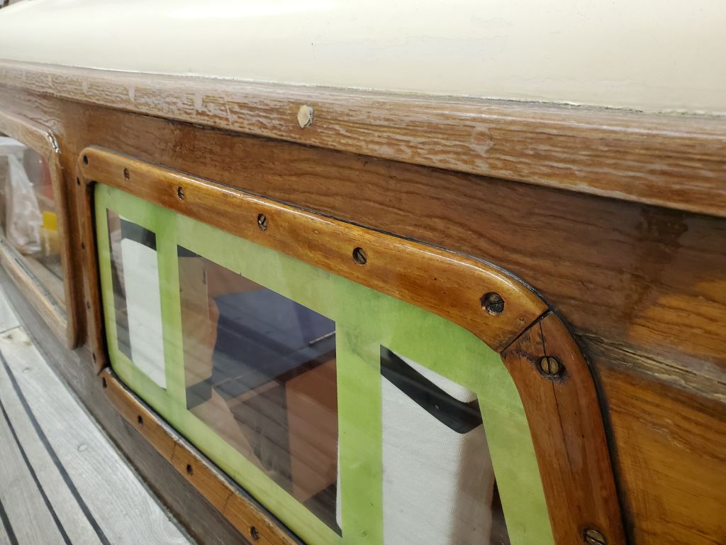
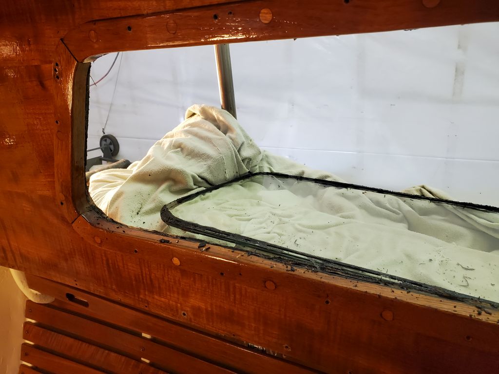
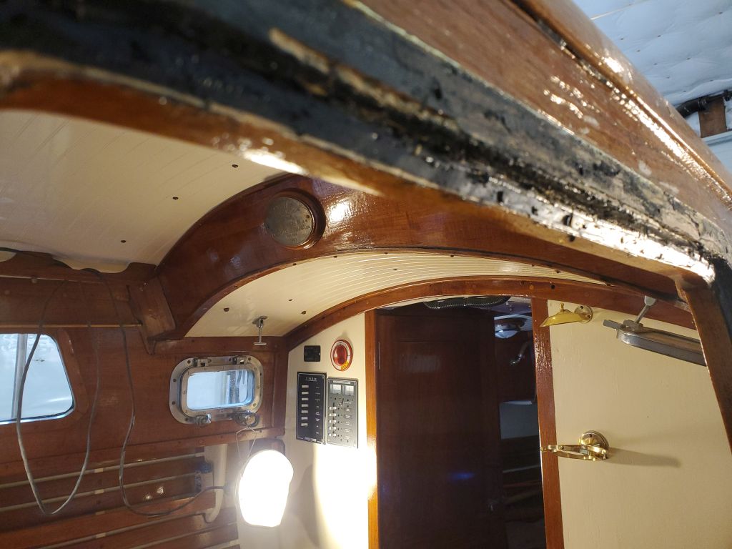
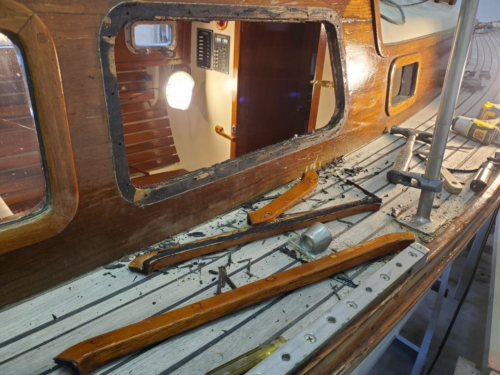
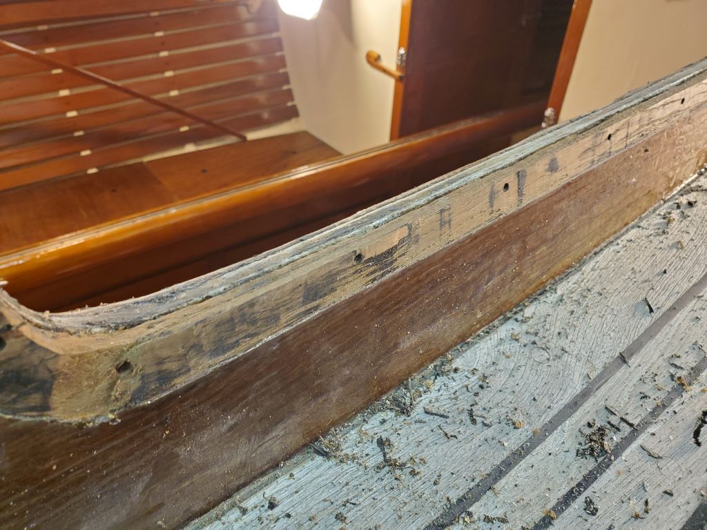
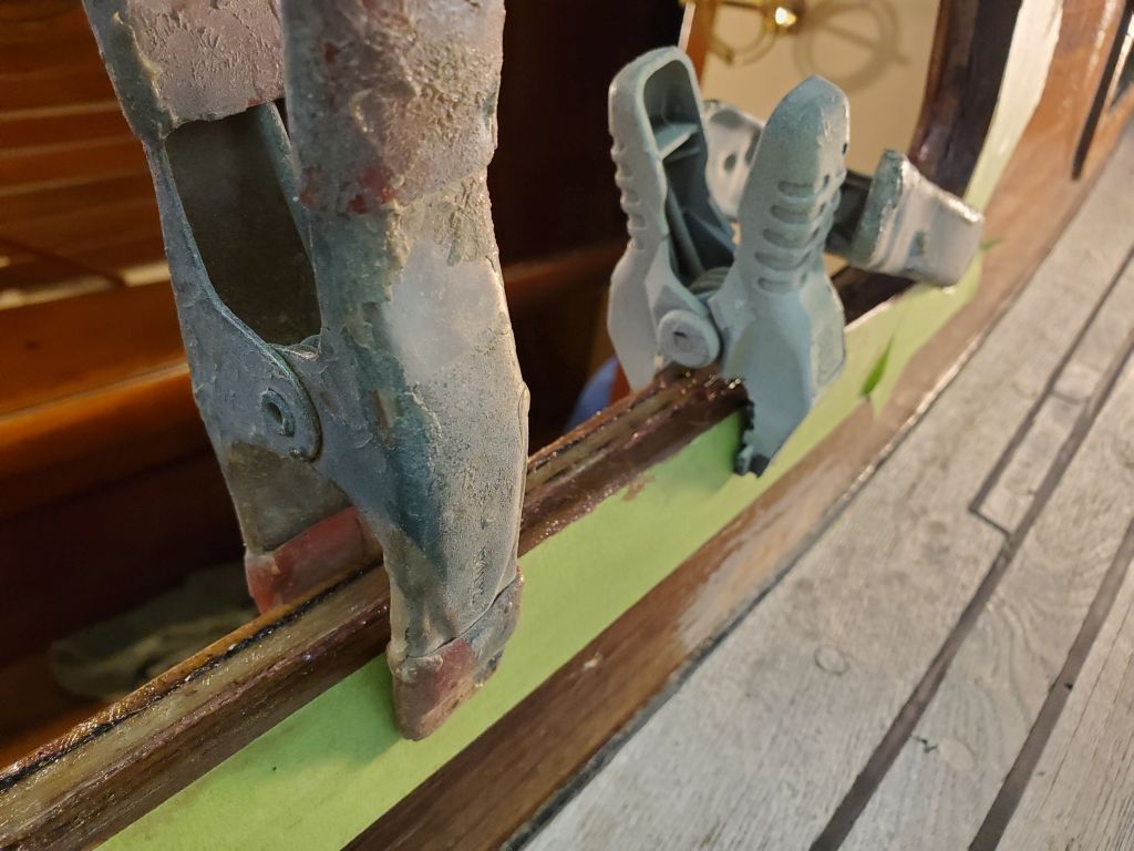
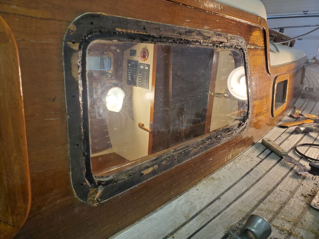
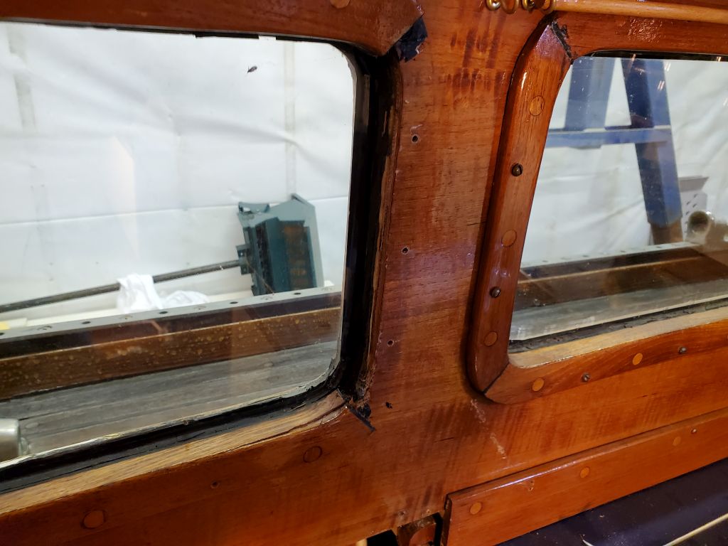
There was just no way the installation was going to work this way, and after looking over the remaining three deadlights, it seemed clear that what I had to do was basically the opposite of what I’d started:  I’d need to install the exterior trim first, then bed and install the window from the inside, creating a tight seal where it mattered at the outer edges of the deadlight.  The excess thickness and space could be better managed from the inside, and better matched the existing installations.

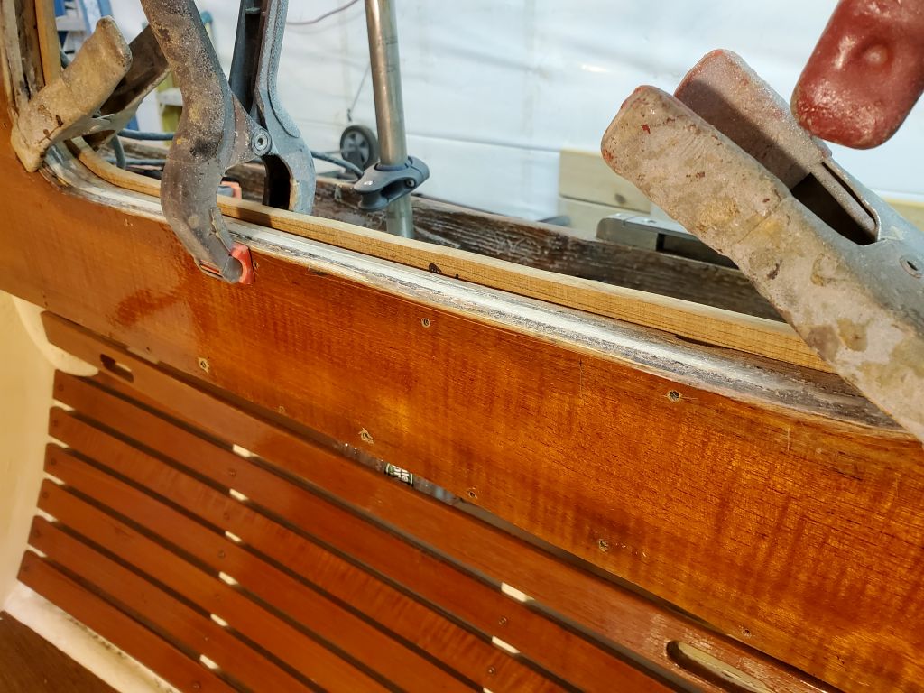
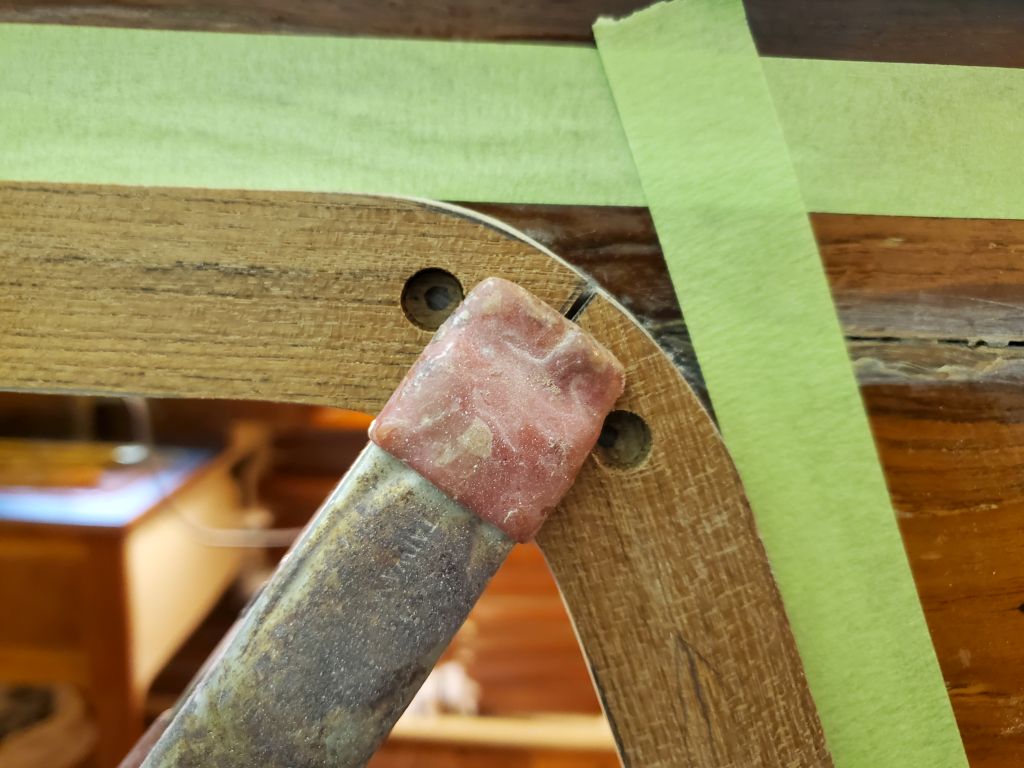
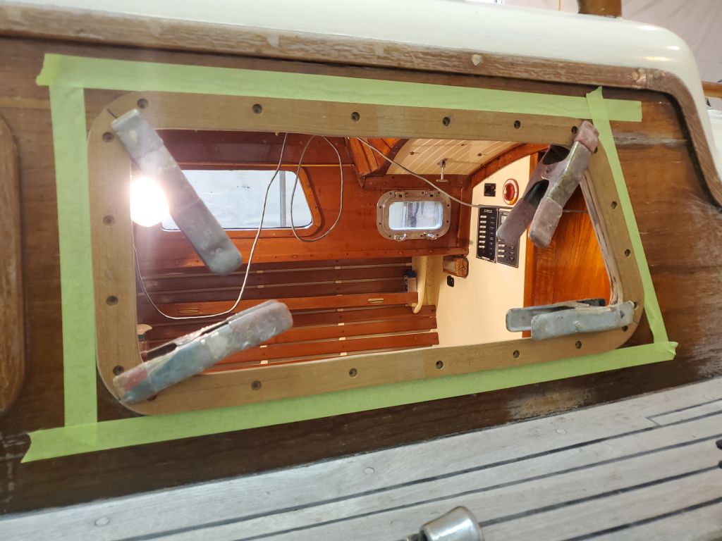
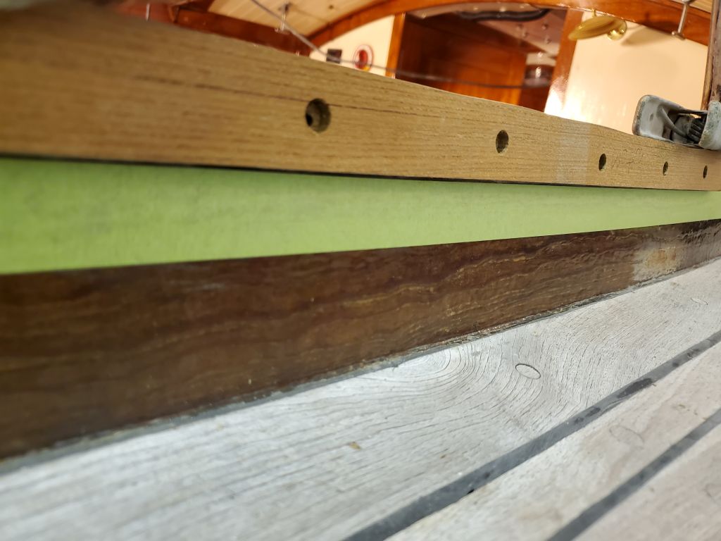
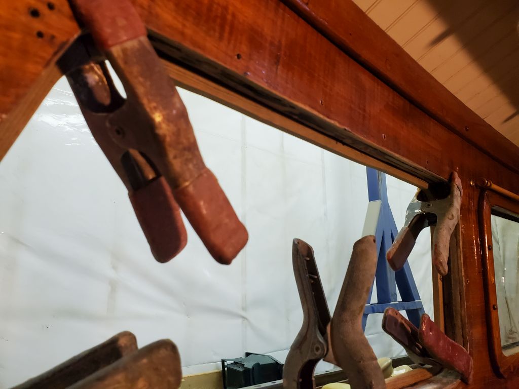
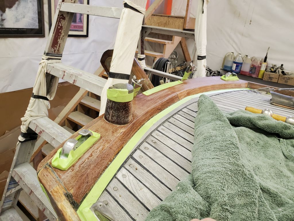
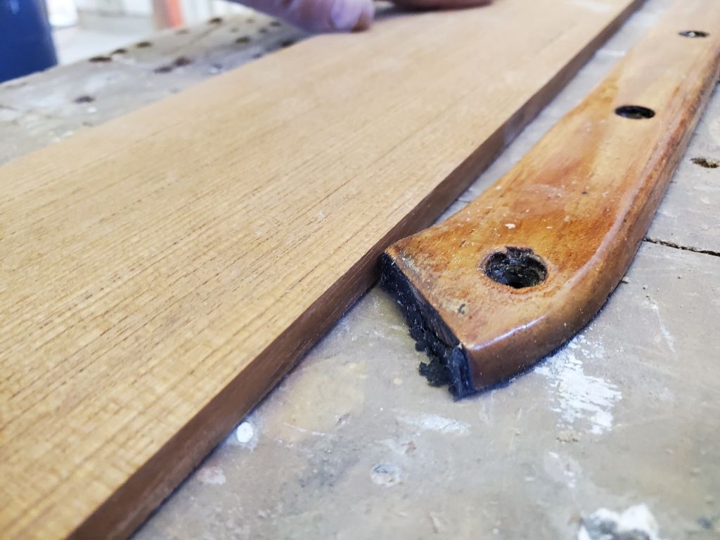
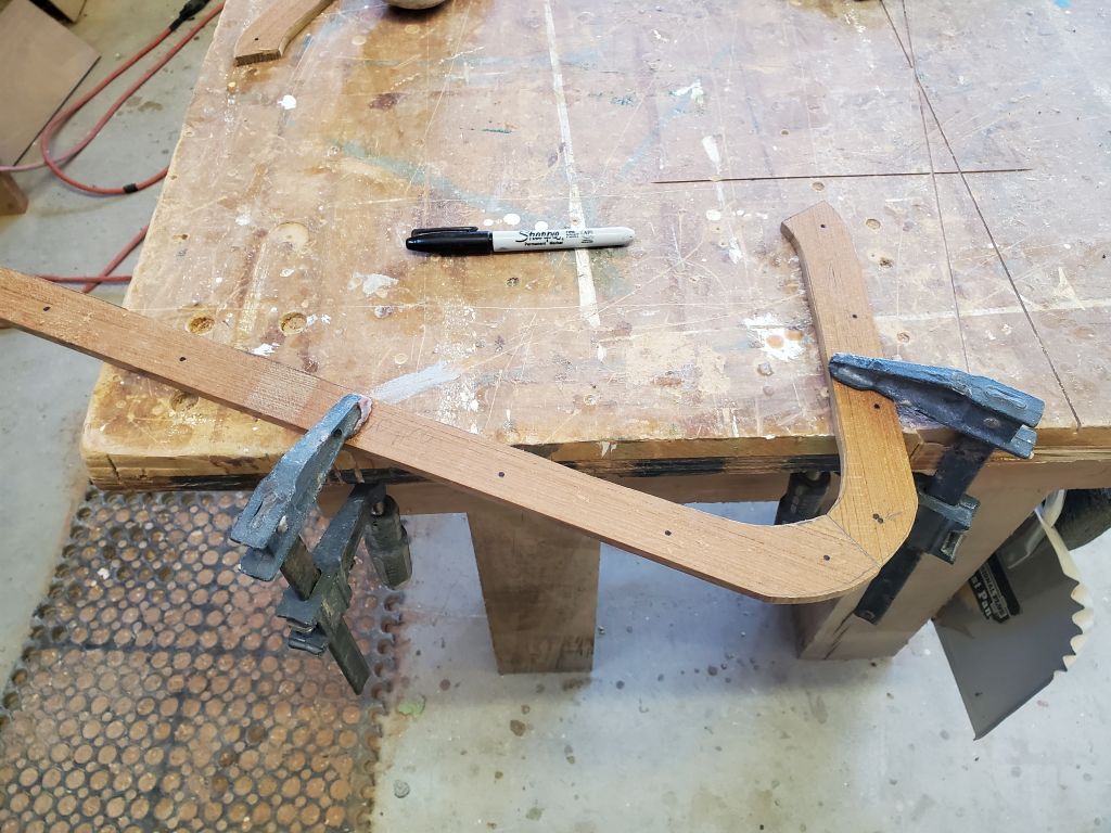
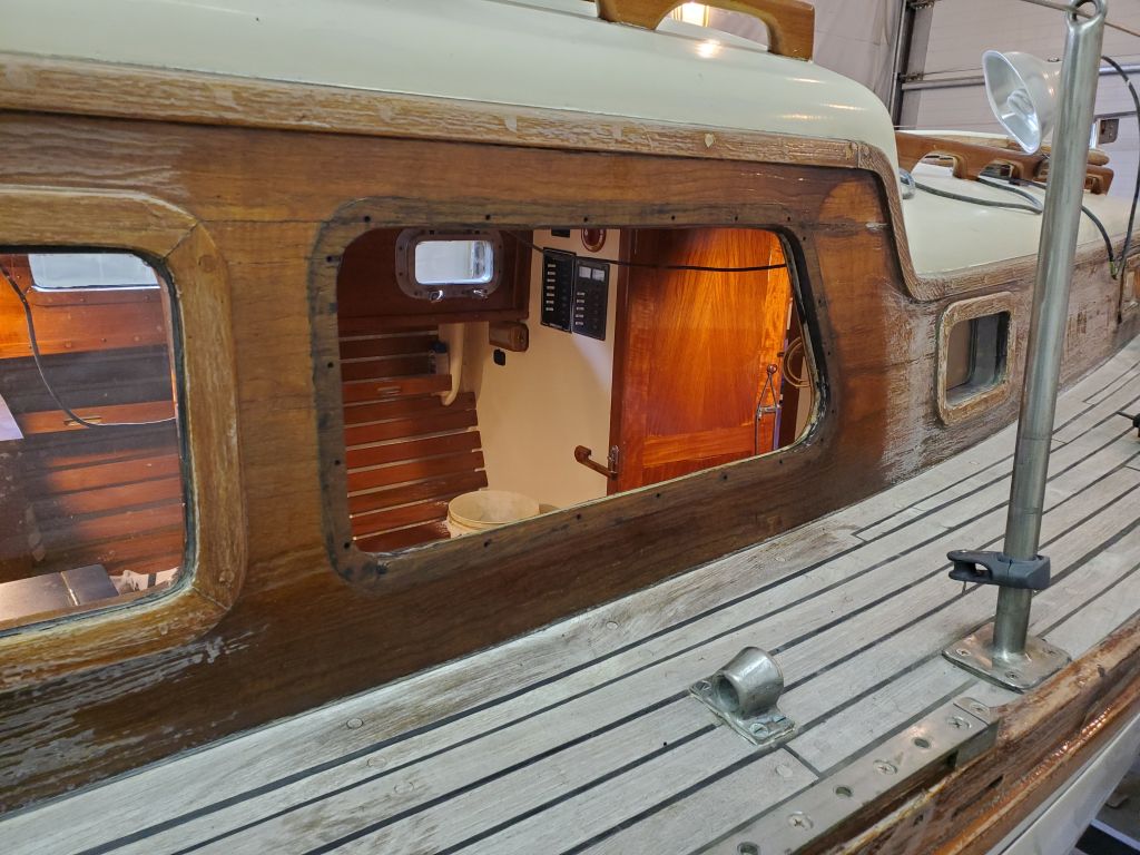
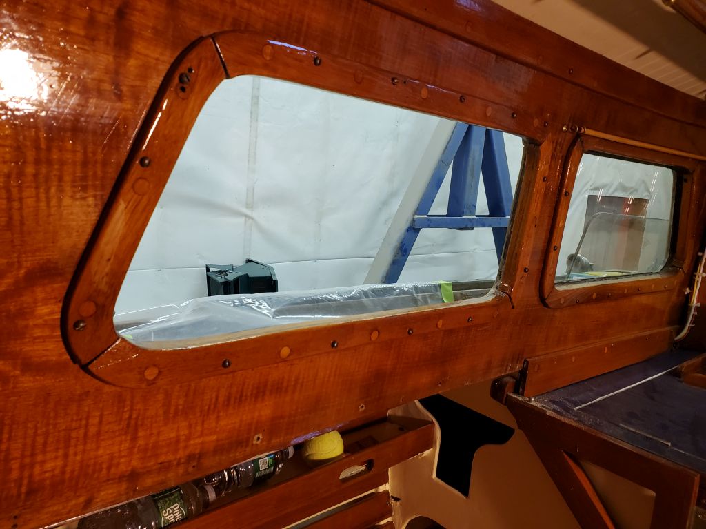
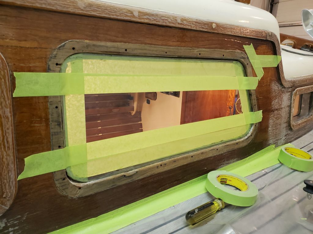
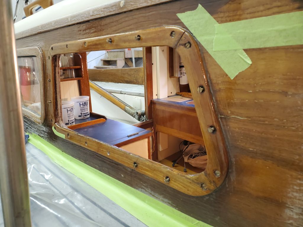
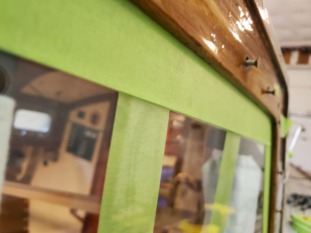
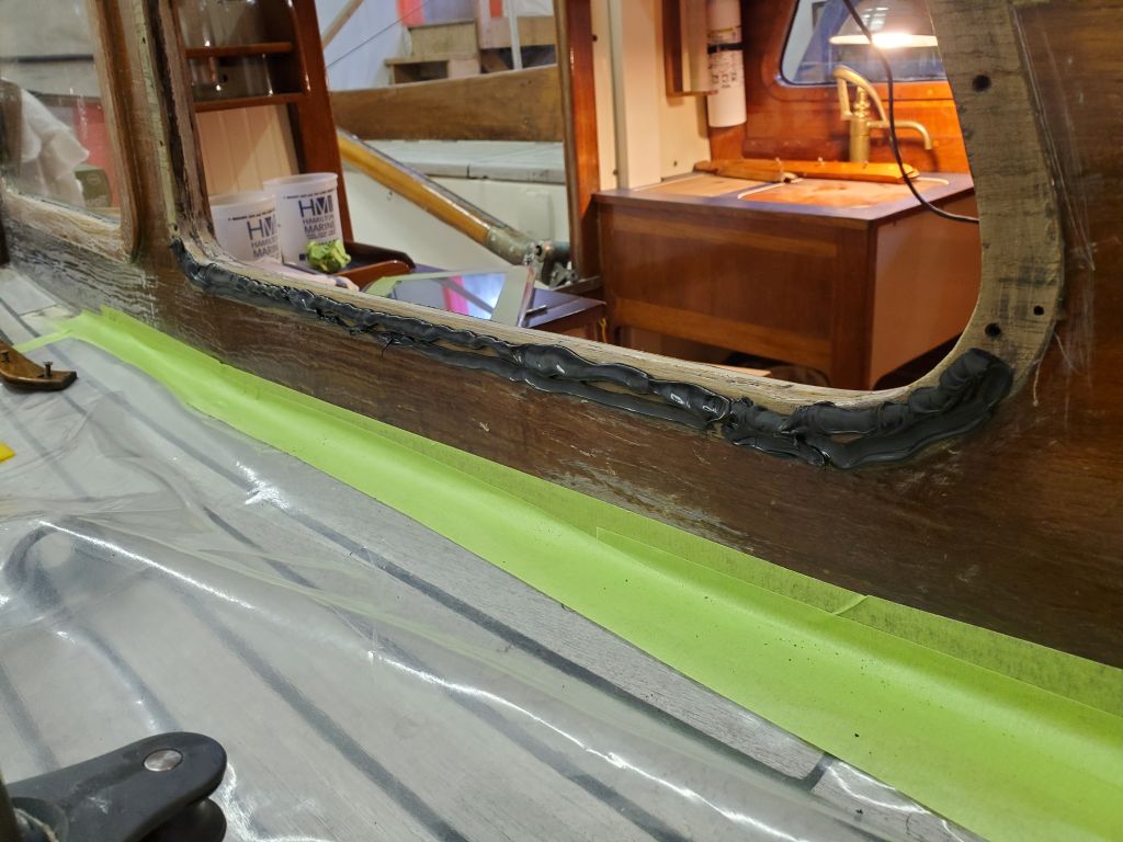
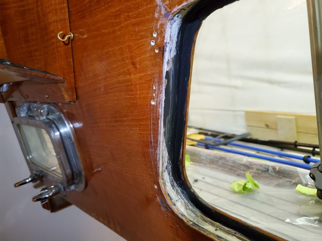
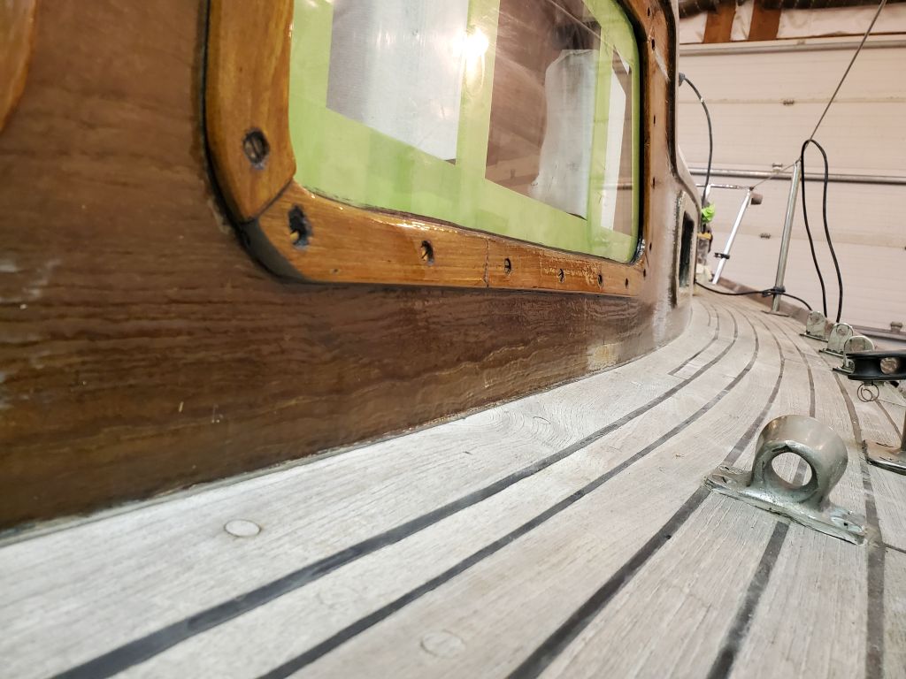
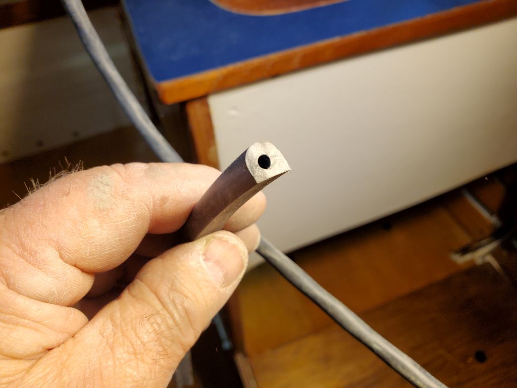
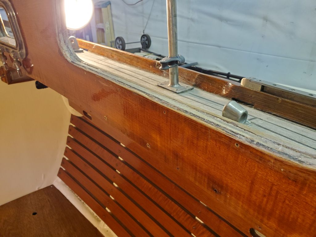
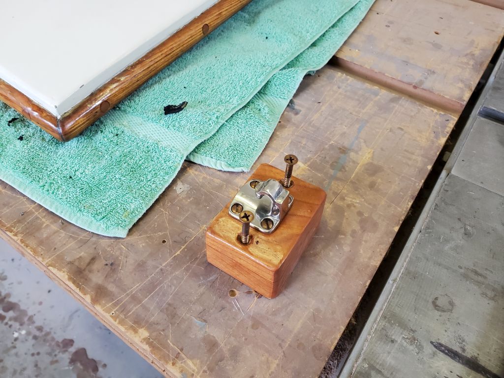
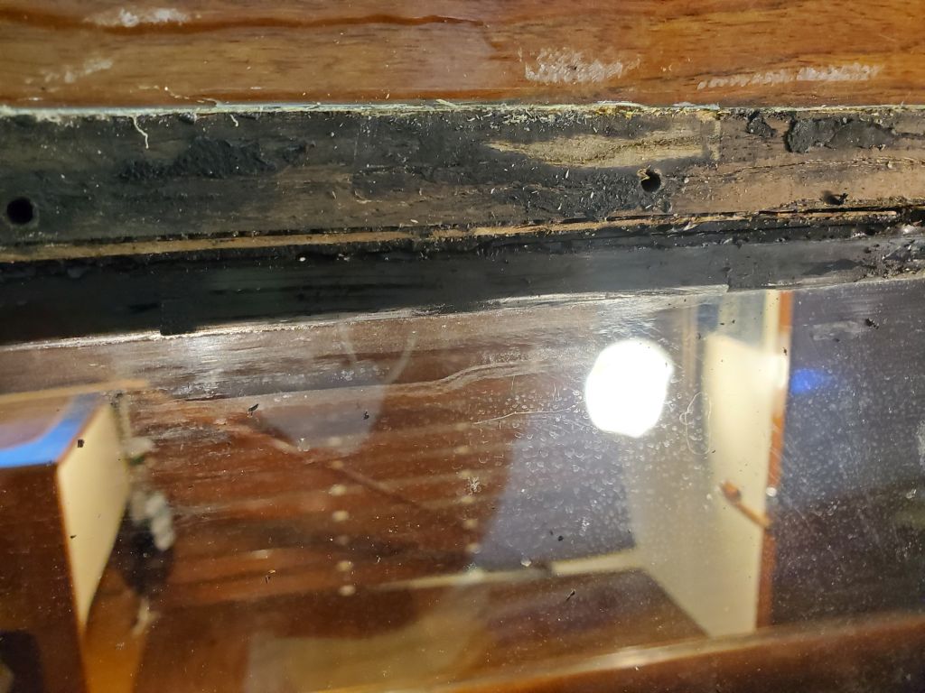
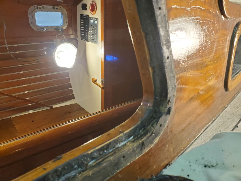
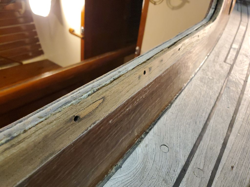
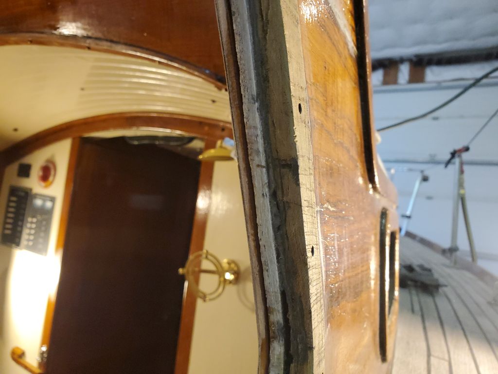
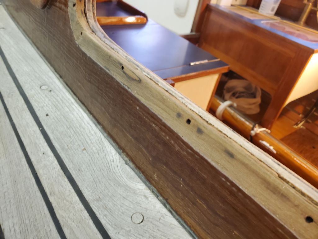
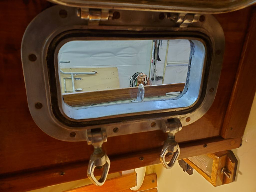
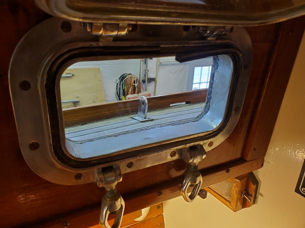
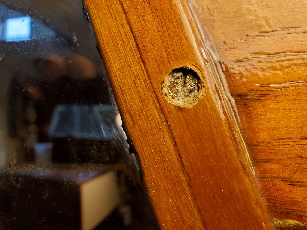
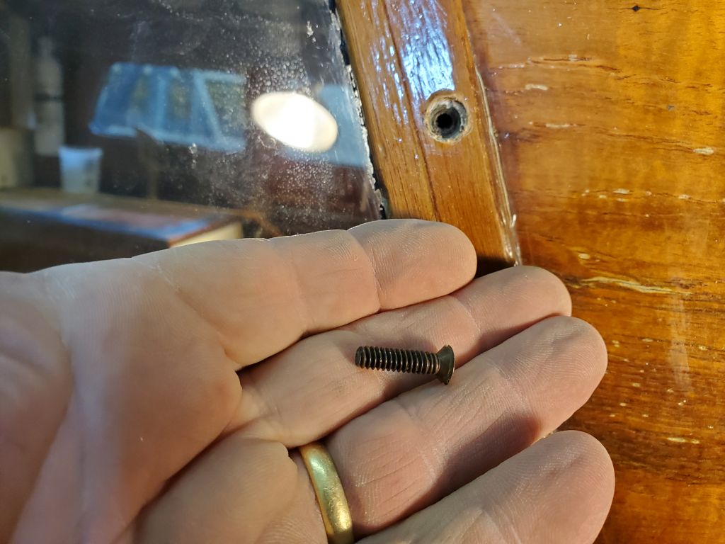
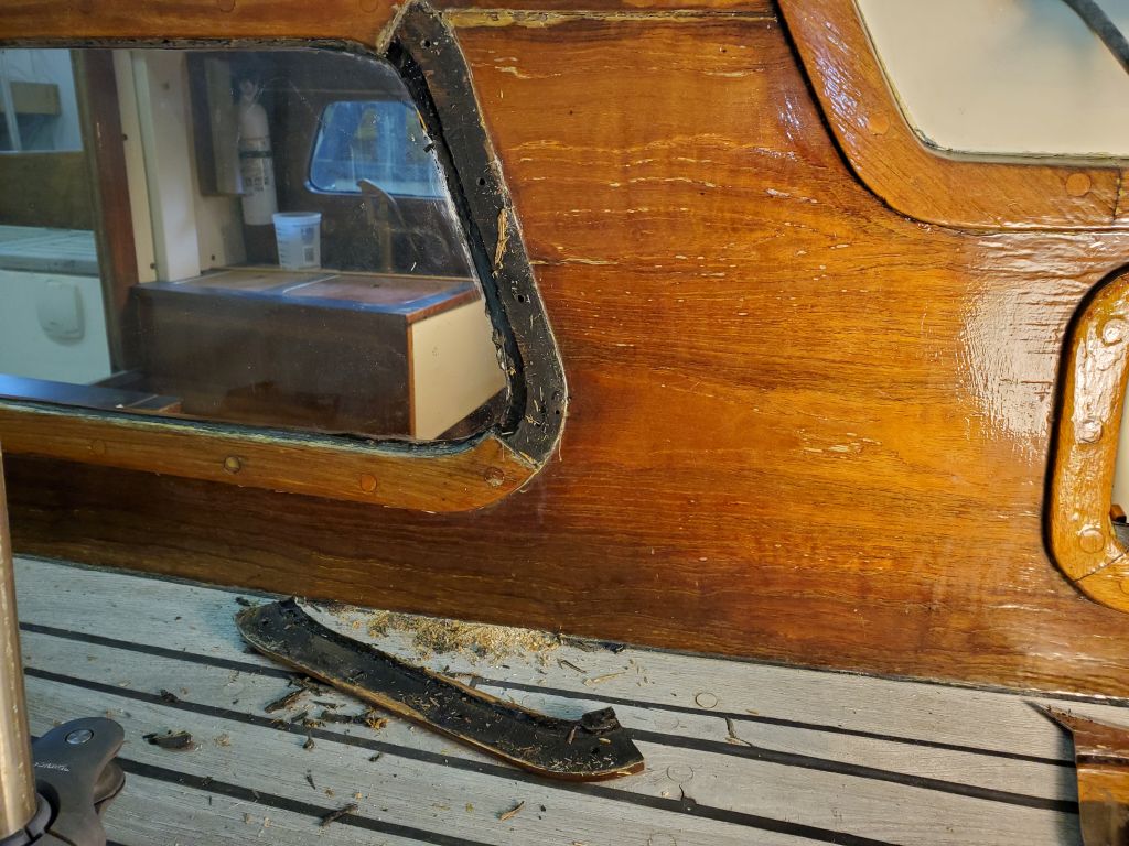
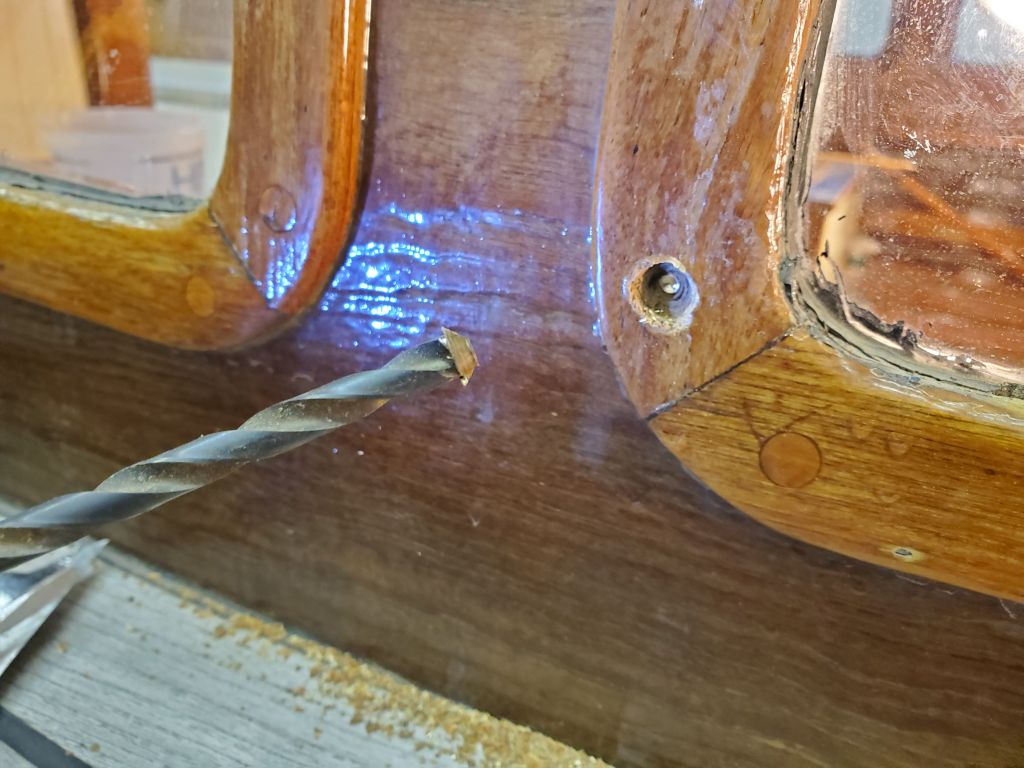
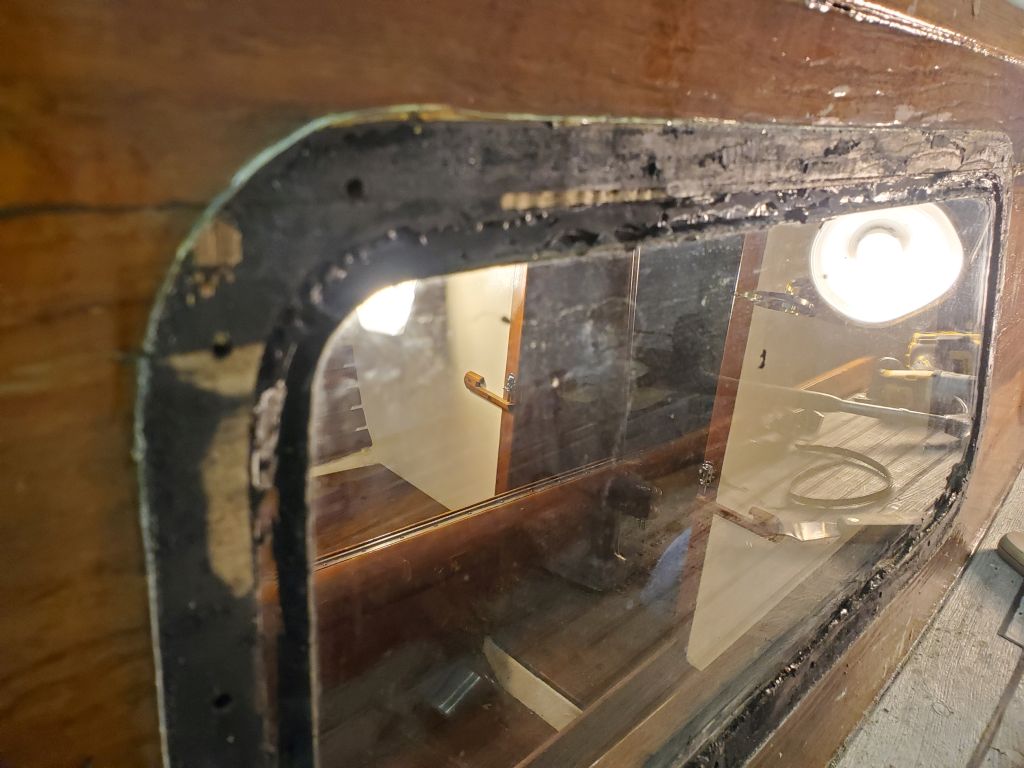
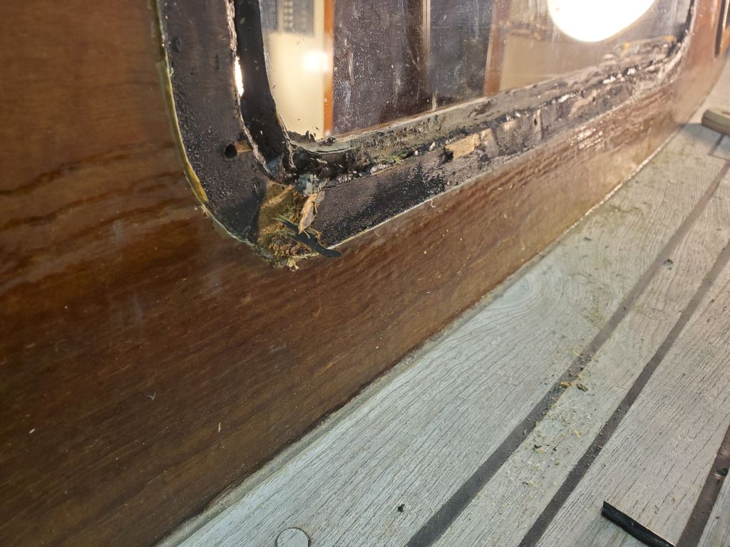
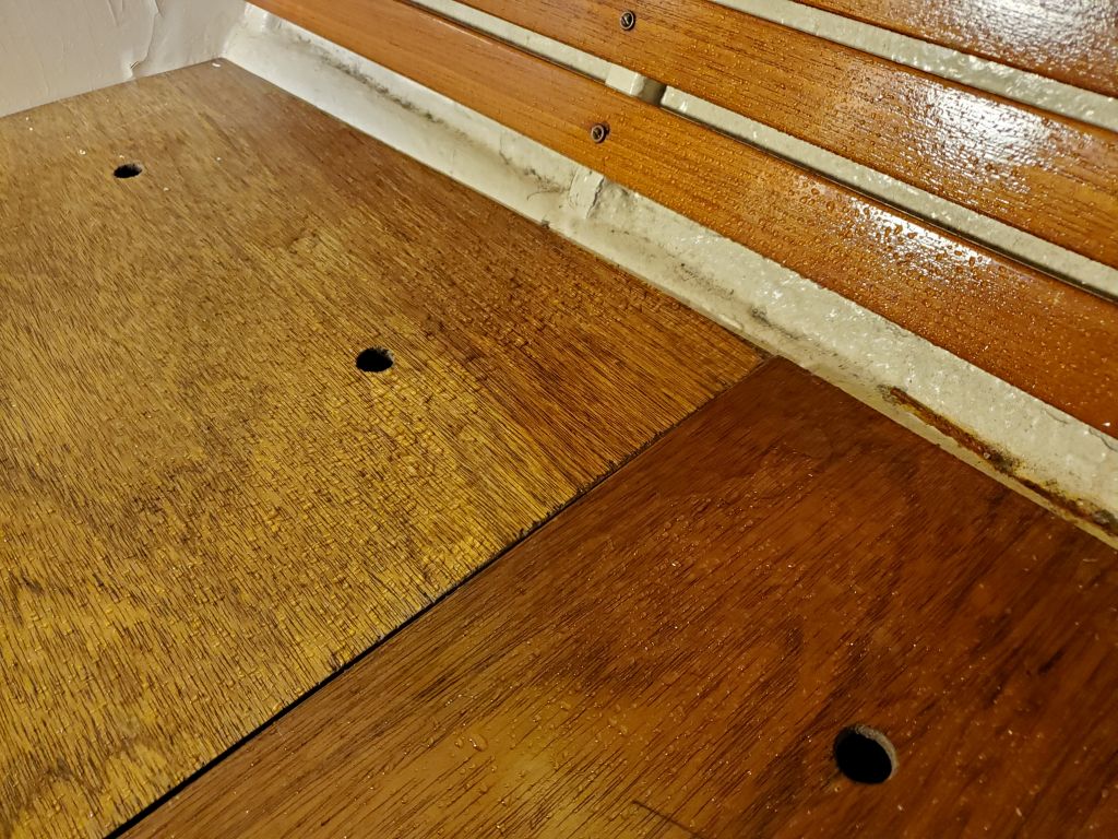
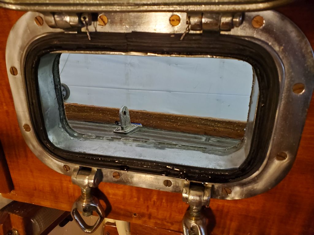
So now I dismantled my setup, and removed the trim from the inside of the opening.  Working from outside, I dry-fit the exterior trim, using at least two screws in each piece driven in all the way to hold it for now, but also partially inserting every other screw to ensure that they all fit correctly and would thread in as needed.  I had to clean out a couple of the screw holes with a tap.

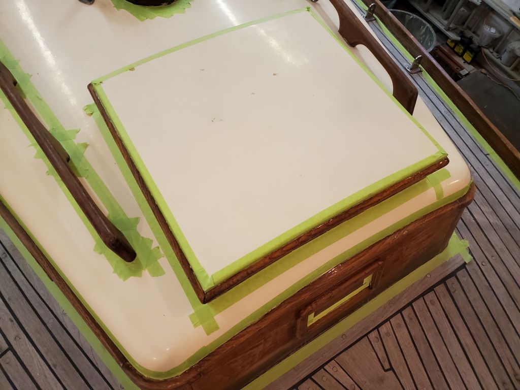
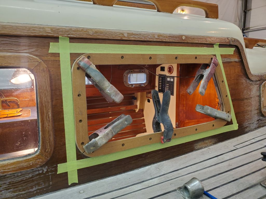
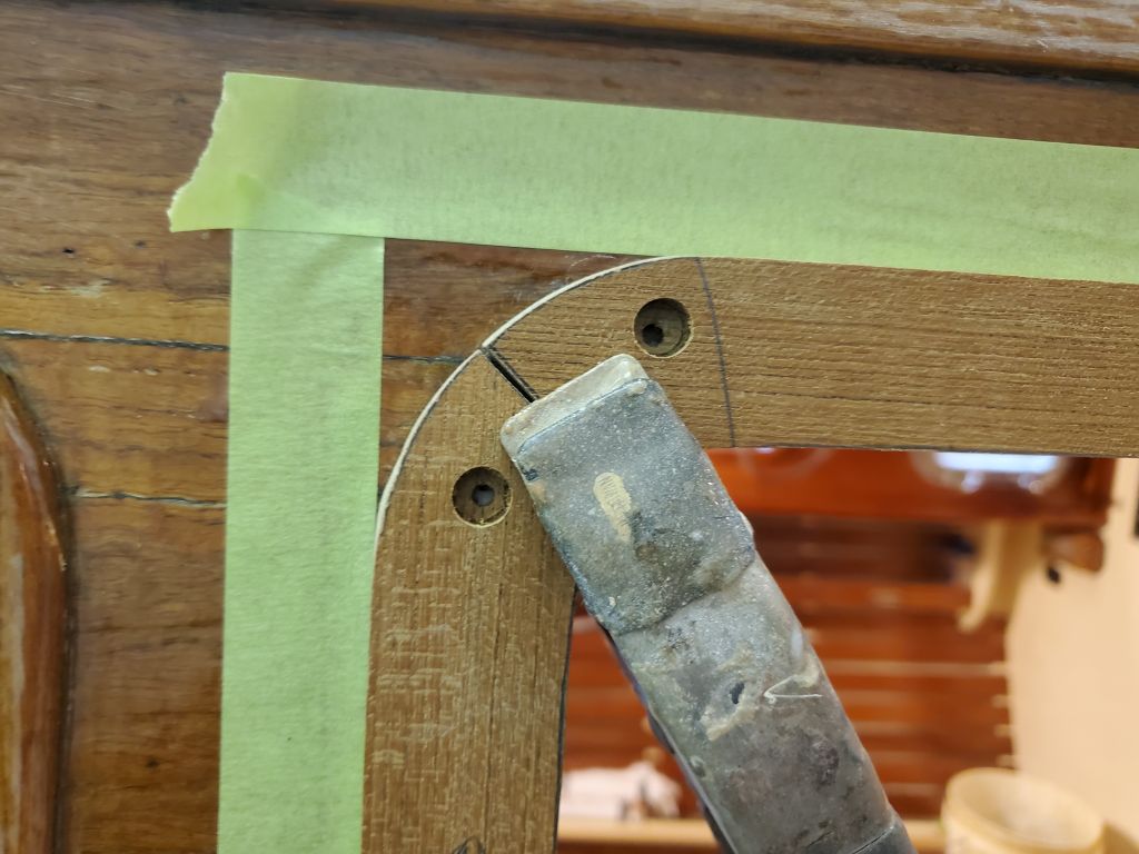
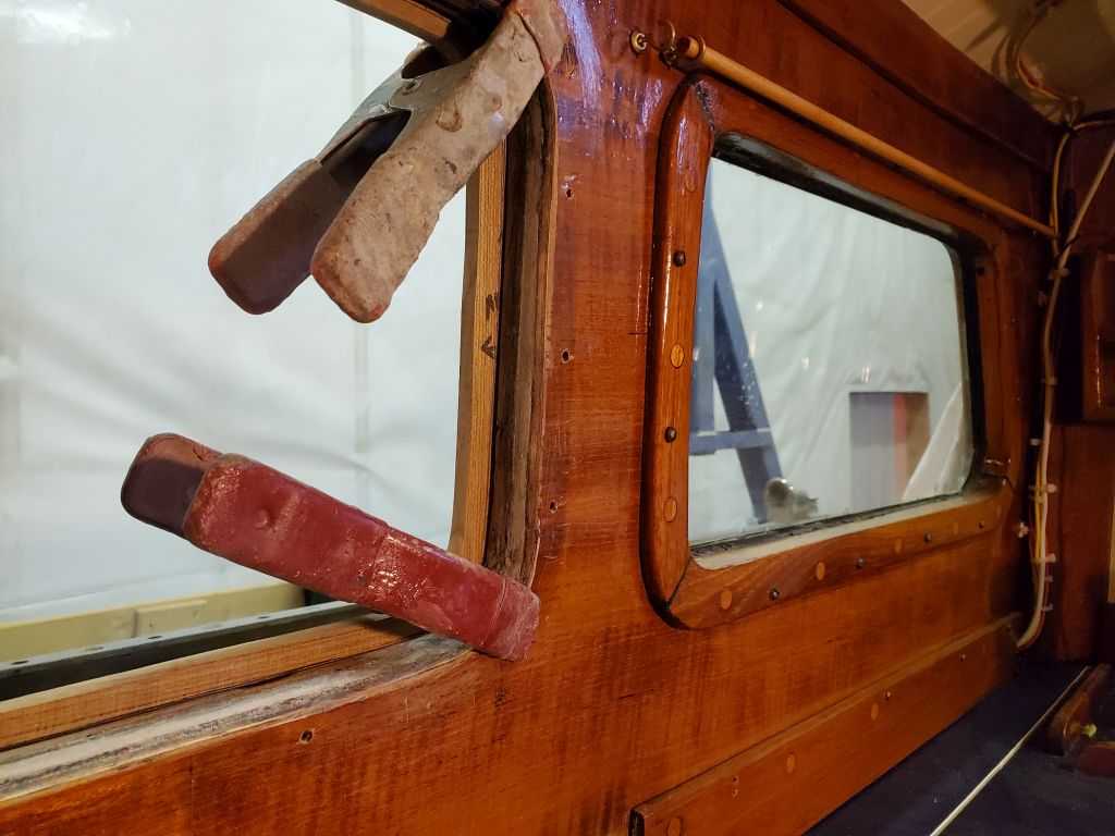
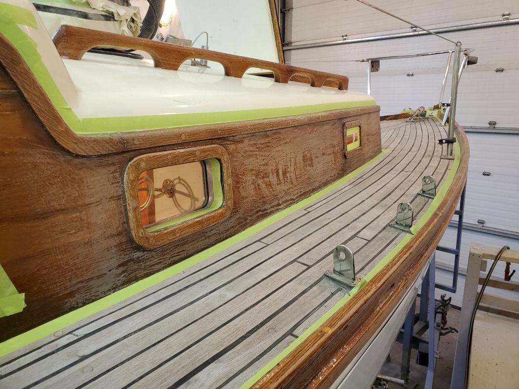
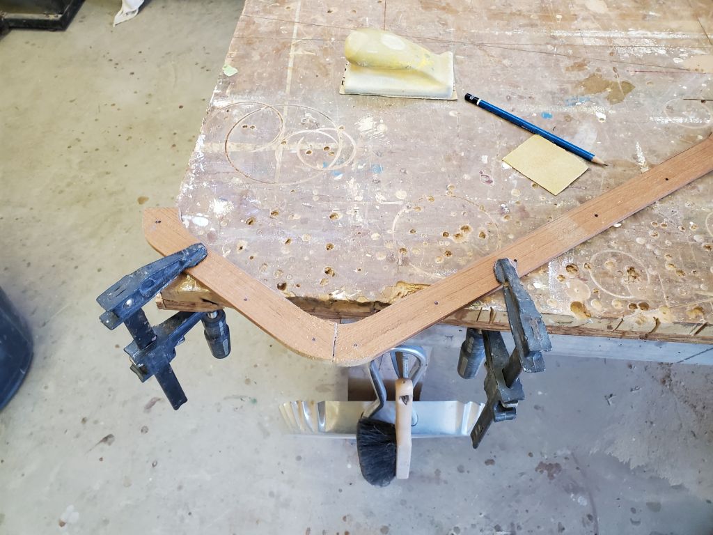
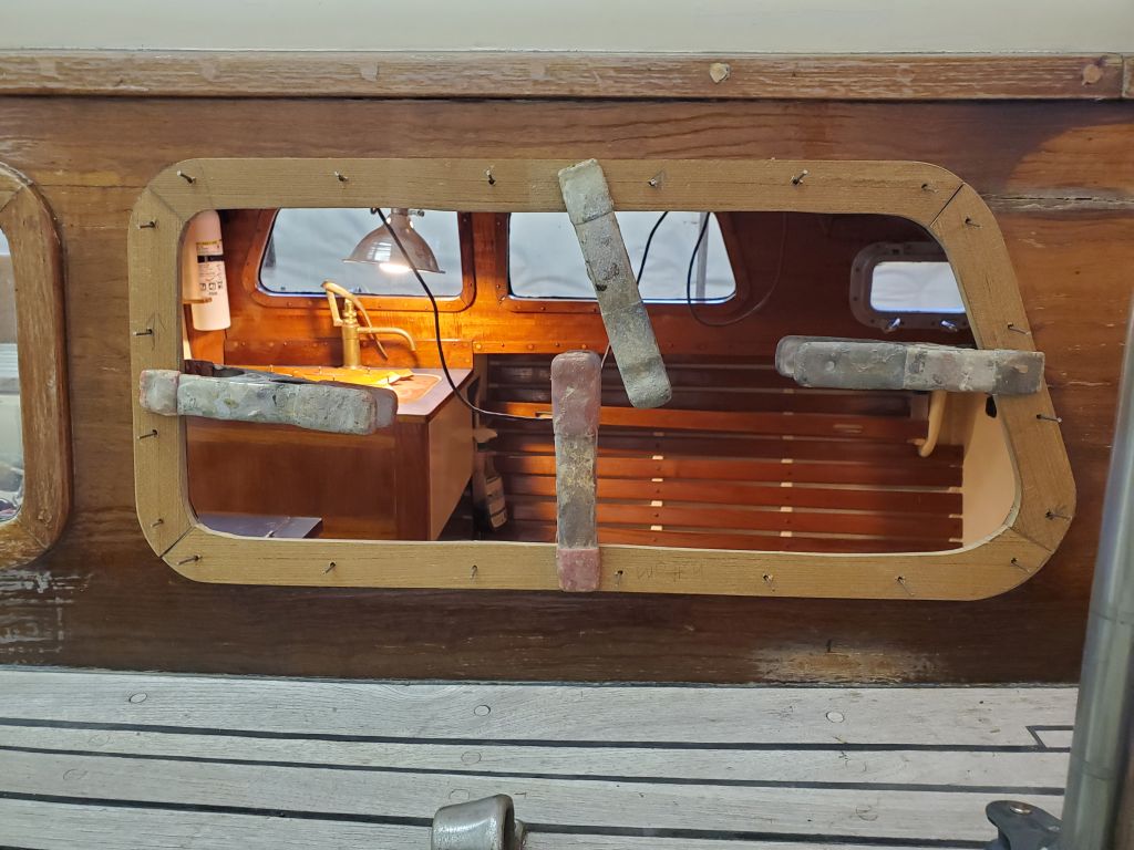
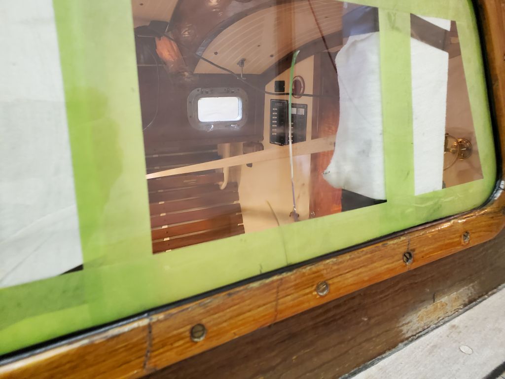
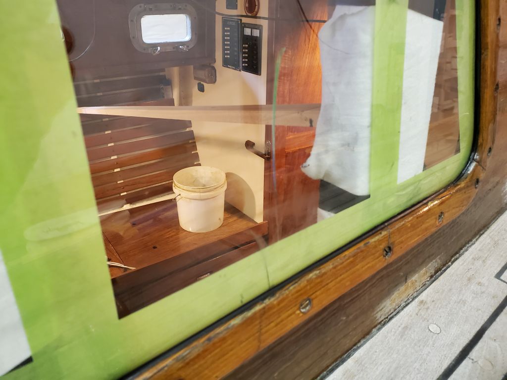
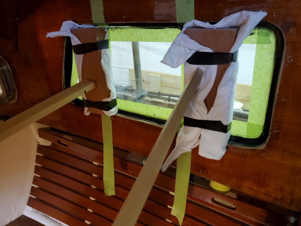
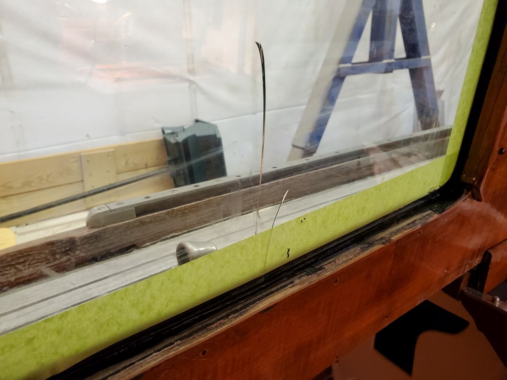
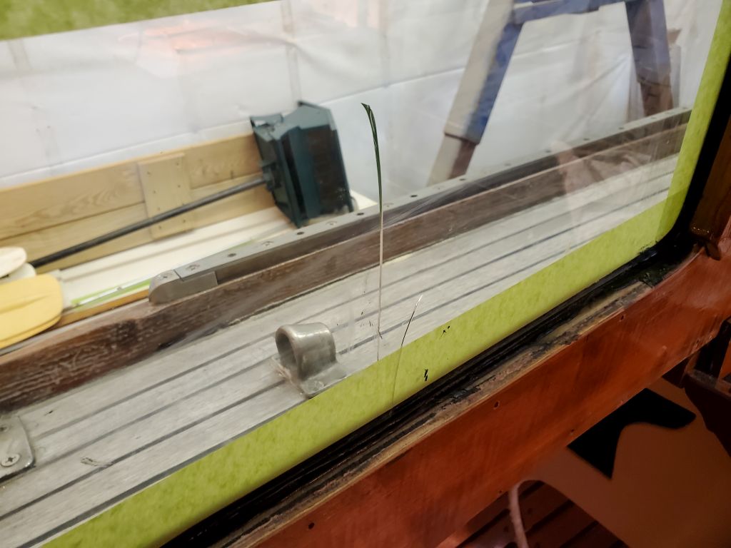
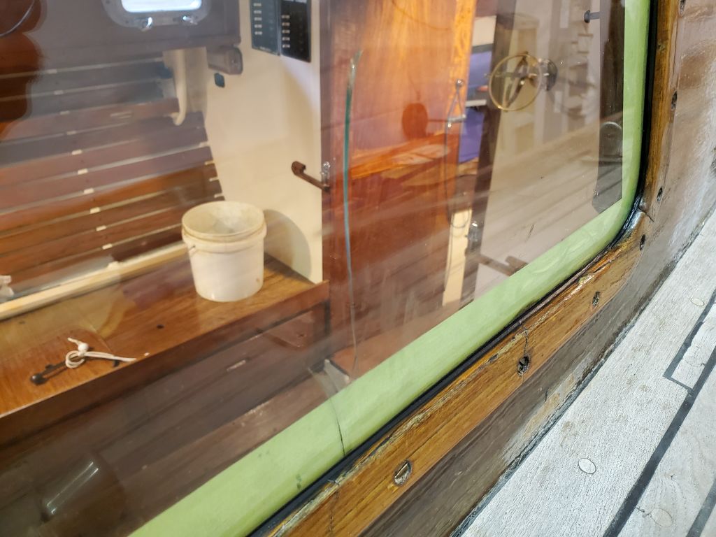
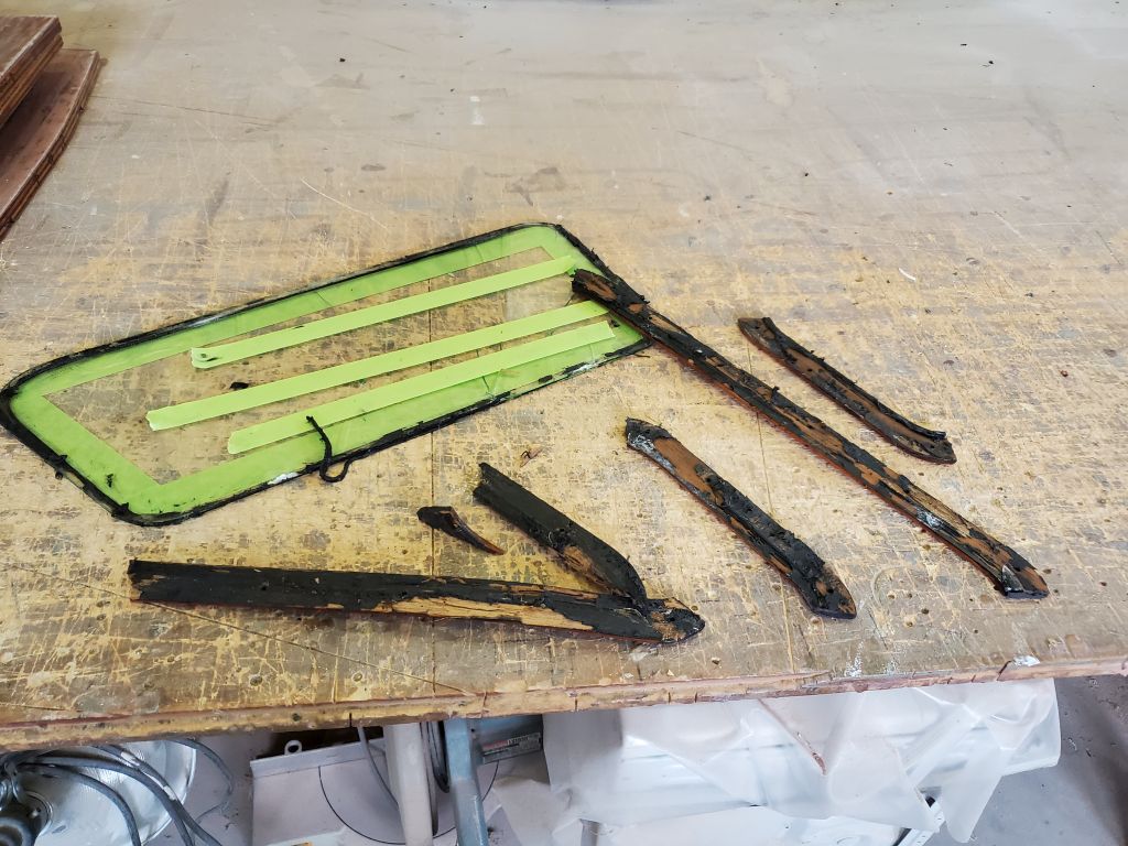
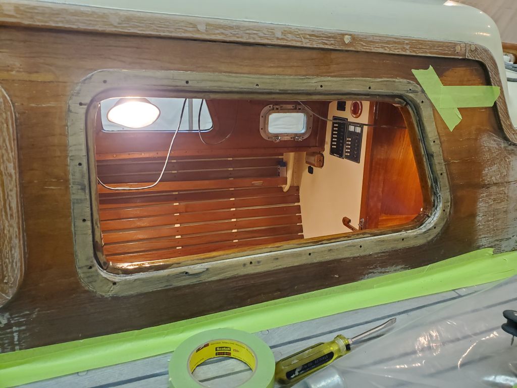
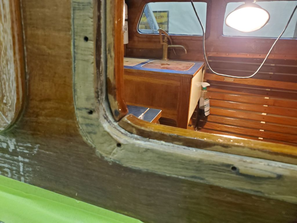
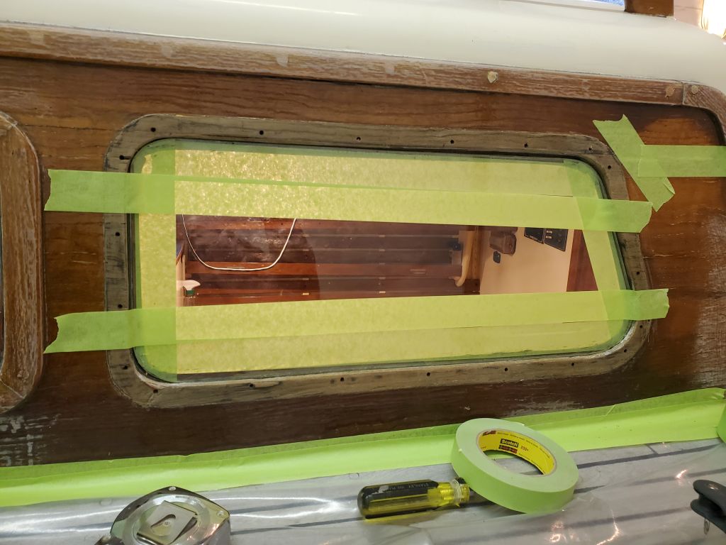
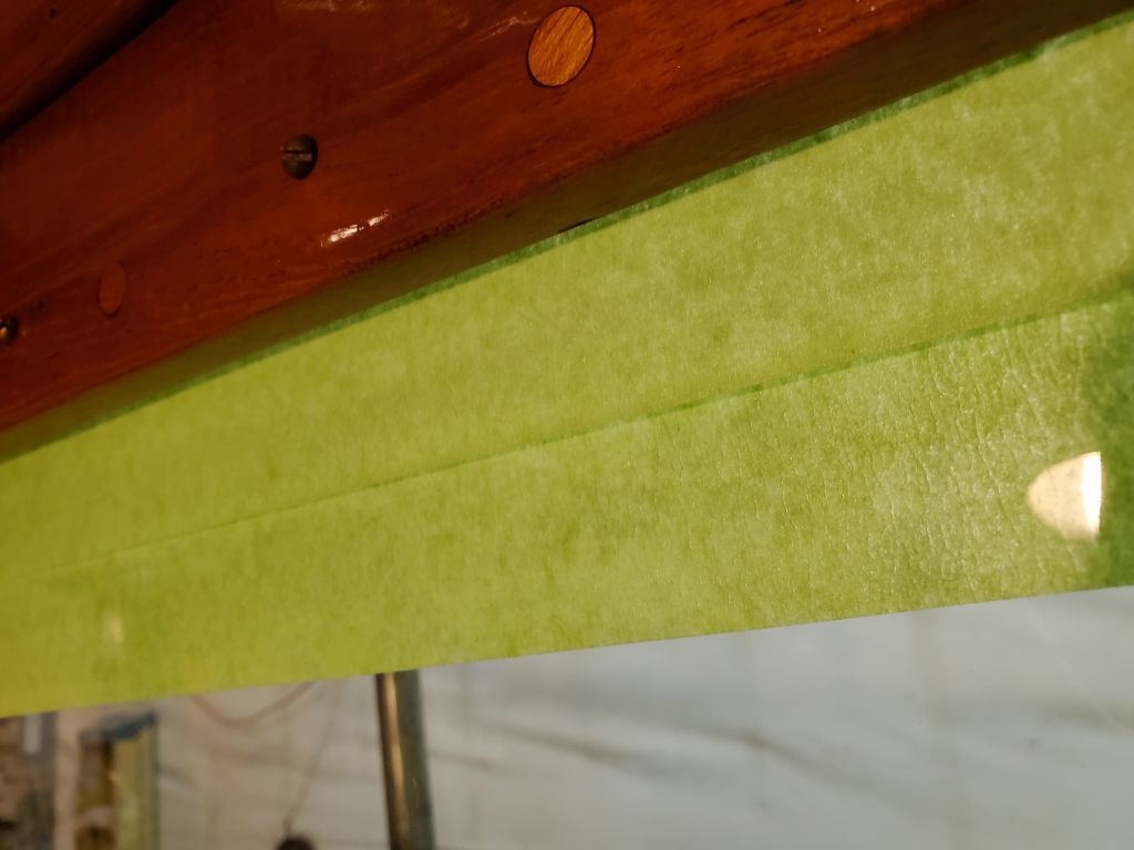
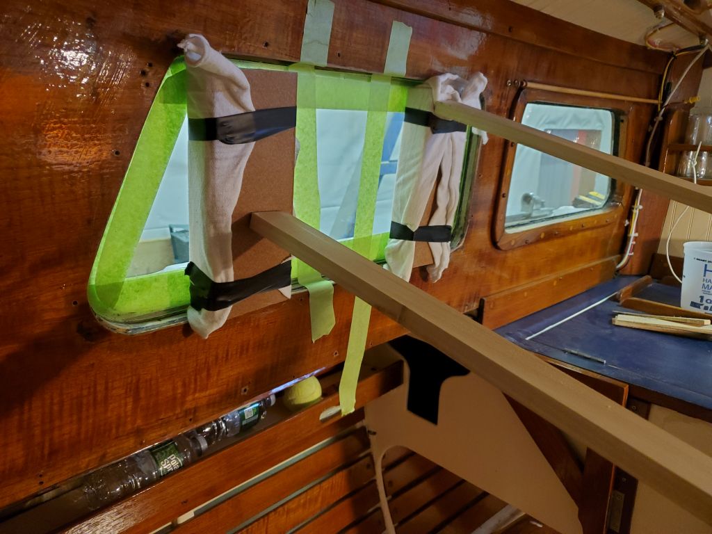
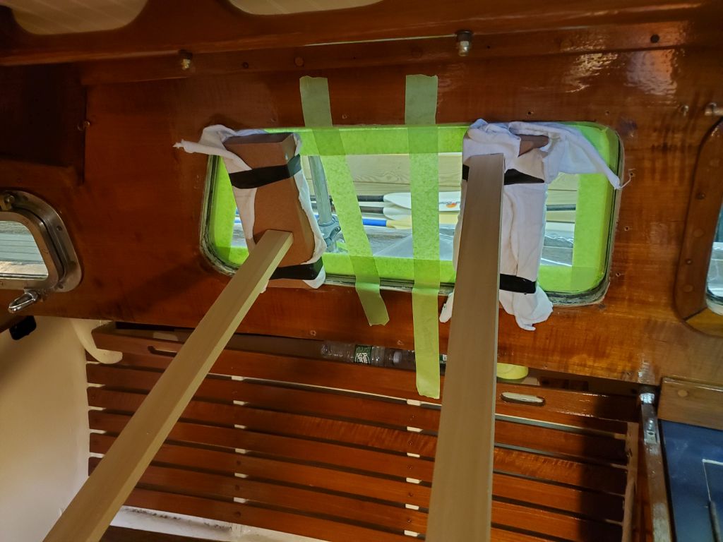
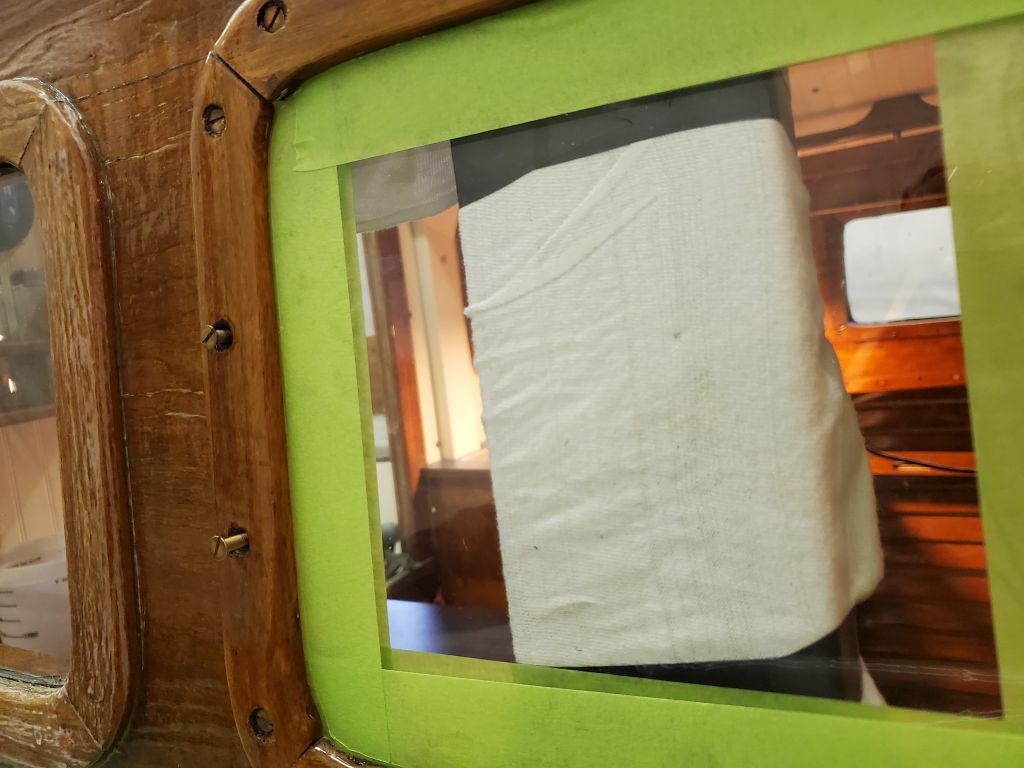
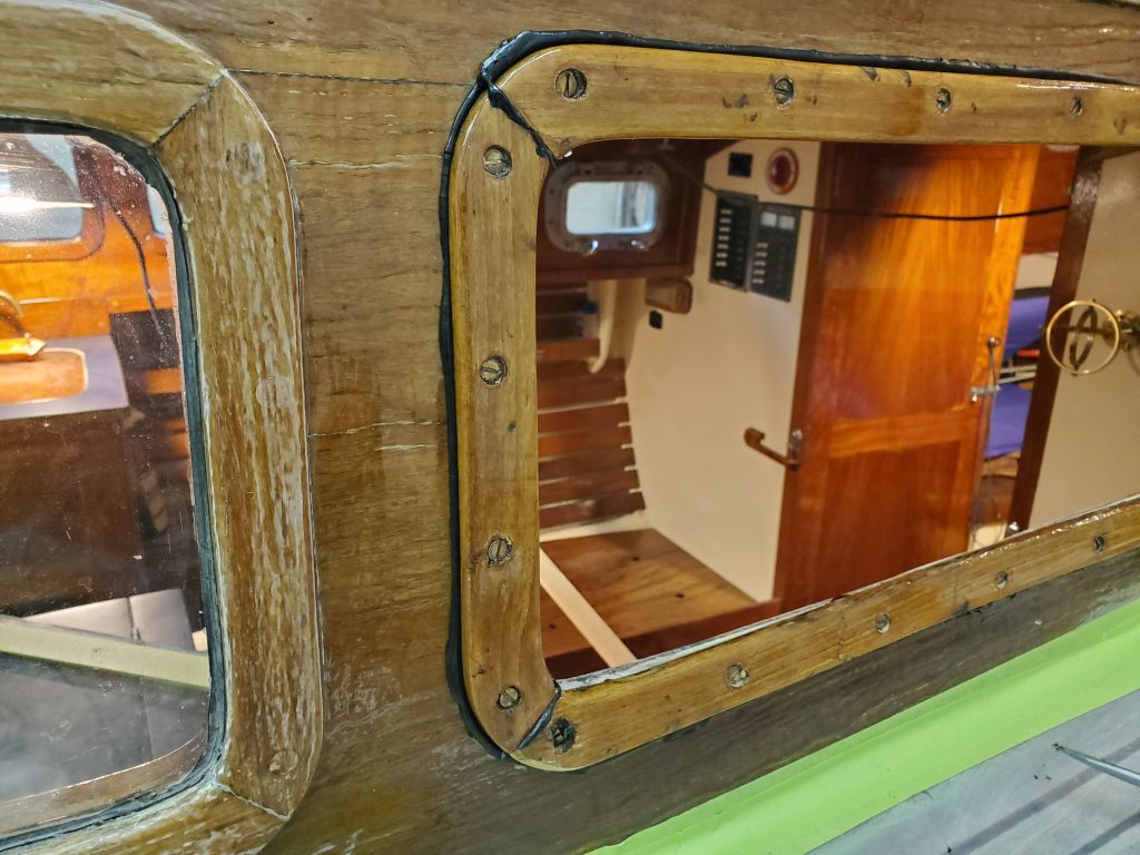
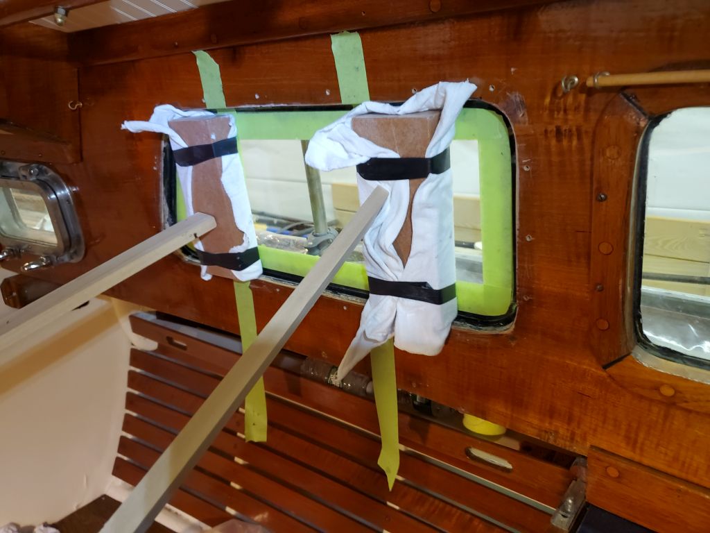
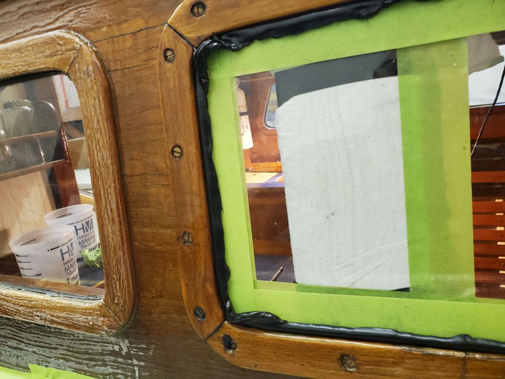
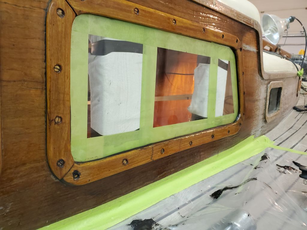
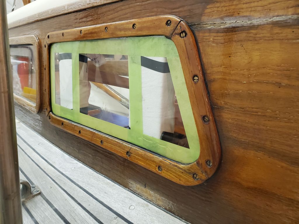
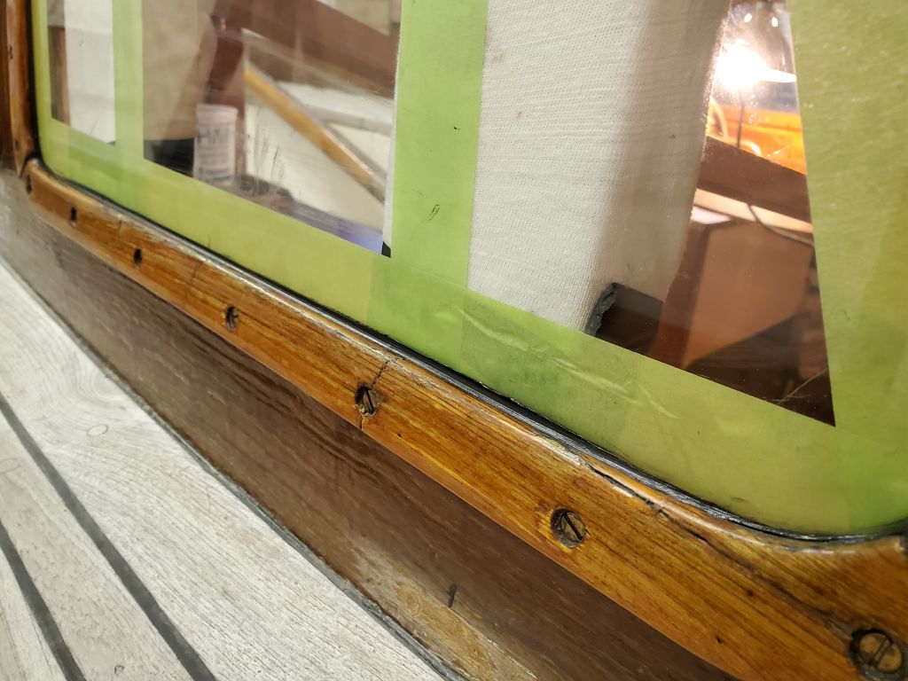
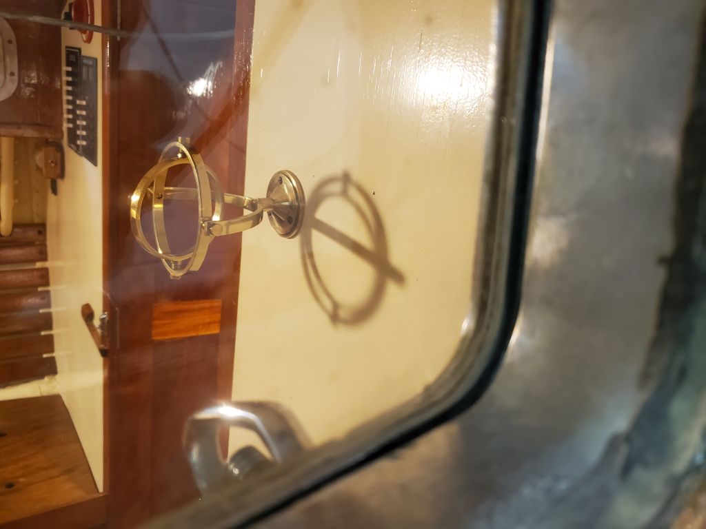
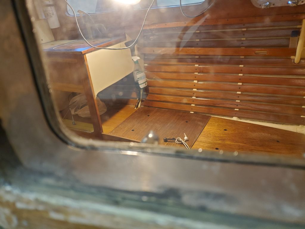
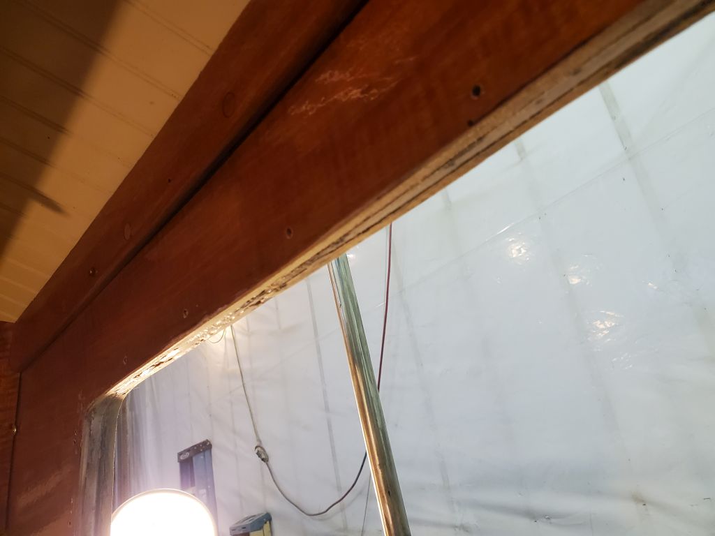
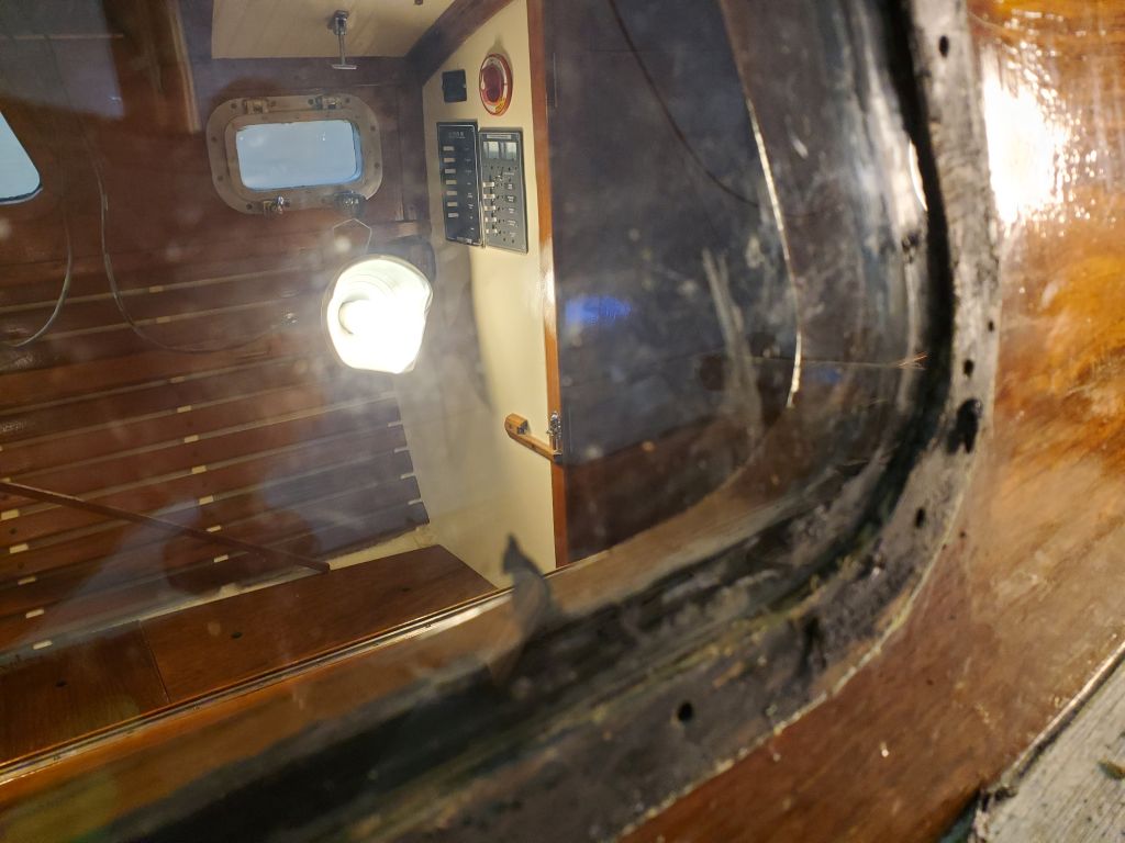
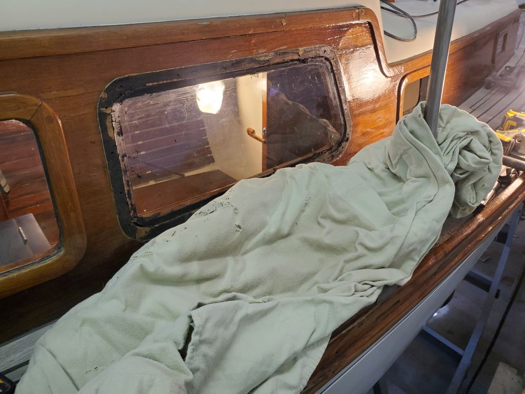
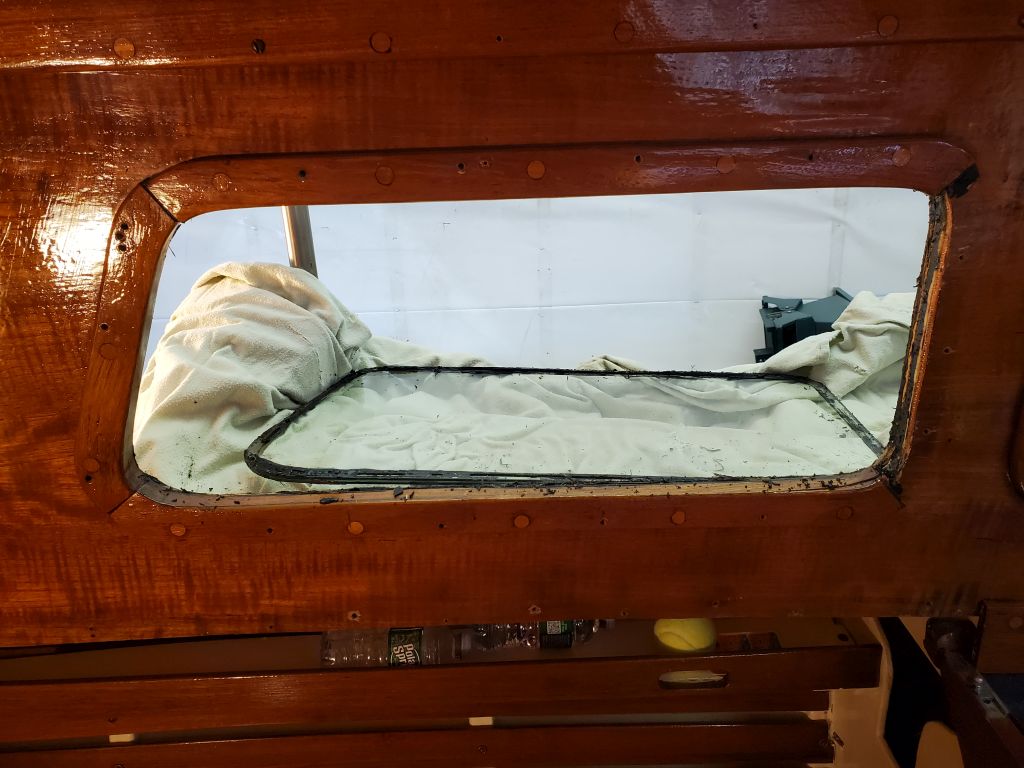
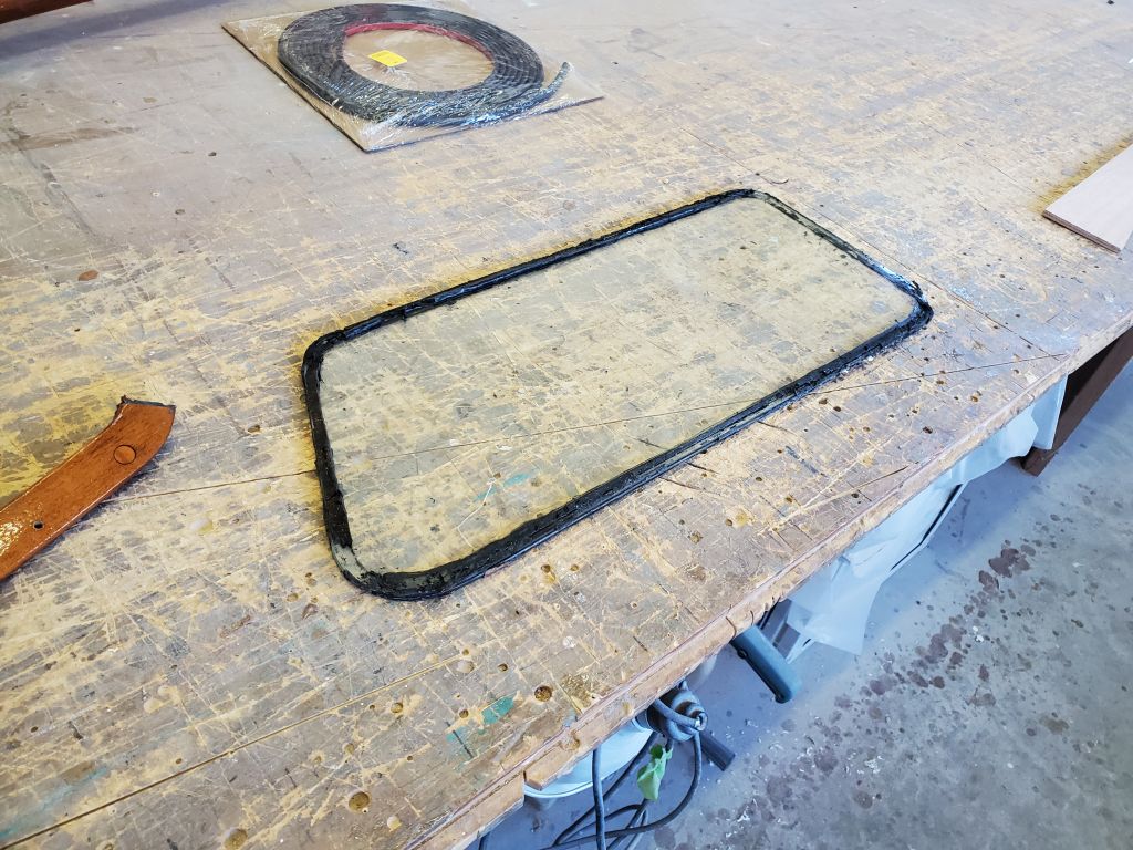
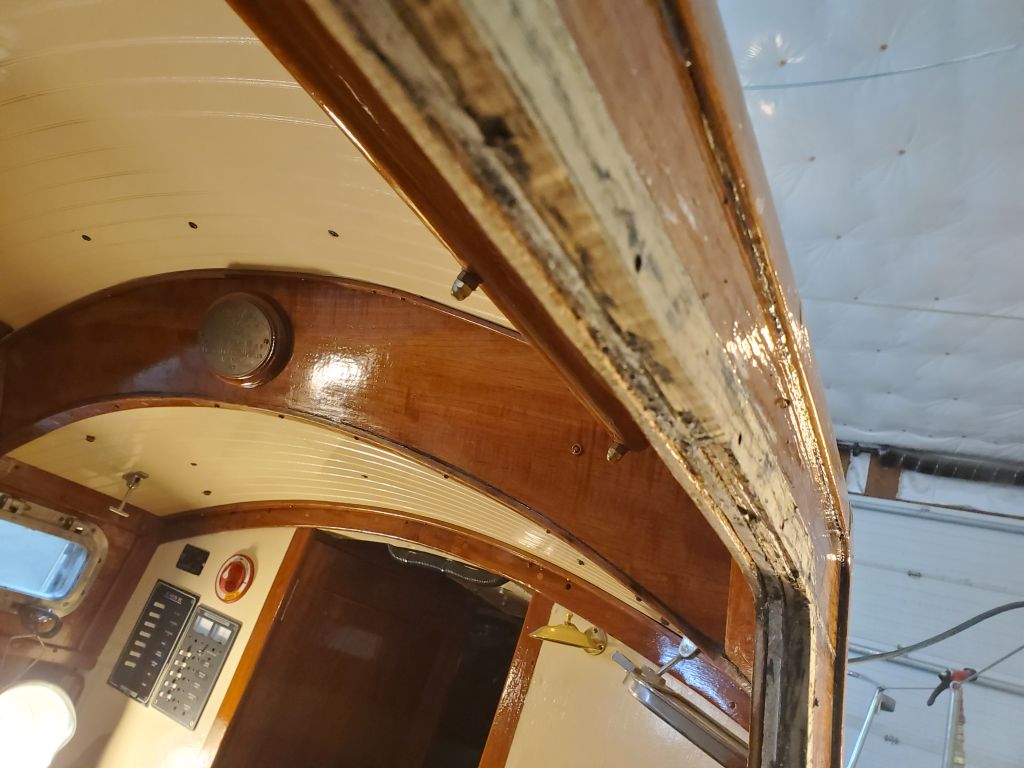
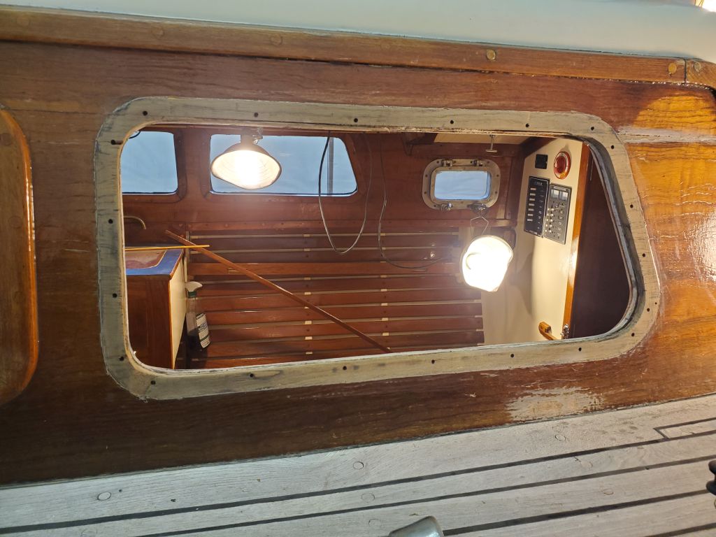
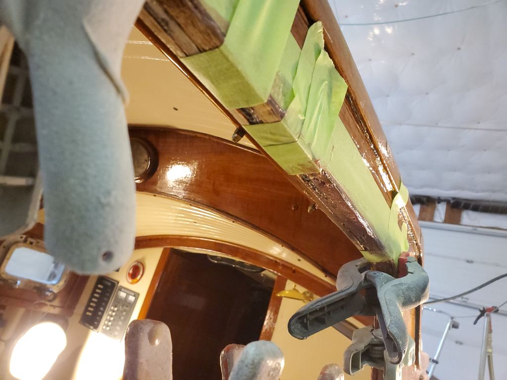
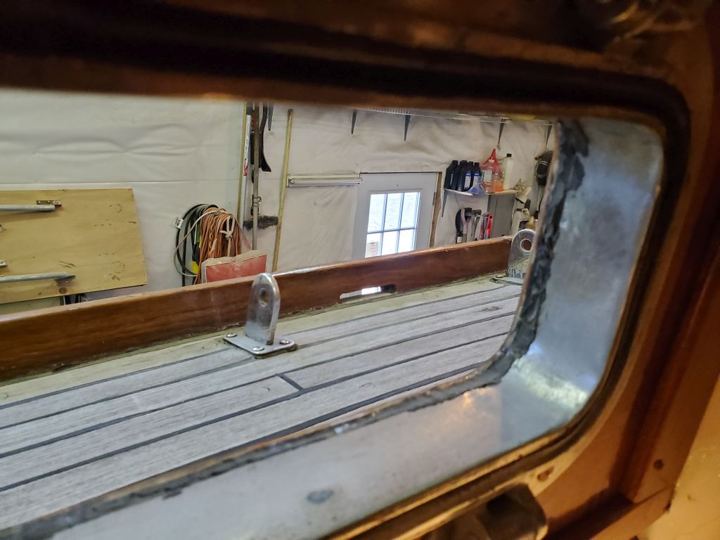
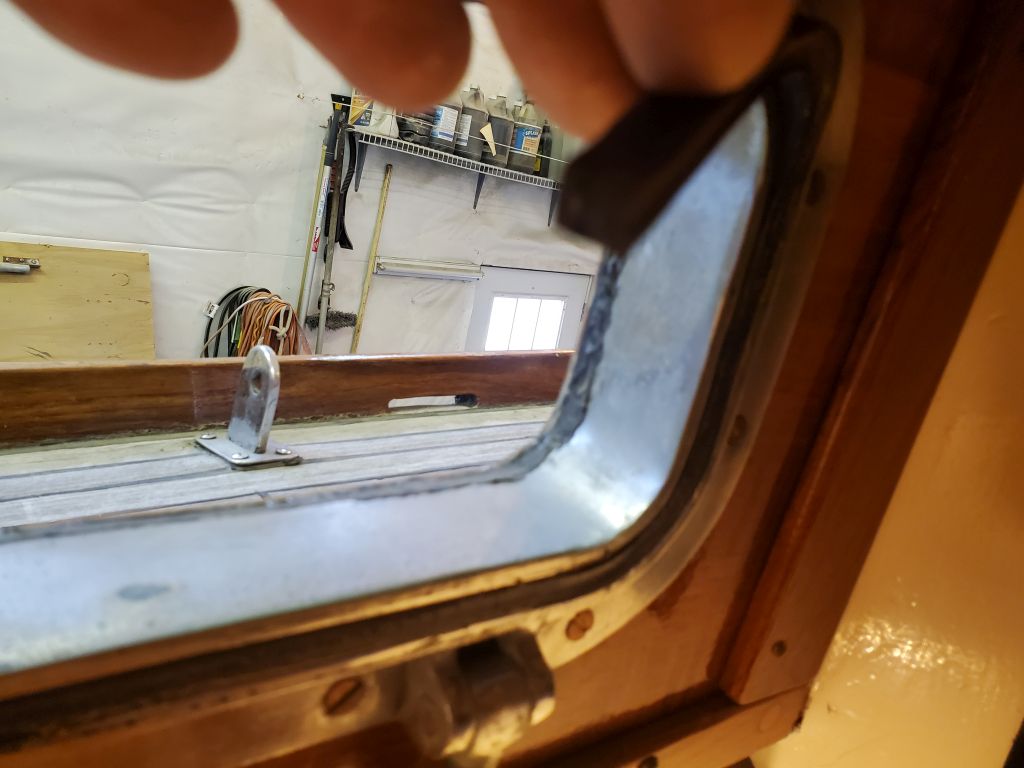
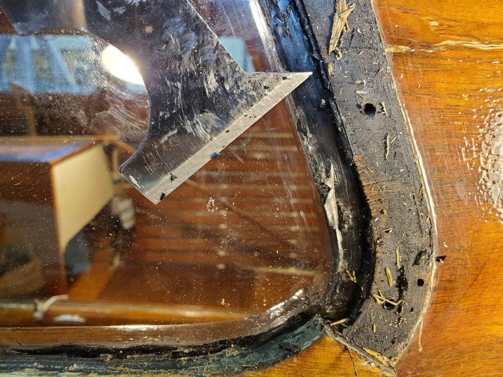
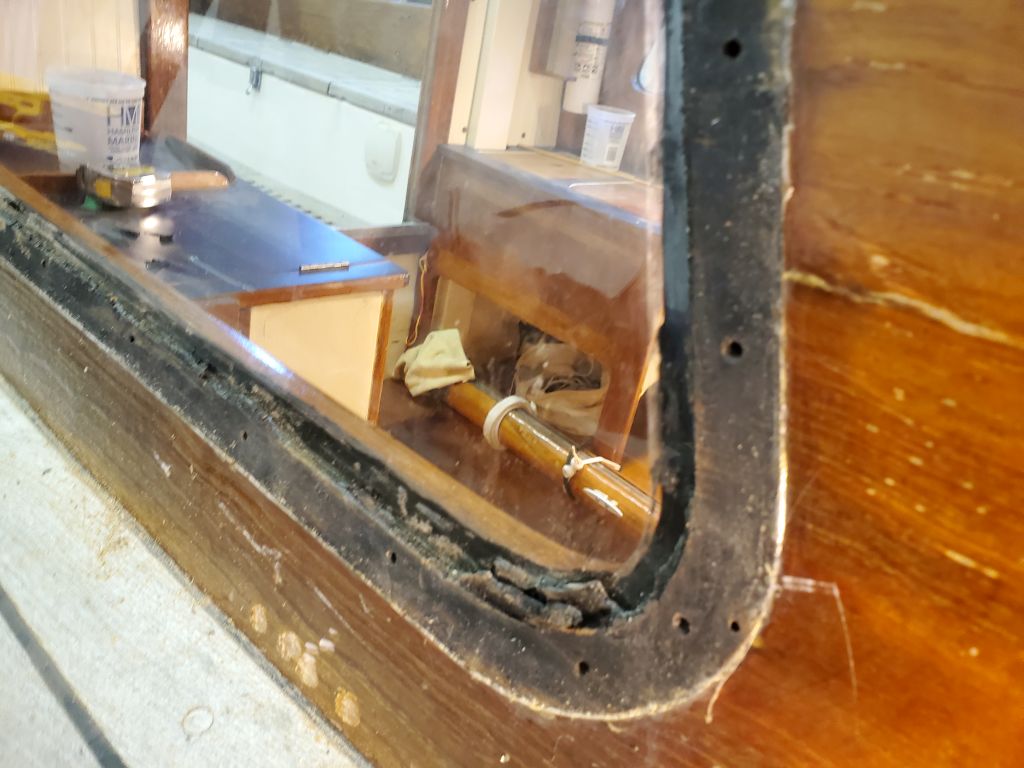
I masked over the edges of the outside face of the lens, then, from inside, placed it in the opening, holding it with some tape and then some braces extending across the cabin to apply light pressure.  Then, from outside, I ran a knife around the edge of the trim to score the tape so I could remove the section beneath the trim later.

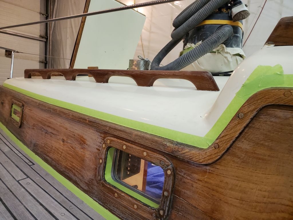
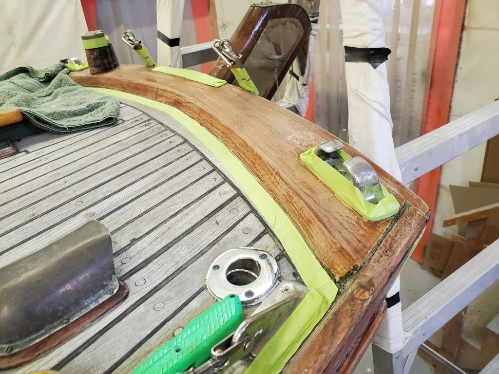
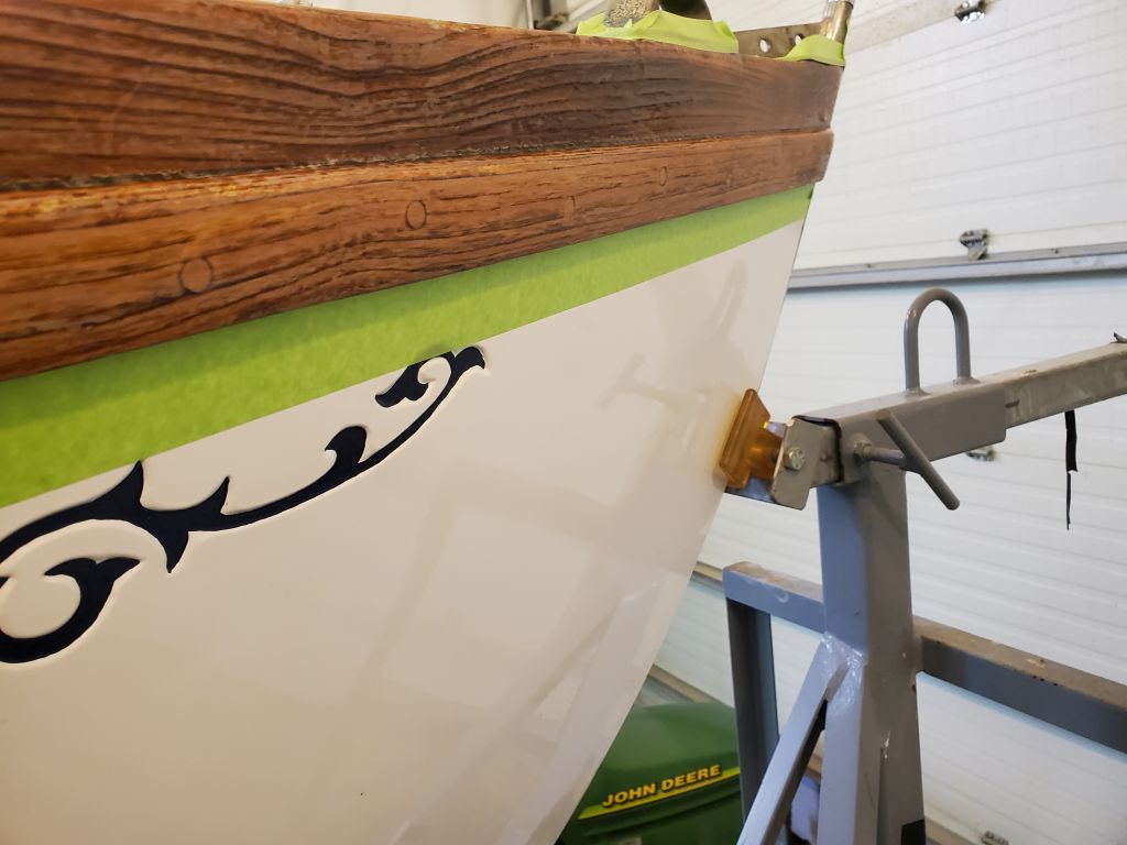
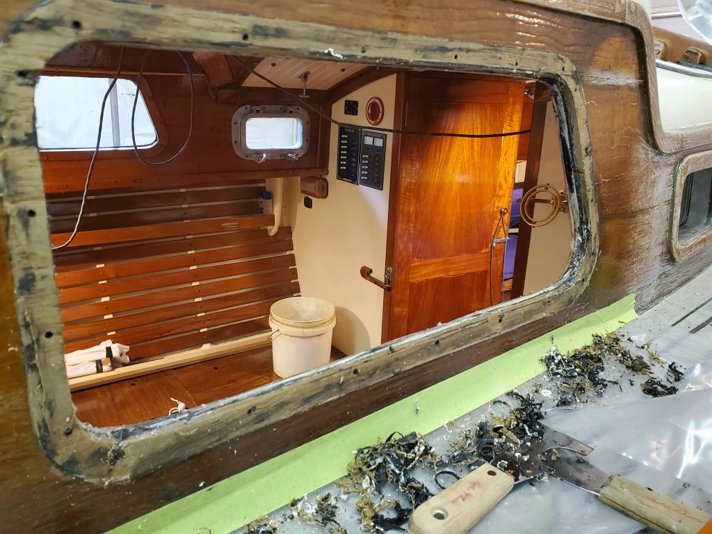
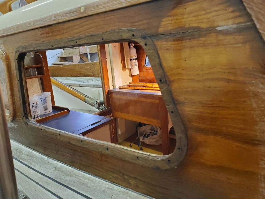
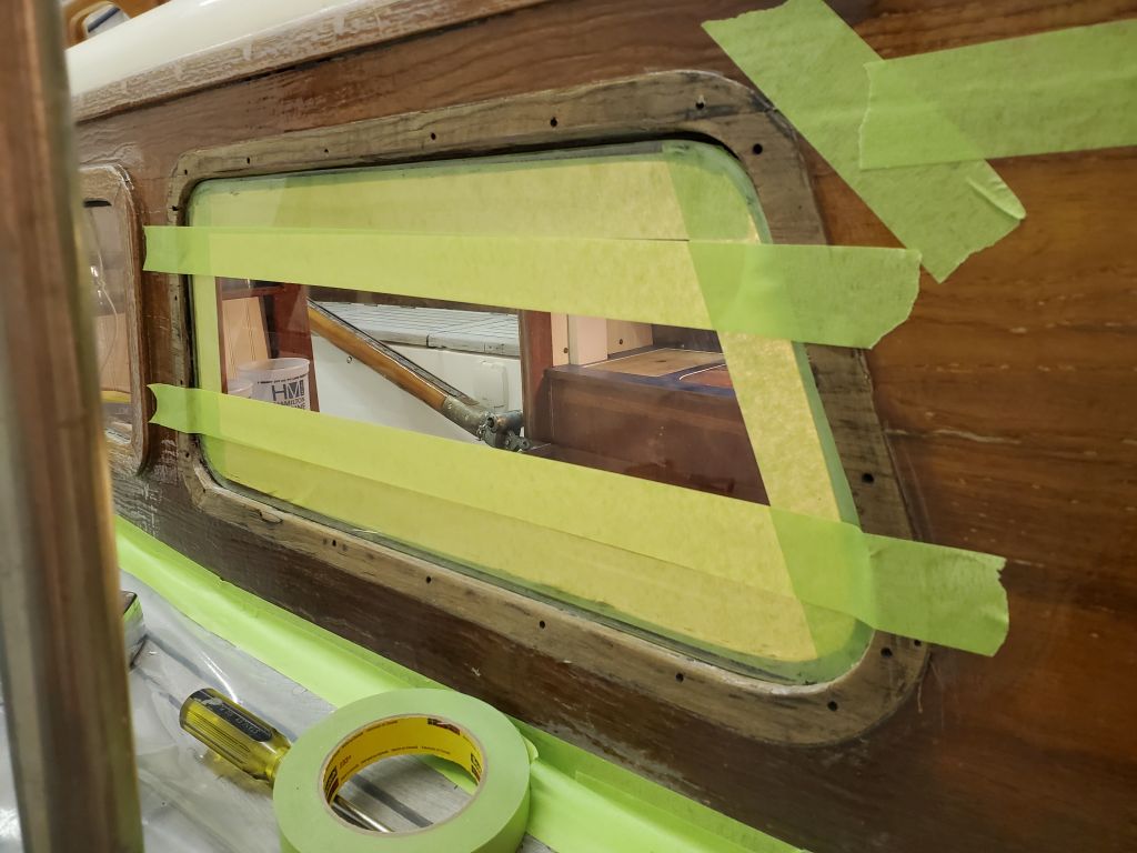
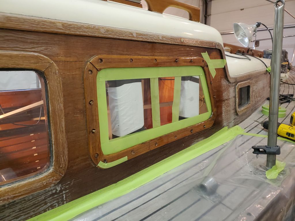
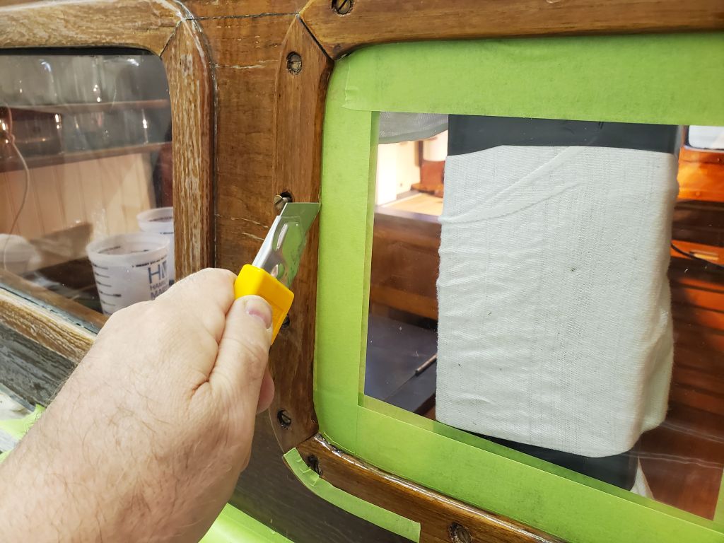
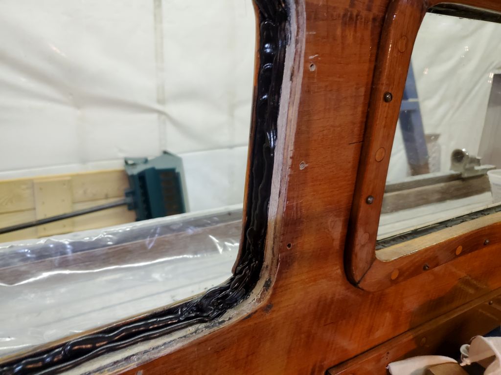
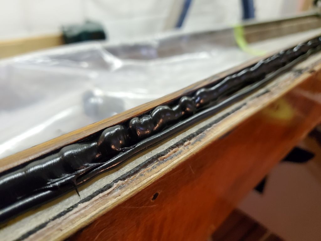
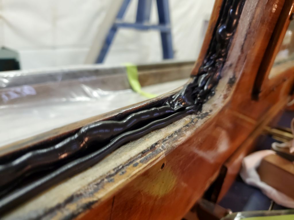
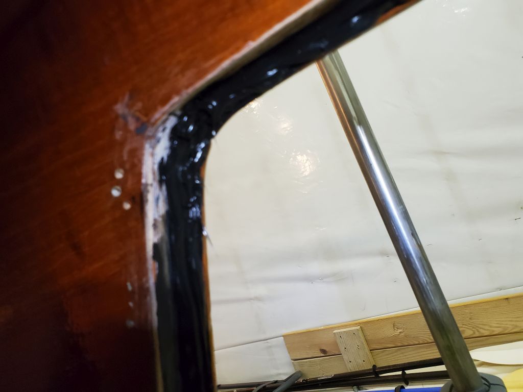
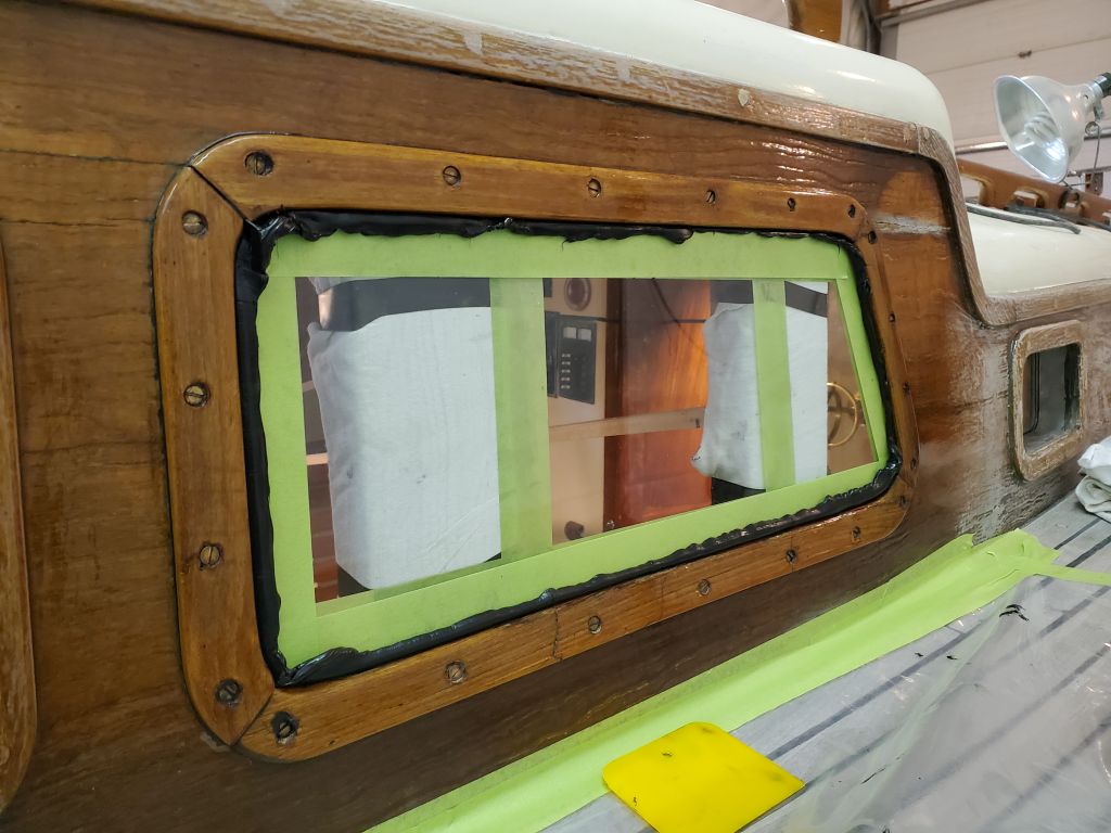
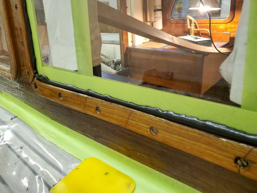
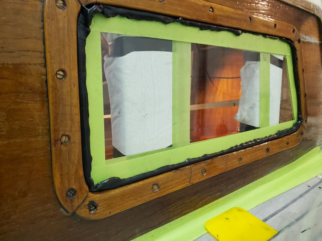
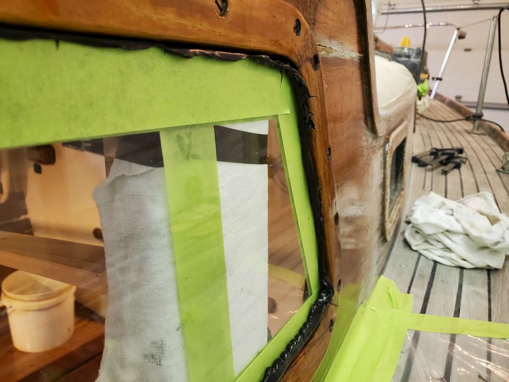
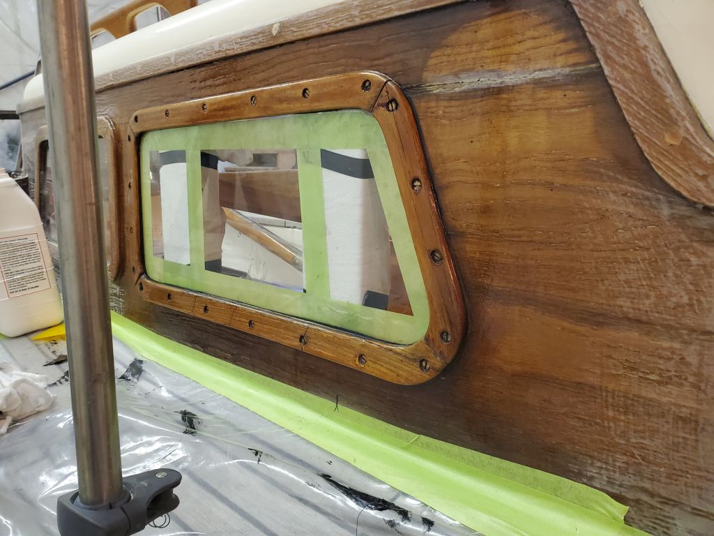
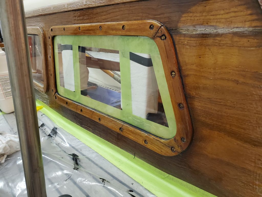
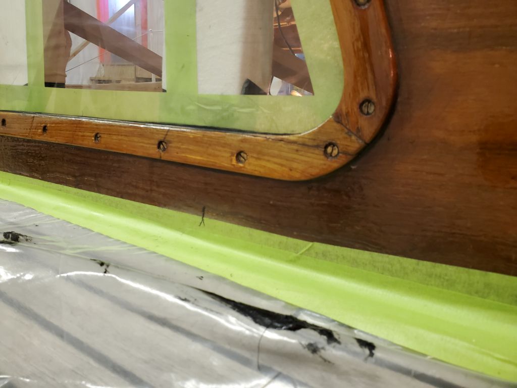
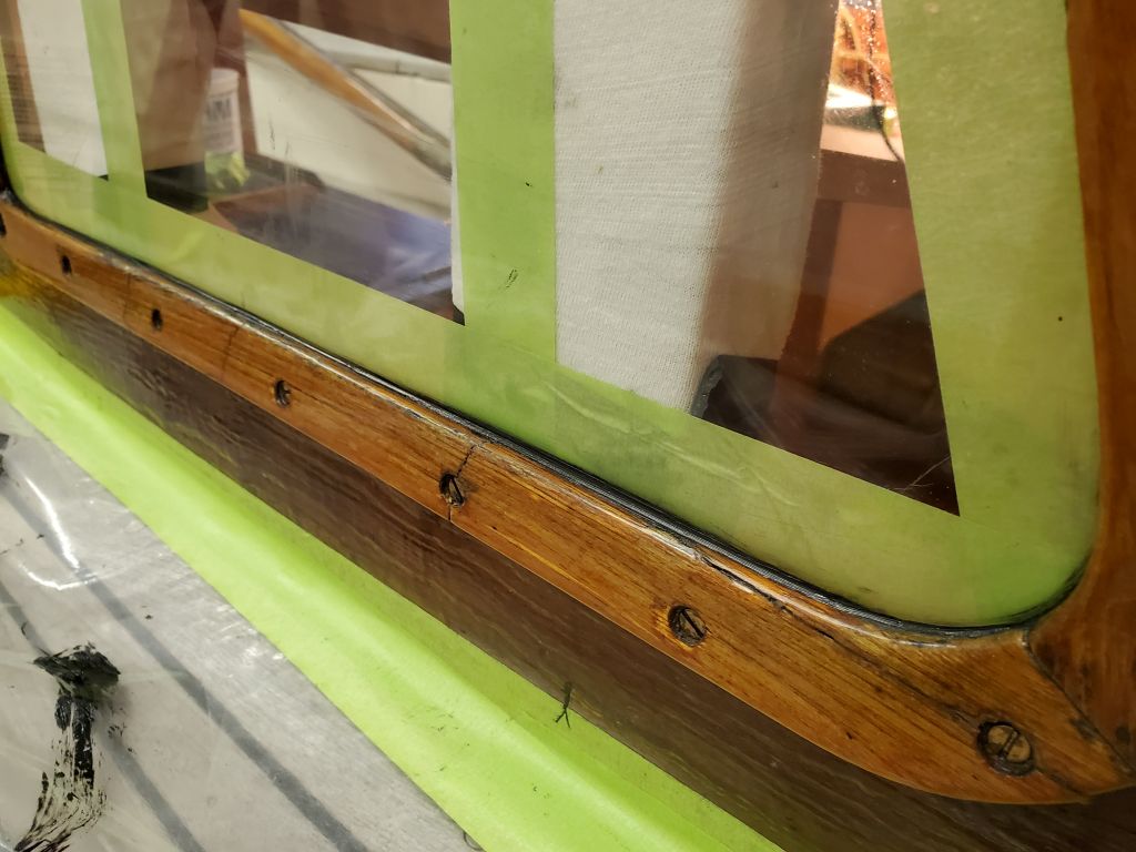
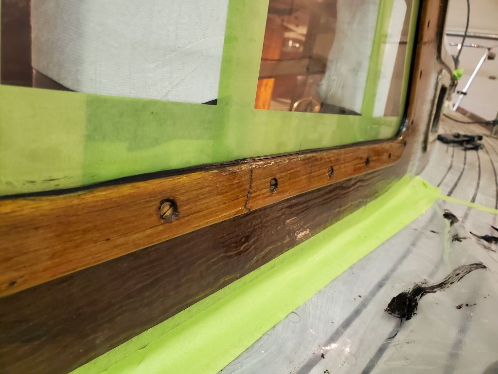
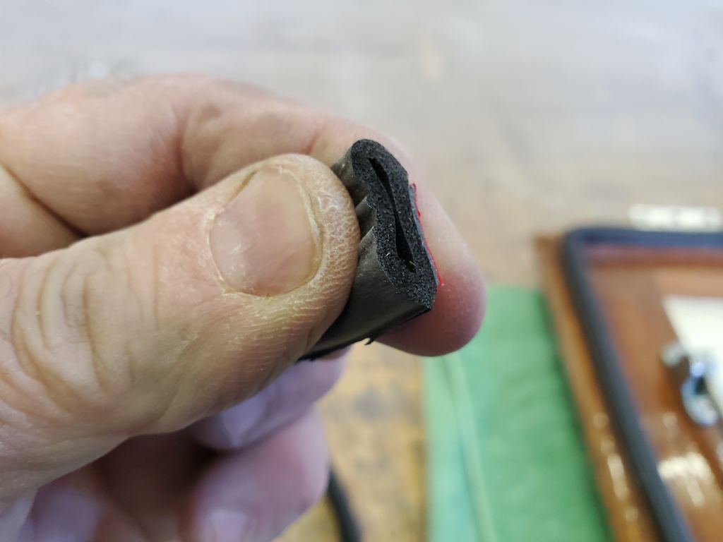
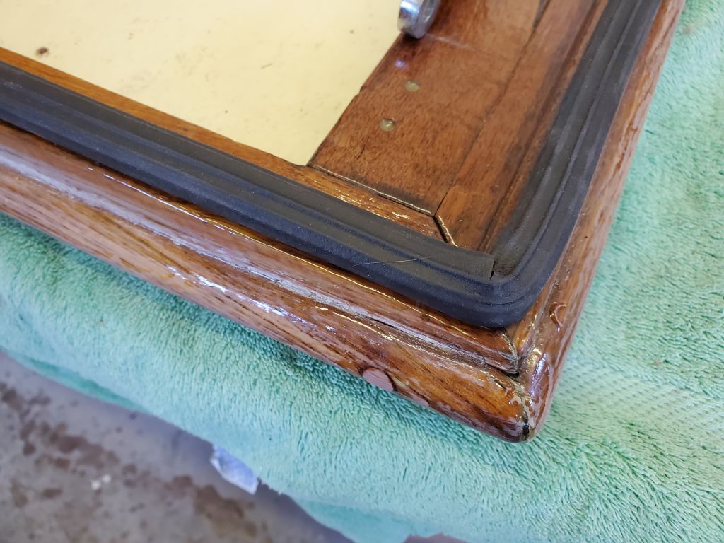
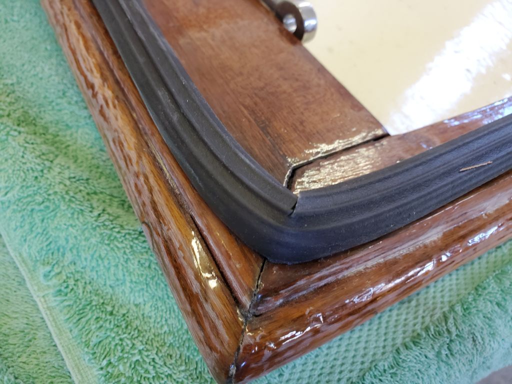
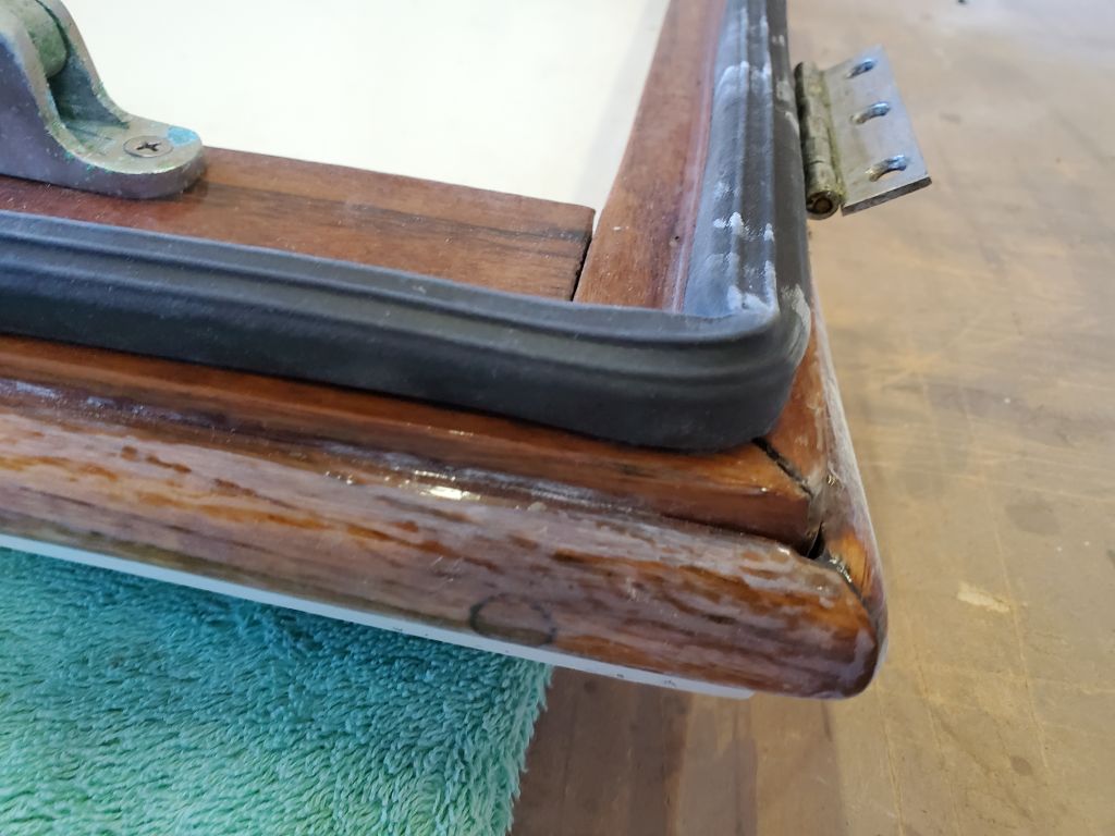
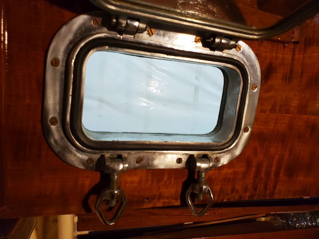
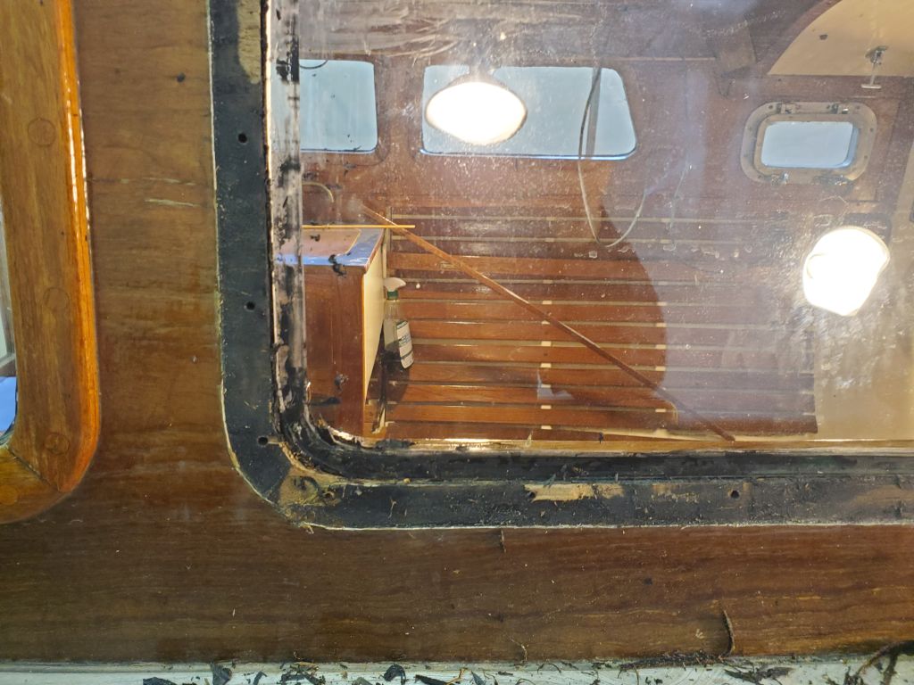
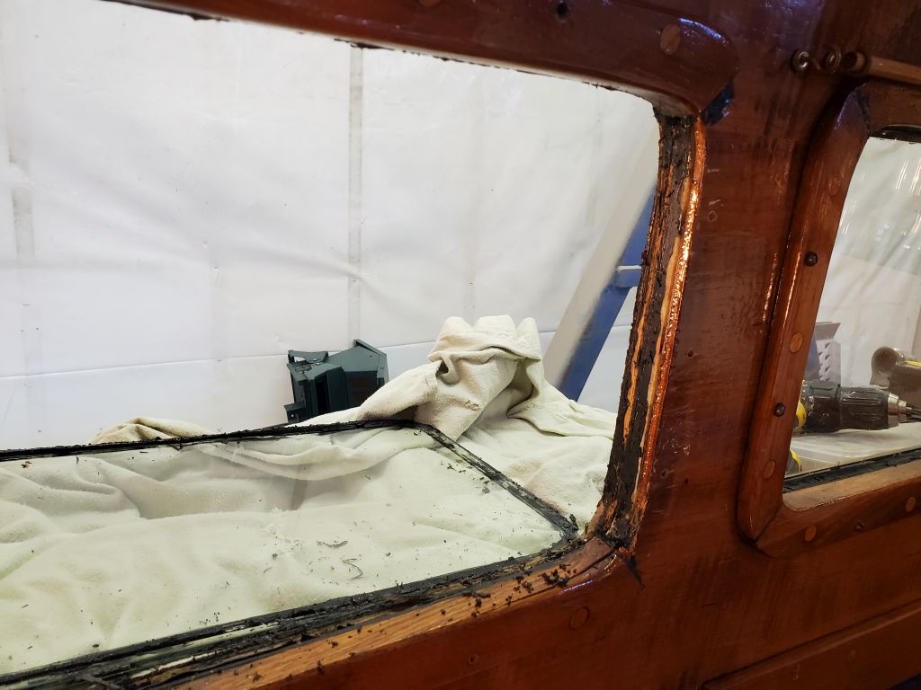
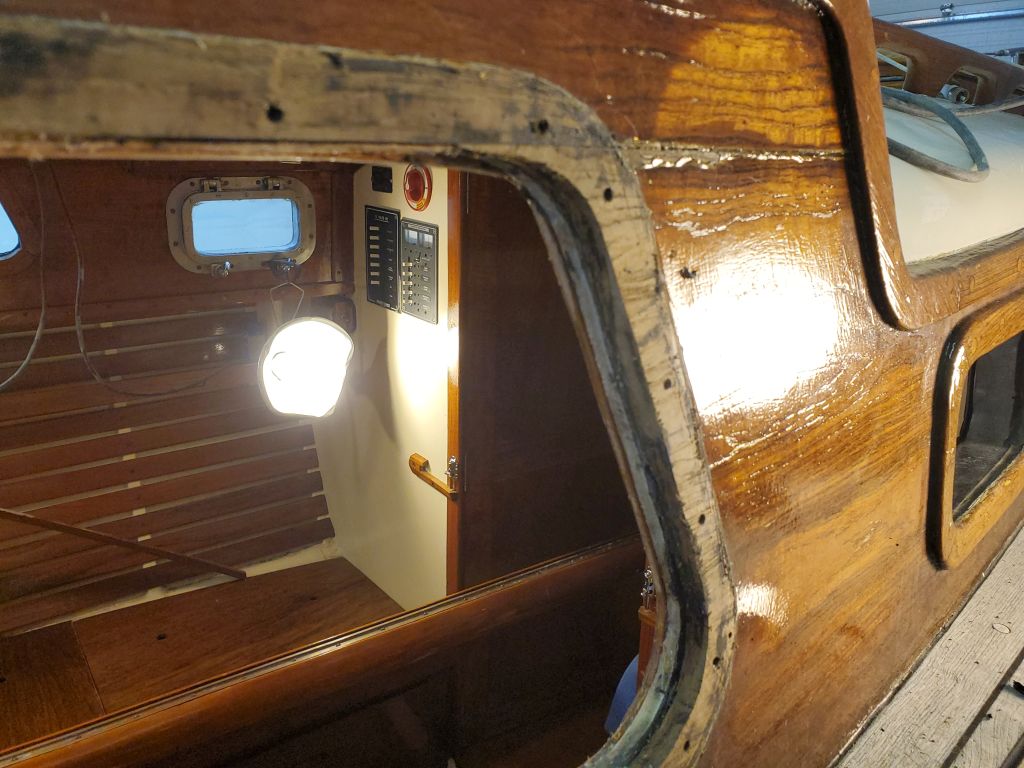
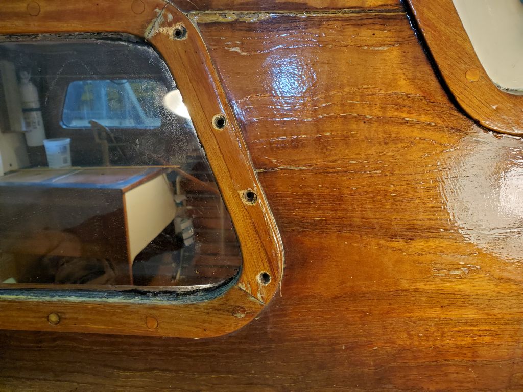
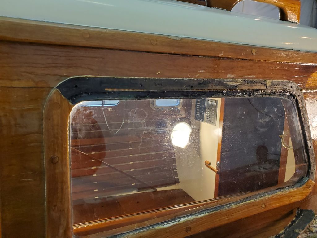
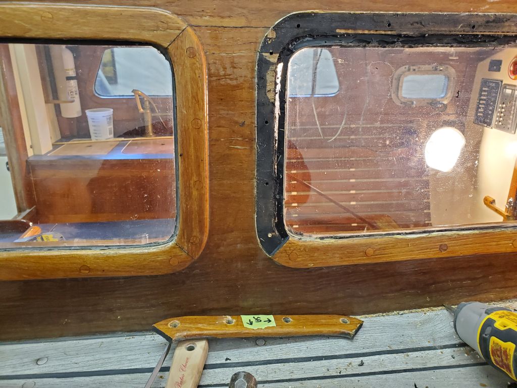
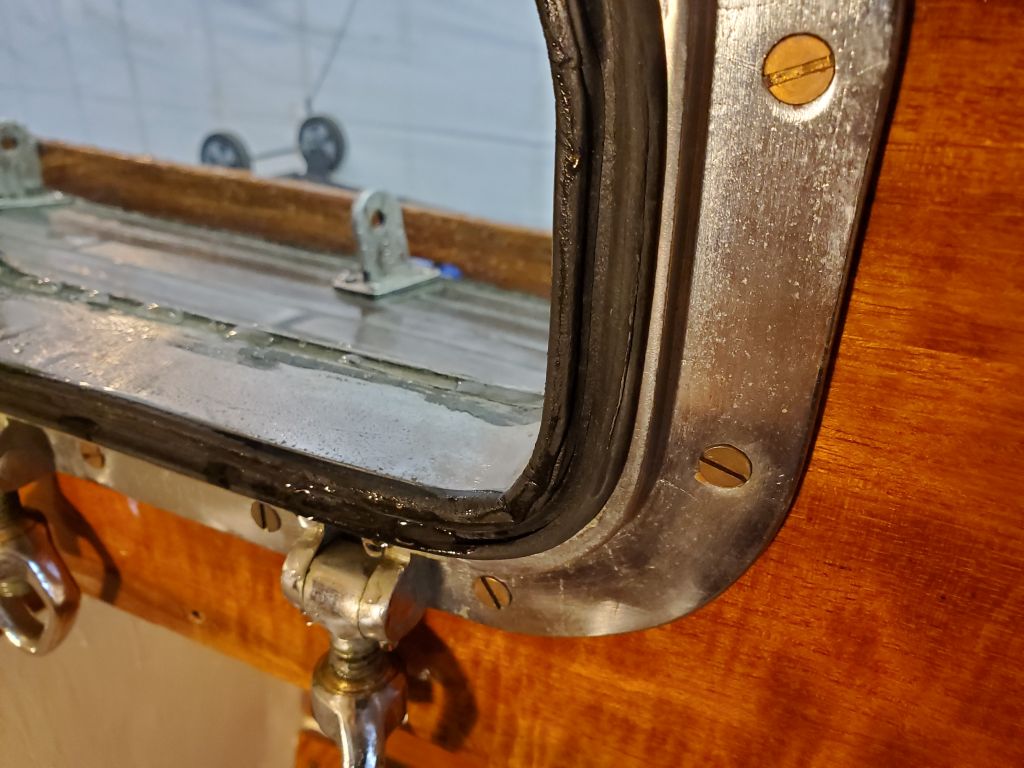
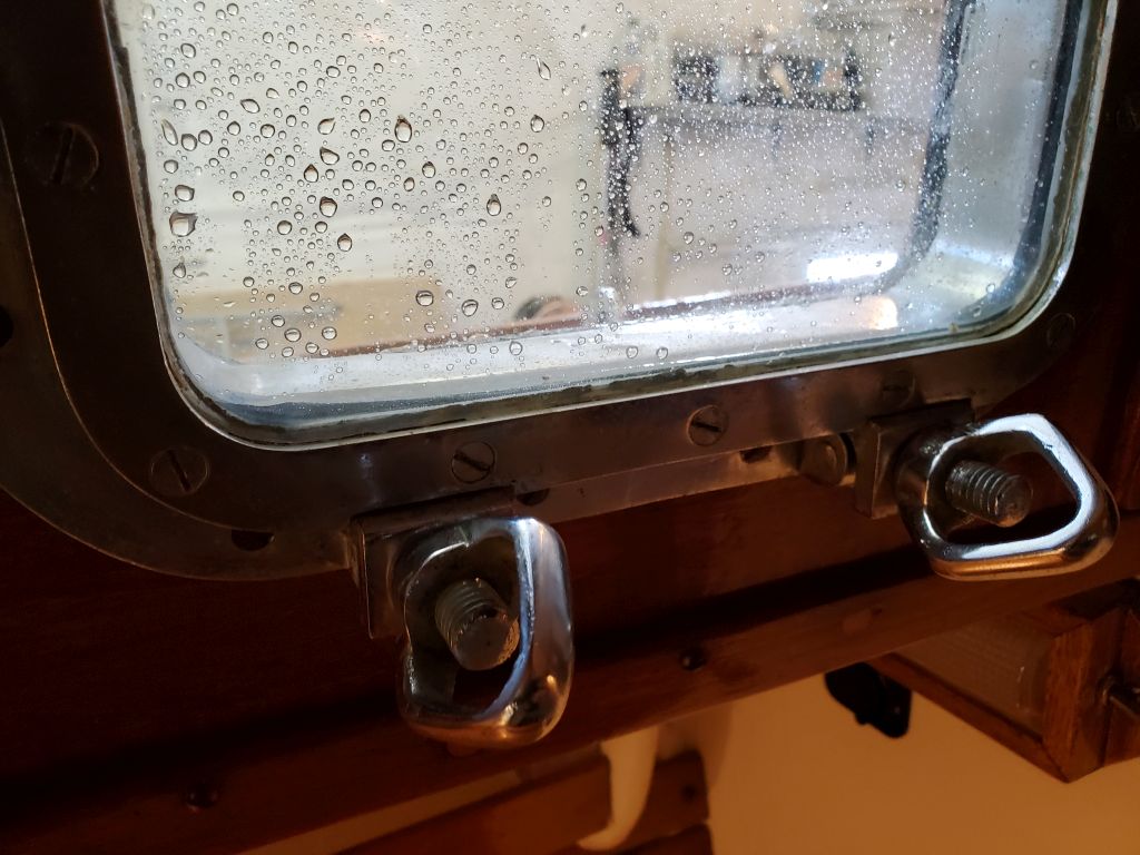
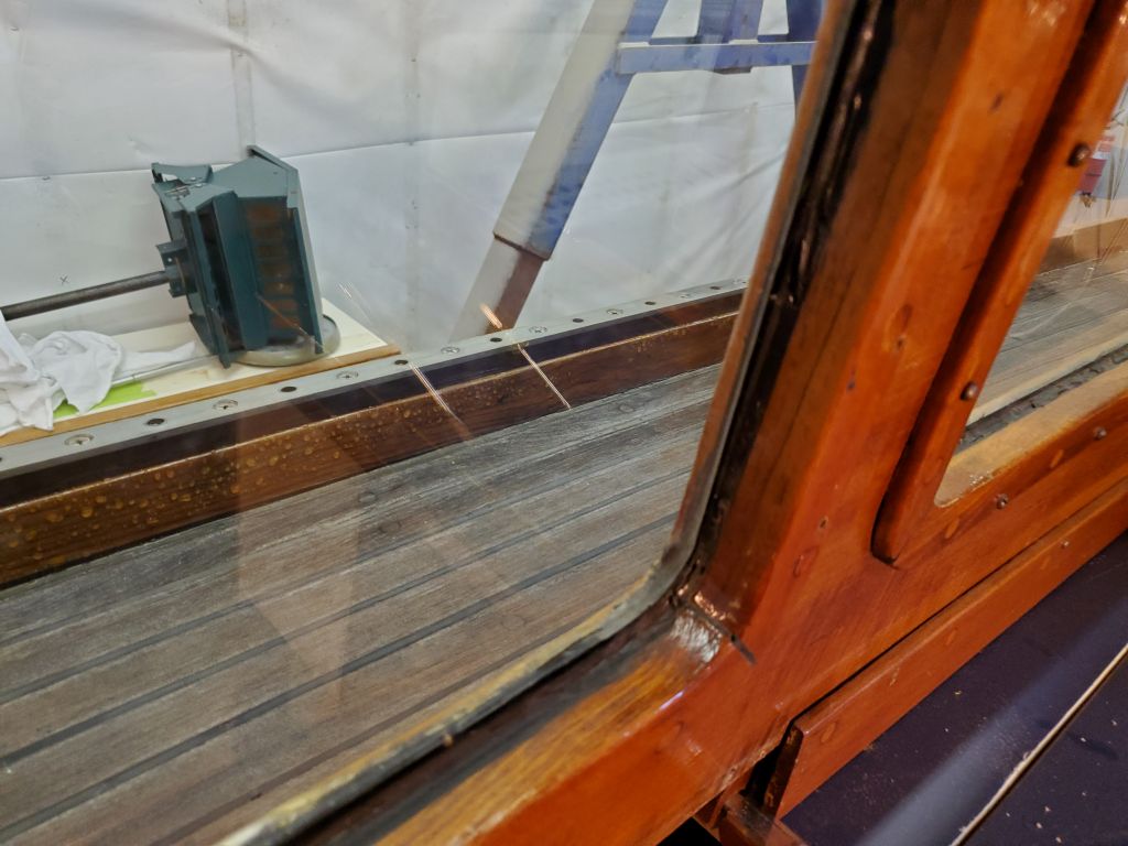
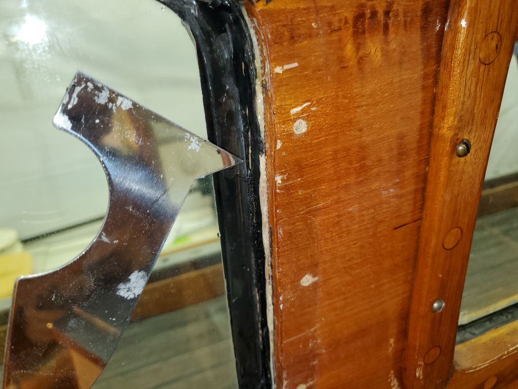
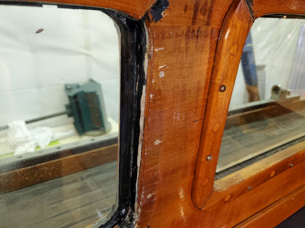
Satisfied with the clamping setup and the overall arrangement, I removed the braces and glass, trimmed the masking tape, and then, from outside, removed the trim to prepare for bedding and final installation.  Then, one piece at a time, I applied heavy beads of sealant and fastened the trim down securely all the way around, ensuring good sealant squeeze-out in all areas.  I cleaned up the excess sealant around the outside of the trim.  I used Sikaflex 295UV sealant.

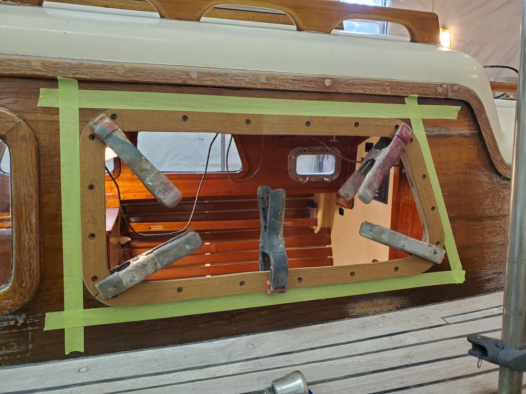
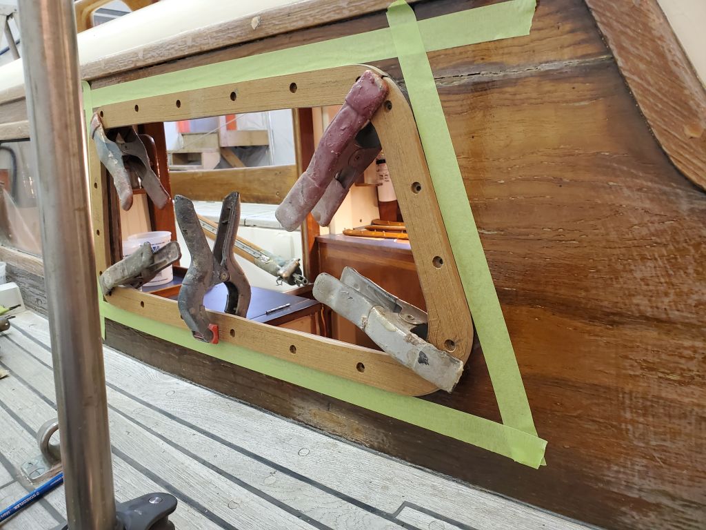
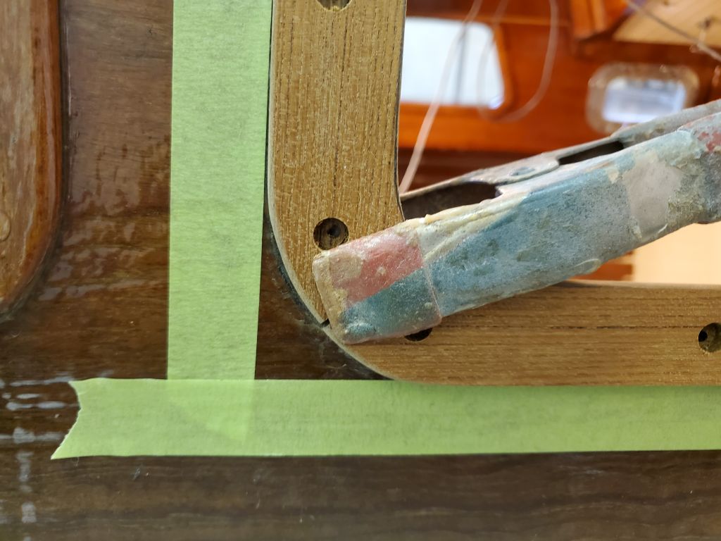
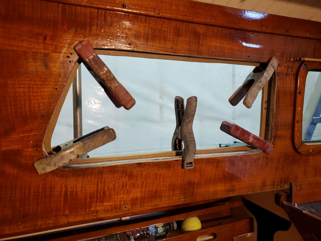
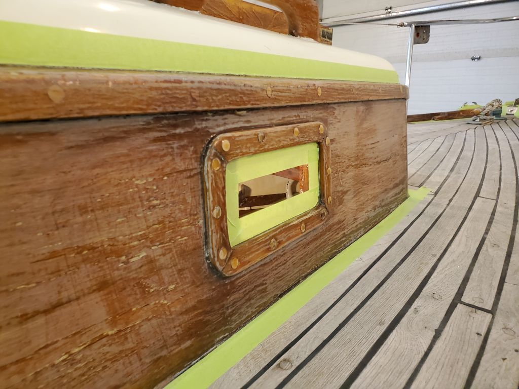
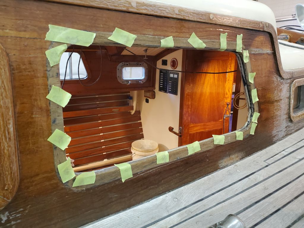
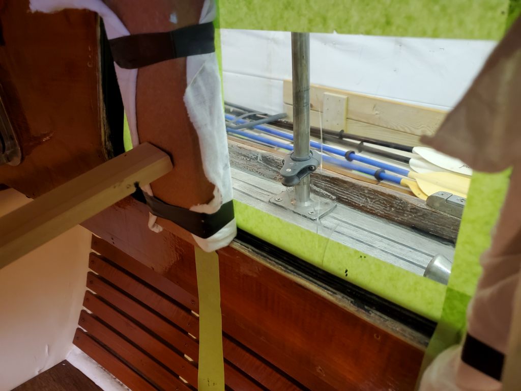
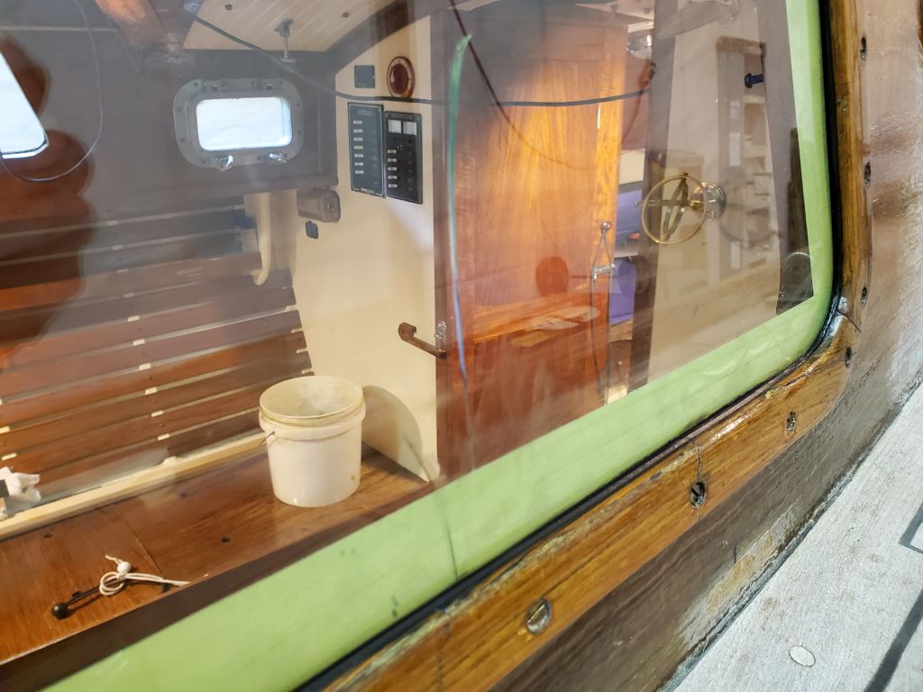
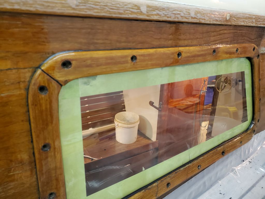
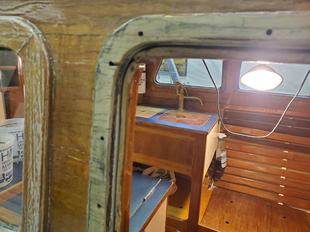
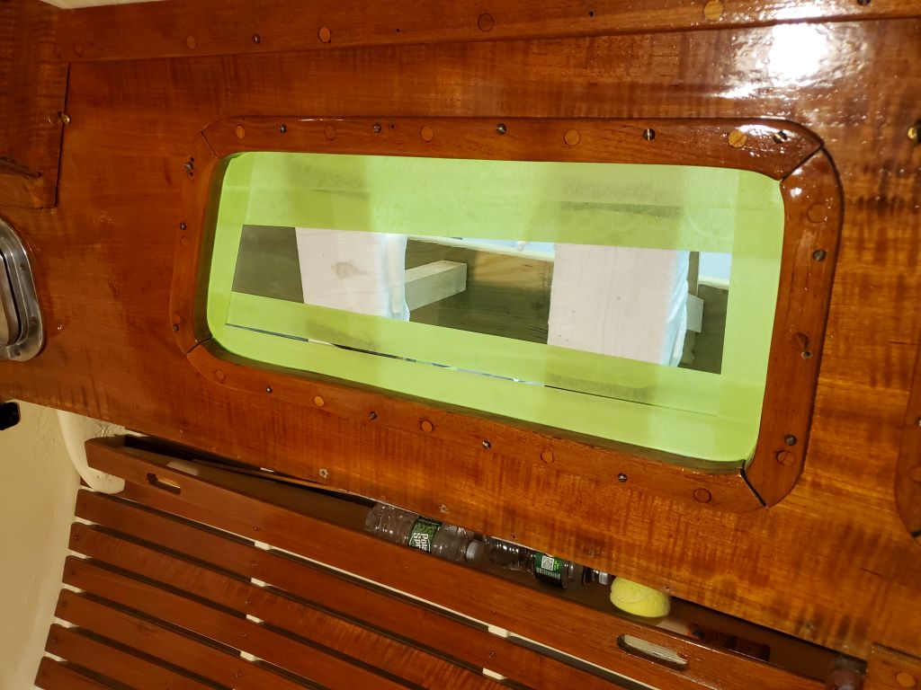
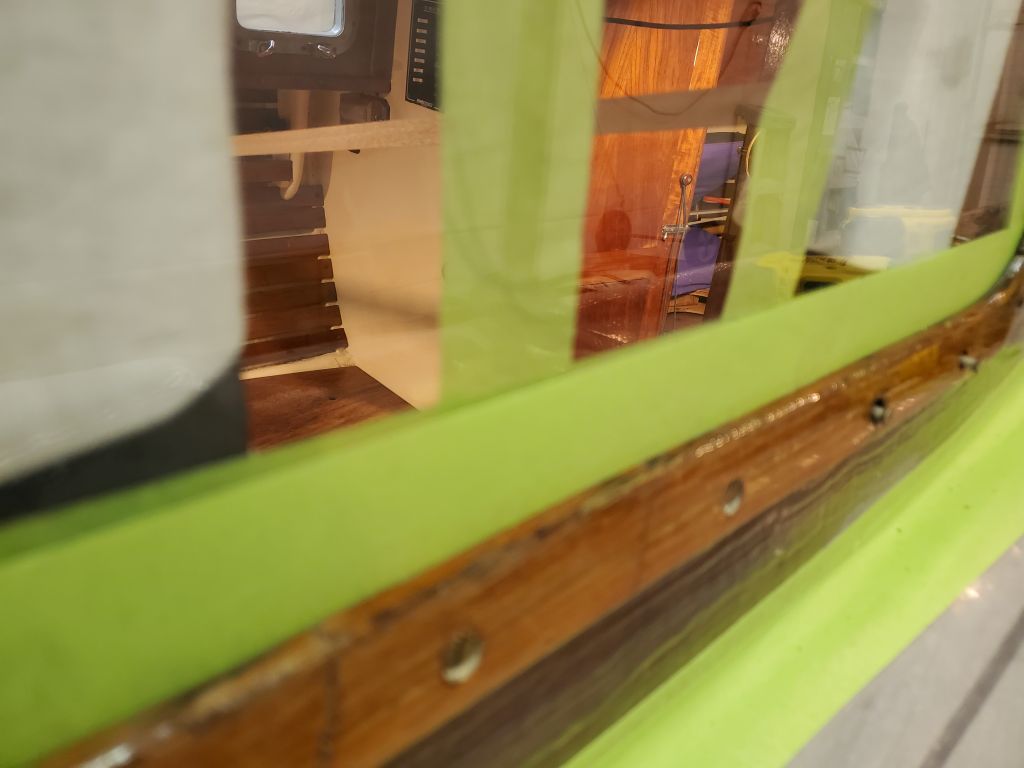
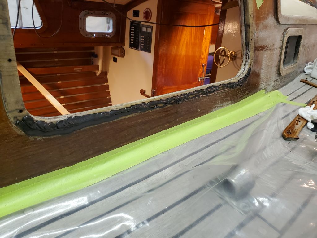
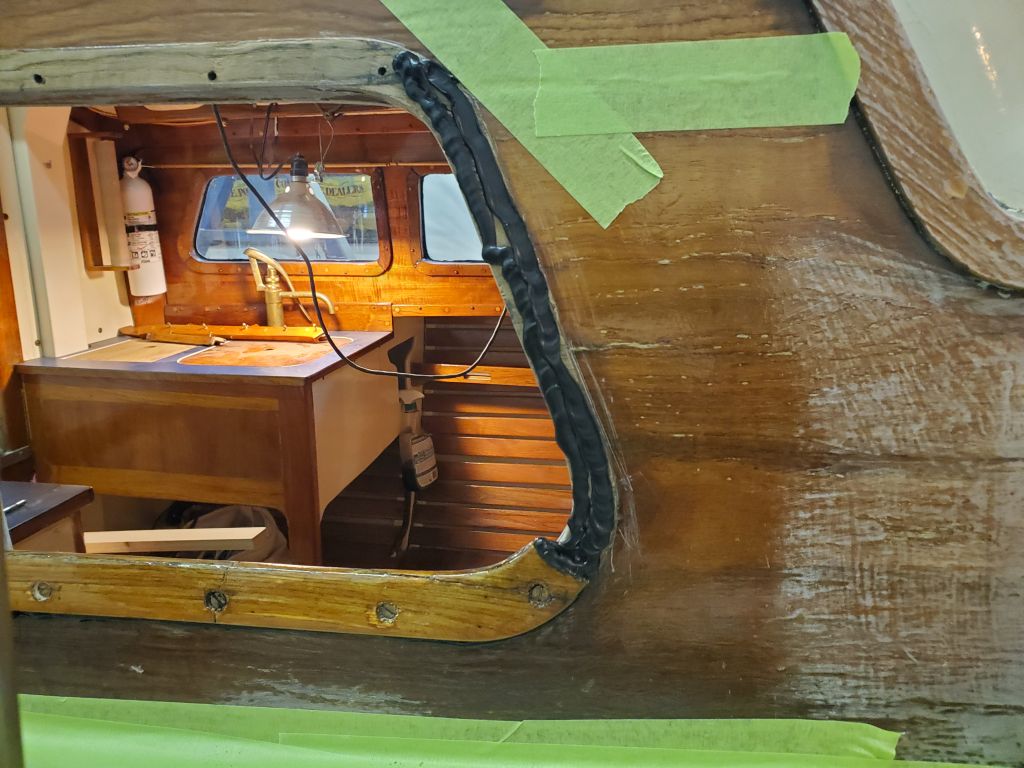
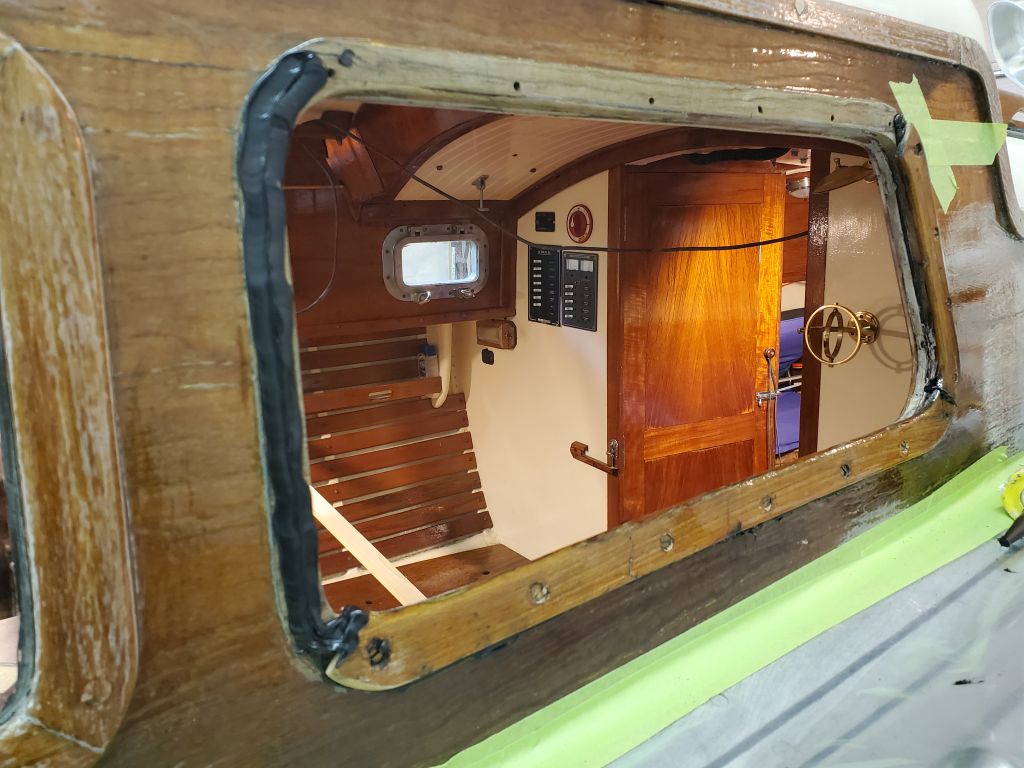
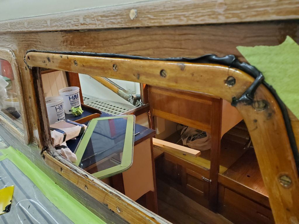
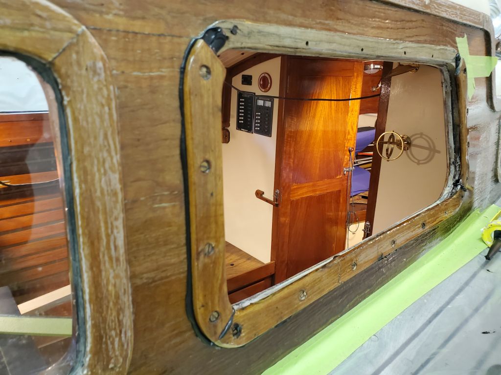
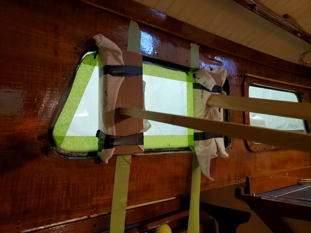
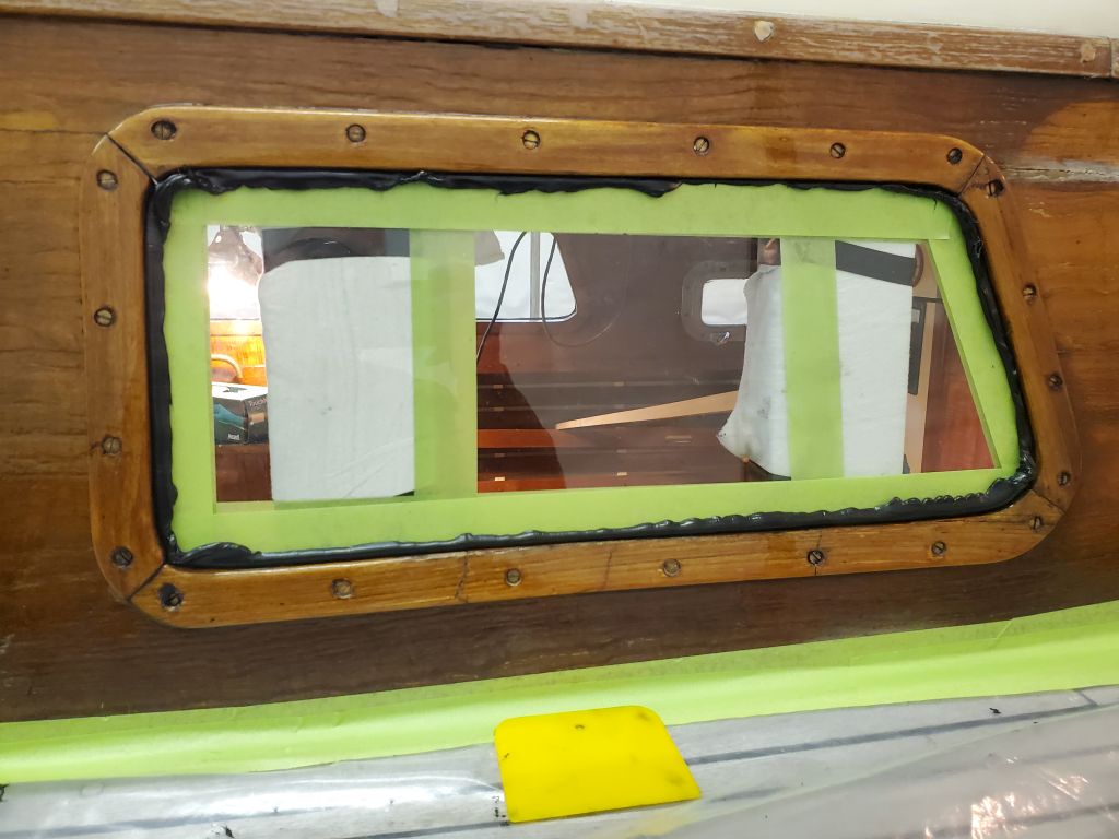
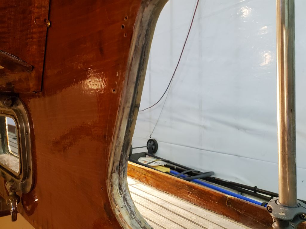
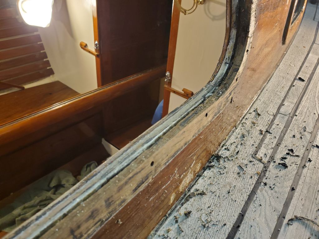
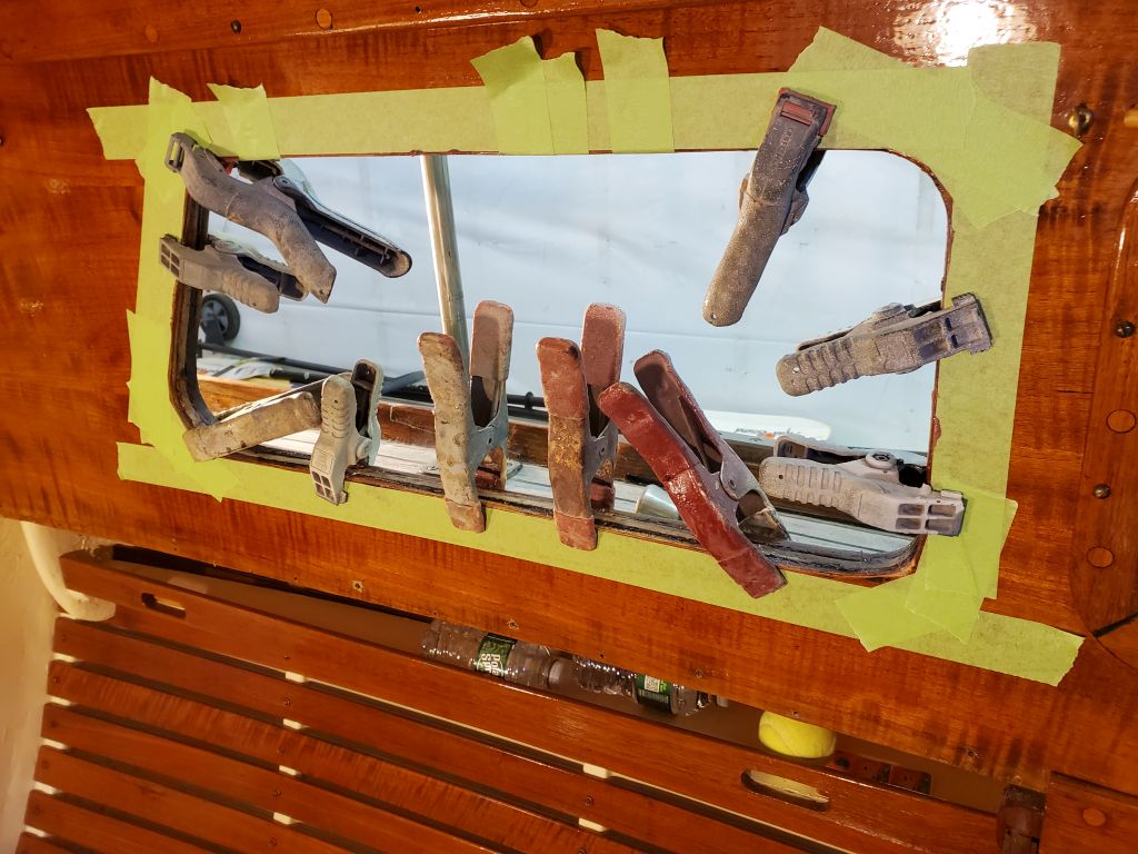
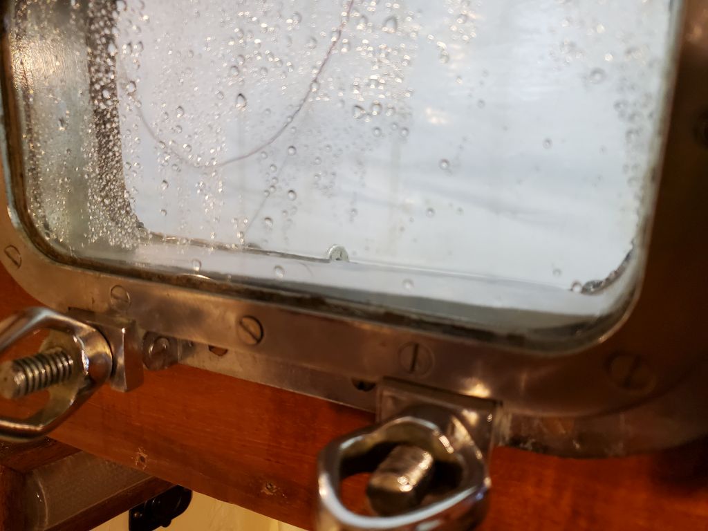
Inside the boat, I applied more heavy beads of sealant to the inside face of the trim and around the opening, then pressed the glass into place, applying hand pressure till I felt that it had evenly pressed into the sealant all around.  I installed some masking tape to hold it, then the braces running across the cabin.

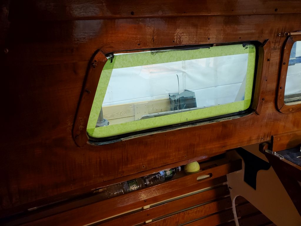
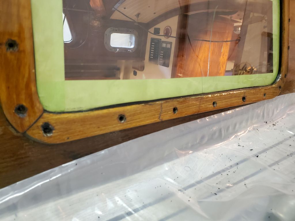
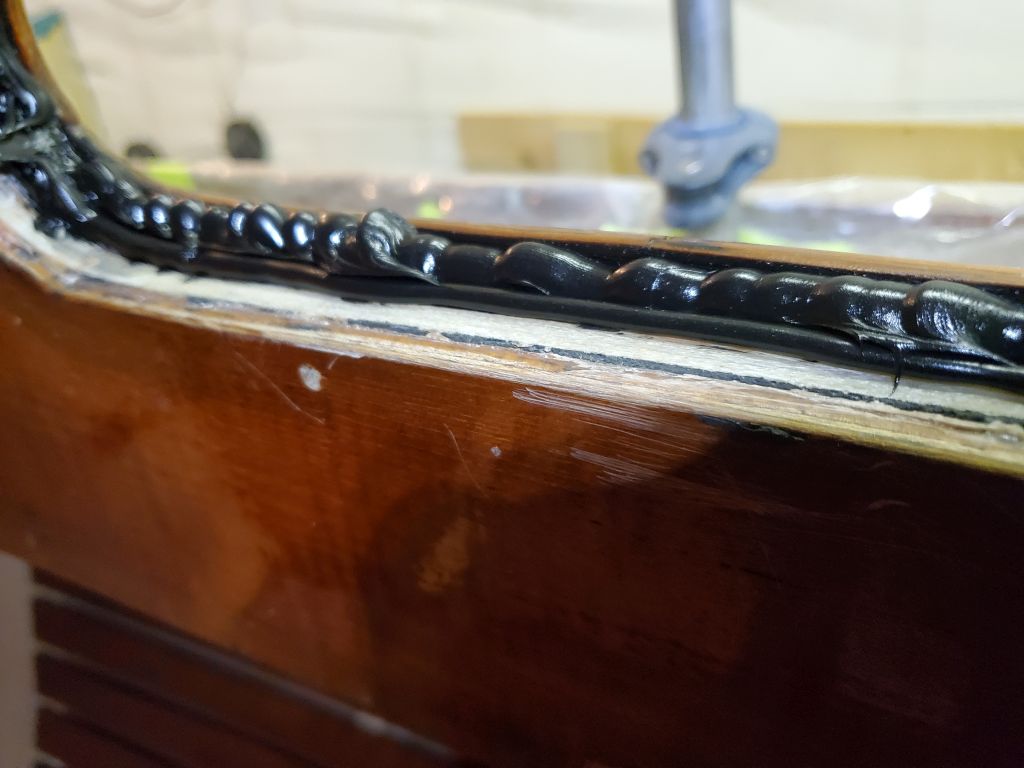
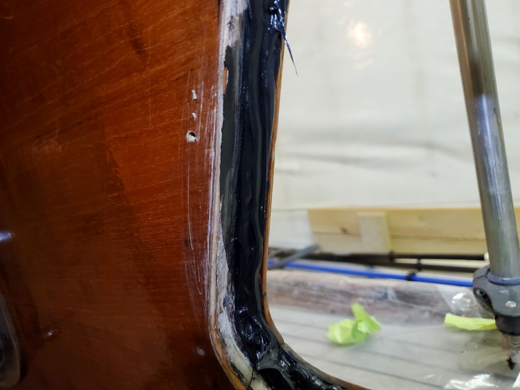
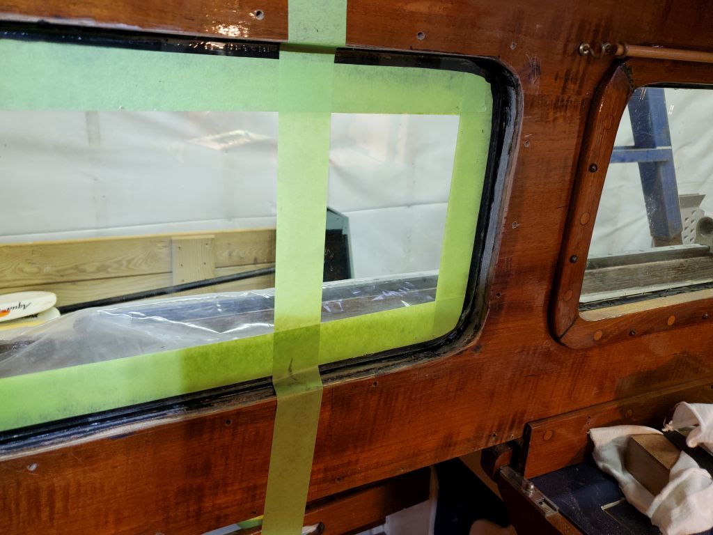
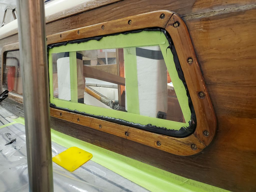
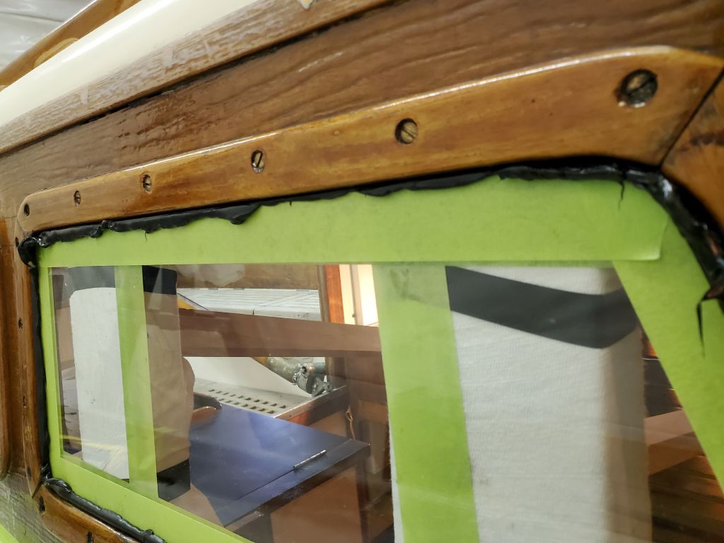
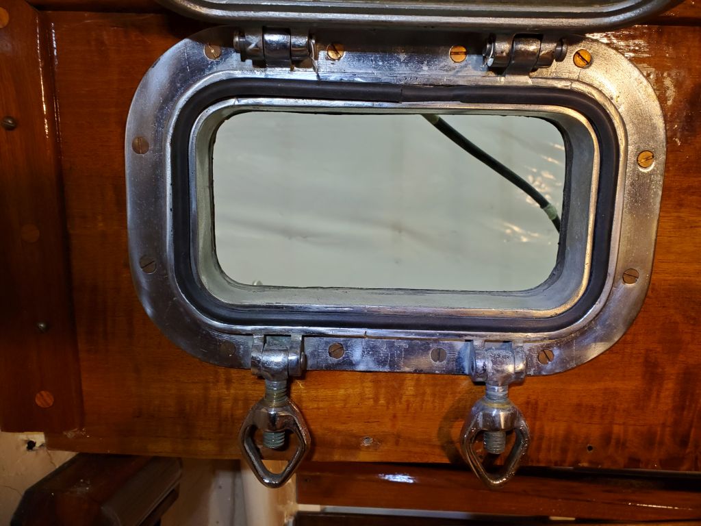
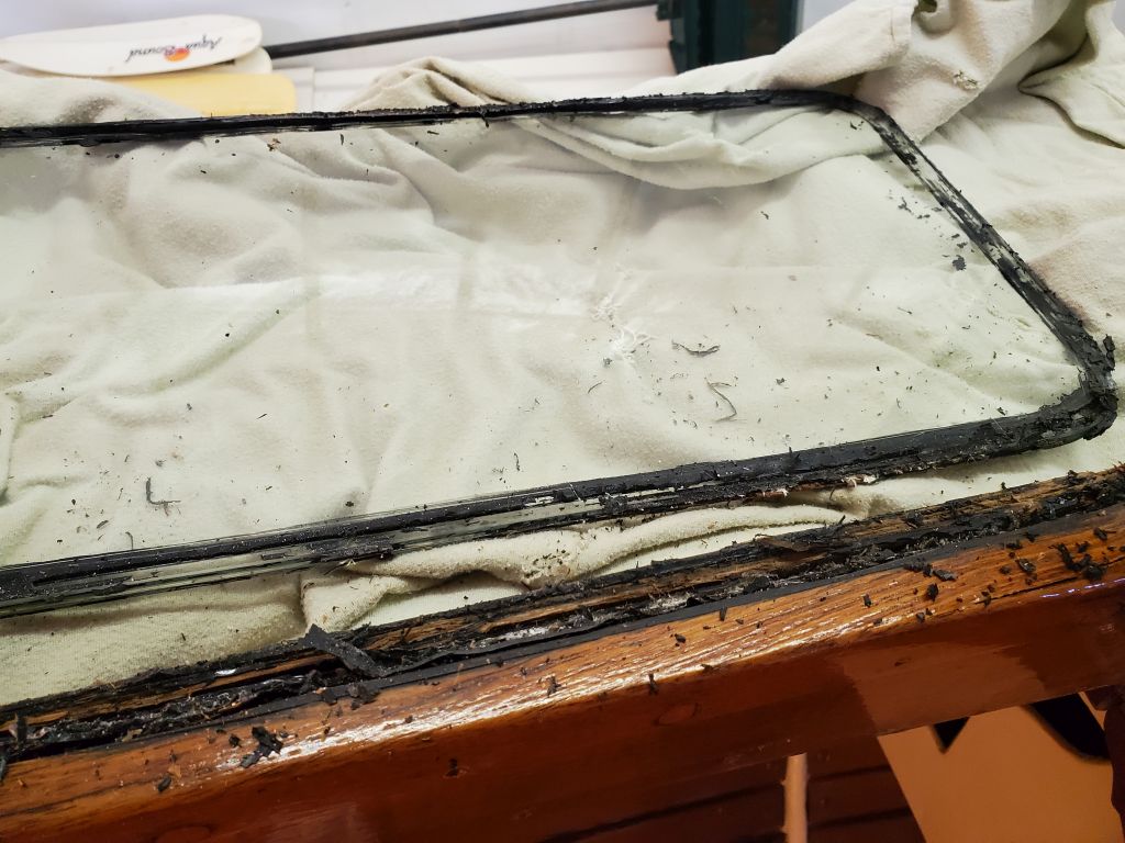
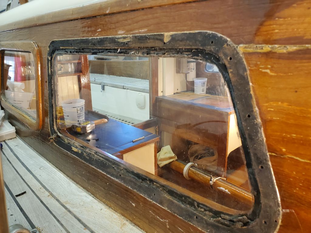
Outside, the squeezeout was excellent all the way around the glass.

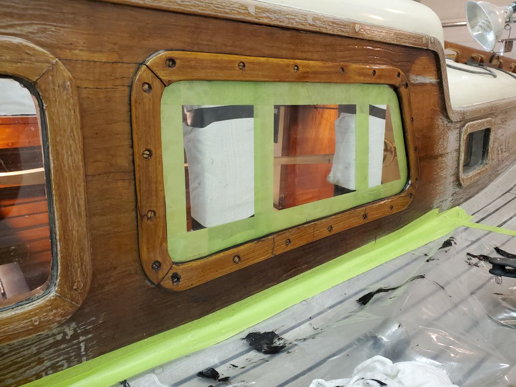
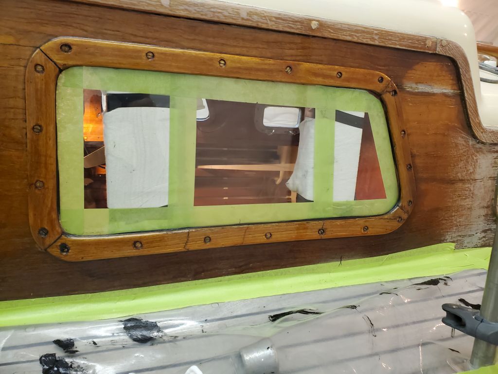
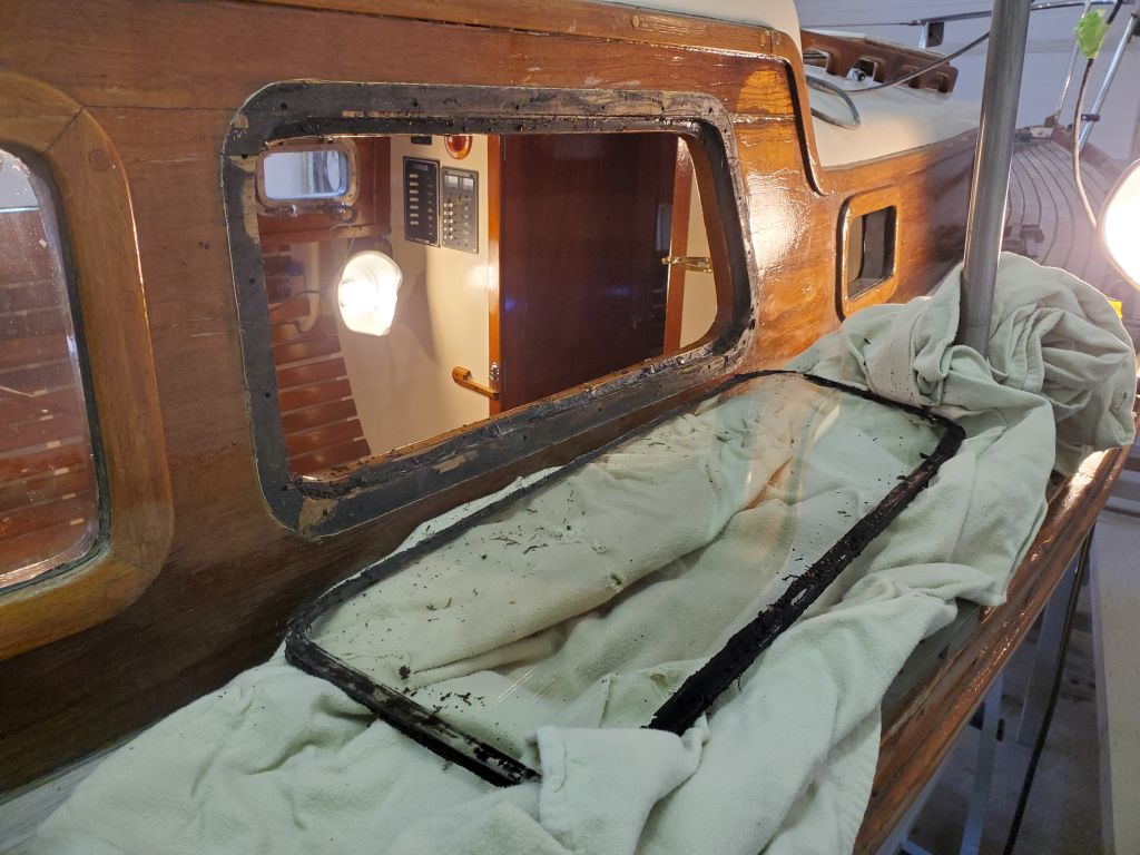
To finish up for now, I cleaned up the excess sealant from the glass and pulled the exterior masking tape.  I’d leave the interior bracing in place for as long as needed to ensure the sealant cured sufficiently.

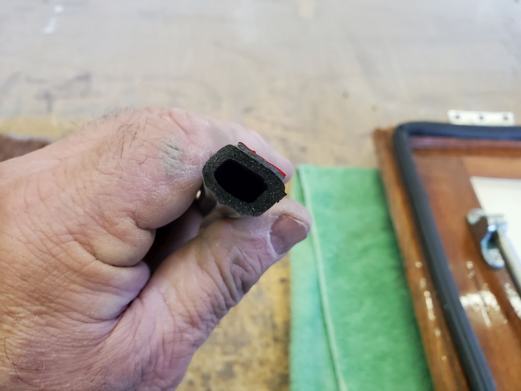
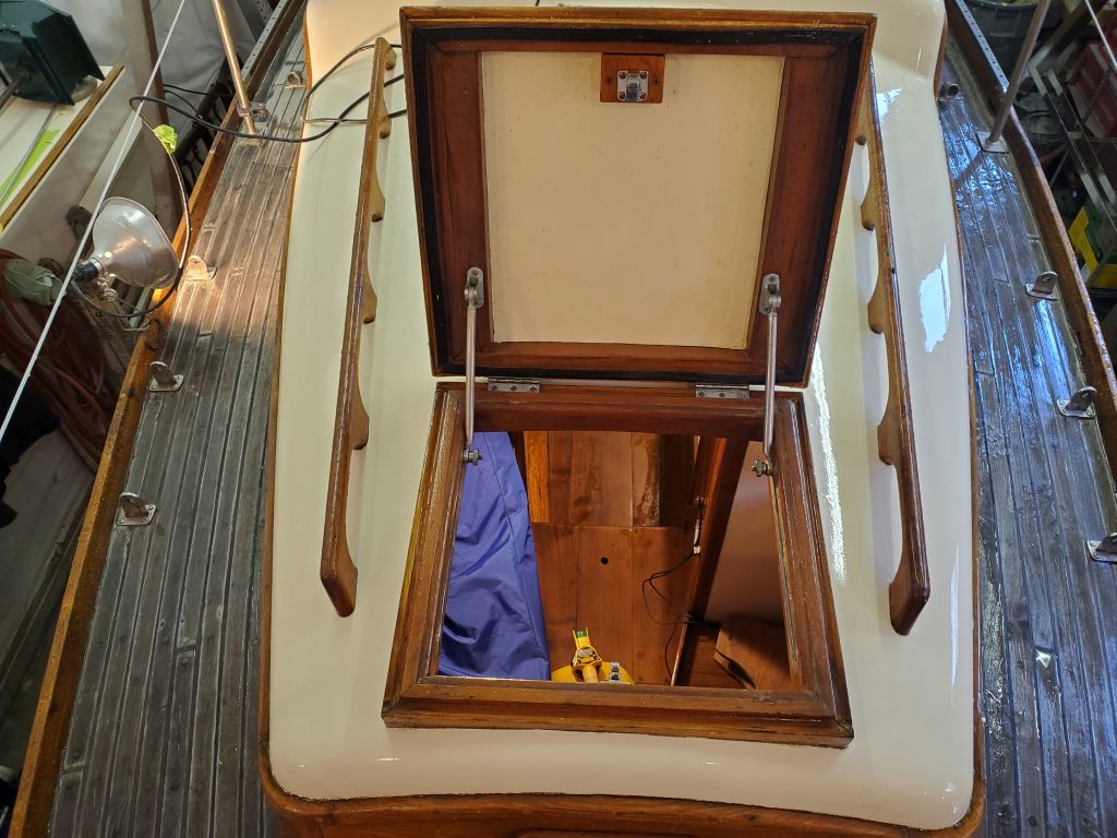
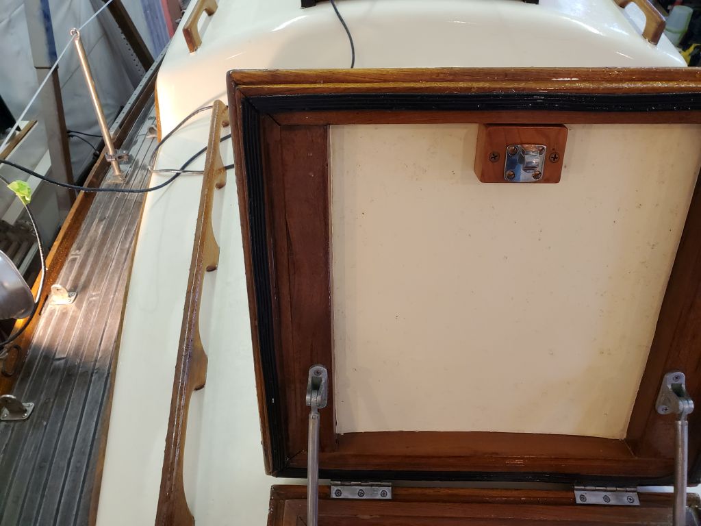
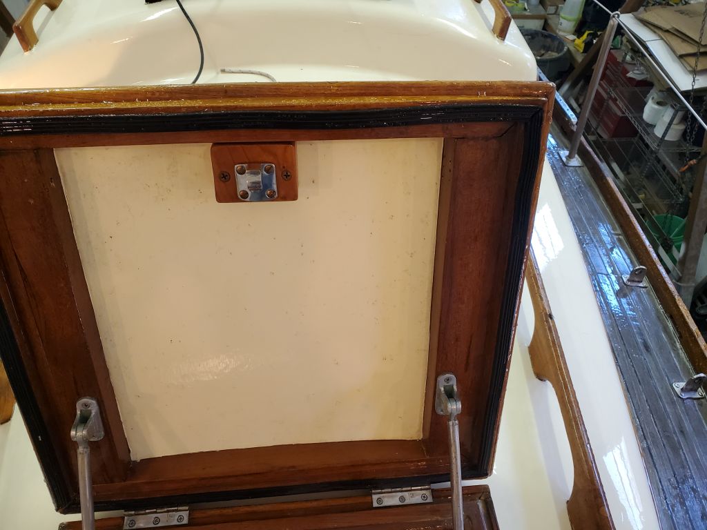
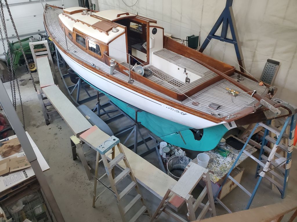
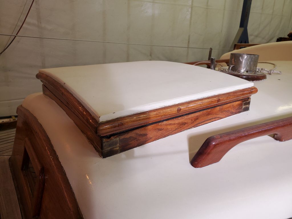
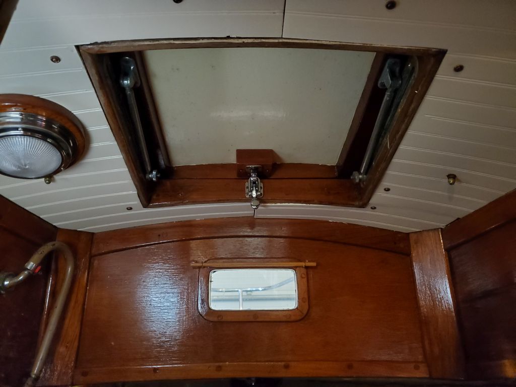
In other works, I reinstalled the forward hatch to check the fit of the new seal and to determine if the clamping block needed adjustment.  The seal seemed to work well, but when I attempted to engage the hold-down clamp, the screws pulled out of the top of the hatch, apparently unwilling to properly dig into the holes that had worked once, during initial installation, but would not grip the screws again–but not before I determined that the hatch had seemed to pull down correctly with the pressure, as the replacement gasket was a bit taller than the old one.  So I planned to glue the block in place to hold it, and make no modifications to the height.  This would happen next time.

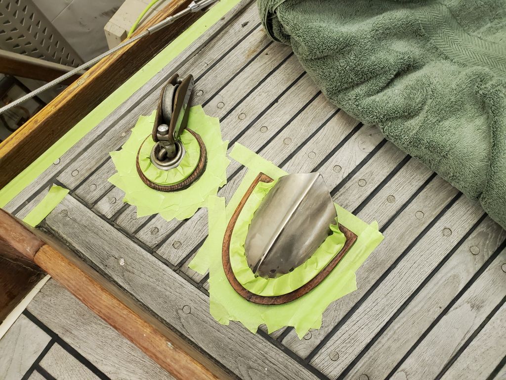
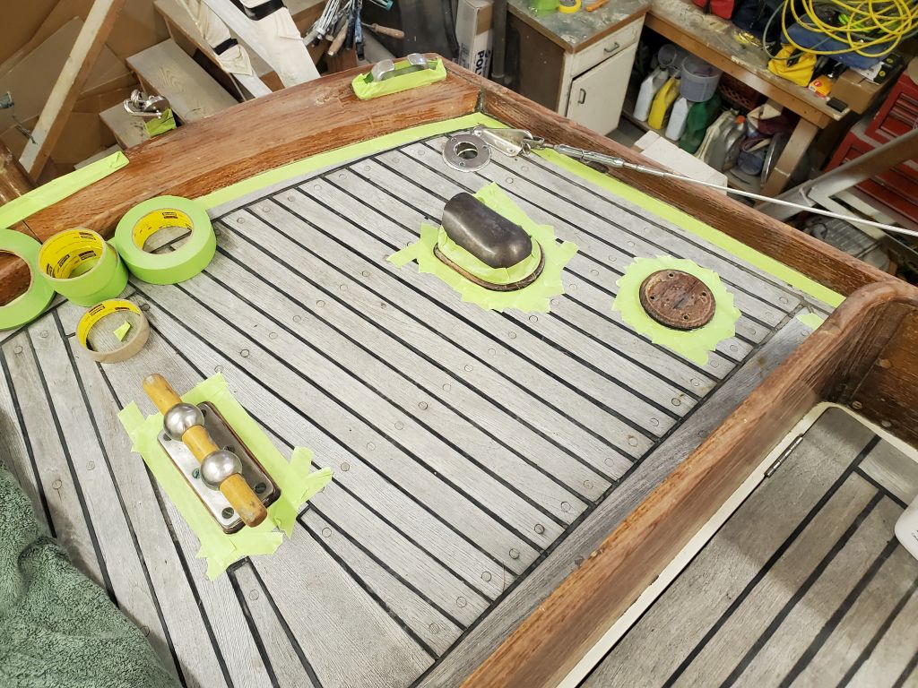
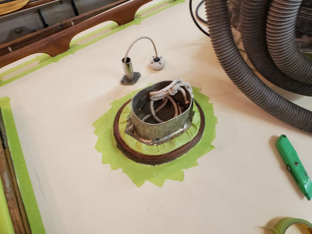
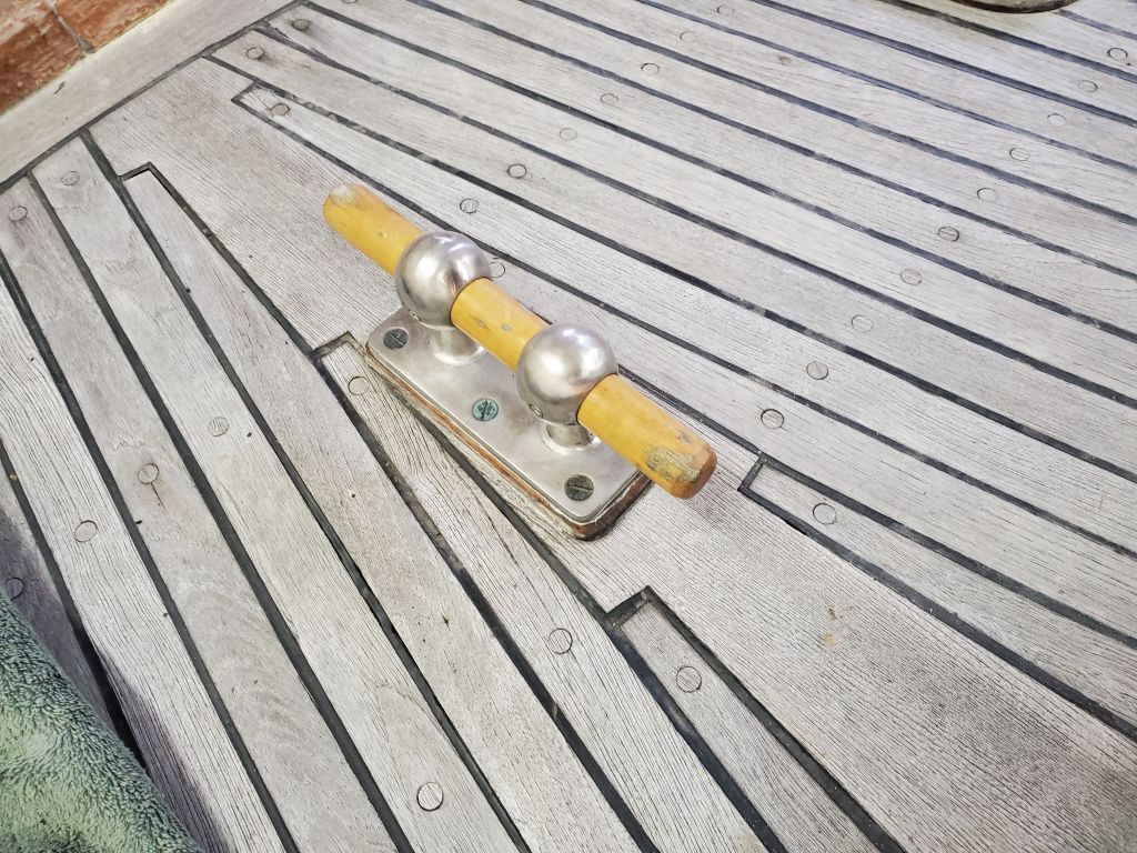
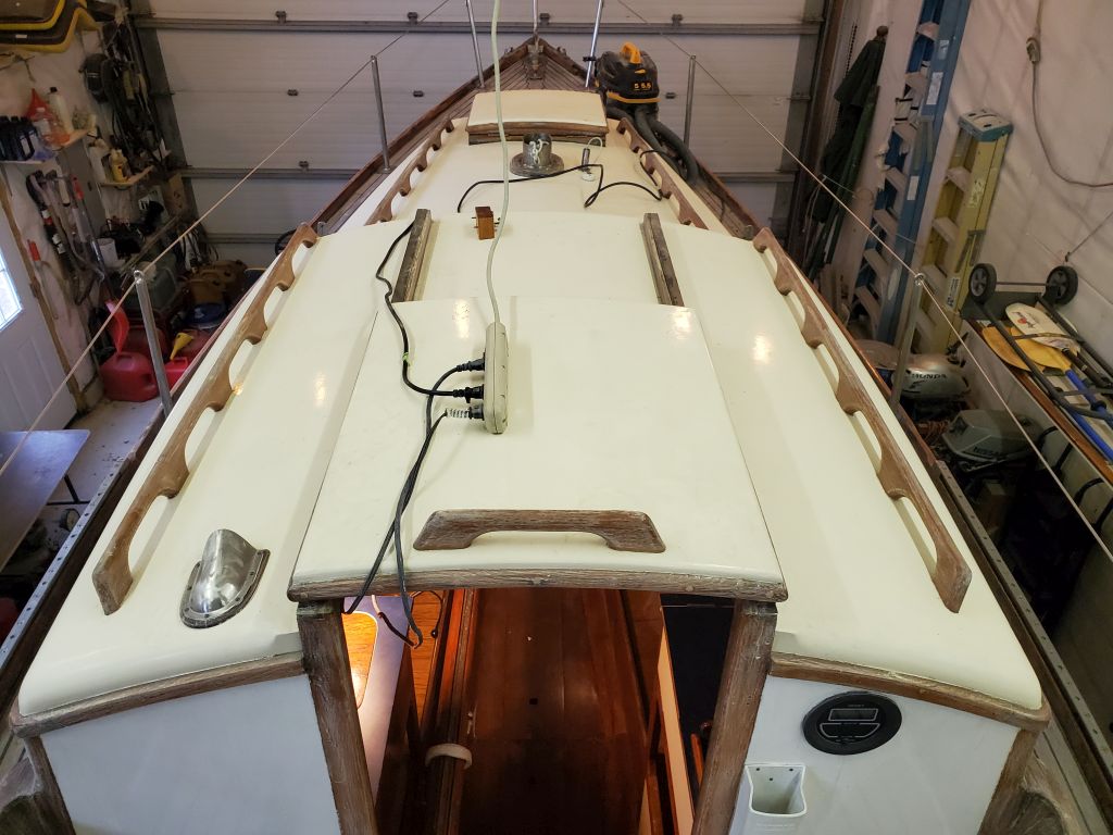
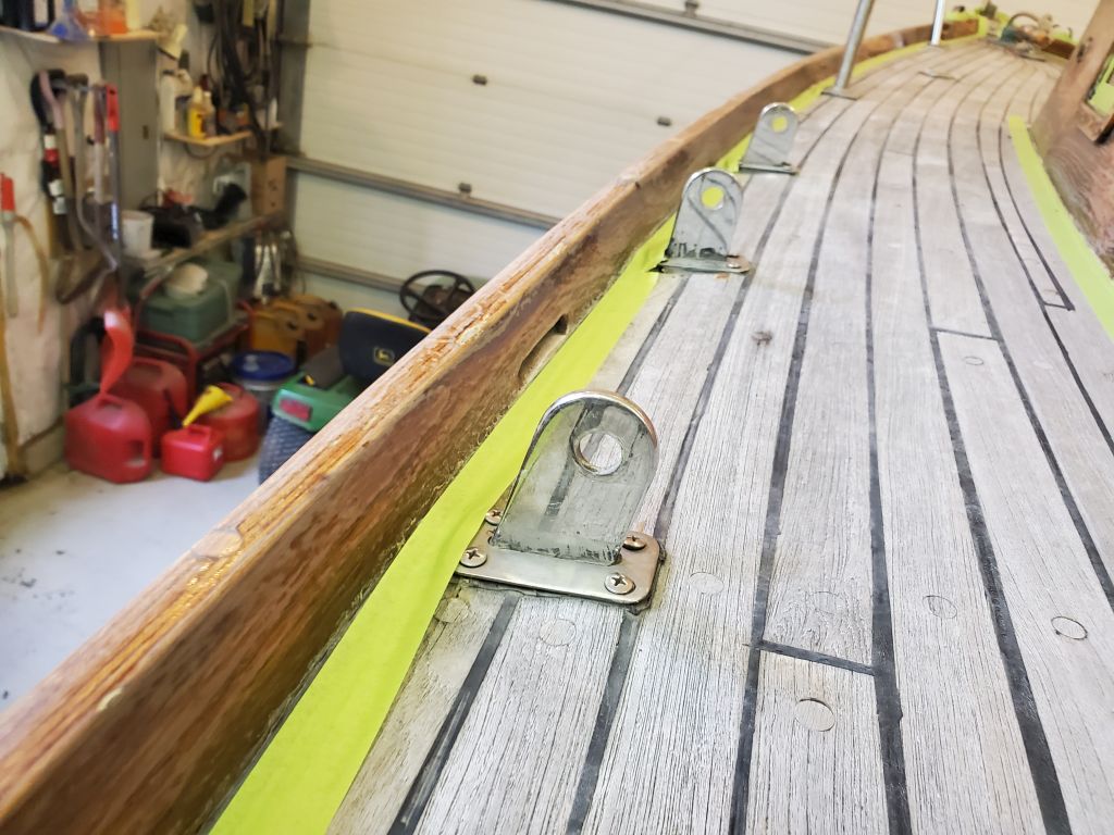
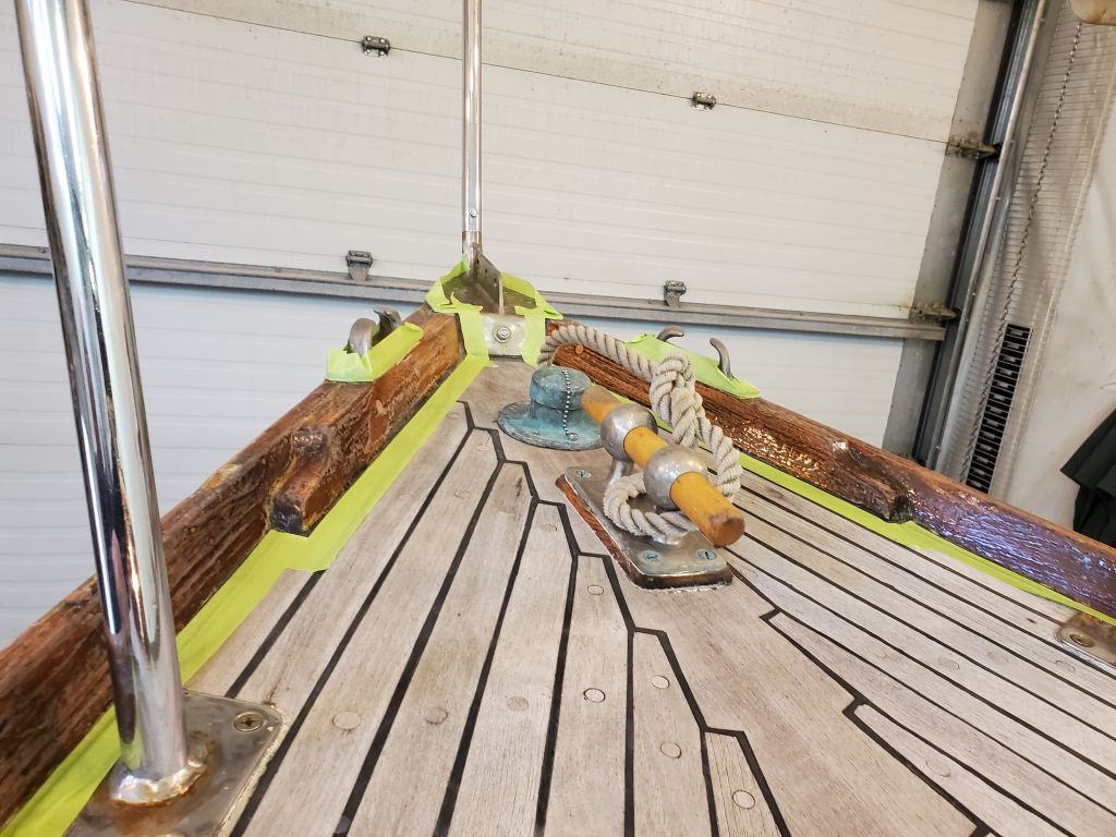
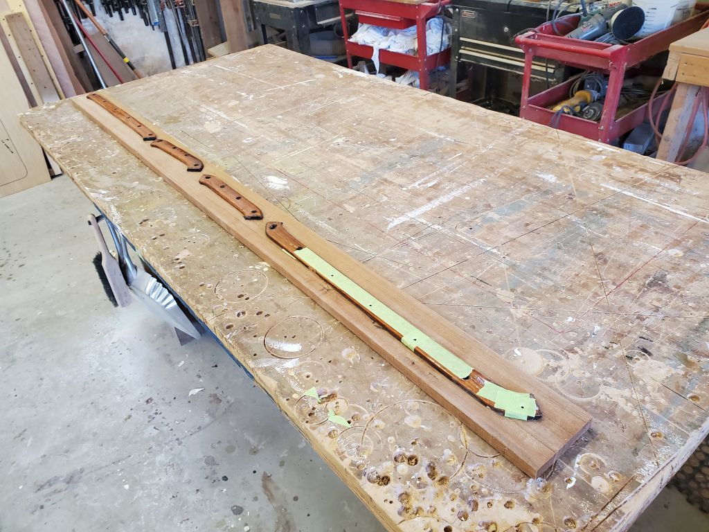
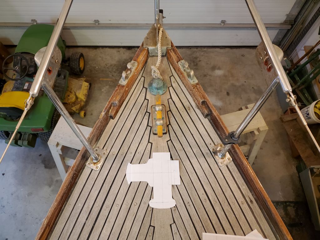
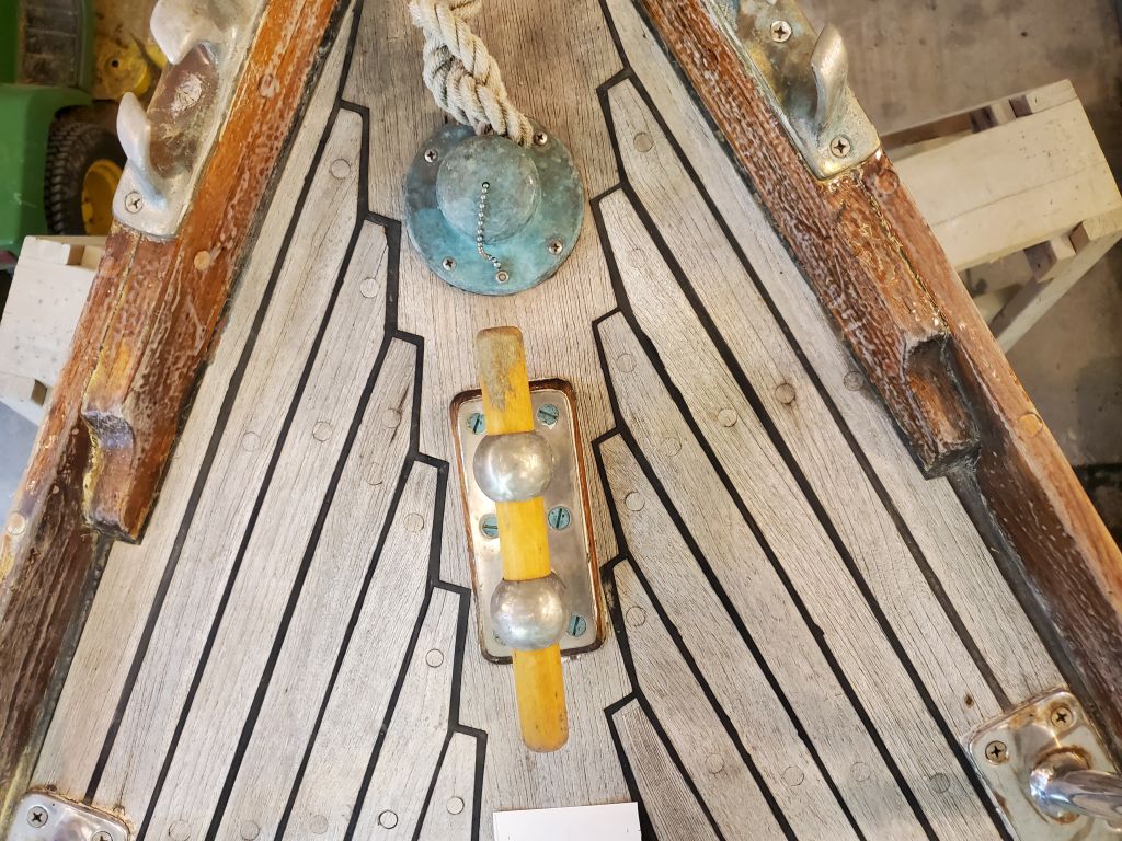
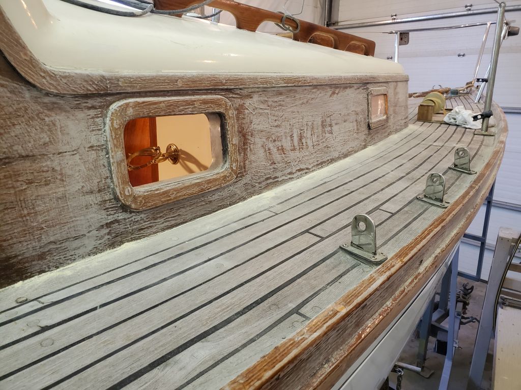
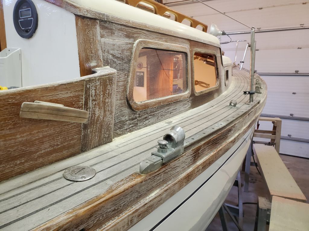
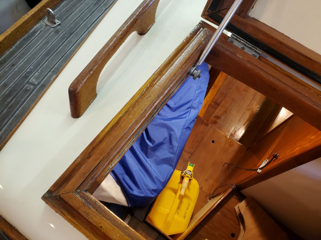
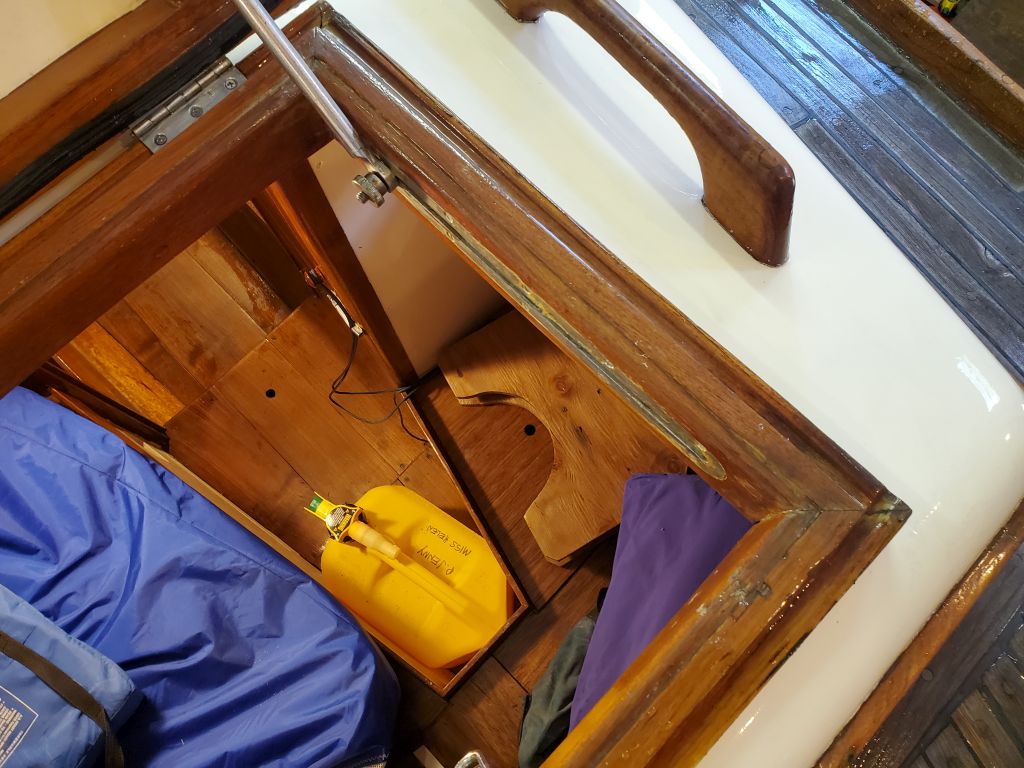
The owner was interested in exploring the possibility of a manual windlass, and I spent a little time making a rough, but accurate-enough, paper template of one likely candidate, the Lofrans Royal, to show the overall footprint.  Space on the foredeck was limited, and part of the exercise was to determine how well such an installation would fit.  Given the requirement for the chain lead straight out of the chain gypsy on the starboard side of the “windlass”–the center of that rectangular protrusion there–and the need for a roller at the stem in line with that, placement options were limited to centerline, somewhere aft of the mooring cleat roughly as shown.   Most rollers are about 3″ wide, depending on anchor type (some are narrower), and such a roller would fit between the center of the stem and the bow chock, but not with much clearance on either side, and such an installation would likely impact the utility of the bow chock on whichever side the roller was mounted.  At this stage, I’d not yet determined specifically what sort of roller would be needed here.

Inside the boat, the chain locker, as it were, extended aft to a spot approximately in line with the aft pulpit bases, so in the configuration shown here the windlass chain pipe would be aft of the chain locker.

In short:  a windlass installation would be possible, but with numerous complications and likely need to reconfigure certain things while making some tighter access to existing installations on the foredeck, and provide a means for the rode to enter the chainlocker cleanly, assuming a chain rode leading off the gypsy.  In addition, the gypsy on this particular windlass was chain only and wouldn’t work with rope rode, though the winch drum on the opposite side would.  But that seemed like it would be cumbersome to say the least.  Some windlasses have gypsies that work with combination chain/rope, though the chain needs to be spliced to the rope in a specific way for a clean transition.

Miss Helen 5

First thing, I lightly sanded the window trim, then applied another coat of varnish to all pieces.  These trim pieces would be ready for reinstallation after the weekend.

I installed a new gasket on the forward hatch, keeping it continuous at the corners with a small relief cut on the inside edge to allow the bend.  The new self-adhesive gasket material was 5/8″ x 3/8″, with a hollow center that allowed for ample compression.  I made the seam in the gasket at the center of the aft edge of the hatch.

Next, I cut and installed new gasket material in the opening ports.  The new rubber material was 5/16″ in both dimensions, with a slightly rounded top edge, and fit well in the gasket groove.  The gasket featured a hollow center to allow for compression, and seemed to offer good resistance and sealing when I closed the port, with gasket material visible from the outside when the port was dogged down.


Miss Helen 4

After an appointment away from the shop, I got back to work on the deadlight opening, removing the clamps and lightly sanding as needed to clean up any excess and cured epoxy.  The opening was now ready for reinstallation of trim and lens as soon as the remaining parts were ready.

To that end, I finished up prep work on the last two pieces of deadlight trim, which I’d had to lightly glue to fix some splits, then I applied the first of a couple coats of varnish to all the trim pieces.  The interior pieces just needed sprucing up before reinstallation, and I wanted a couple good coats on the exterior trim for protection before I installed the deadlight with sealant.

I removed the forward hatch so I could replace the gasket and work on the minor modification to the hasp setup.  Removal was a simple matter of removing the hinge screws from the hatch frame.  Once on the bench, I removed the old gasket and adhesive to prepare for the new gasket when it arrived.  Then, I removed the block securing the hasp latch so I could trim it slightly as needed to ensure a more positive seal around the hatch.

Now I turned to brightwork preparation.  I started with various small parts I’d accumulated on the bench, including the forward hatch, companionway boards, and the tiller.  I gave these all a sanding with 220 grit to prepare for maintenance coats of varnish.

I spent the remainder of the day working on the brightwork on deck, sanding the existing coating with 120 grit with a sanding block and by hand to prepare the surface for probably two or three maintenance coats of fresh varnish; I chose this grit because I thought the old coating needed a more aggressive approach to surface preparation given its condition and the overall situation.  The wood beneath the old coating had been heavily weathered and neglected when this owner bought the boat, and there remained plenty of grain texture in most of the wood, so the goal of this sanding session was not to correct that which could not be corrected, but only to prepare the relatively old varnish coating well for maintenance coats over the top.  Several areas where there were chips or flakes would require a couple early coats of touch-up varnish before getting to the full coats on all areas.  I did my best to sand out existing drips in the old coating, but resisted the urge to take such corrections too far as I didn’t want to sand through the old varnish.

By the end of the day, I’d made it around the boat sanding everything I could reach from the staging, including the toerails, outside coamings, and cabin trunk.  I left the cabin trunk immediately around the starboard forward deadlight alone for now, as I wanted the old coating to be intact when I reinstalled and bedded the window and trim soon, but once that was done I’d finish up the sanding there.

Miss Helen 3

Picking up where I left off, I worked to remove the glass lens from the deadlight frame.  The glass was a close fit all the way around, leaving little room to cut away the sealant and begin to pry the lens out, so it took some time to carefully work my way in through the sealant from both sides of the frame, cutting with a knife and using a putty knife to help pull out strips of sealant when possible.  Eventually, after several back-and-forth trips between inside and outside, I succeeded in freeing the glass without damage.

This left the inside trim (minus the vertical aft piece, which I’d removed earlier) in place and with plenty of sealant still holding it.  Most of the external sealant had stuck to the glass when I removed it, but there remained a film on the teak cabin side as well.

I’d already removed the screws securing the interior trim at the start of the project, so now it just took a bit more cutting and careful prying to remove the rest of the trim.

I cleaned up the opening and environs by scraping off the bulk of the old sealant, then sanding off the rest, leaving the rim of the opening clean and ready for new installation when the time came.

There was some looseness and a gap between the fiberglass cabinside and the interior and exterior teak veneers, and I thought it would help make the new installation watertight if I filled these voids to eliminate that potential passage of water and ensure a good seal otherwise.   So after finishing up the cleaning and then solvent washing the area, I masked around the opening on both sides to avoid undue messes, then forced some thickened epoxy adhesive into the gaps all around, and smoothed it over the rim of the area as needed.  I clamped the sections all around, and used some tape at the top edge to help resecure a thin strip of the exterior teak cabin side that had come loose during removal efforts.

Next, I scraped and cleaned away the sealant remnants from the glass deadlight lens, and the interior and exterior trim pieces, sanding the faying areas clean and lightly sanding the varnished exposed sides to prepare for new varnish before installation.  Two of the trim pieces had minor splits and are out of the photo being glued.

During a phone conference, the owner mentioned additional concerns over past leakage through the forward hatch and on the port side, and this prompted me to prepare for another water test to see if indeed I could find a way to get water to come through the forward hatch; I’d frankly been surprised that it seemed watertight before, though the video evidence of the first test was clear.

Because the two opening ports in the main cabin leaked through the seals when dogged down, with new gasket material now on hand I thought I’d install the new gaskets now, before I water tested the forward hatch, so that I could see if the ports were now leak-free.  I’d ordered new gasket based on what was visible around the ports, but when I removed the existing gasket, I was surprised to find another gasket beneath:  a more typical square gasket located in a groove in the port body.  The gasket that had been visible, and which I thought was the entire seal, was apparently a stopgap measure to enhance a non-performing square gasket.  I’d thought the visible gasket had seemed unconventional, having been expecting more of what I eventually uncovered.

The square gasket installed didn’t seem to offer any resistance to the port when closed, and was quite firm and non-compressible; it was a solid gasket, without a hole through the center to aid compressibility.  It was a typical 5/16″ square gasket, the type found in many port bodies.  So having determined its existence, I ordered some replacement prospects; the material I really wanted was out of stock with no information on availability, so I located a couple similar products that I hoped would be the ticket.

Now, I turned on my hose again and aggressively sprayed the forward hatch again, this time in a way to force a leak even if it didn’t want to.  I also focused the torrent all around the hatch where it met the deck, as the owner had raised this as a leak possibility too.  With a camera set up inside, and dry towels to catch and highlight the leakage, this time I found a solid leak on the forward half of the starboard edge of the hatch, right where it had originally seemed not to be sealing tightly during my first inspection.  Why it didn’t leak during my first test is a mystery, but it definitely leaked now; the other portions of the hatch, subjected to similar spray, did not leak.

Upon closer inspection now, with the hatch open, I found that the corners–particularly the starboard forward corner–of the gasket were mitered and not continuous where they turned the corners (or, if they had been, they were no longer).  So there was a good gap in the gasket at that corner, which certainly could account for the leakage.  That, along with the fact that the hold-down clamp wasn’t quite as tight as it could be, and didn’t adequately compress the gasket, certainly would allow leaks.

To solve this, I ordered new gasket material to replace the old, and also planned to slightly modify the clamping setup.  The fixed portion of the latch, located on the interior of the hatch frame, was mounted as low as it could go, but the corresponding part on the hatch top itself was mounted to a wooden riser block, and I thought if I could slightly trim down the block, I’d be able to increase clamping pressure when the latch was closed.  The block appeared to be mounted with screws, so hopefully it would be easy to remove and modify.

This time, I also water-tested the port deadlights, which I’d not done previously since I’d not been aware that leaks had been happening on the port side; my notes referred only to the starboard side, opening ports, and forward hatch.  But the owner had let me know that there had been some water on the port berth as well, and while it may have come from the non-sealing opening port, now I wanted to test the deadlights too and hope that they proved watertight.  I did not find evidence of leakage from the deadlights, though water did come in through the now-ungasketed opening port.

Miss Helen 2

Now that I’d determined the apparent source of the deck leak–the forward deadlight on the starboard side–I moved on with the repair, starting with the exterior deadlight trim.  I’d first started taking trim off from the inside, hoping to avoid disturbing the well varnished-in trim on the outside, but the nature of the deadlight’s assembly was such that removal of the trim and glass from outside was required.

The good news was that the owner had removed and reinstalled all these pieces and parts during his restoration, but even that was now many years past and, as with most things, not knowing exactly what I’d find as I dug into it was the hardest part.

The teak trim over the glass deadlight was bunged in place, presumably with screws beneath the bungs.  So I started by carefully drilling out one of the bungs, eventually revealing the screw beneath.  It took a while to determine what sort of screw it was–a slotted bronze head–so I could finally clean out the slot and remove the screw.  I was surprised to find that the fastener was a 3/4″ machine screw, not a wood screw–apparently because the actual structure of the cabin trunk was fiberglass, not wood, beneath the exterior and interior veneer paneling.  It was not easy to remove the screw, but an impact gun set on its lowest level helped break it free and spin it out.

The first screw had taken roughly an hour to remove, all told, and with 16 screws remaining around the deadlight, I feared I might never get to the last one.  Fortunately, now that I had a better sense of what was what, the remaining three screws on the forward trim piece came out more quickly, and soon I pried off the trim.  This revealed the edge of the glass lens near the forward edge of the opening; however, the lens sat well below the surface of the surrounding wood, meaning that a lot of sealant had been required between the trim–which ostensibly pinned and sealed the lens in place–and the lens itself.

Next, I removed the top section of trim, with no particular issues in removal.  Here, I found the glass lens was nearly 1/2″ below the opening in the cabin side, a very large gap, and the sealant had many voids and pockets that may have contributed to the leakage seen, even though the seal here was good enough that none of the water from the leak test entered the boat from the window itself–all the leakage was channeled somehow down around the window to where it finally came out above the berth.  Given the state of the sealant here, it made more sense.

In this manner I continued with the remaining two trim pieces which, along with some unrelated delays from other business, ate up the rest of the afternoon and, as the process drew out with various difficulties, I wasn’t sure if I’d meet my goal of removing all the trim today.  Two of the screws at the bottom aft corner fought removal by normal means, forcing me to drill out their heads so I could remove the trim, and then the long bottom piece of trim turned out to be extremely well-adhered, making its removal a tedious and nail-biting battle between careful prying progress and risking damage to the trim.  Eventually I prevailed, but by then it was so late in the day, and the process had been so frustrating and tiring, that I elected to leave the glass lens in place for now, not daring to try and remove it till I was fresh again.


Miss Helen 1

I first came to know the boat that became Miss Helen, and her owner, more than 20 years ago.  At the time, I was doing some marine surveys, and was hired to look at this 1967 Frisco Flyer, which had been abandoned in a small boatyard out on Vinalhaven Island, ME.  I traveled out to the island with the eventual owner to inspect the boat; the boat was generally sound, but had been neglected for many years, and required a major overhaul.  The owner’s family had a property on the island, which is how he came to find the boat.

The owner took the boat, now on a new trailer, back to Wyoming, where he lived, and spent 10 or more years restoring her before enjoying sailing her in Montana for several seasons.  But recently be brought the boat back to Vinalhaven to sail in the summers, and this year left her with me to look into a nagging deck leak problem, among some other small maintenance chores.

I began the project as usual by repositioning the boat on her trailer more in the center of the shop (I’d had her pressed to one side for storage during most of the winter) and setting up staging to ease deck access.

The owner reported that the deck leaked directly over the starboard berth–his wife’s berth, as it happened–but he was not sure from whence it came.  So my plan was to flood this area with water to recreate the leak, and then take it from there to figure out the cause.  The deadlights were an obvious candidate, but the owner wasn’t sure if some of his deck work might have left an opening for leakage as well, and had mentioned his worries about the seam where the decking met the cabin trunk, as well as some other possibilities.

In the cabin, I started by removing a piece of trim at the lower edge of the cabin trunk, removal of which would expose the bottom edge of the wooden veneer and the deck edge.  The trim, which had been removed during the owner’s project, was secured now with round-head bronze screws, making removal straightforward.

Next, I set up a hose and flooded the area with a heavy shower spray for some time, which definitely succeeded in creating the leak below.  The leak dripped from a consistent point just below the forward edge of the forward deadlight.

The owner also mentioned concerns about the forward hatch, so I also spent some time flooding this area, but could not create a leak around the hatch.  That’s a good outcome.

There were two opening ports in the main cabin, and the owner mentioned leakage there as well; indeed, both leaked when flooded, but it turned out the port side had been not dogged down tightly.  However, the design of these ports held water in the spigot, against the seal, and the seal installed appeared to have been indelibly compressed by the port frame, causing a minor drip even when the ports were dogged down tightly, as the spigot was angled inwards and could not drain fully.  It’s asking a lot of any port seal to stand up to a constant pool of water even under perfect circumstances, but after inspecting the seal I thought I’d try replacing it with something new and see how it performed.

Having now created the leaks, it was time to get more scientific about figuring out where the leak came from.  First, I wanted to eliminate the deck itself as a candidate, if possible, so I set up my hose to flood only the deck itself, not the deadlights, to see if the leak continued.  Happily, there was no interior leak with this setup, which meant the unsavory task of trying to repair the decks or cabin trunk seam would not be necessary.

Since the position of the leak inside was consistent, and there didn’t seem to be multiple leaks, it seemed that the forward deadlight was the culprit.  Not sure how these were assembled or sealed, and with the exterior trim bunged and heavily varnished into place, I chose to start carefully with the interior trim to see if its removal would allow the deadlight to be disassembled.  But after removing the after L-shaped vertical piece of trim with some difficulty, it was immediately clear that the lens of the deadlight was actually secured against the interior trim, as I could see the exposed edge of the glass lens inside the newly-exposed opening (the point of the putty knife is directly on the edge of the glass).  So it looked like I’d have to remove the exterior trim in order to free the lens and work towards rebedding the entire deadlight–including the interior trim/frame, but the remaining three pieces would have to await removal of the outer trim and lens.

Newer posts