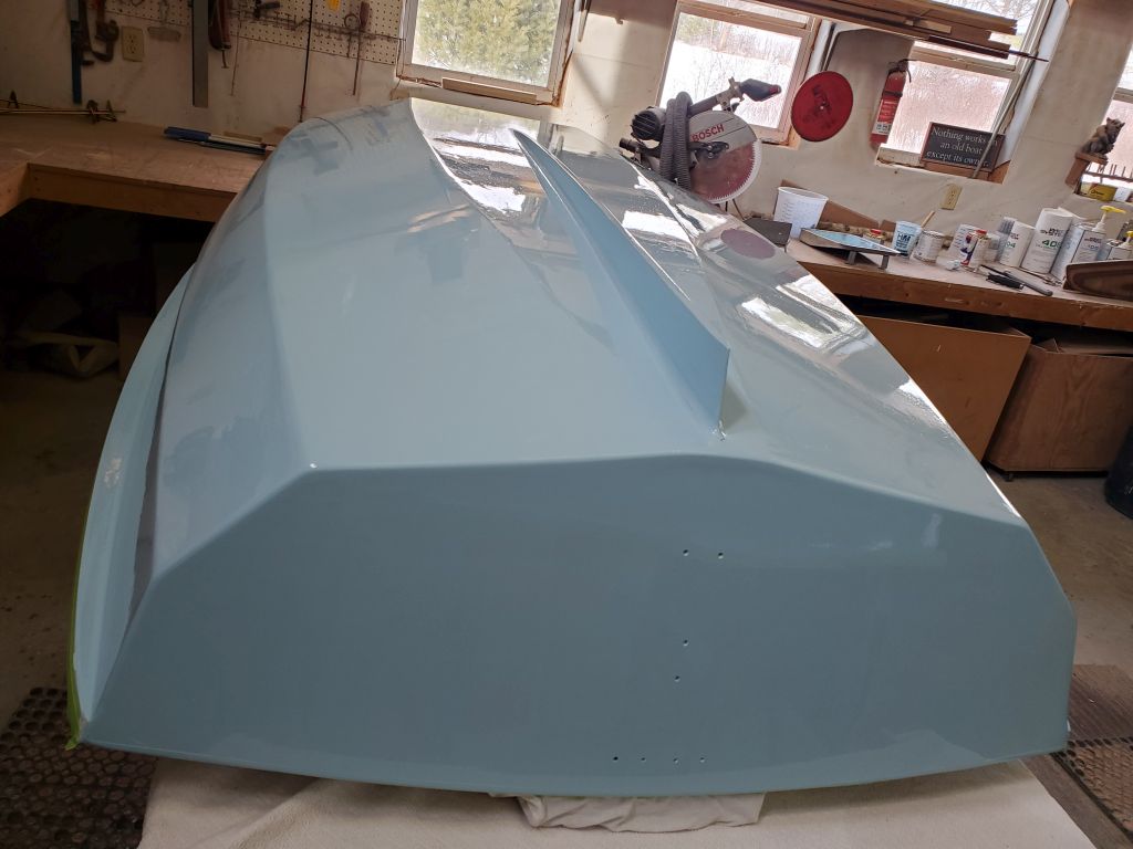
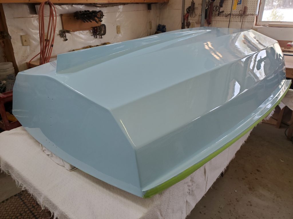
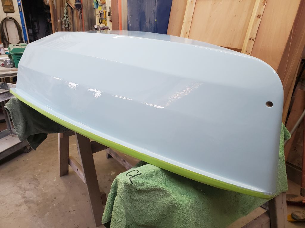
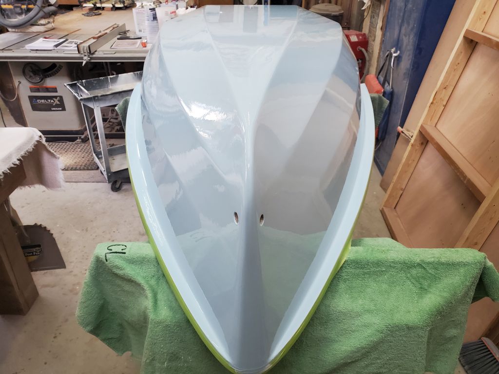
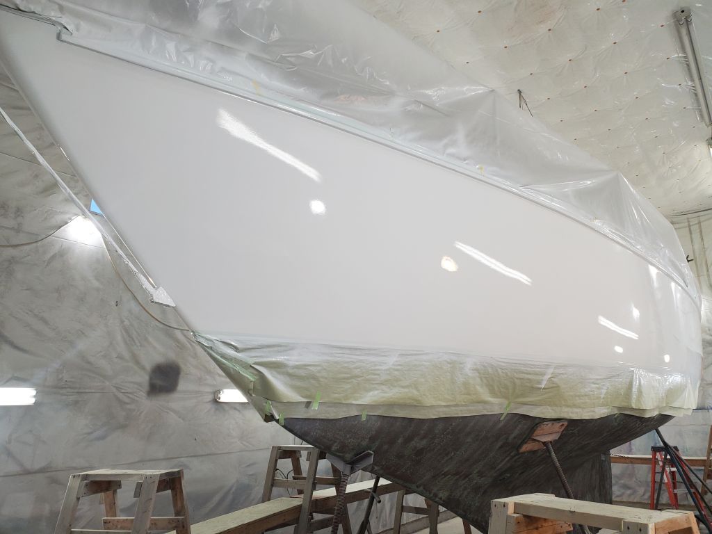
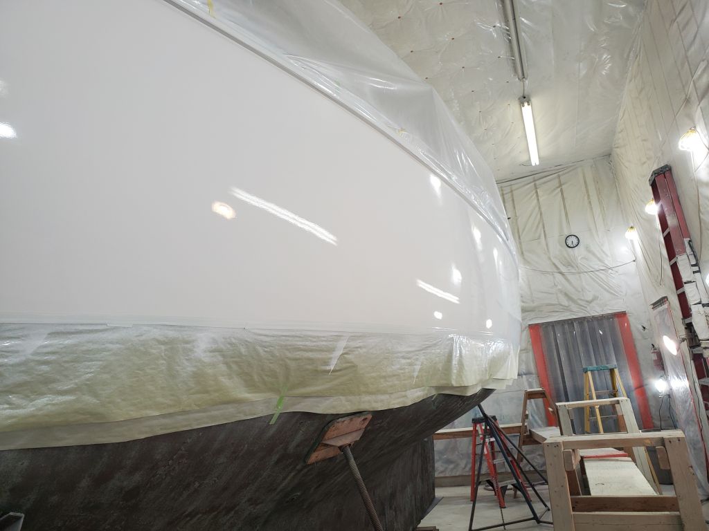
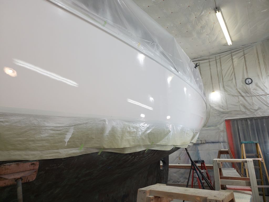
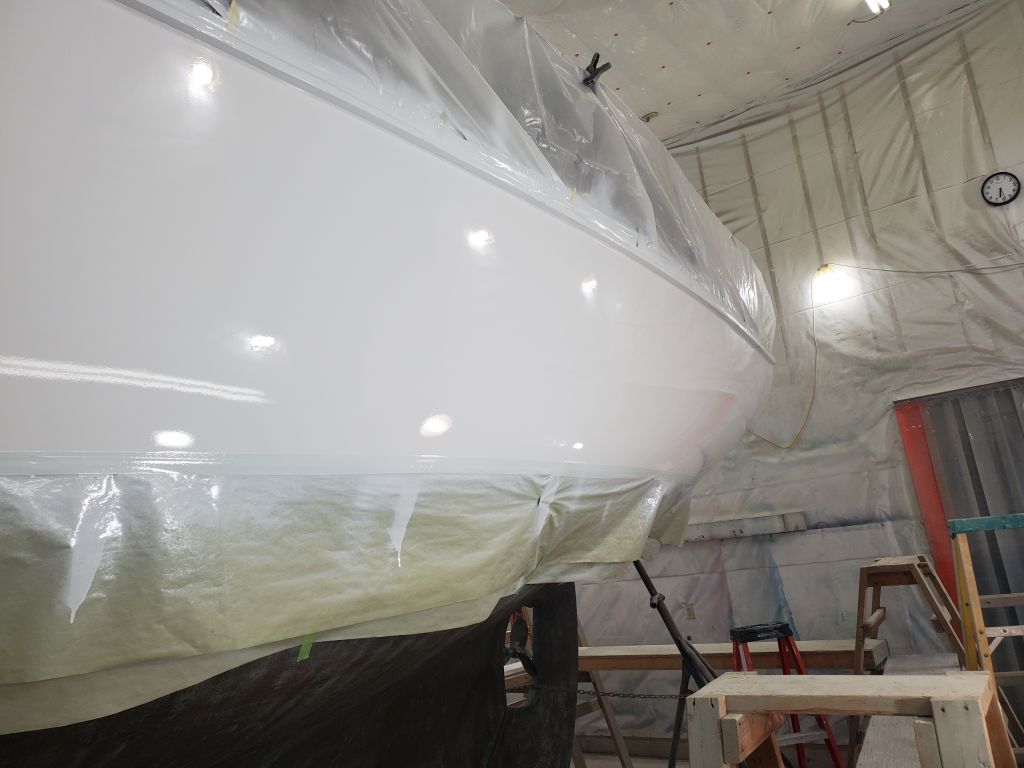
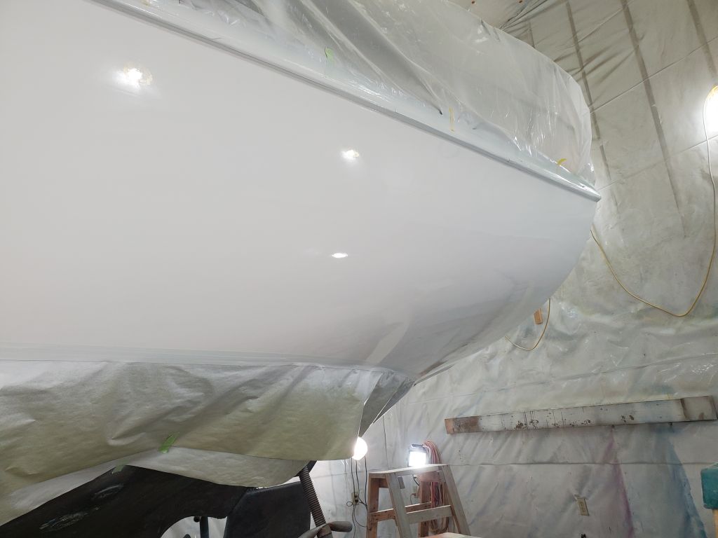
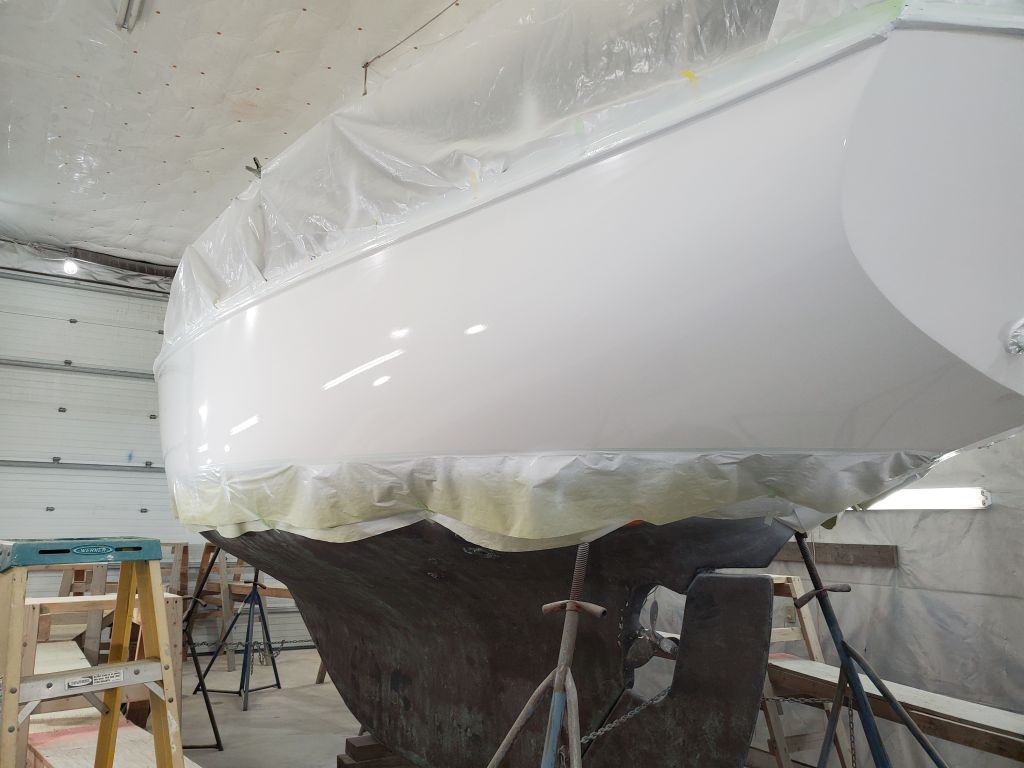
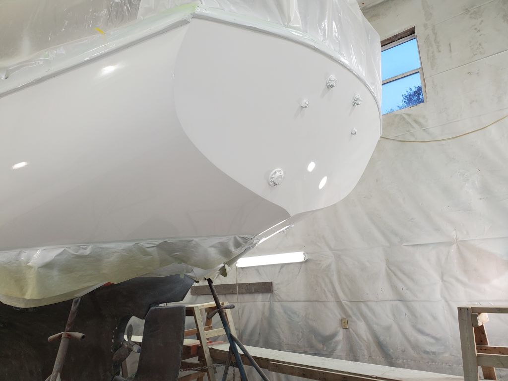
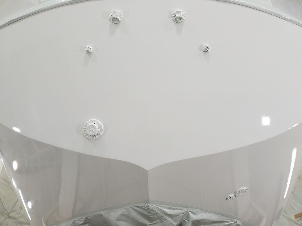
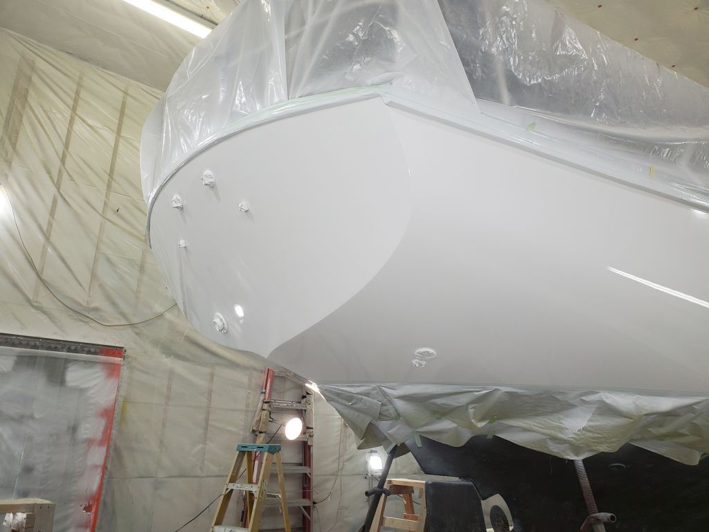
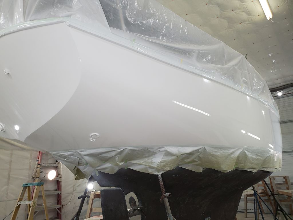
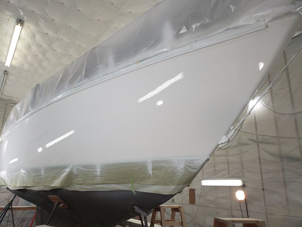
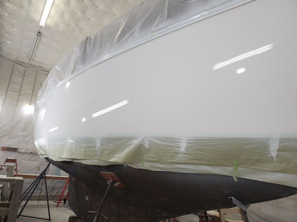
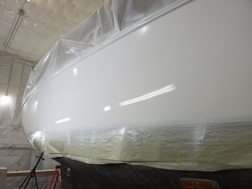
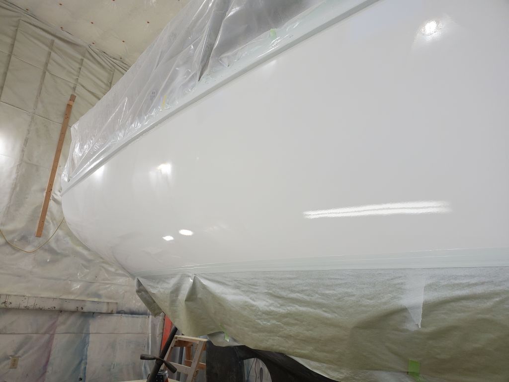
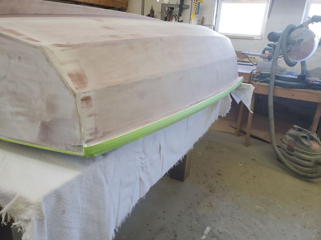
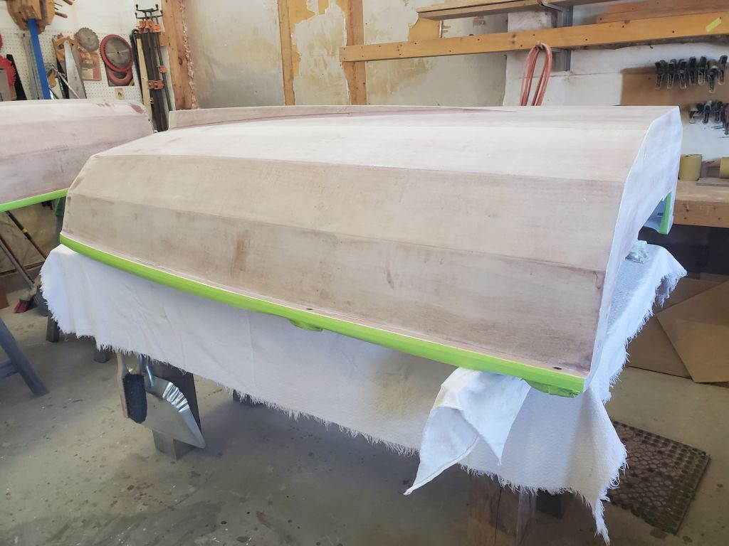
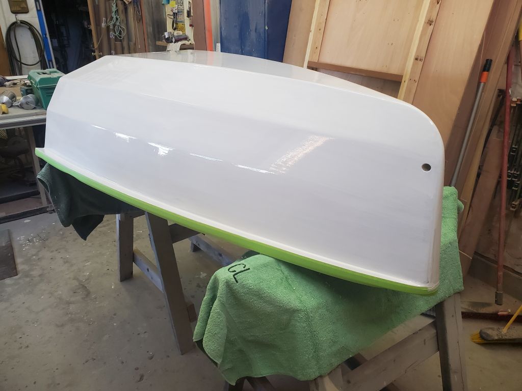
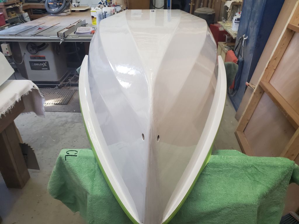
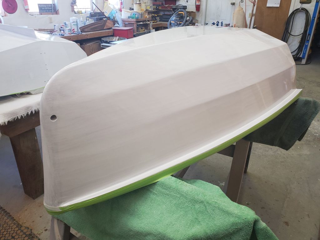
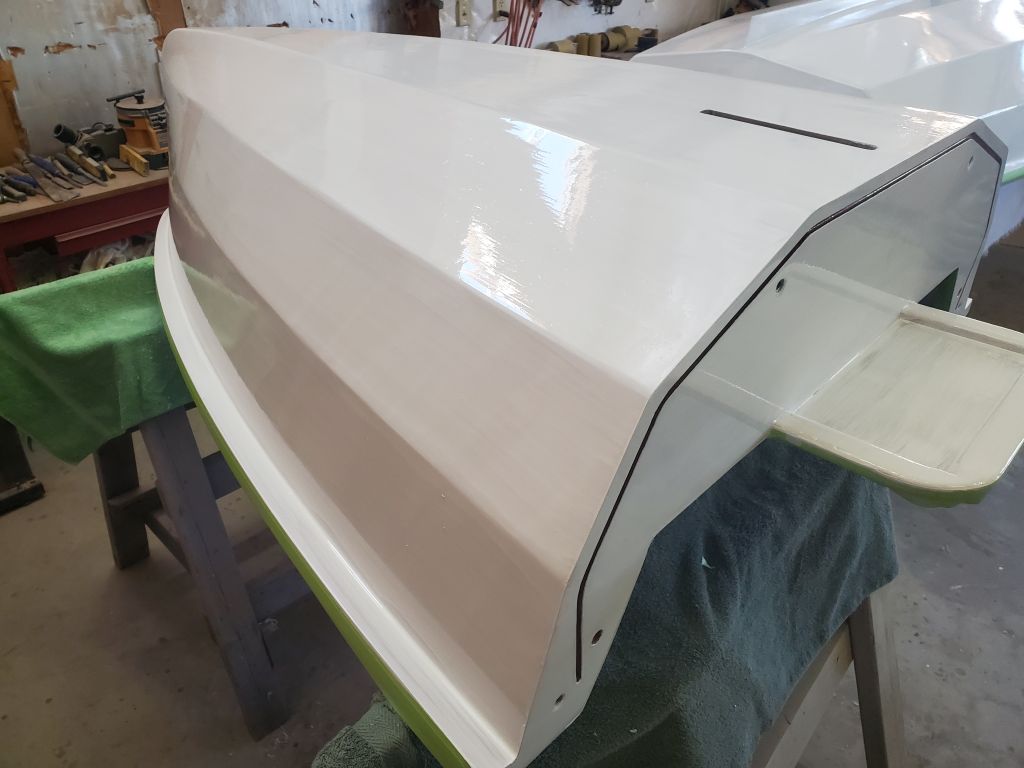
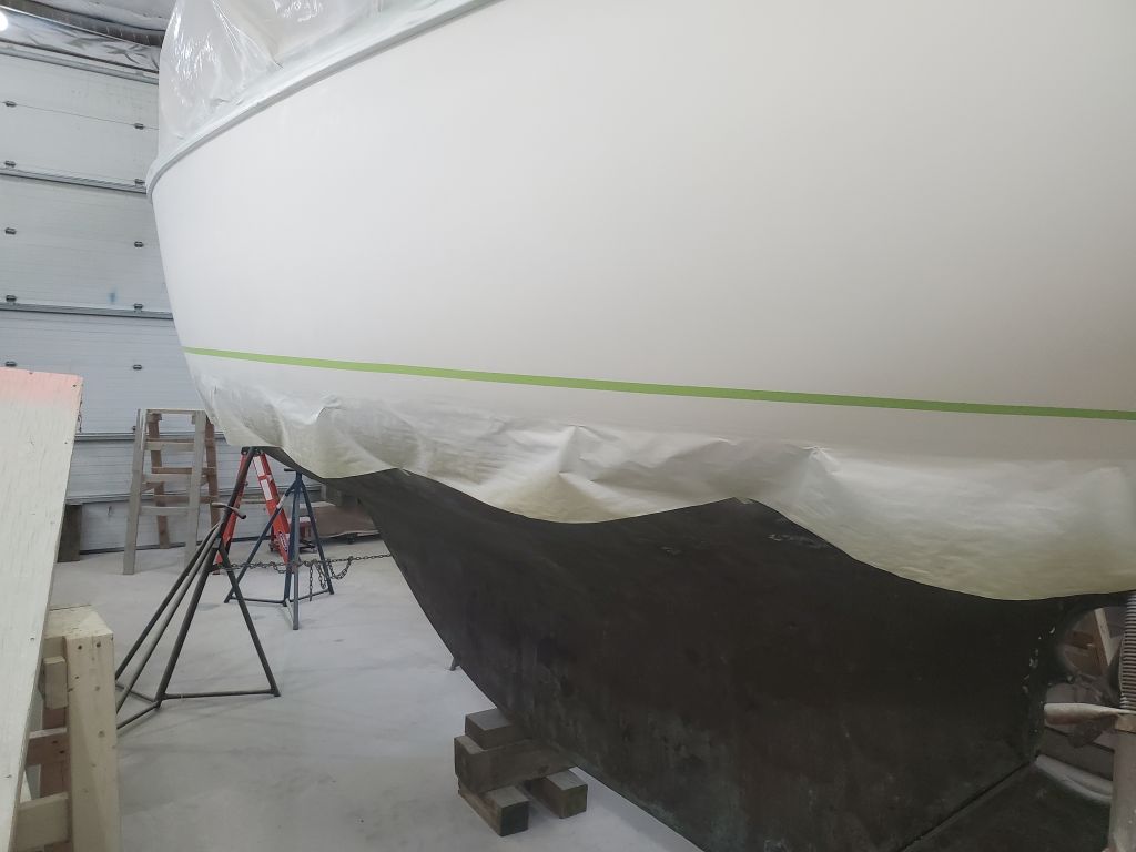
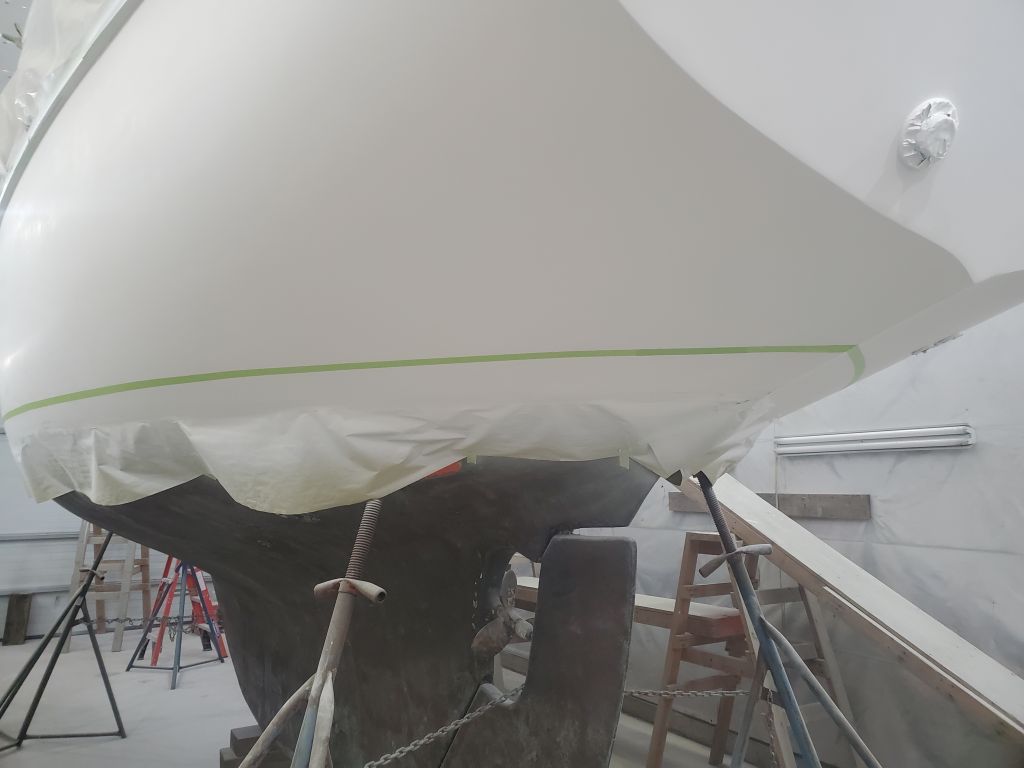
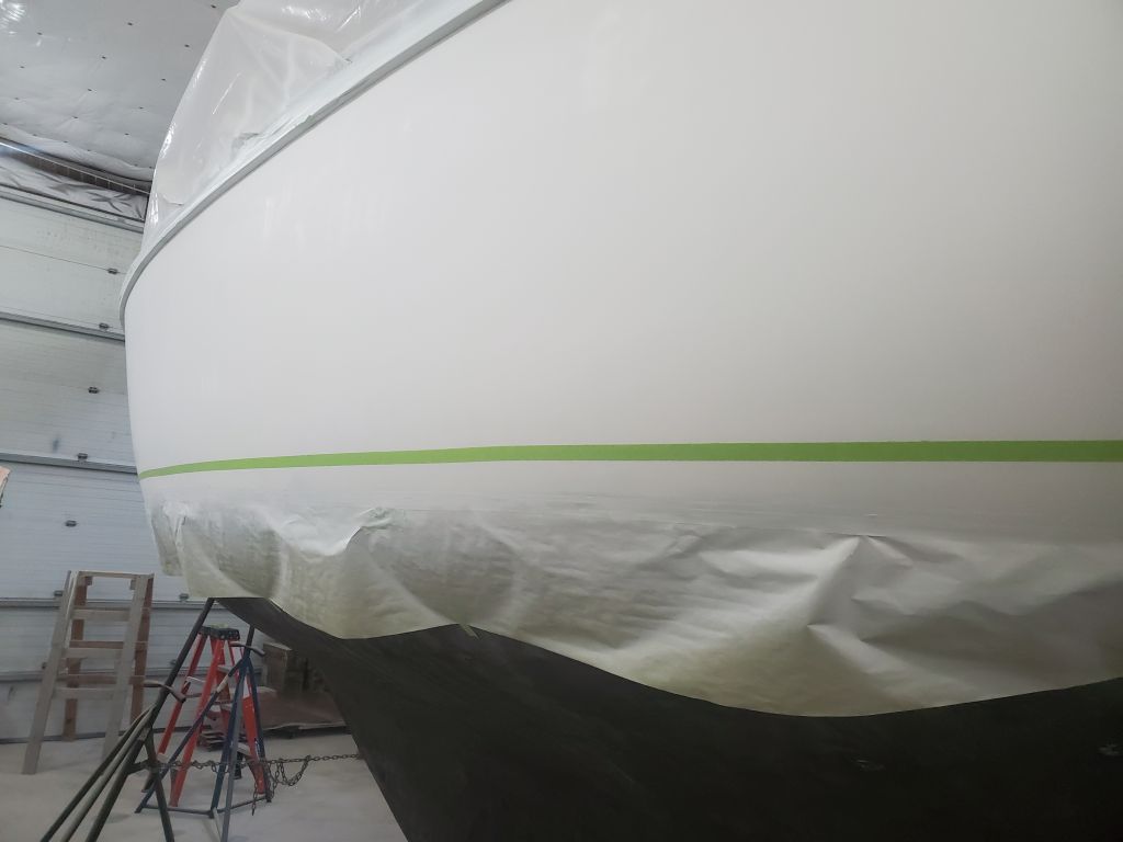
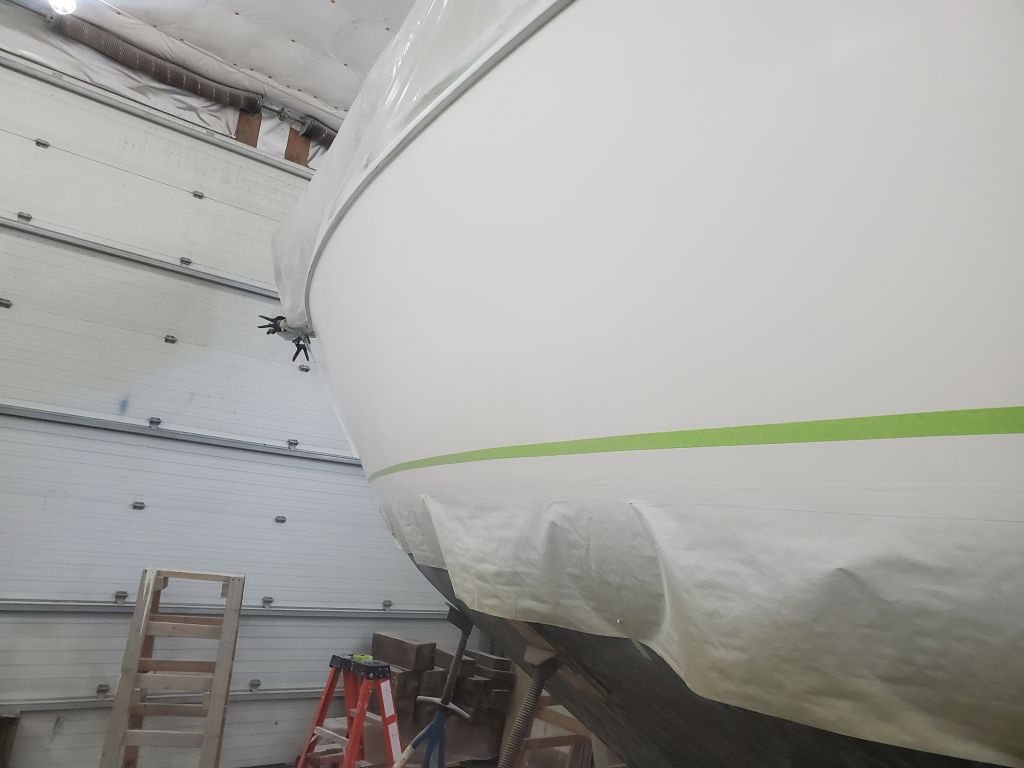
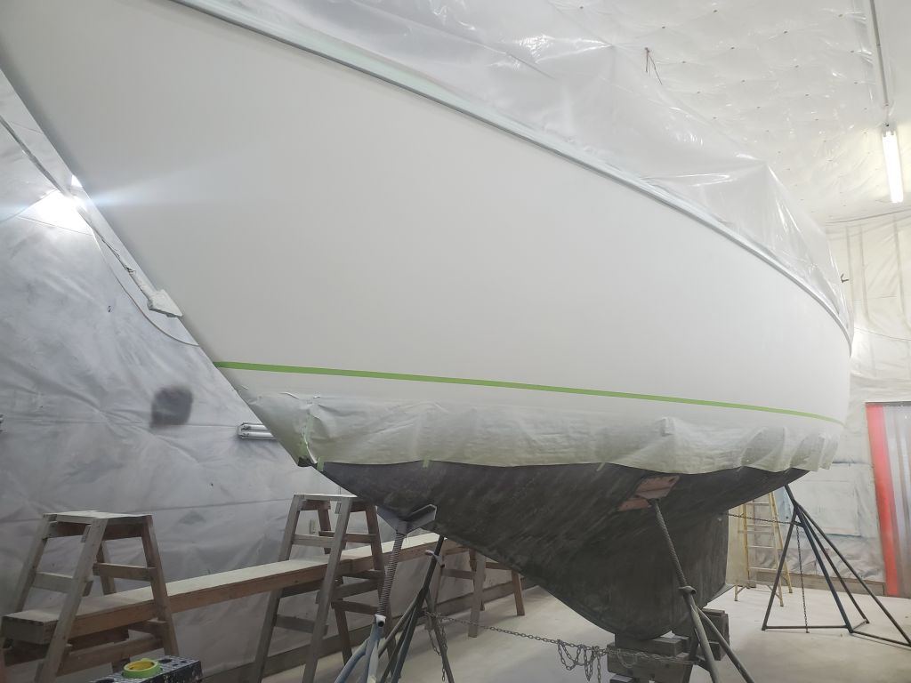
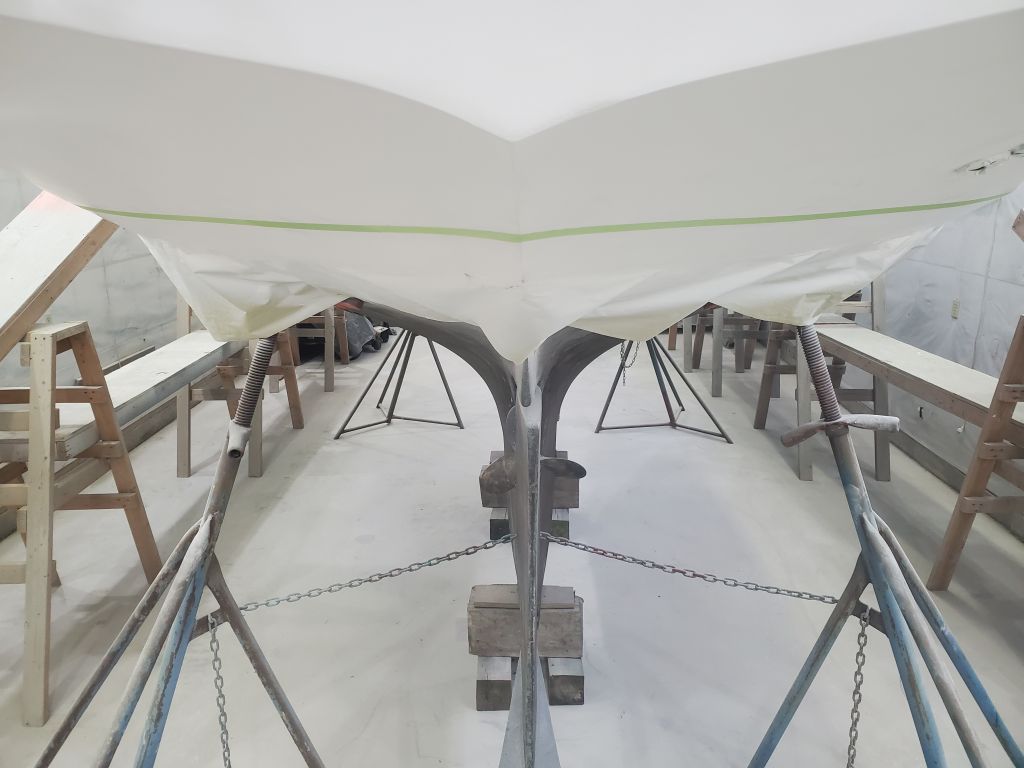
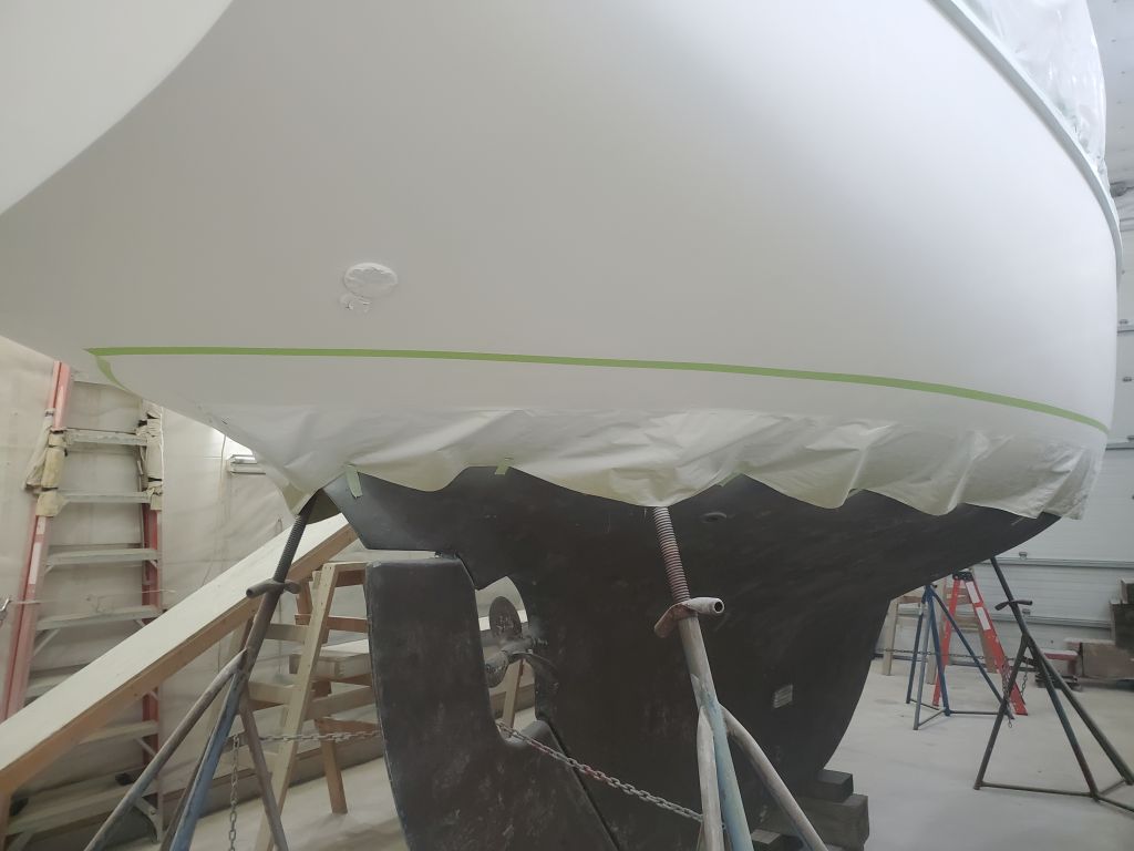
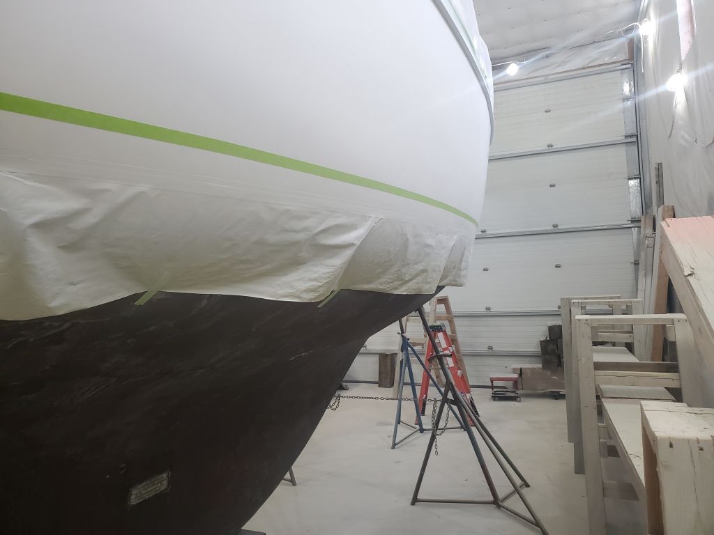
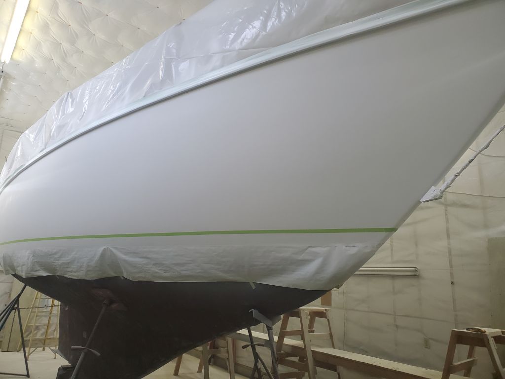
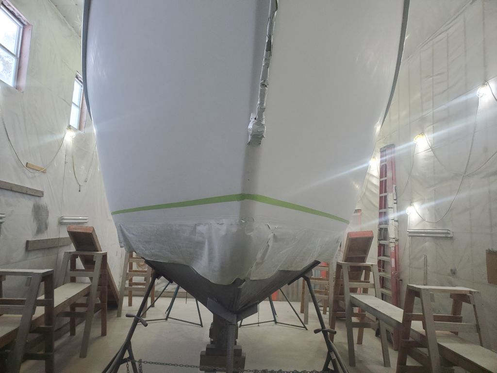
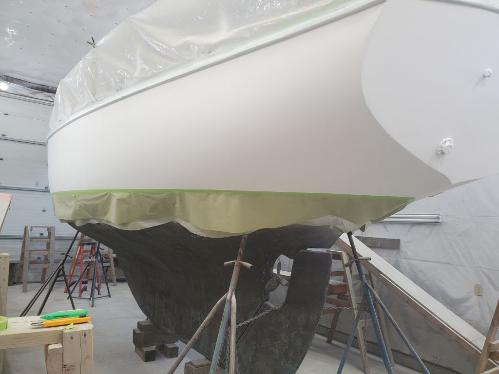
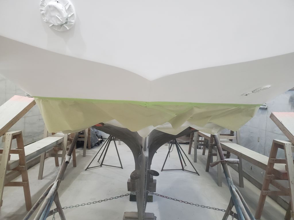
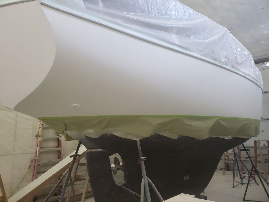
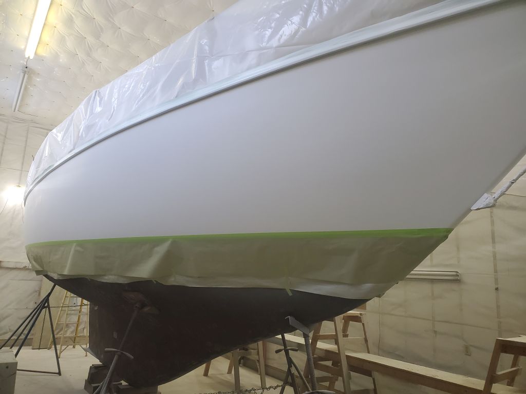
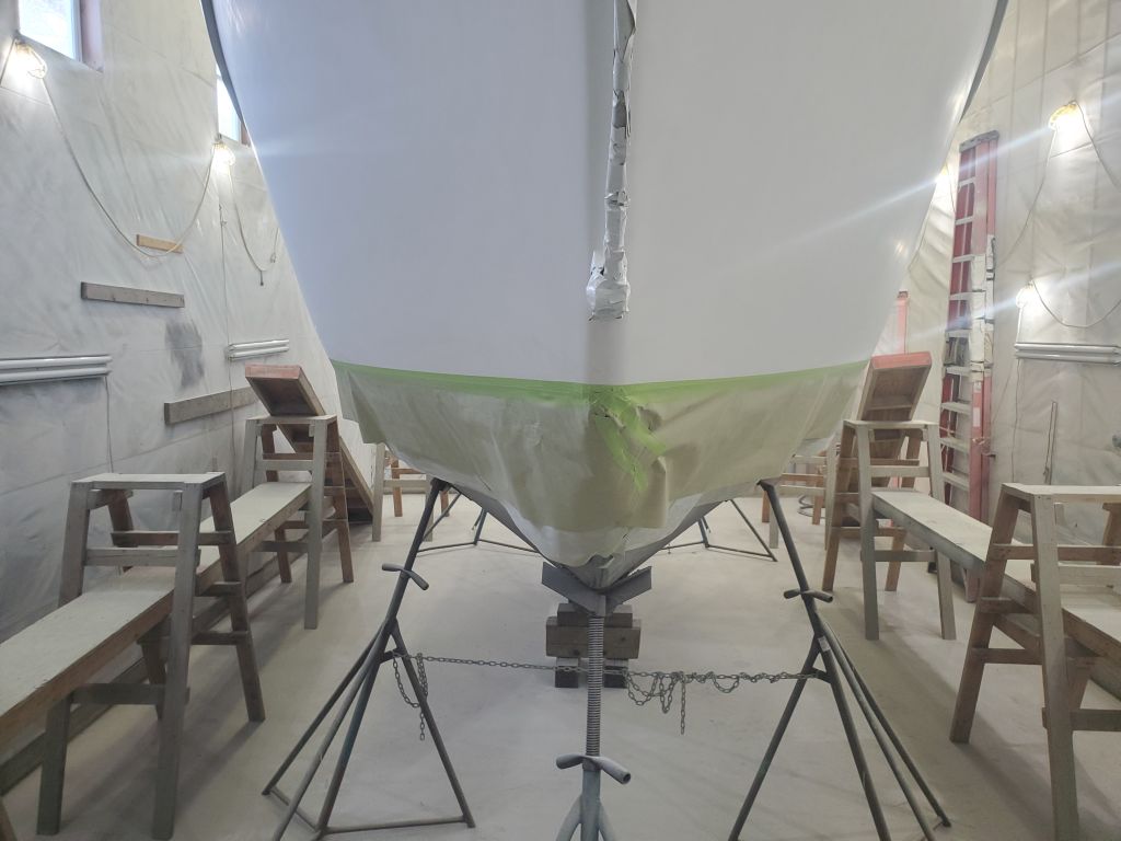
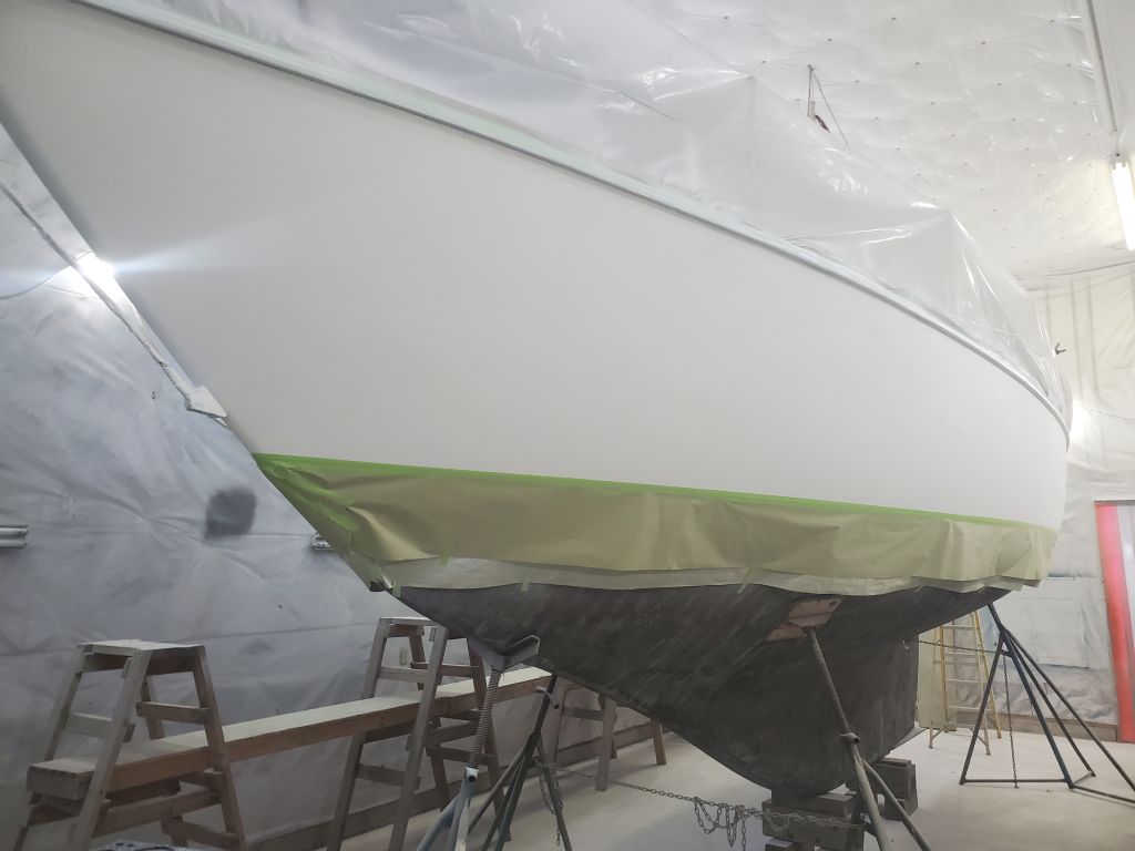
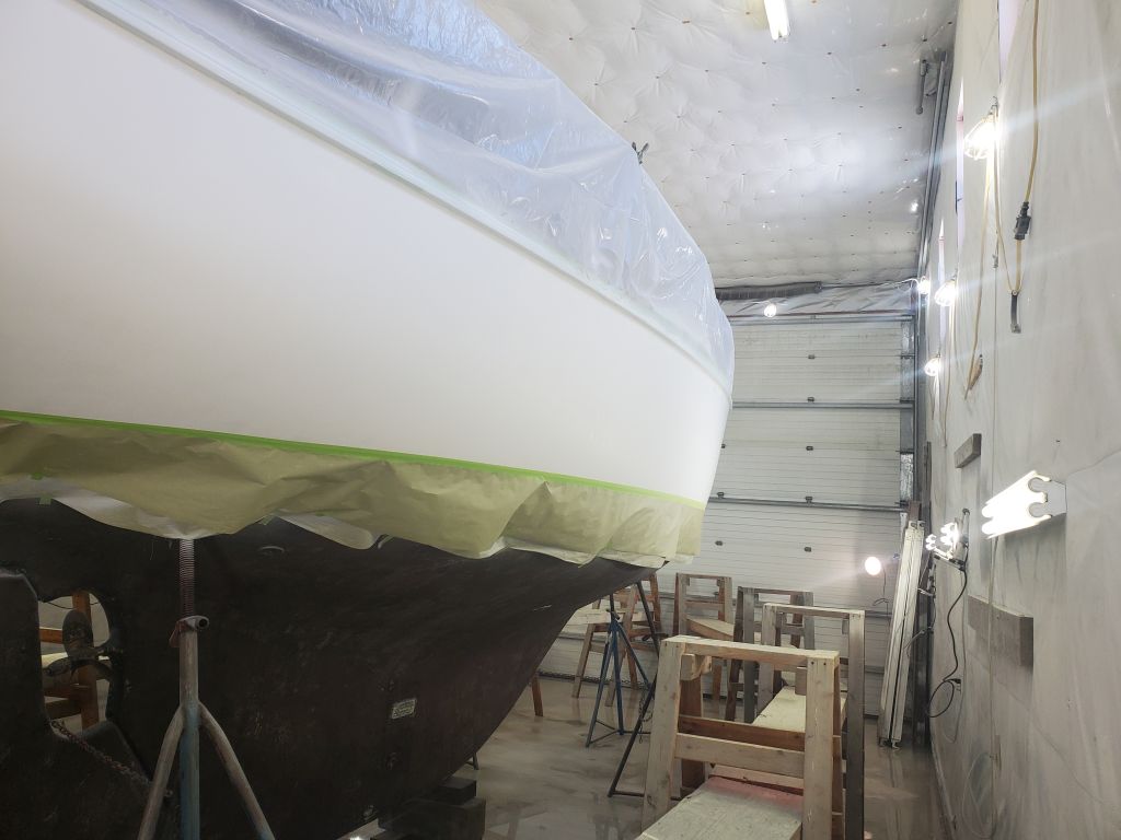
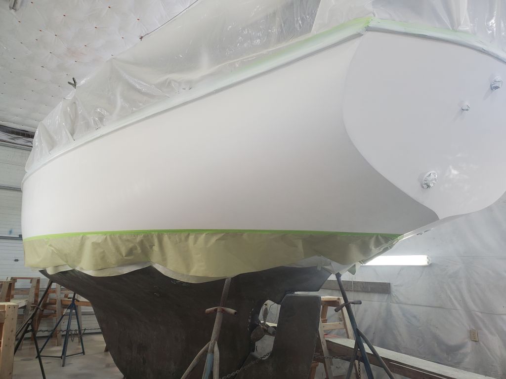
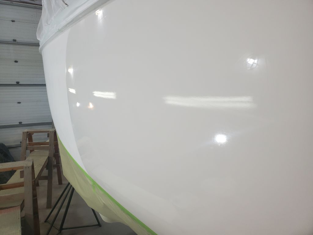
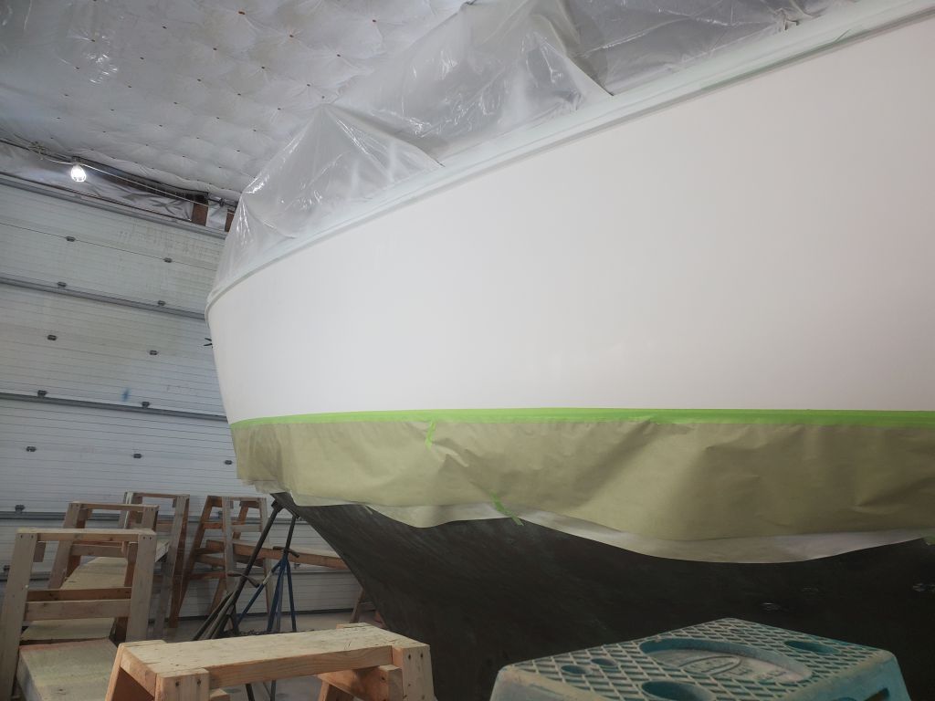
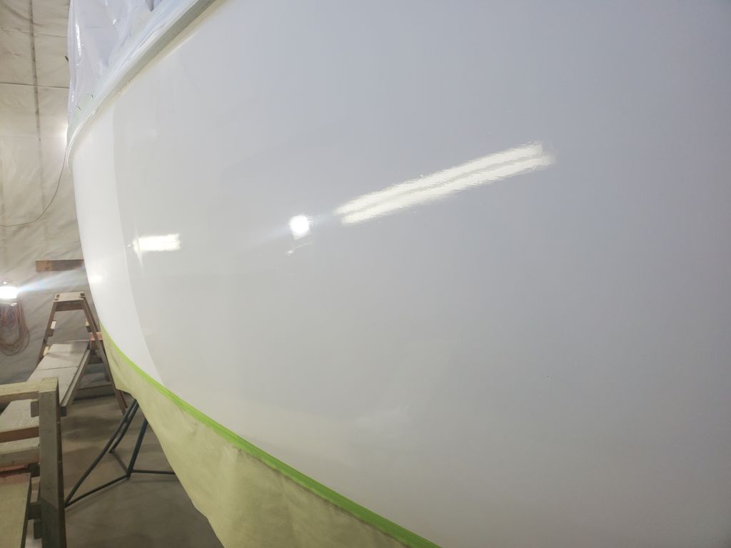
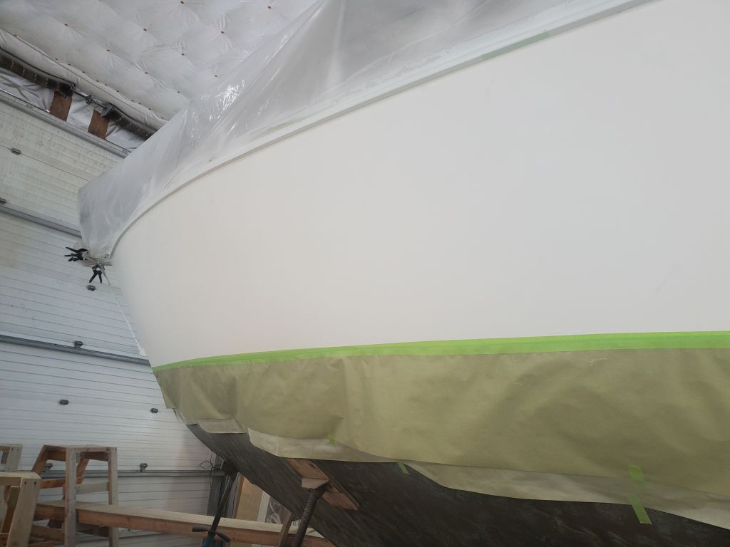
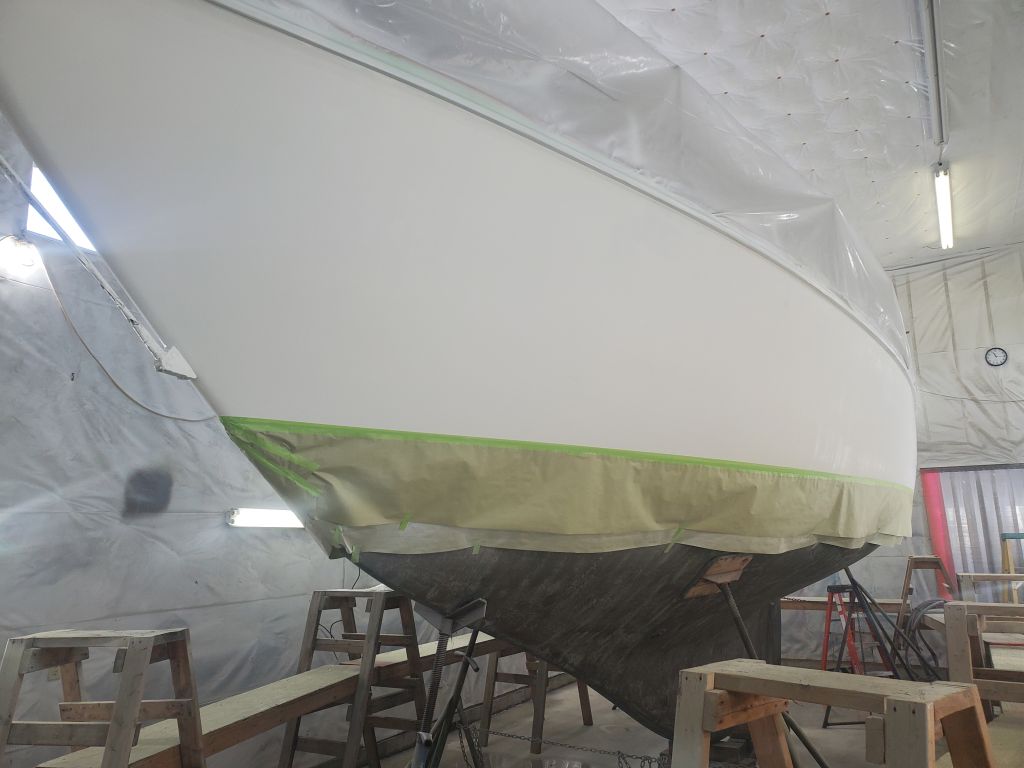
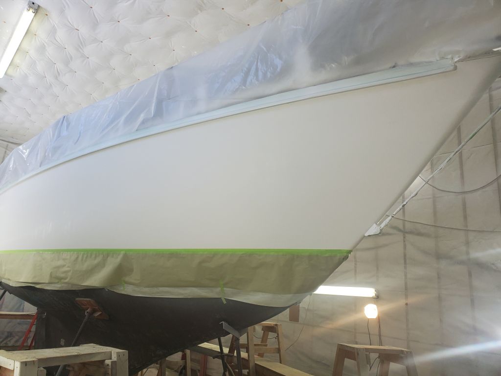
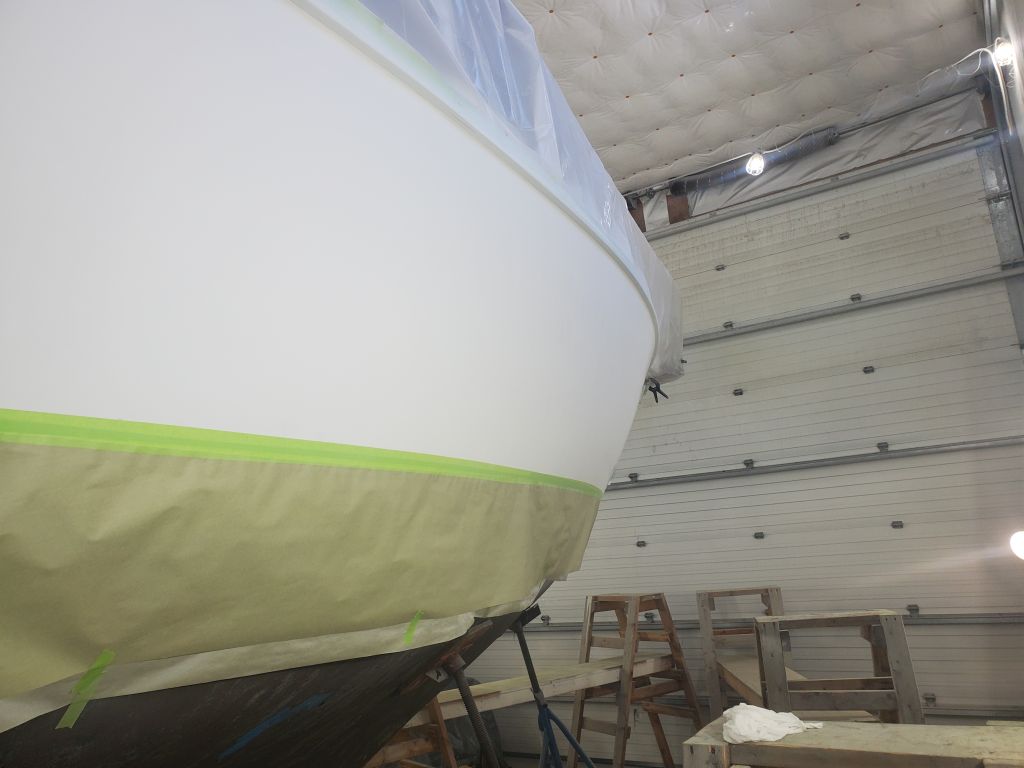
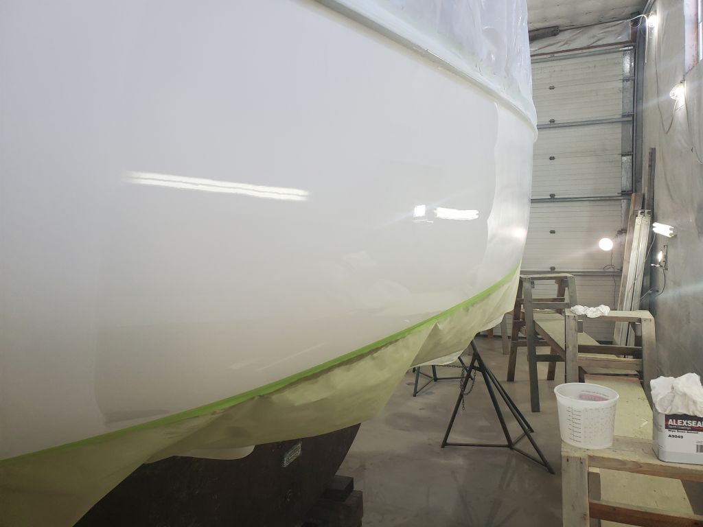
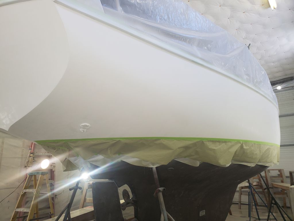
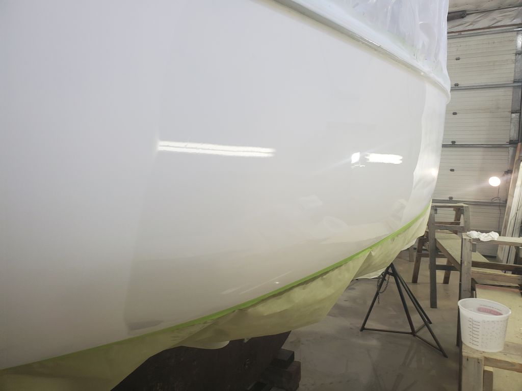
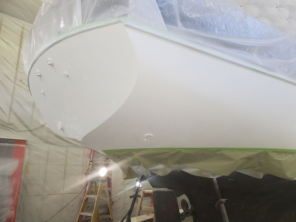
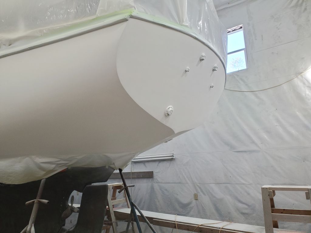
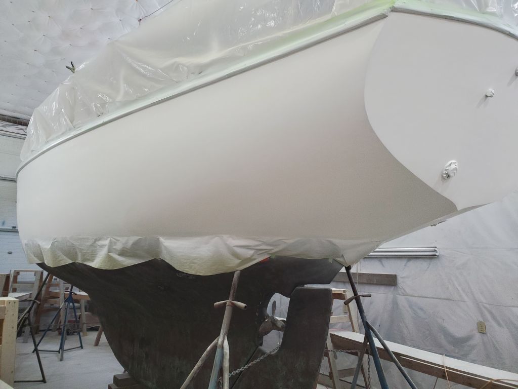
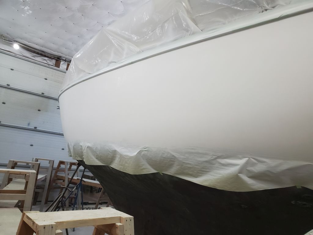
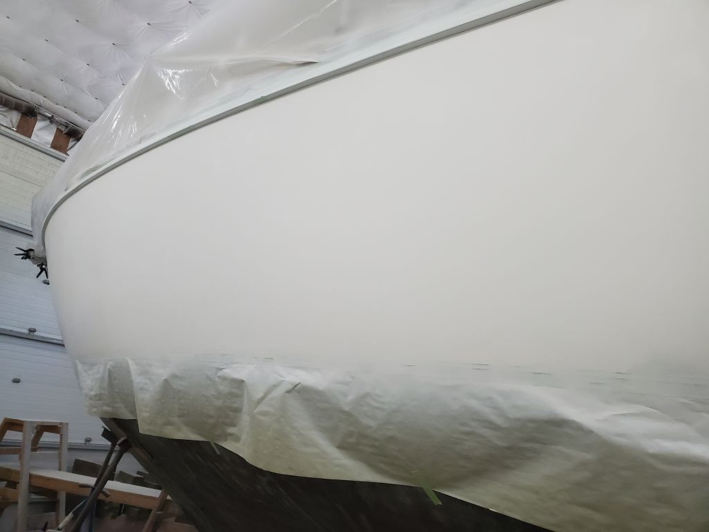
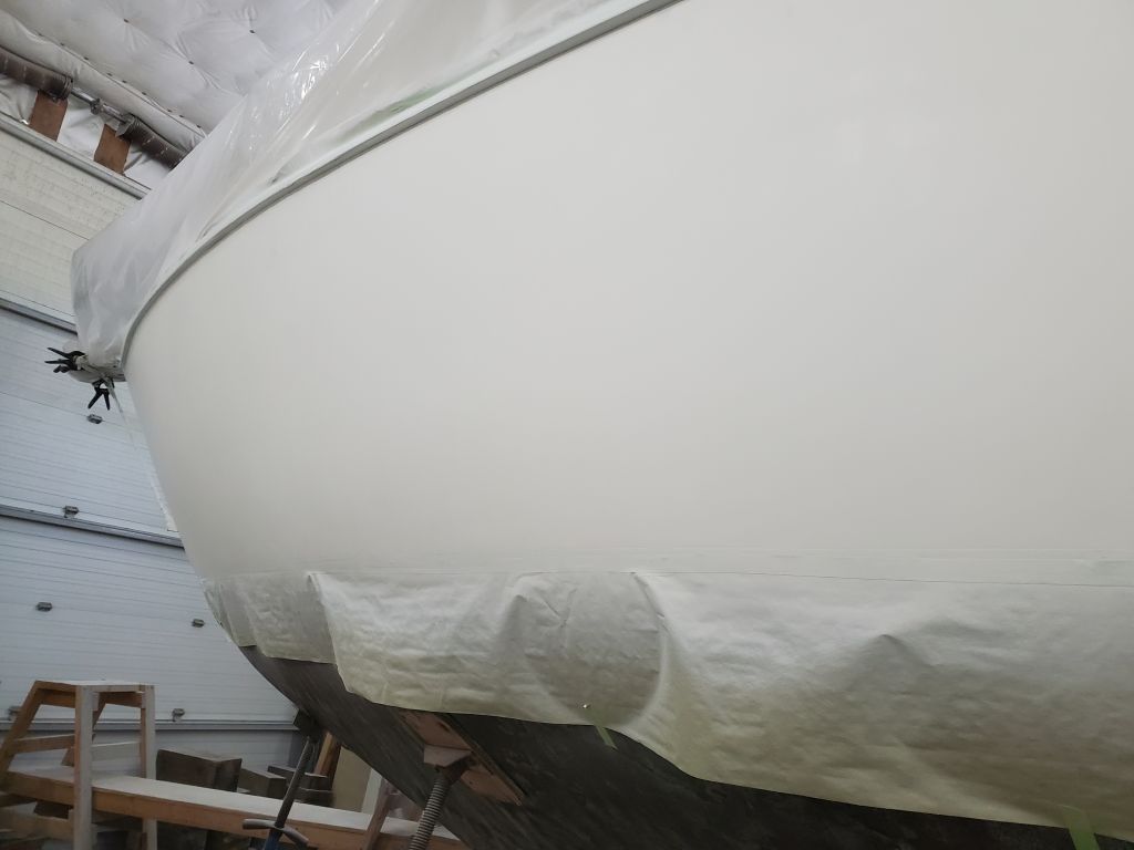
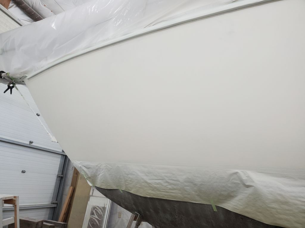
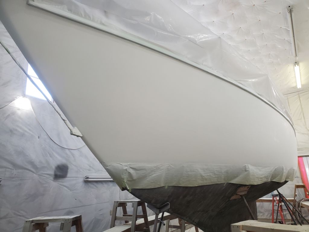
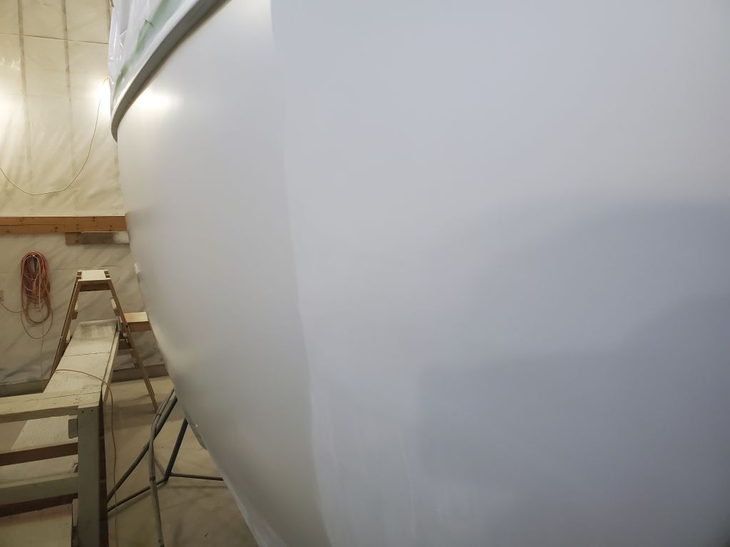
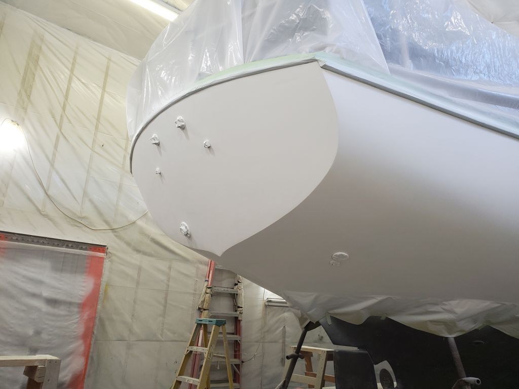
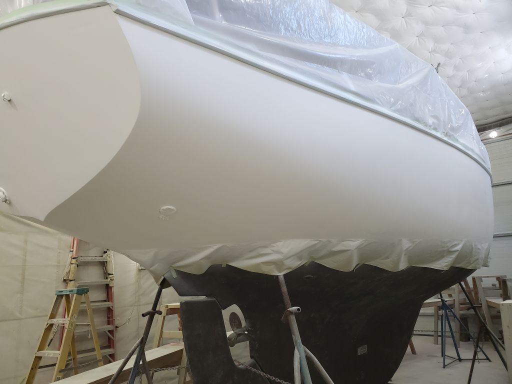
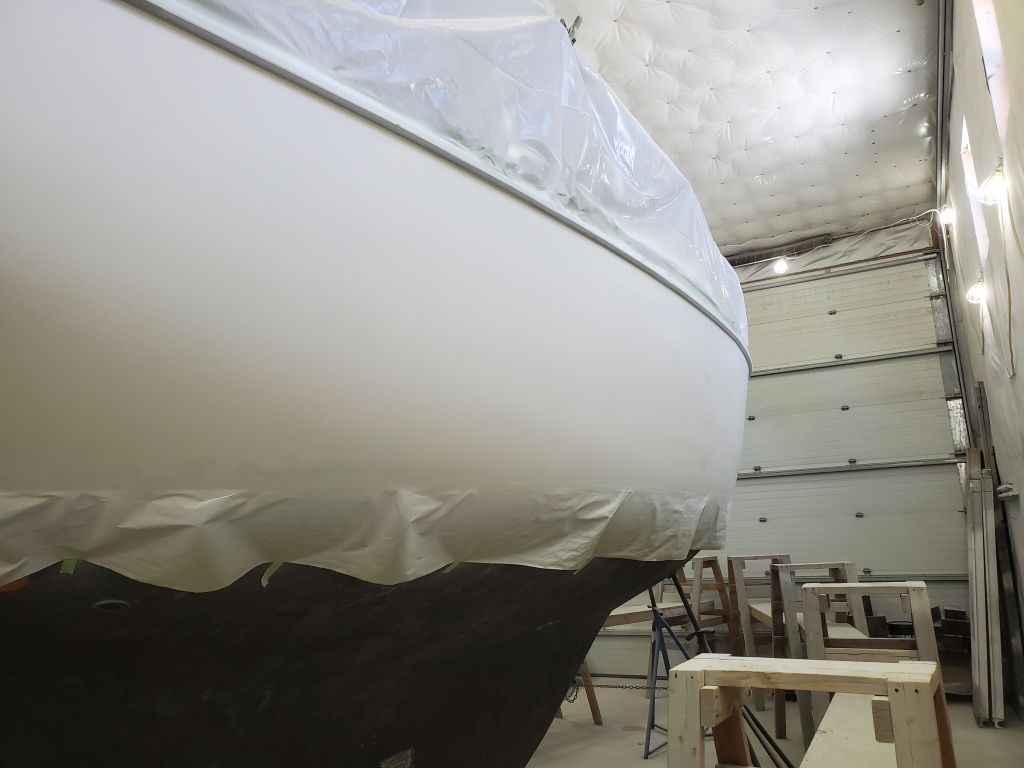
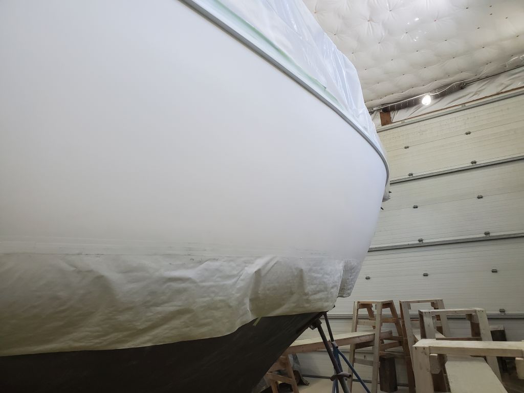
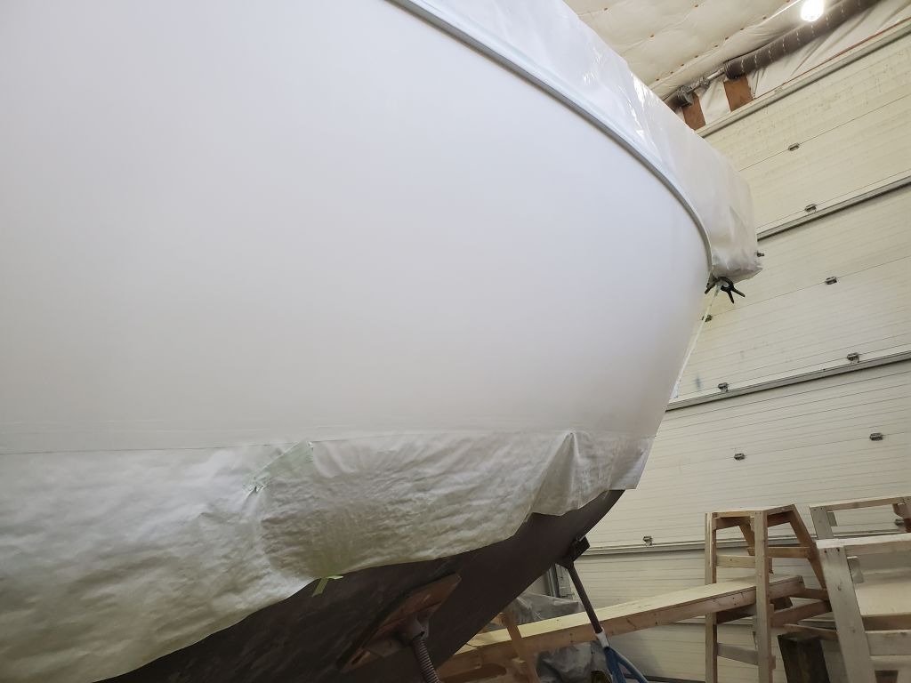
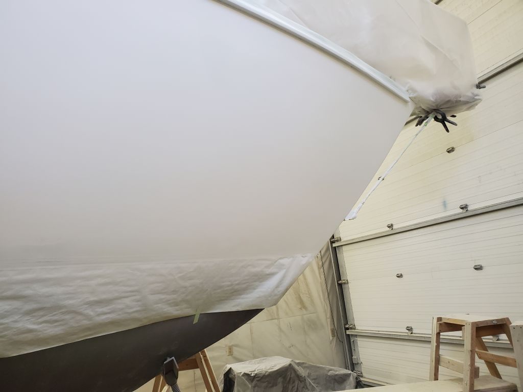
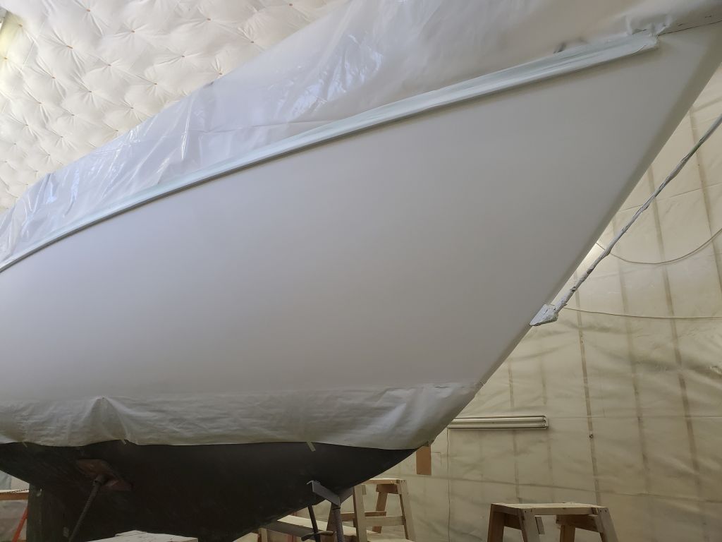
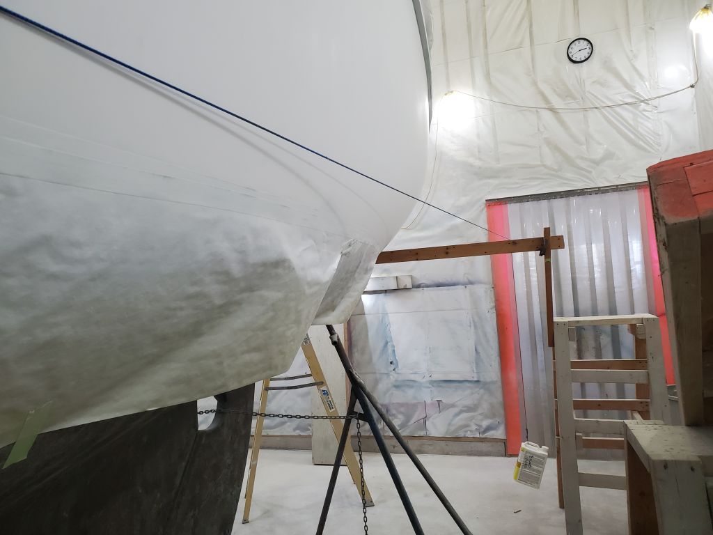
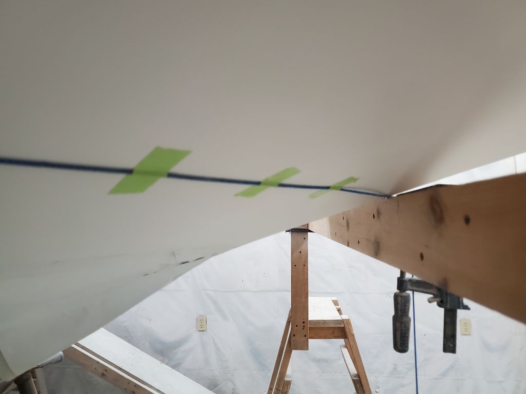
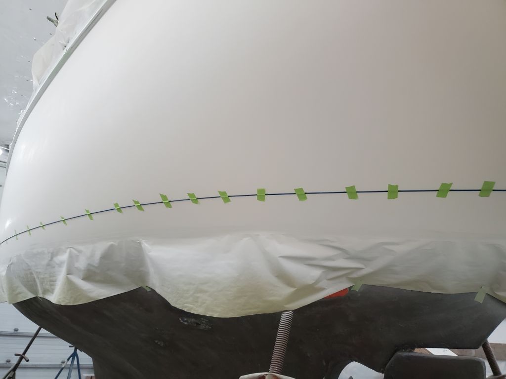
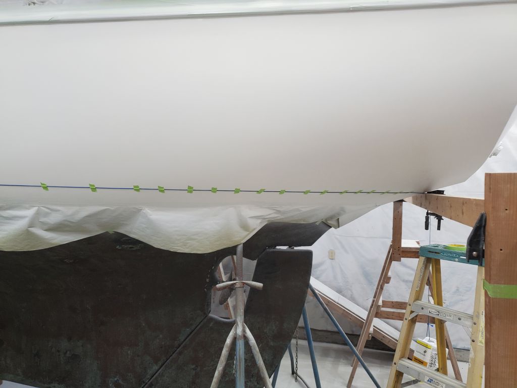
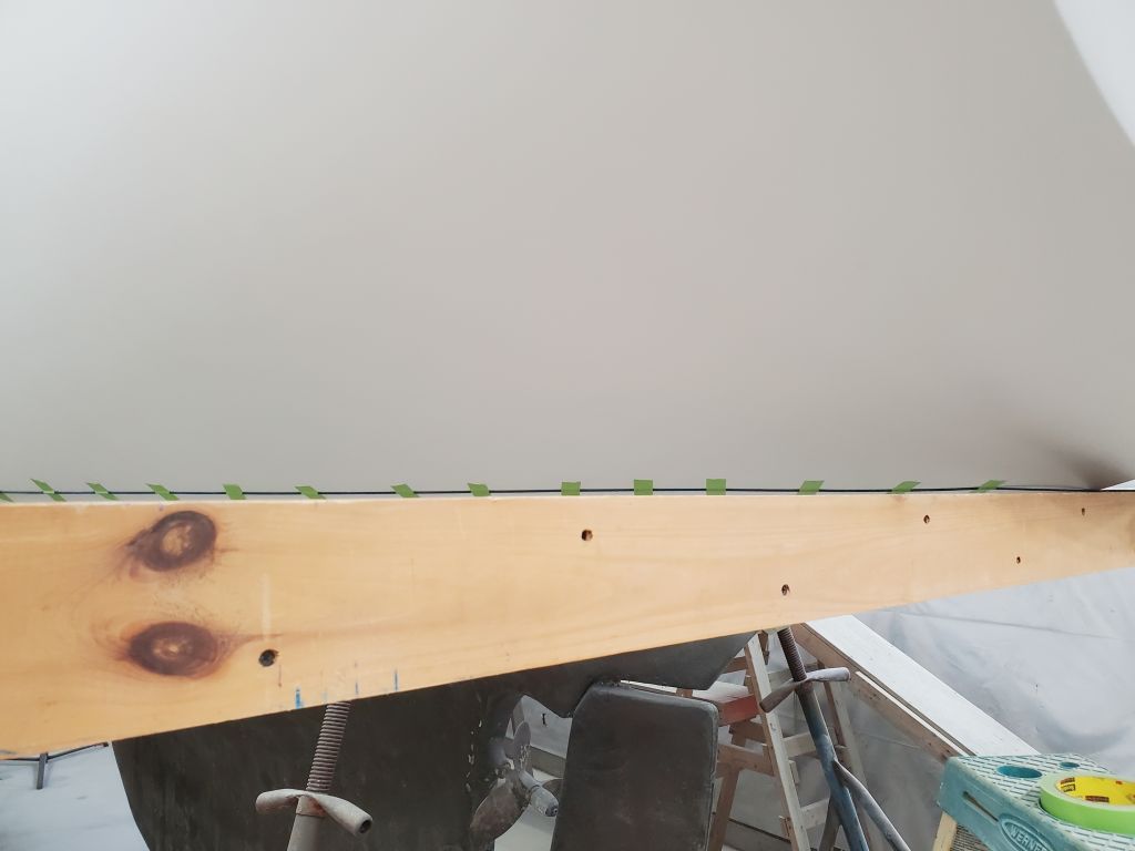
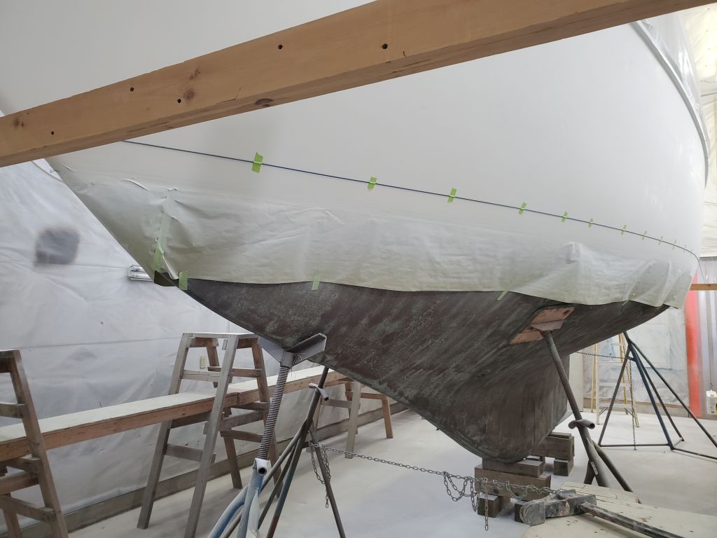
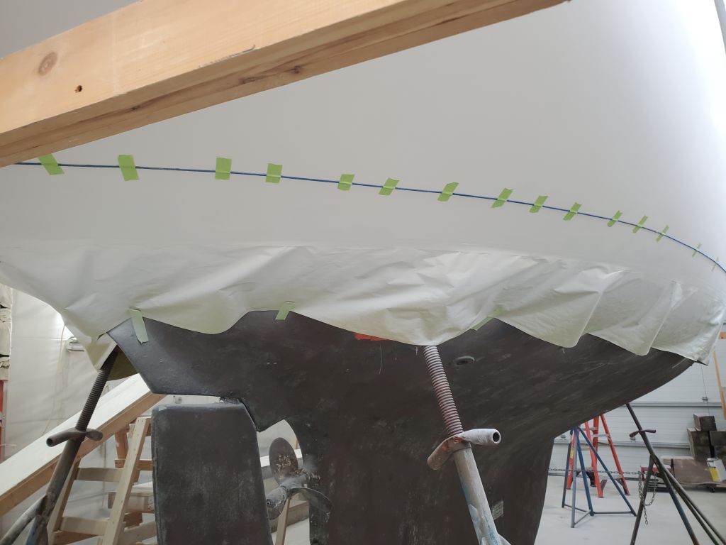
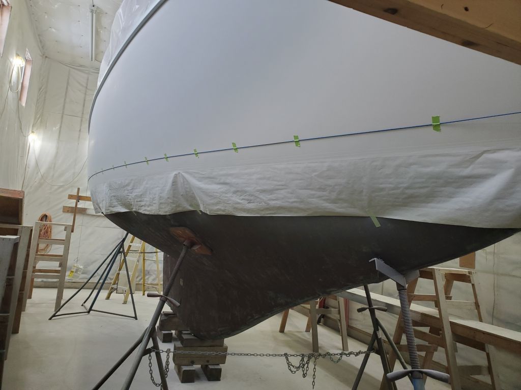
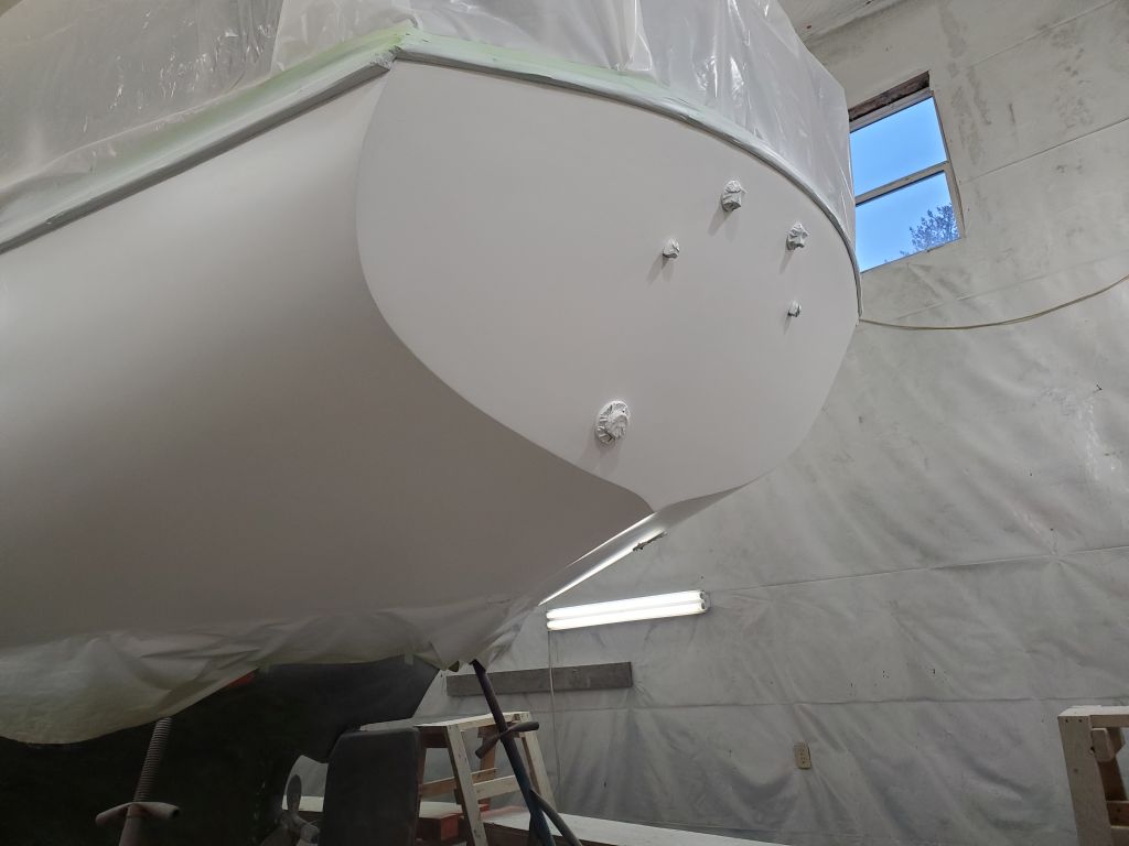
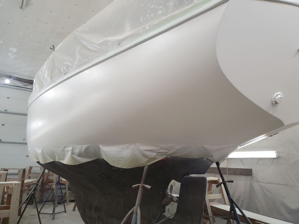
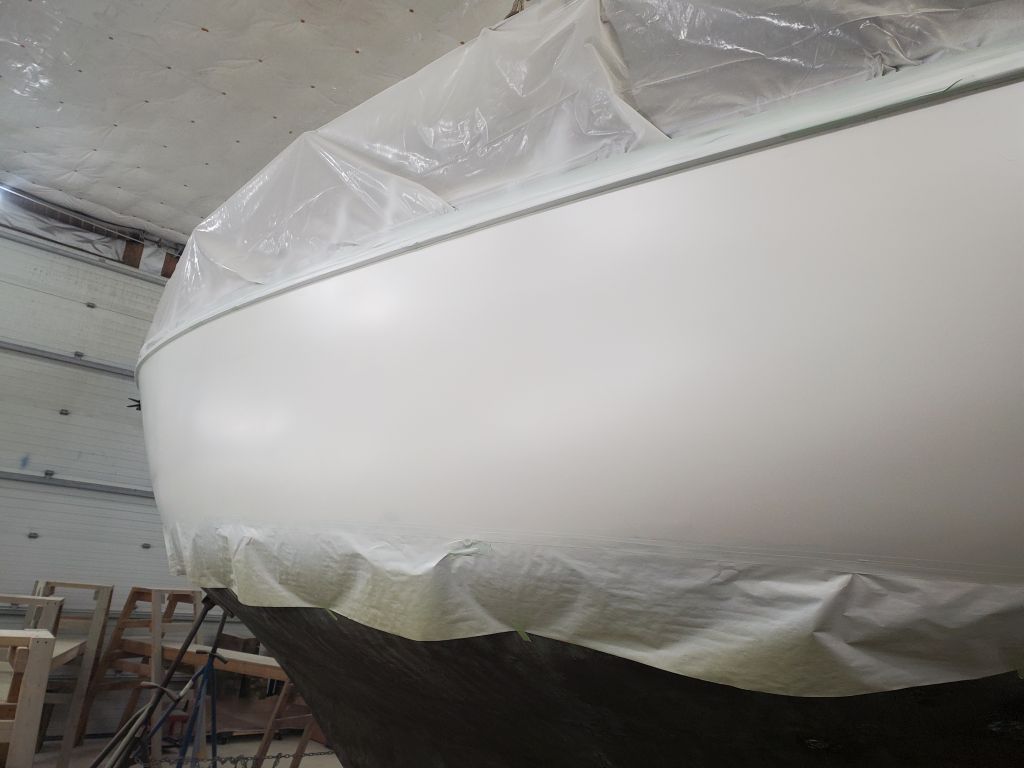
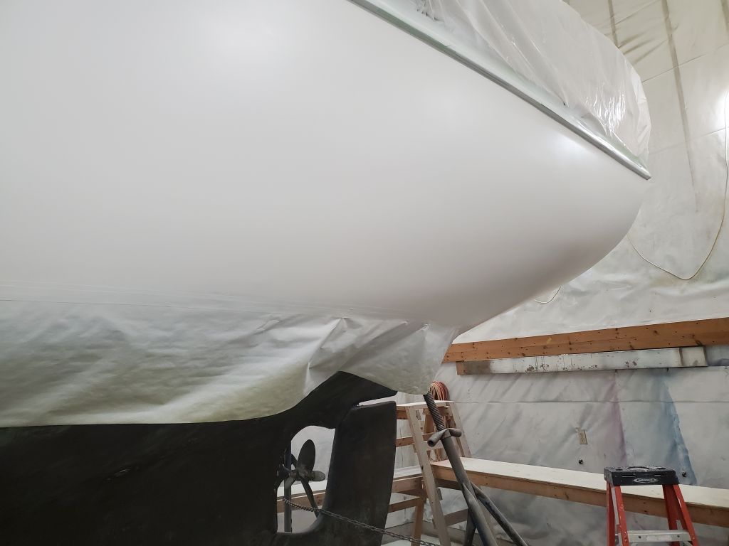
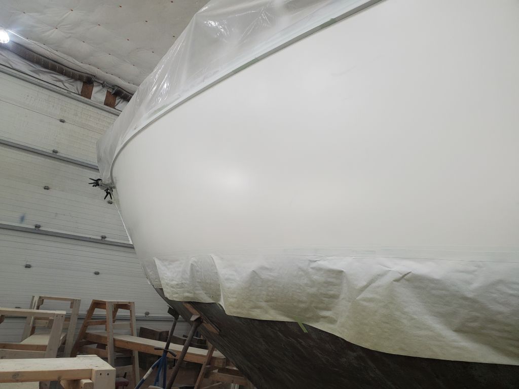
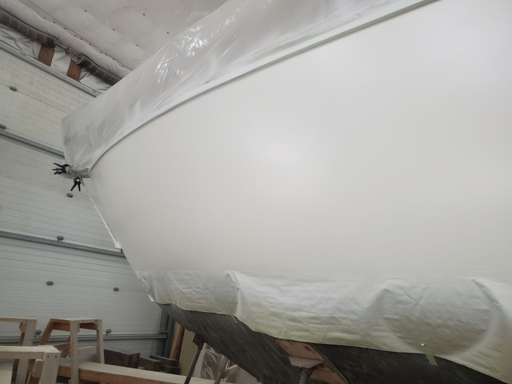
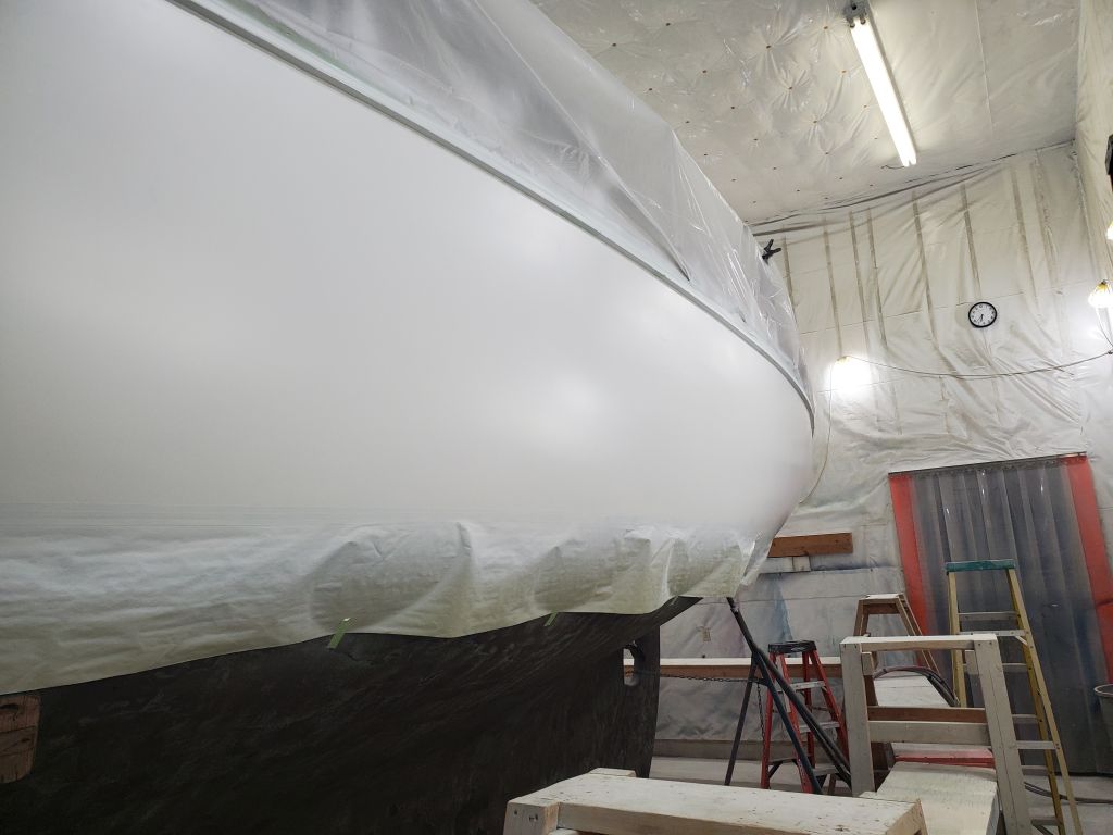
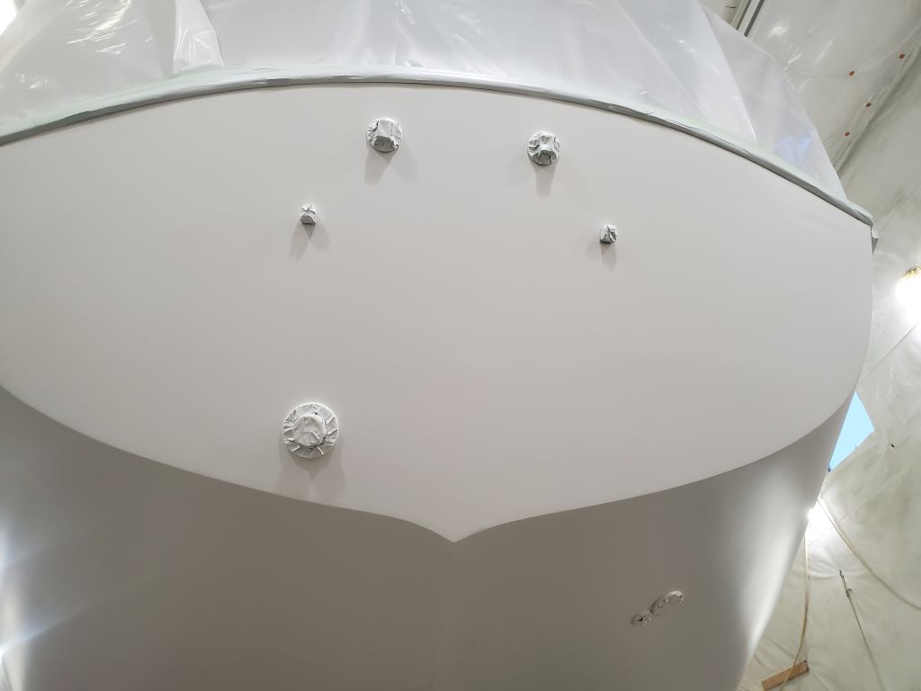
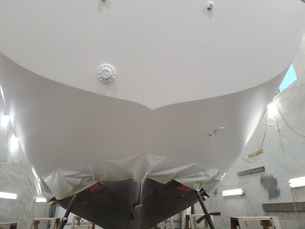
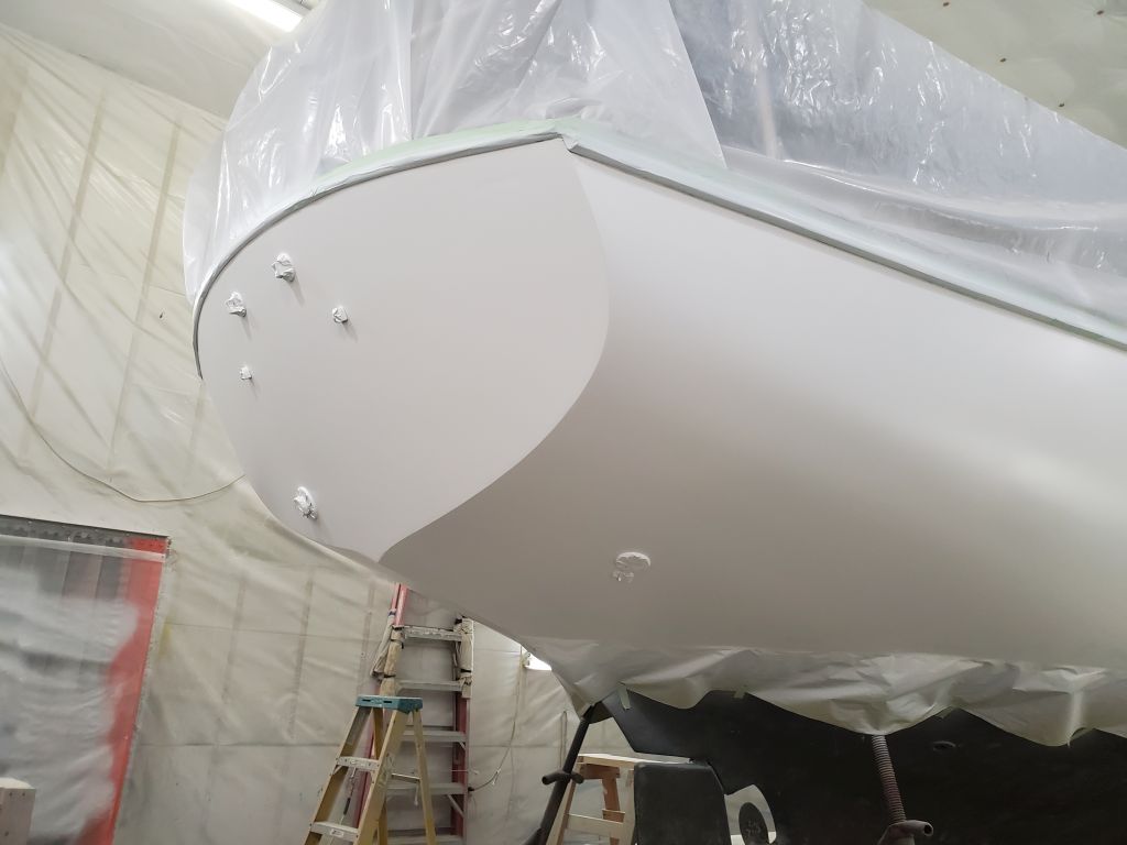
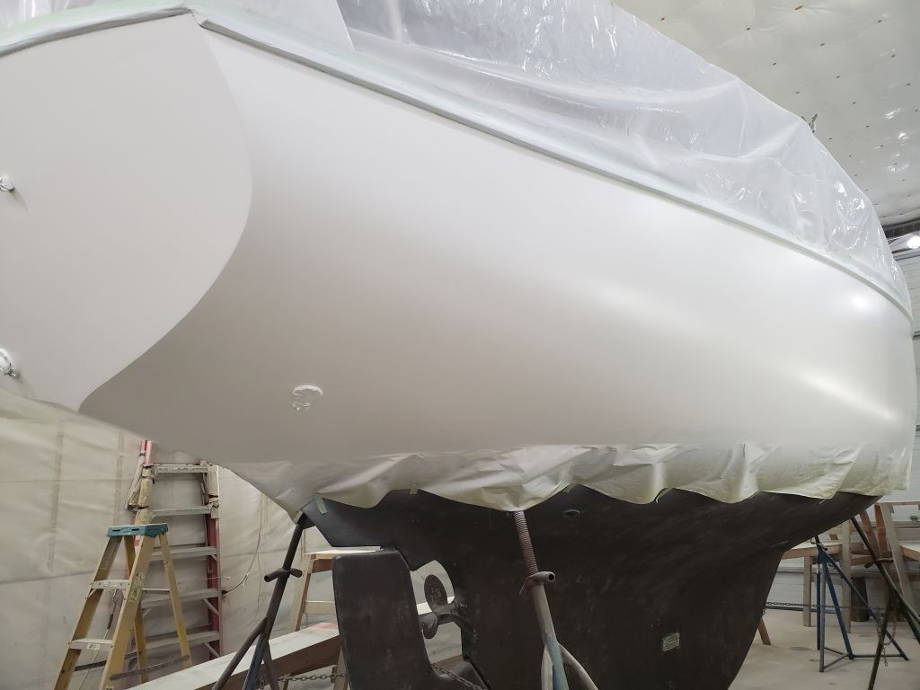
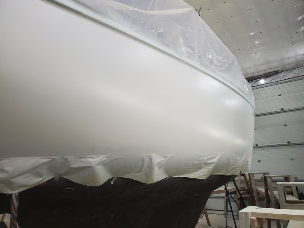
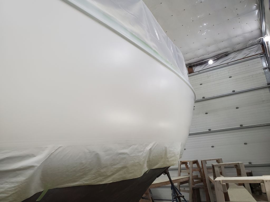
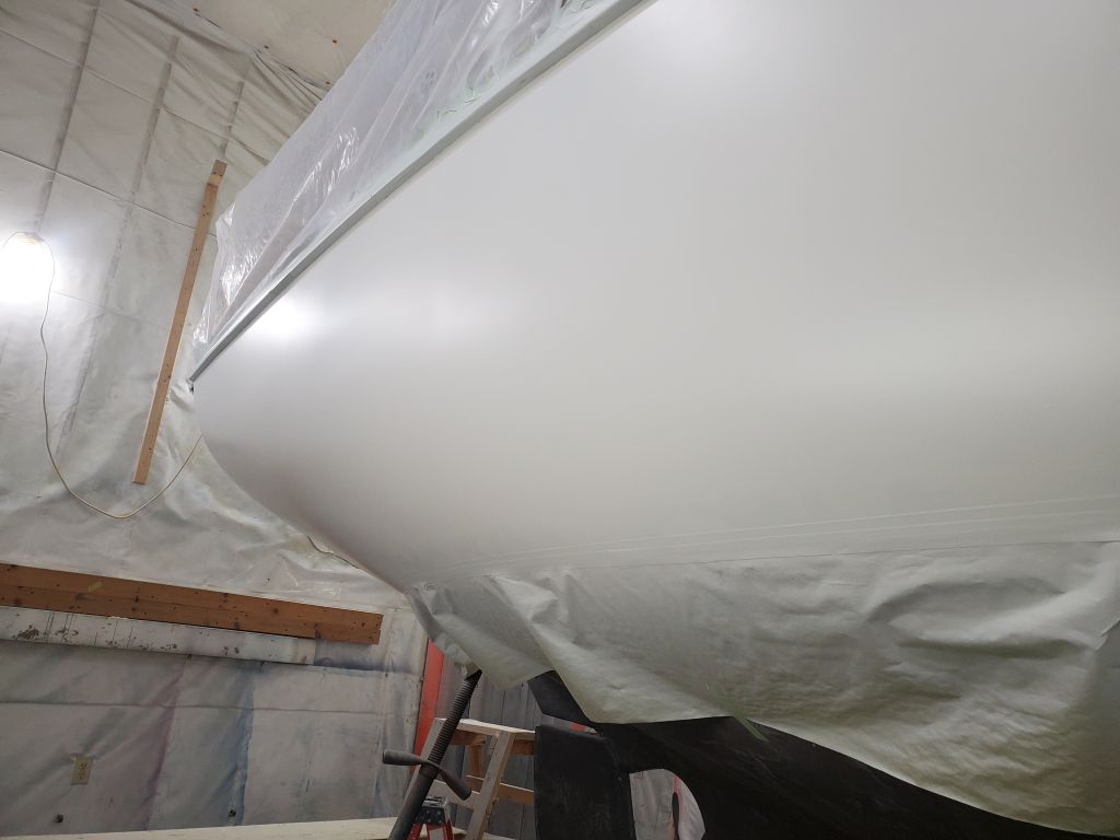
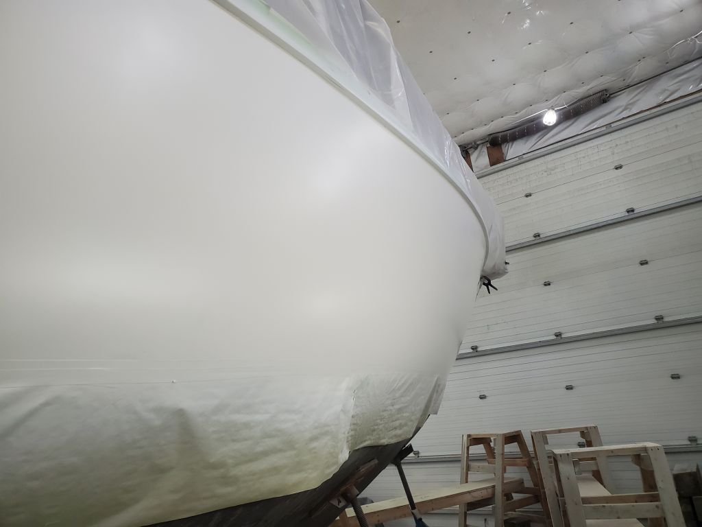
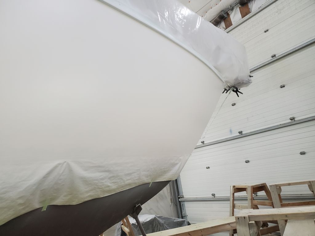
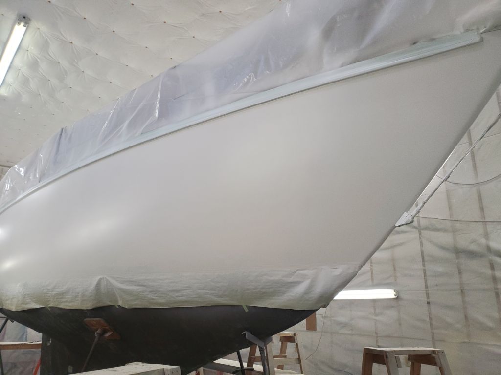
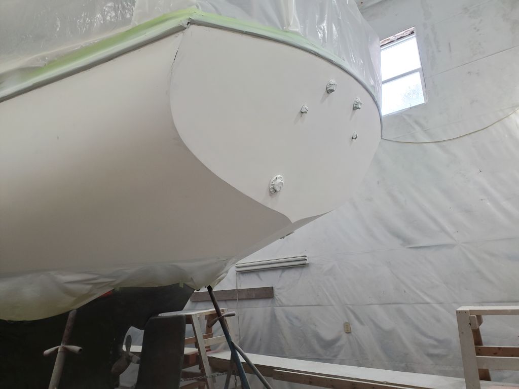
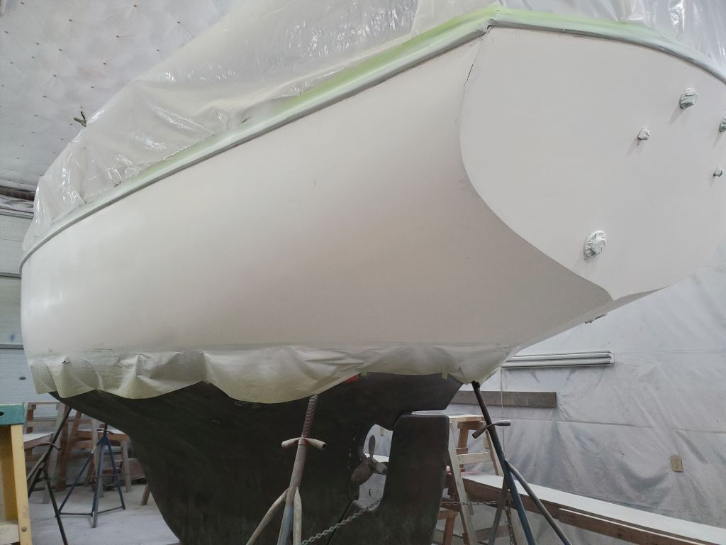
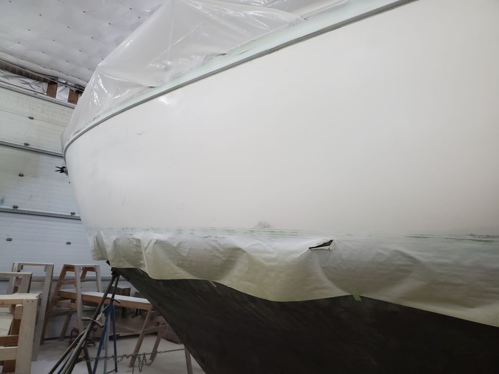
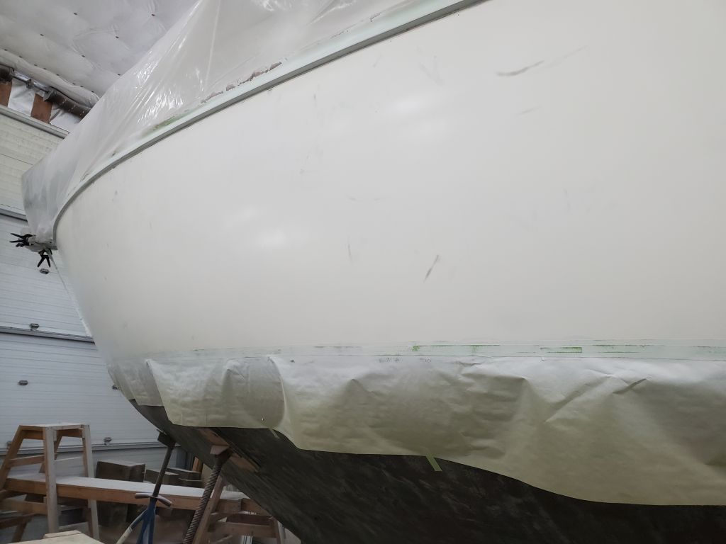
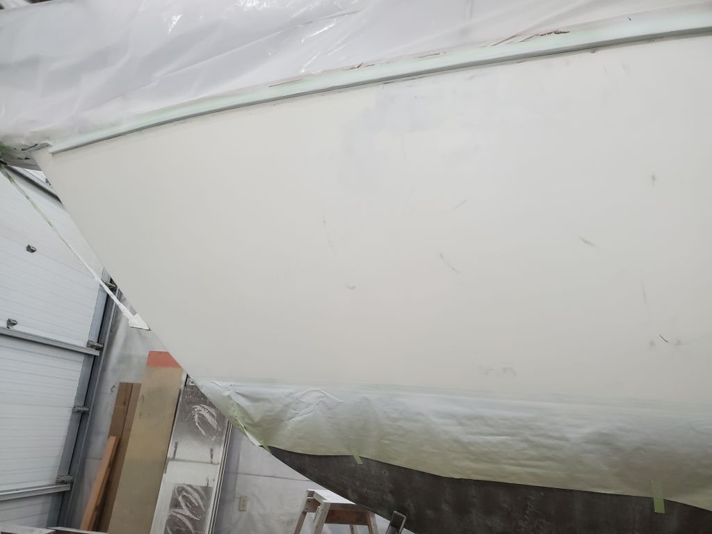
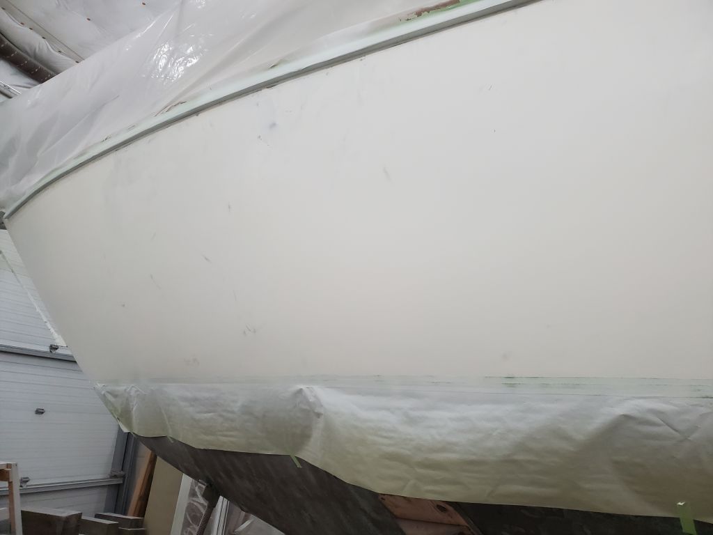
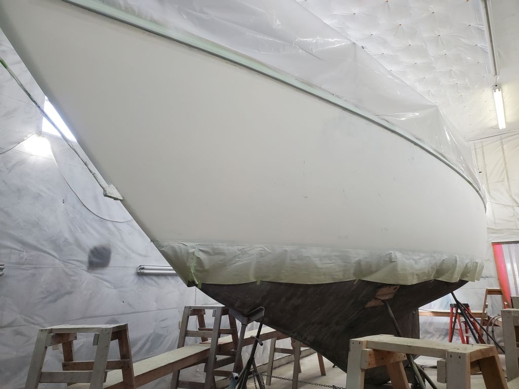
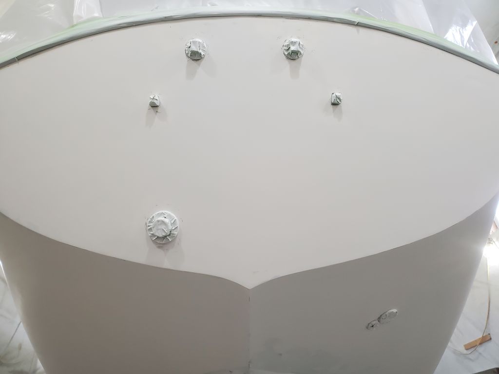
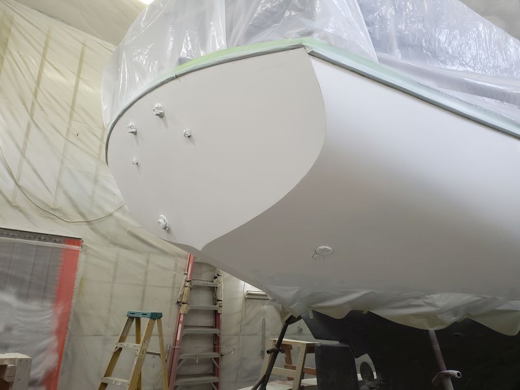
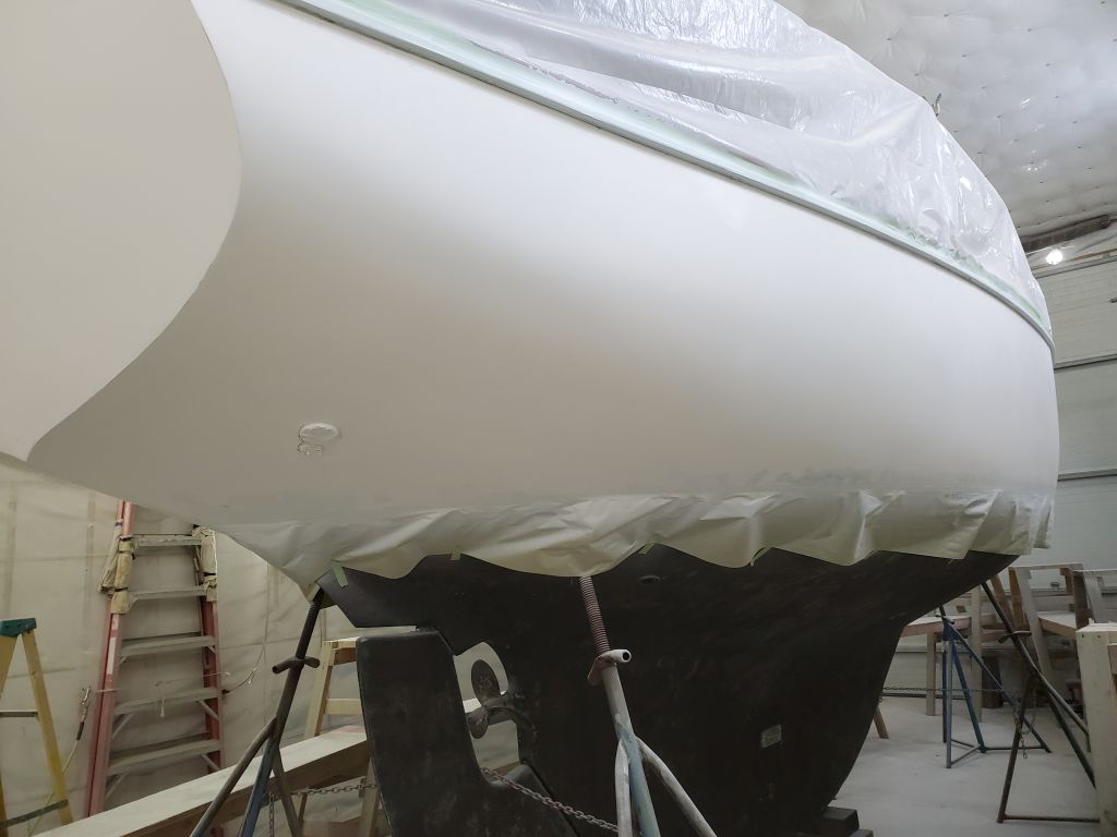
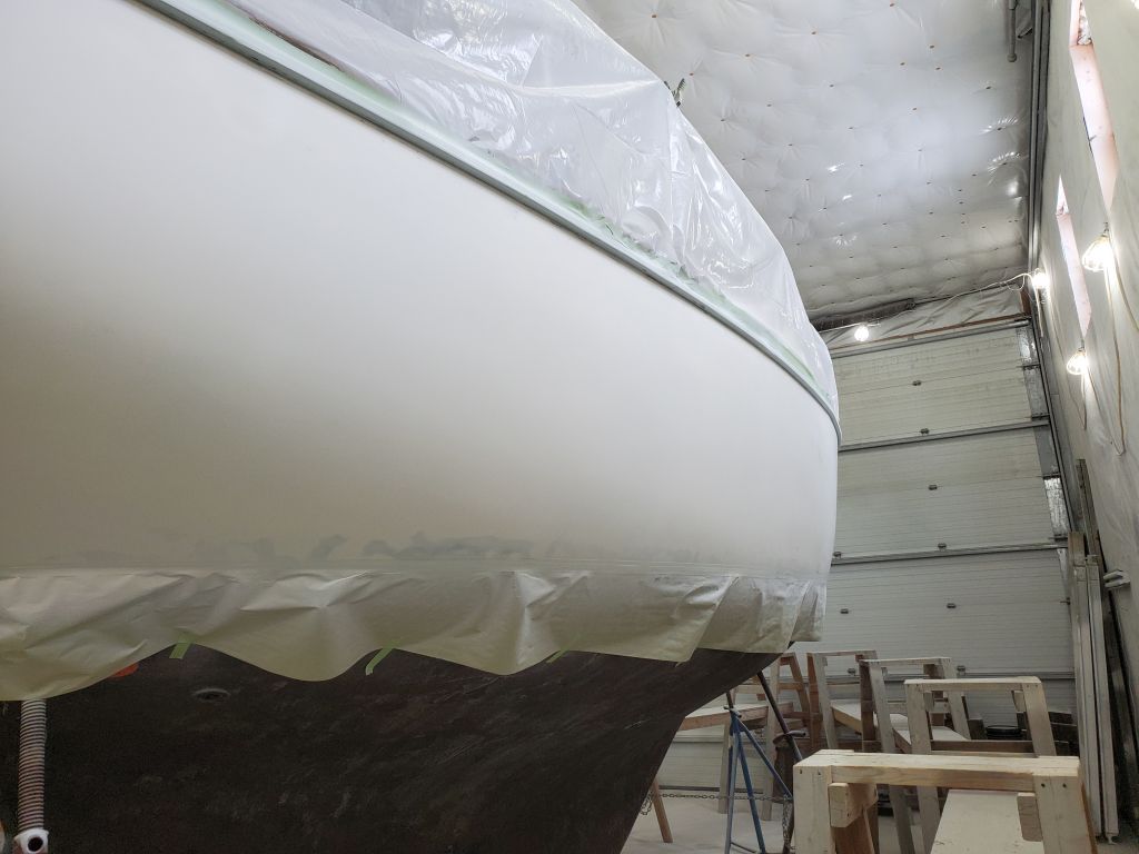
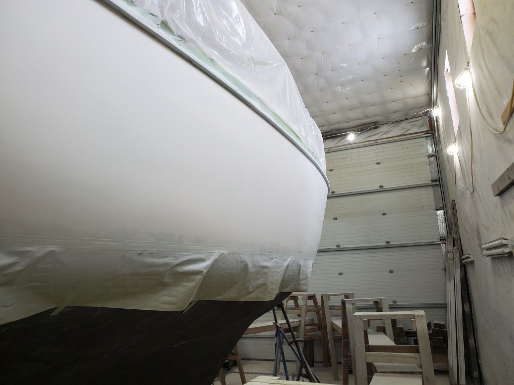
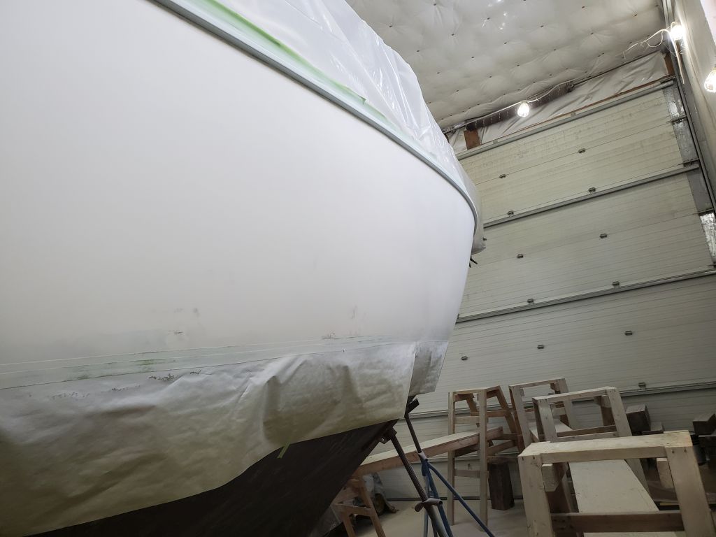
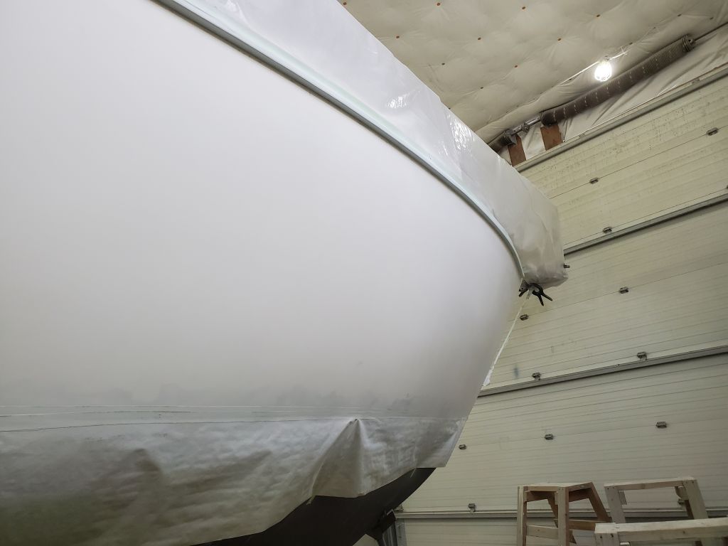
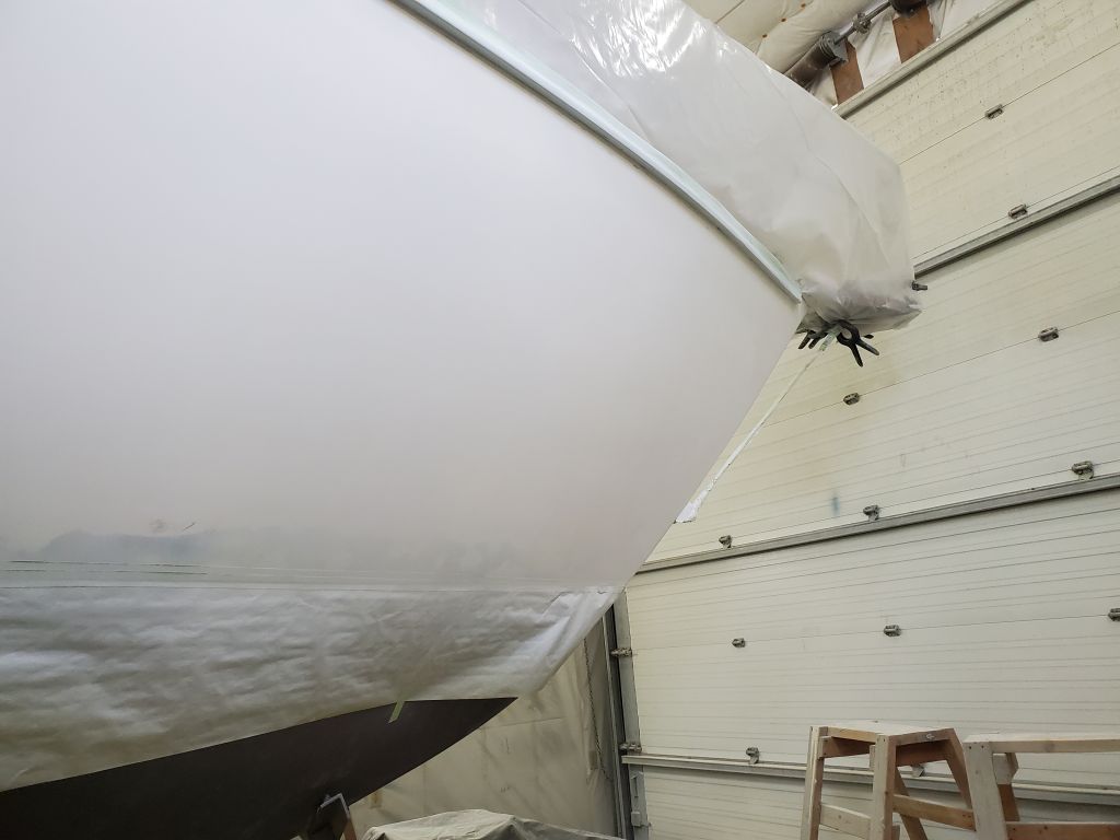
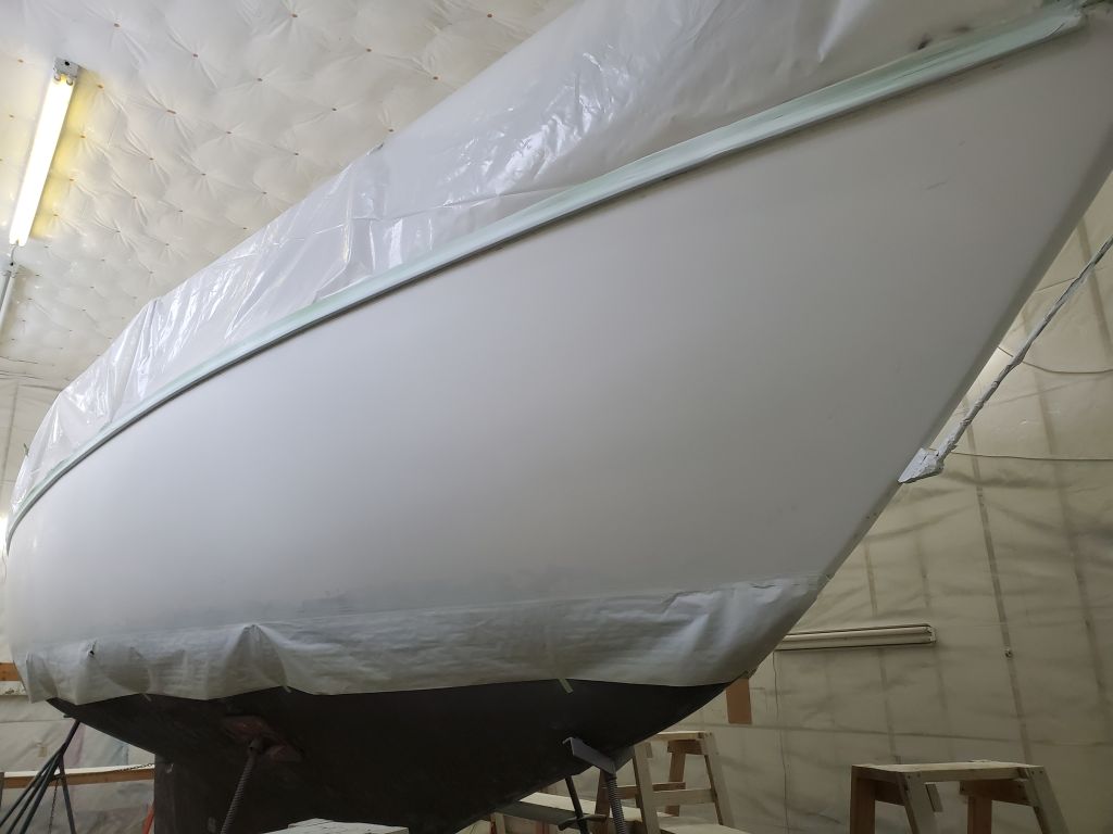
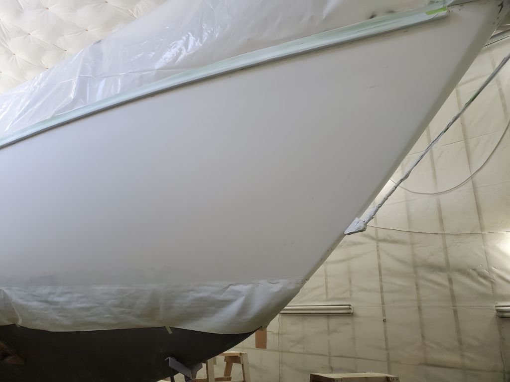
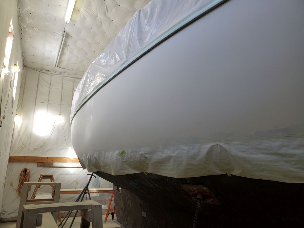
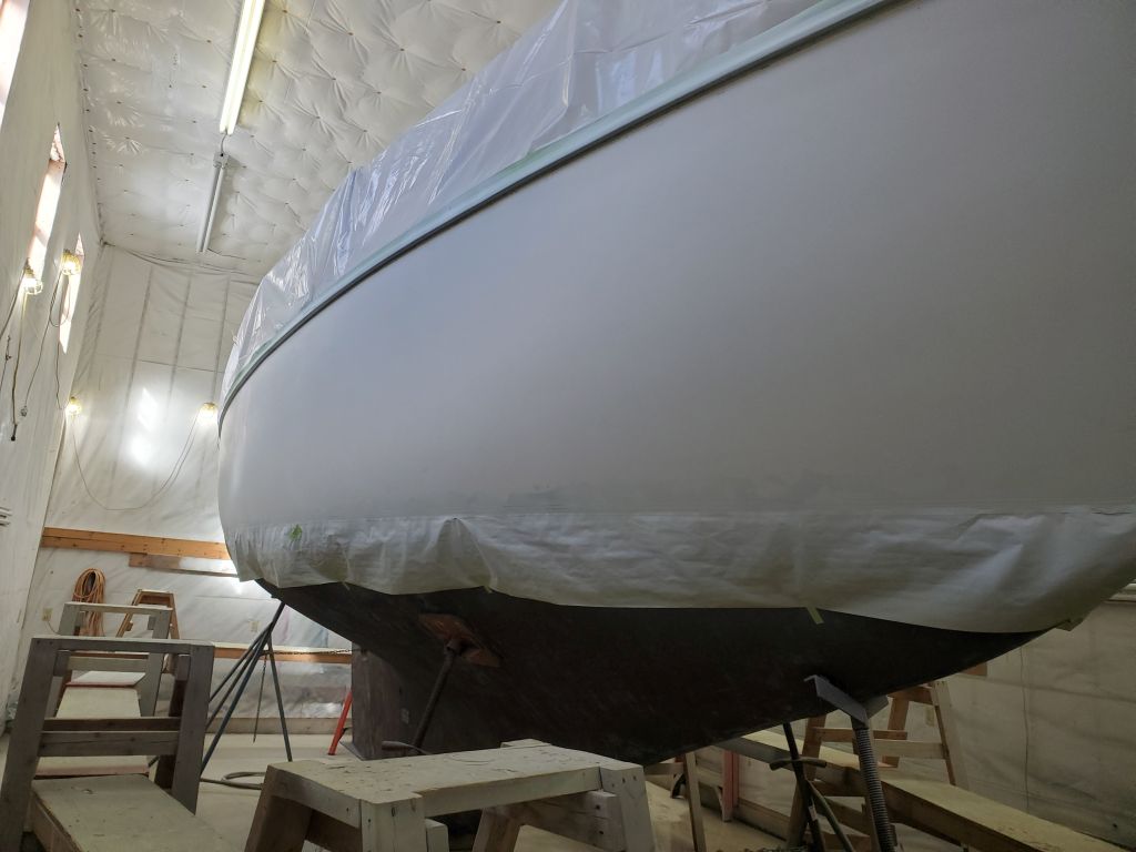
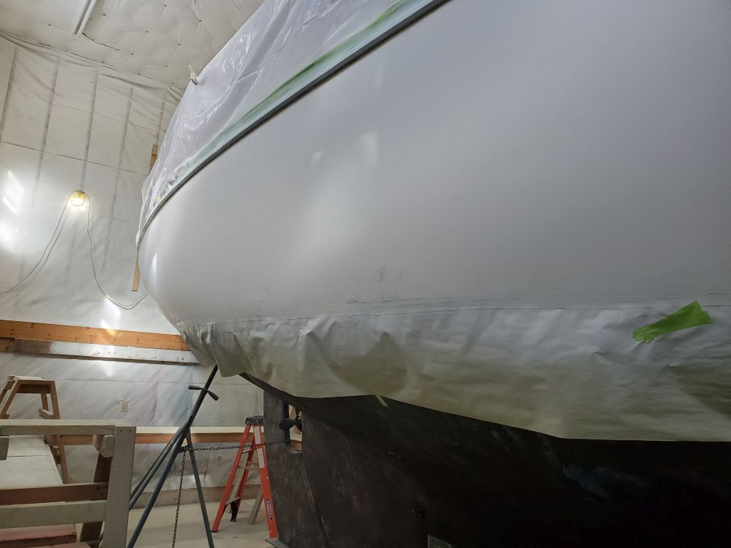
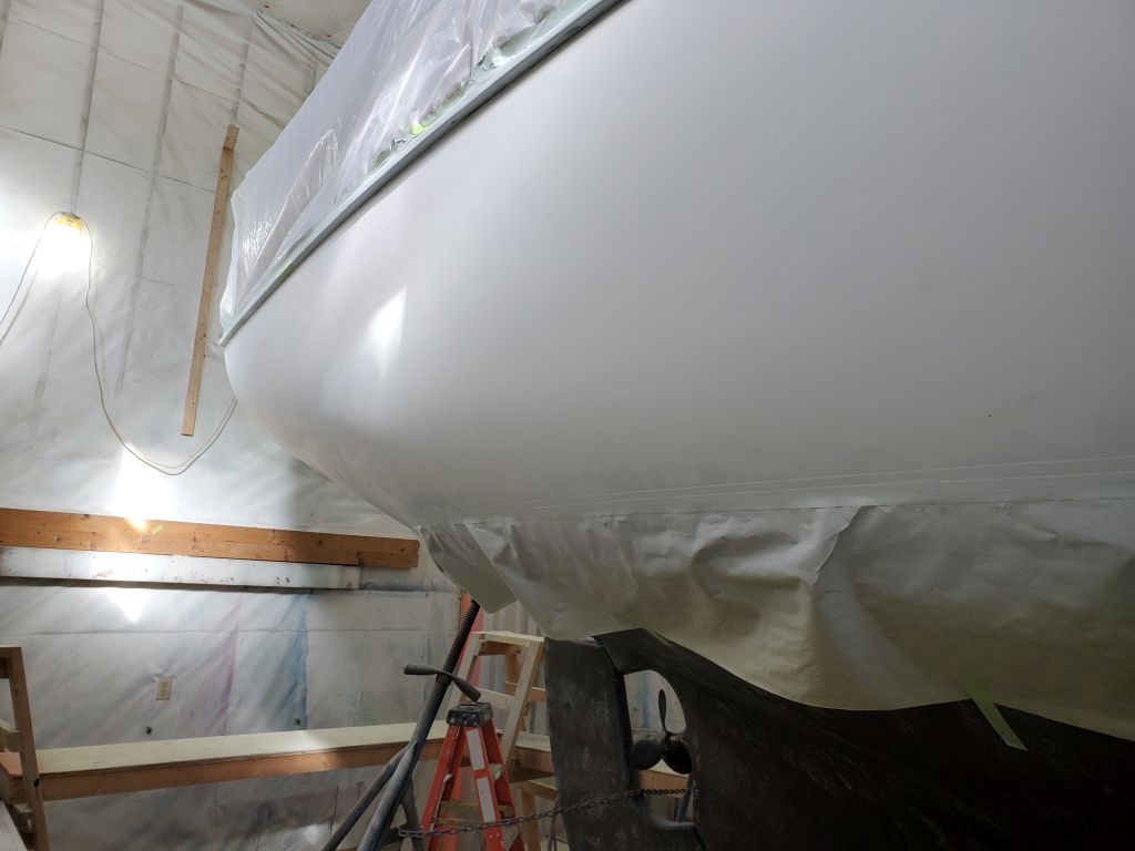
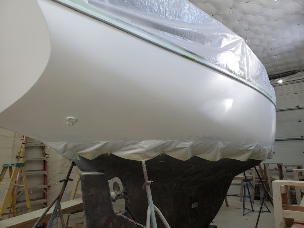
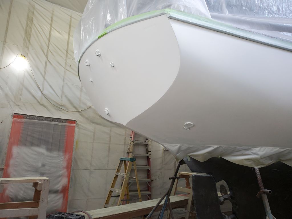
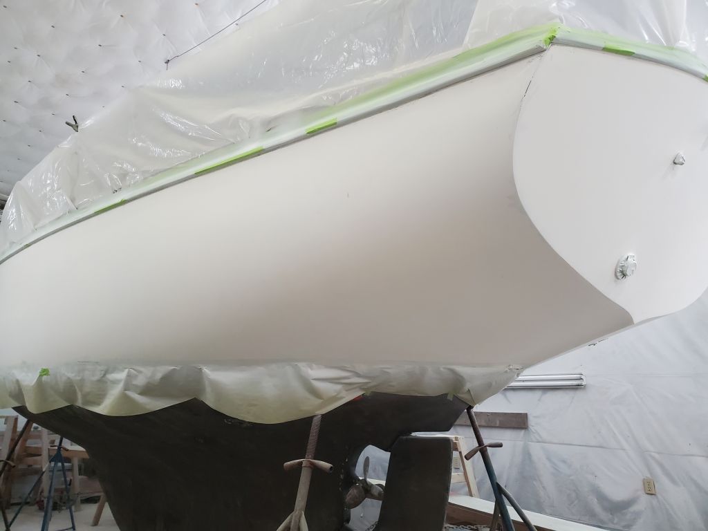
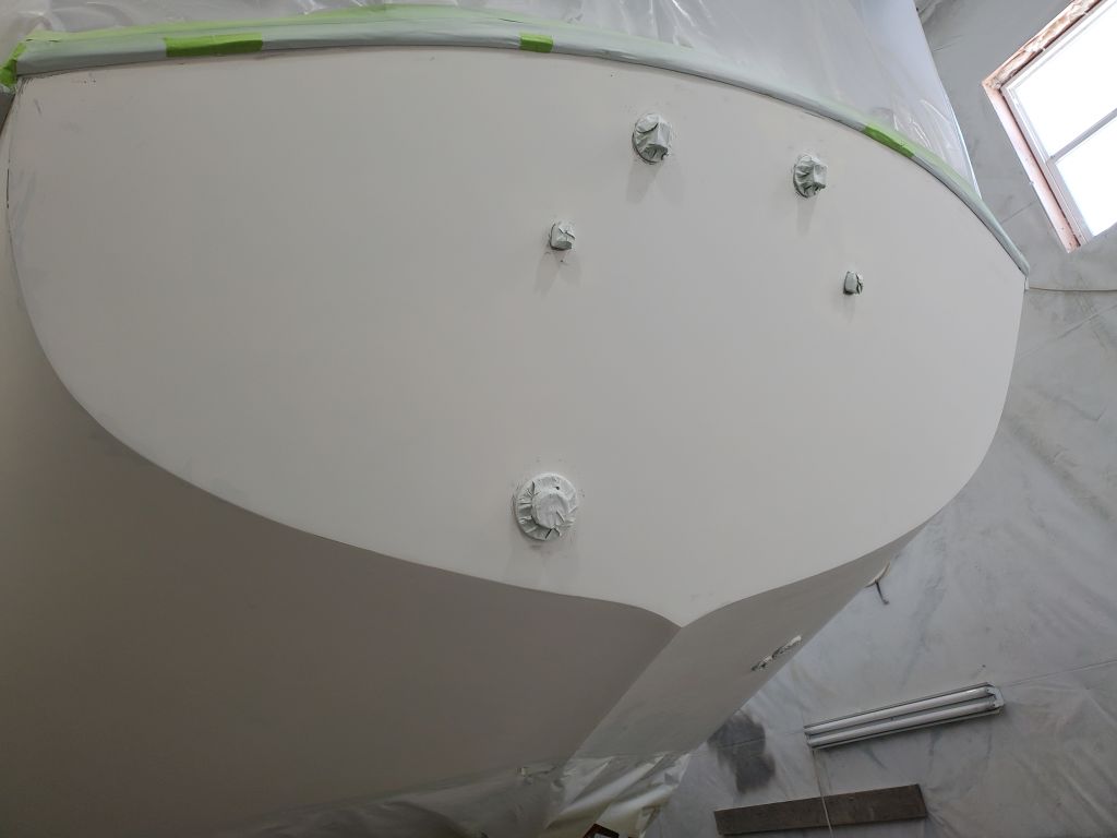
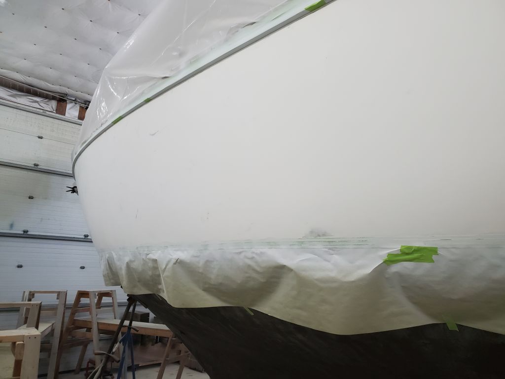
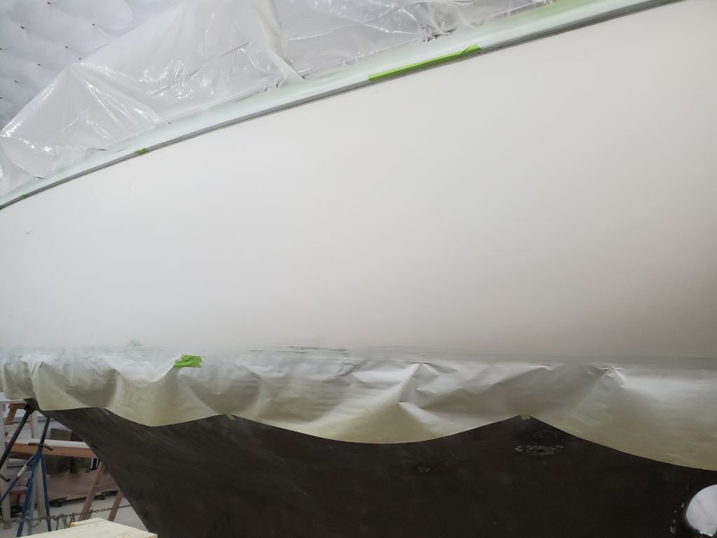
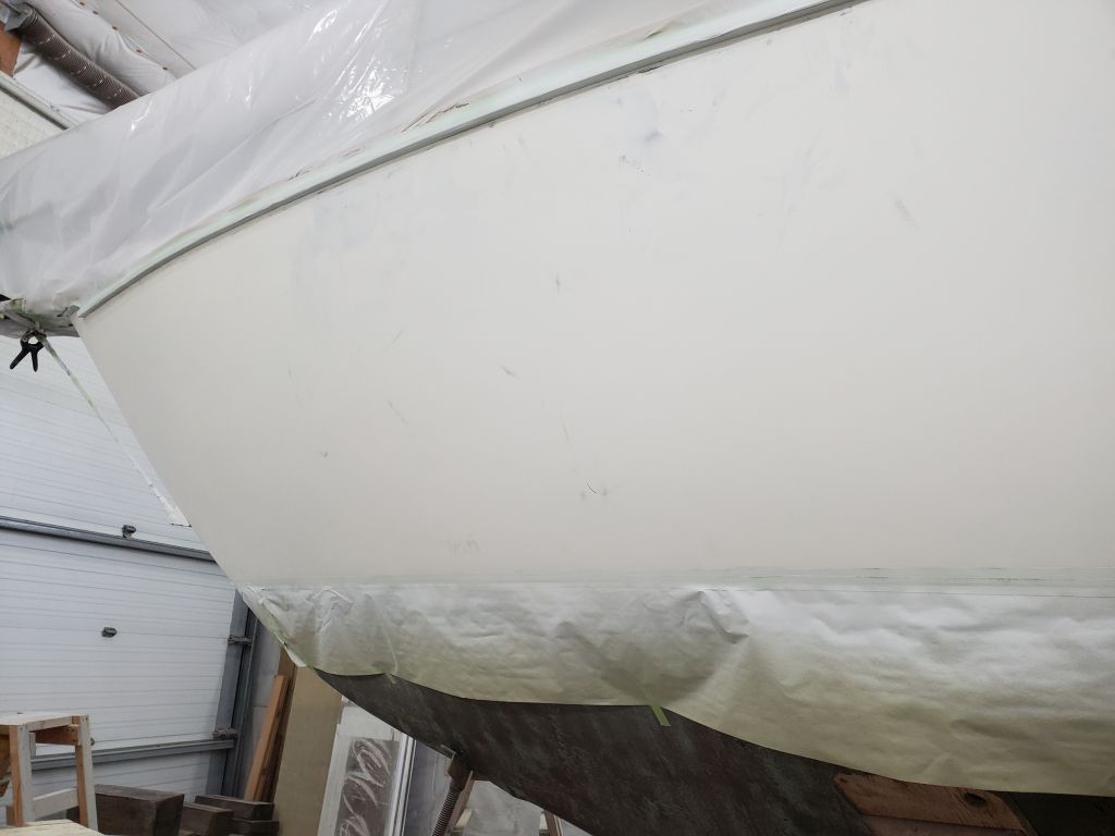
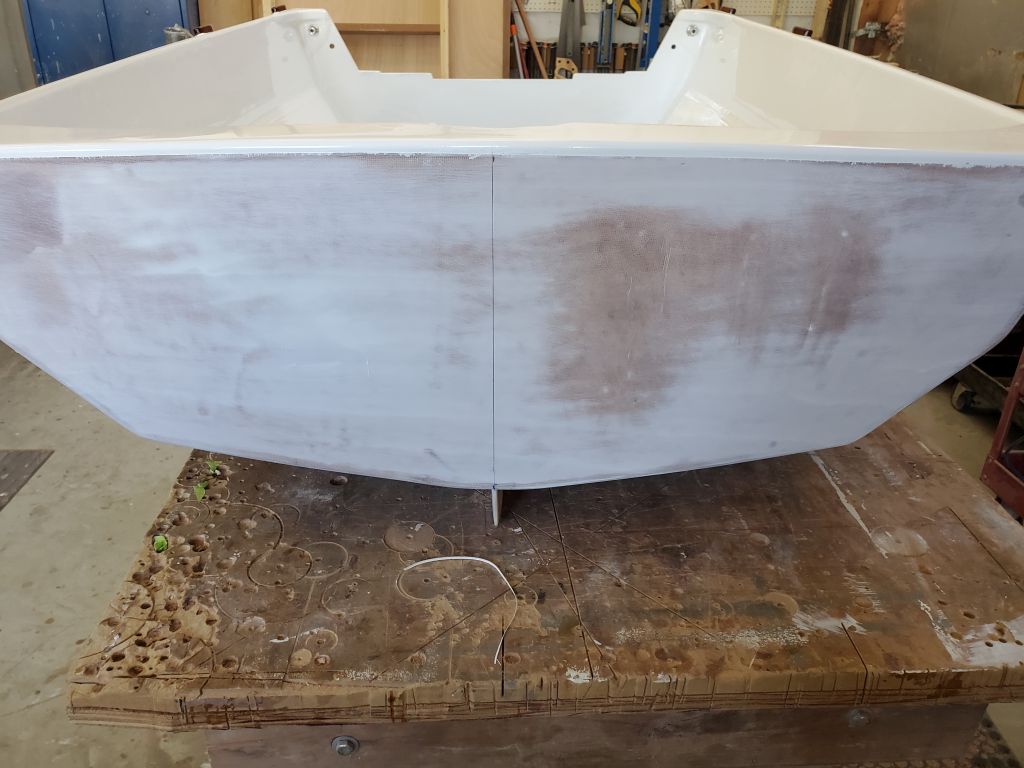
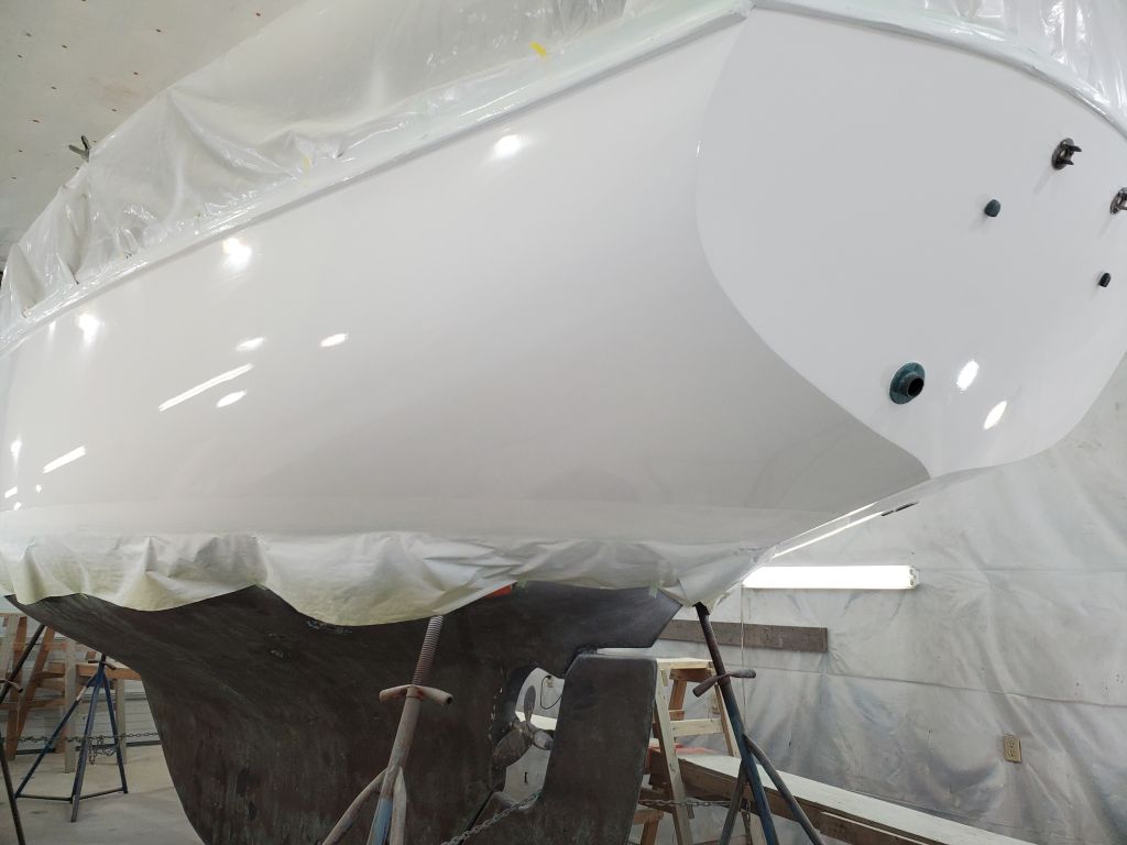
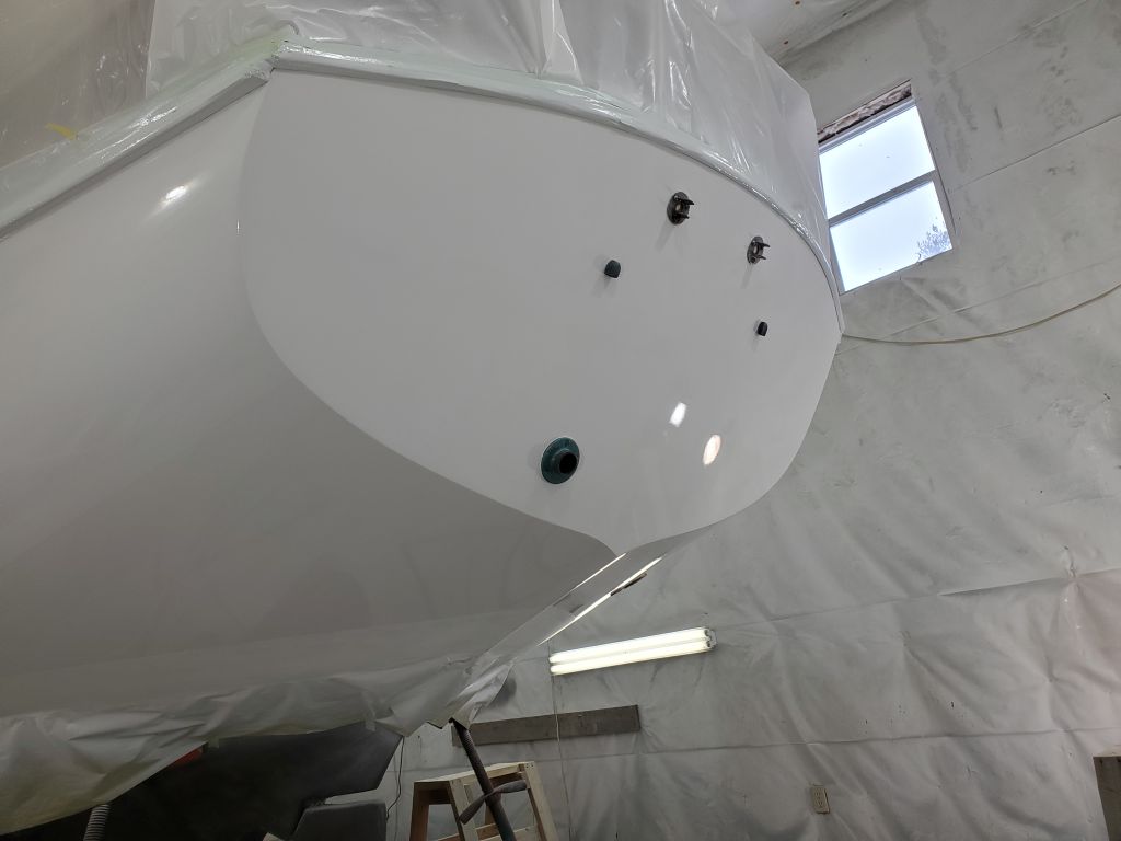
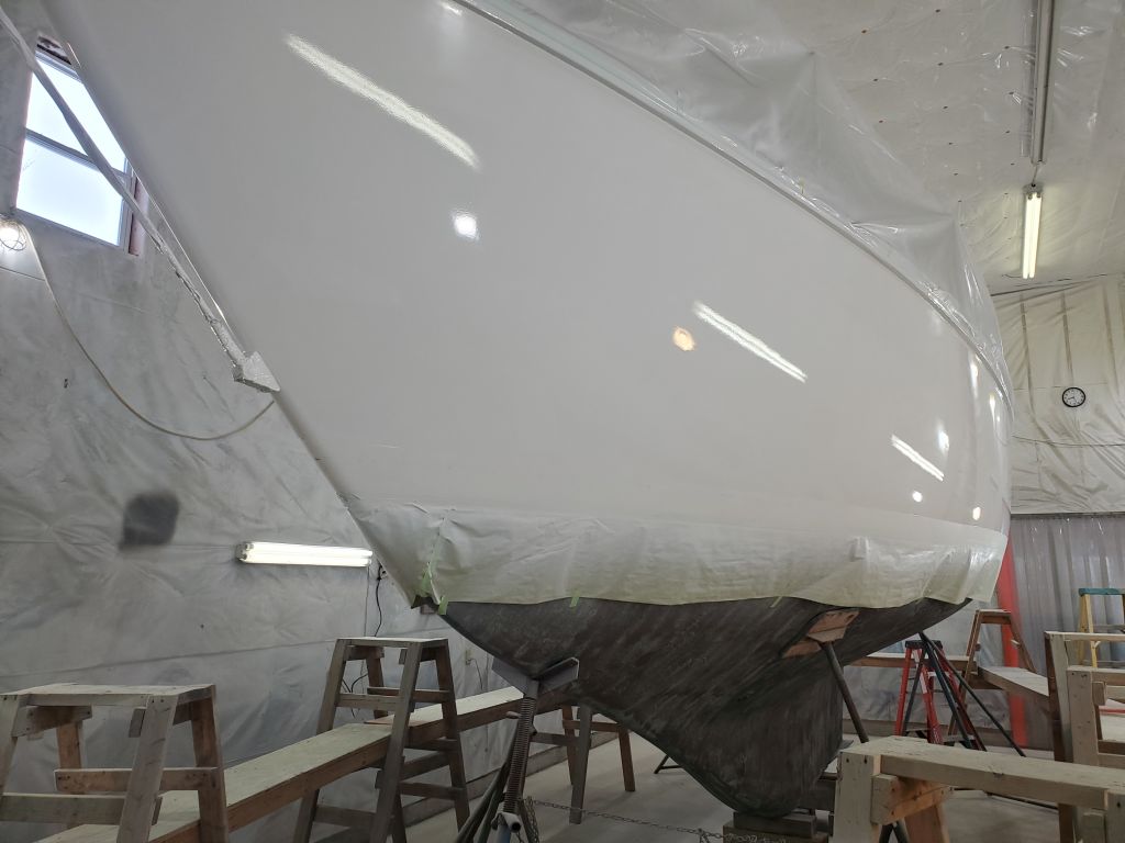
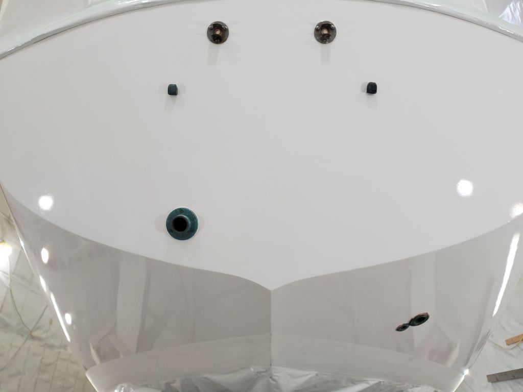
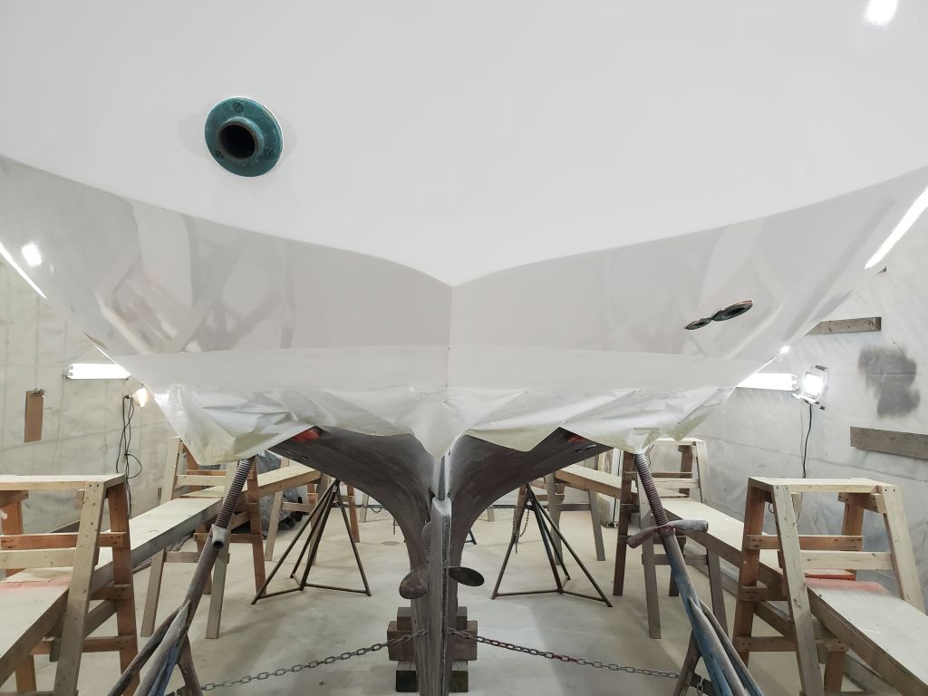
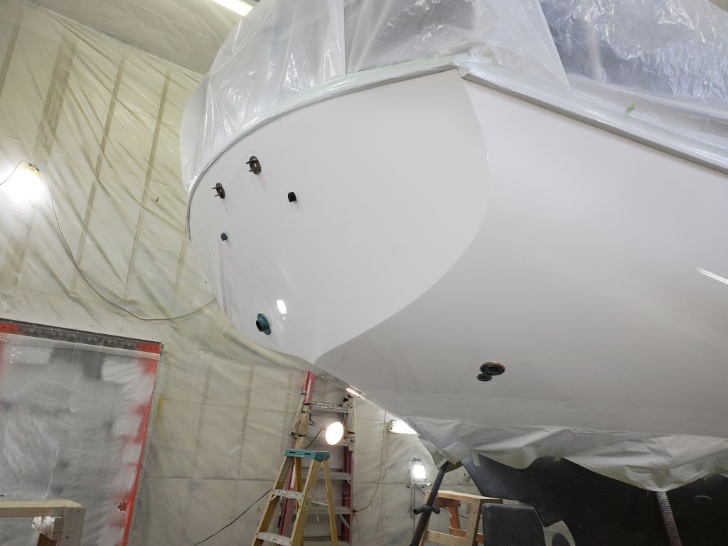
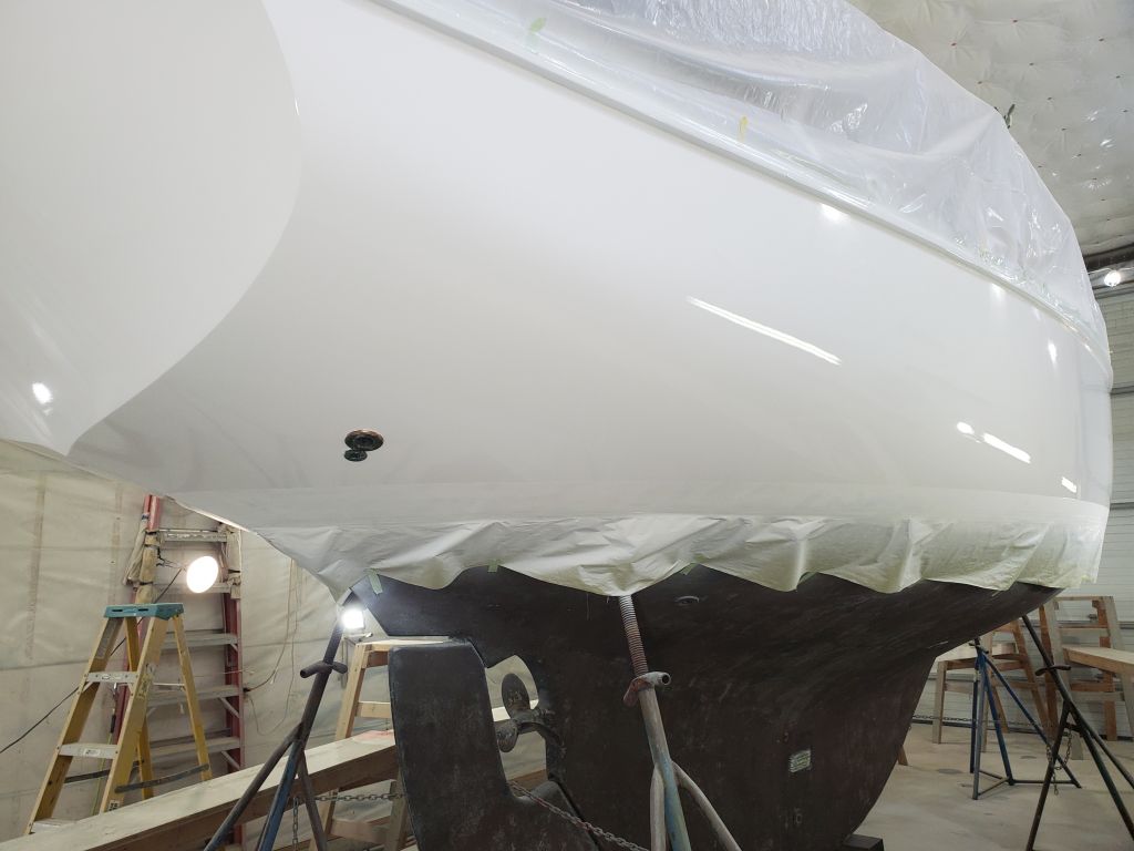
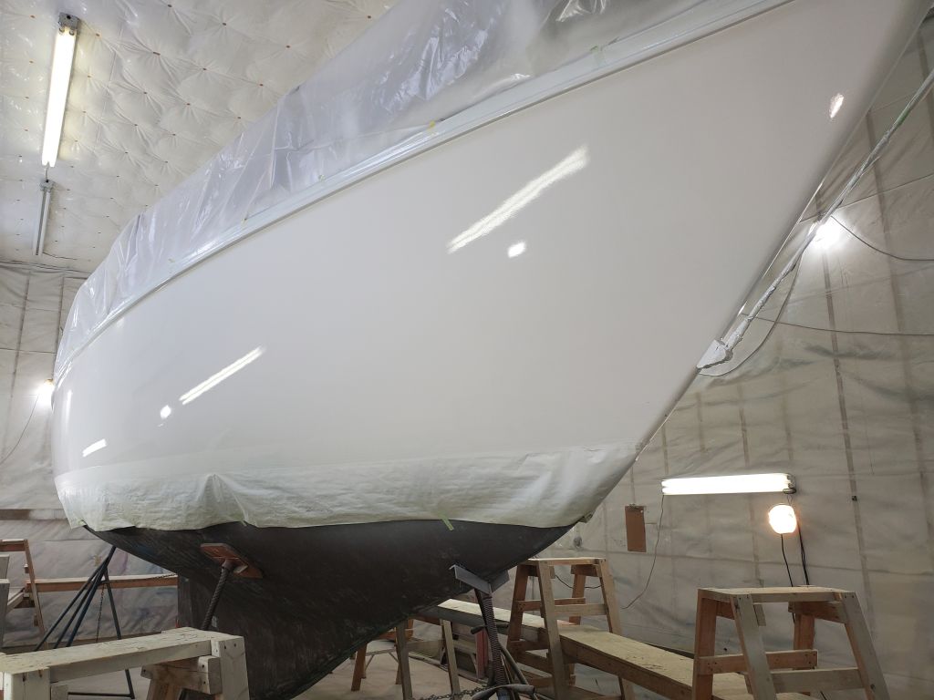
I cleaned up and reassembled the spray gun, which I’d left soaking overnight, and then removed what masking I could from the hull, mainly the various hardware and through hulls on the transom and counter. I removed the masking paper and tape from the top edge of the boottop area. For now, this was all I could do on the hull itself, as I needed to give the fresh paint additional cure time before masking over the topsides to spray the boottop.
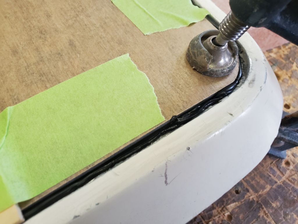
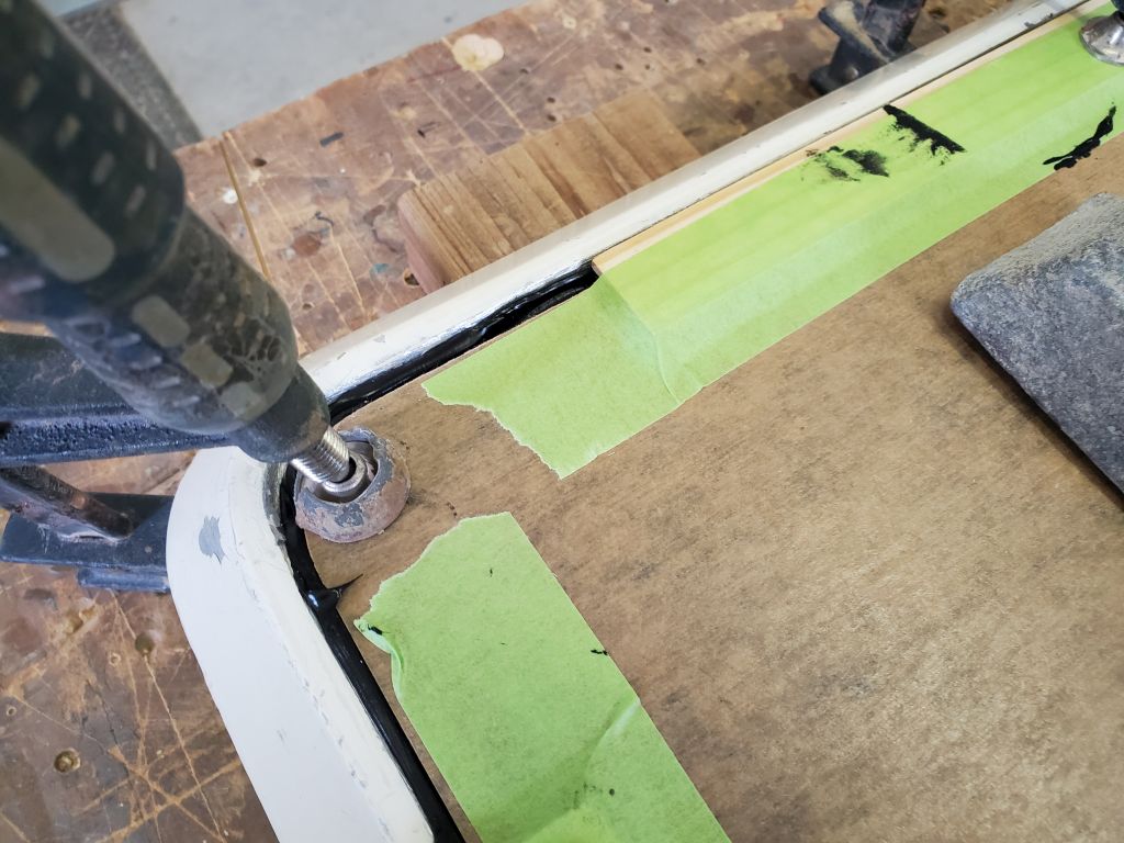
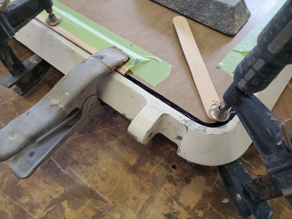
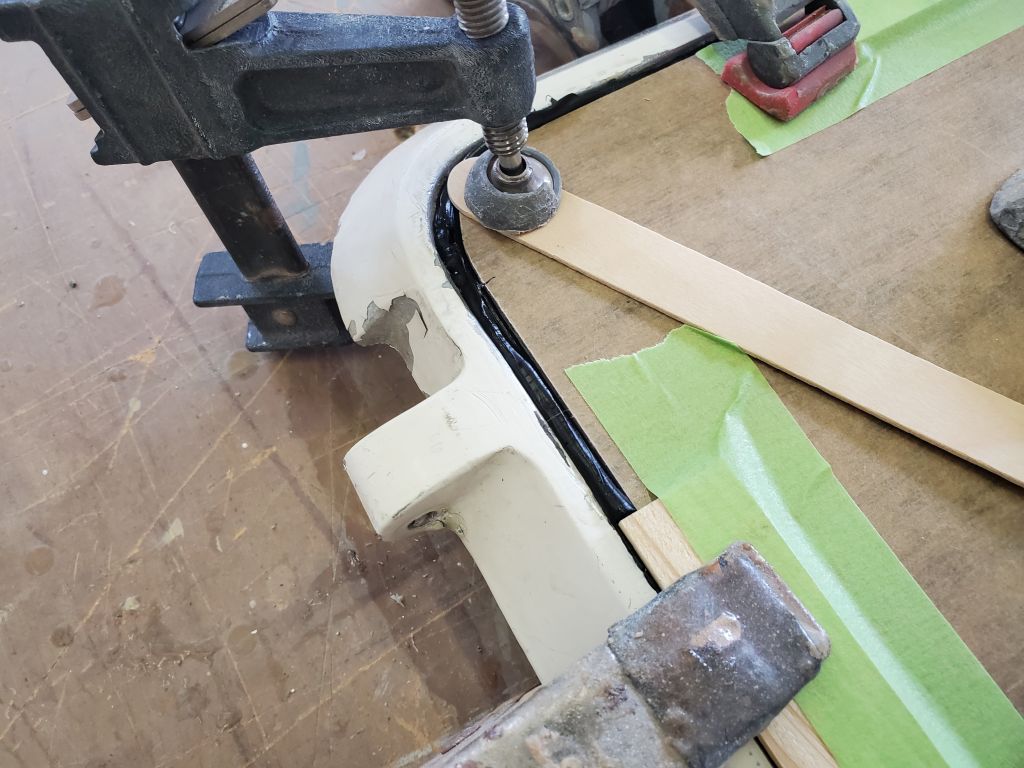
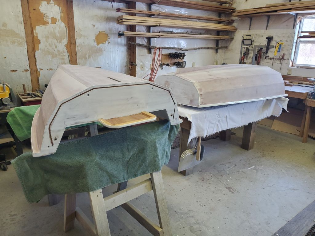
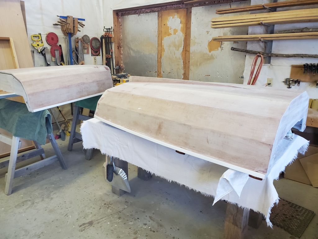
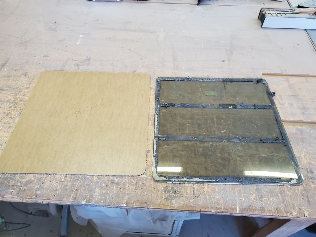
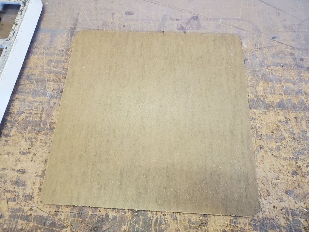
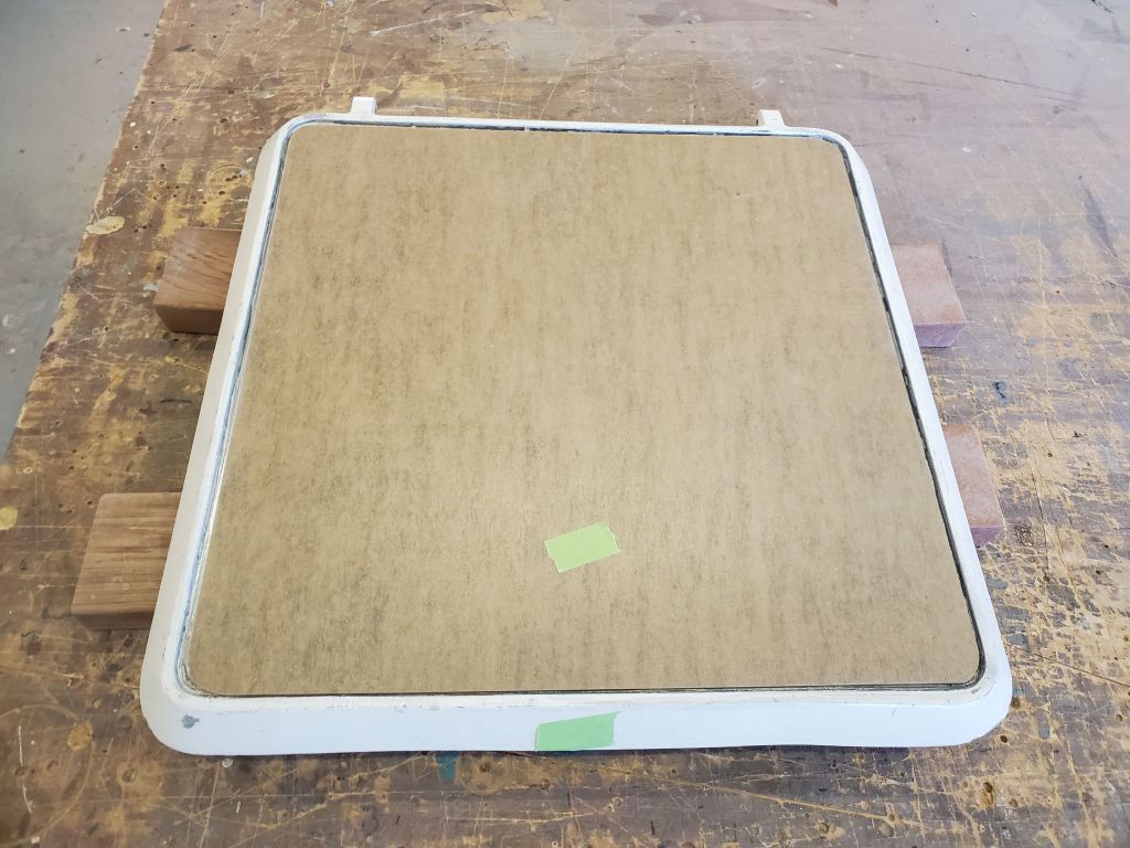
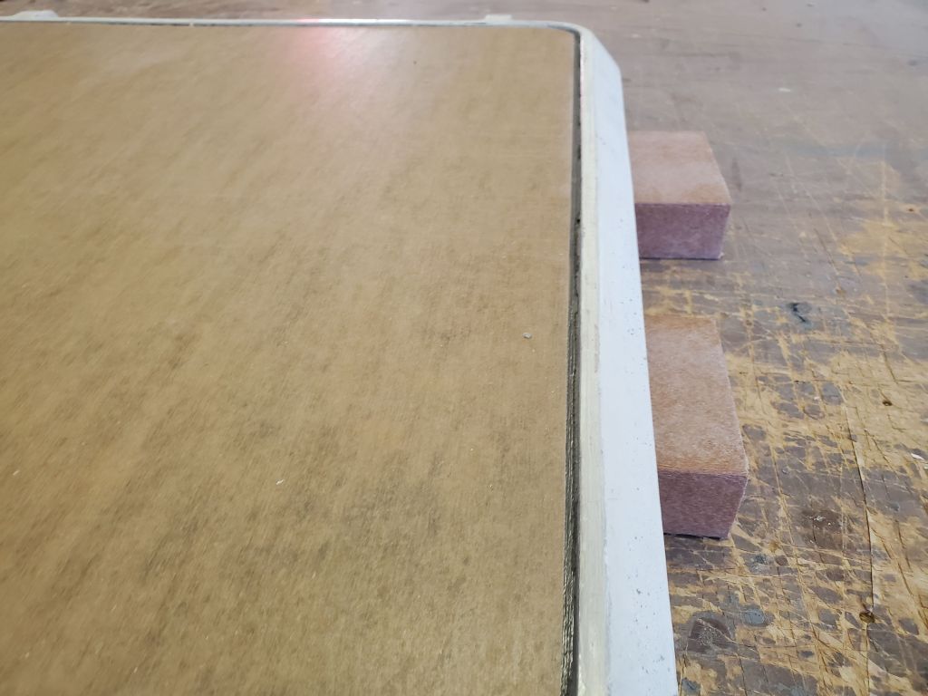
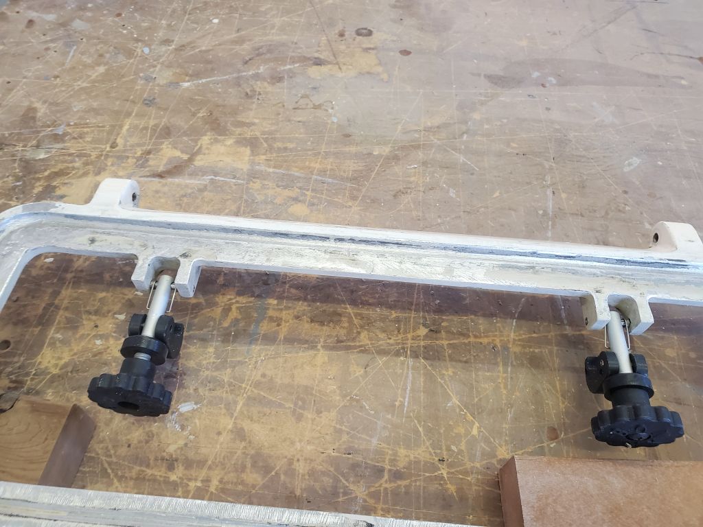
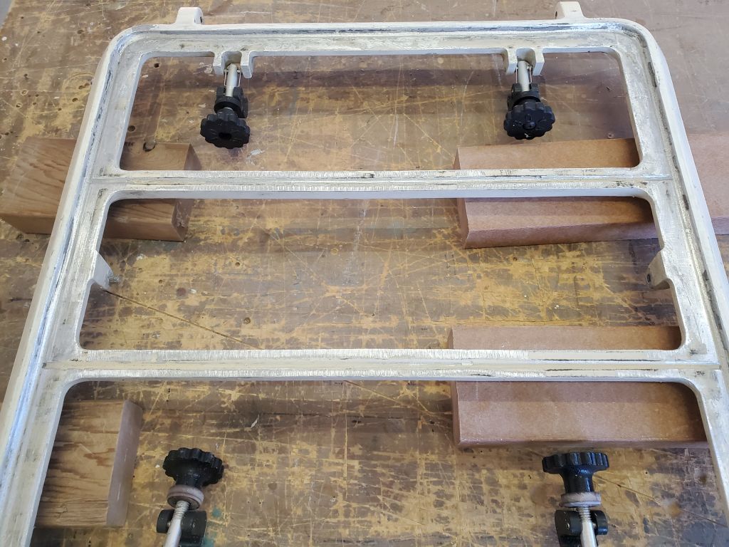
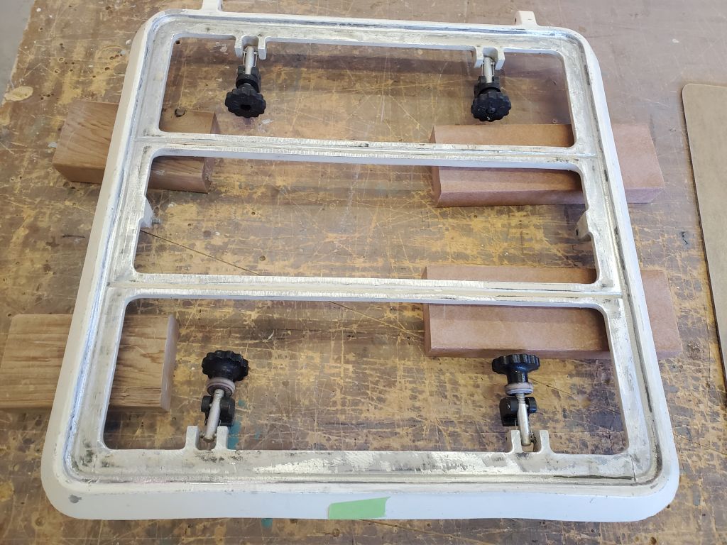
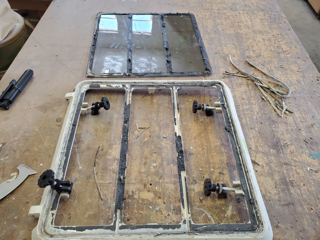
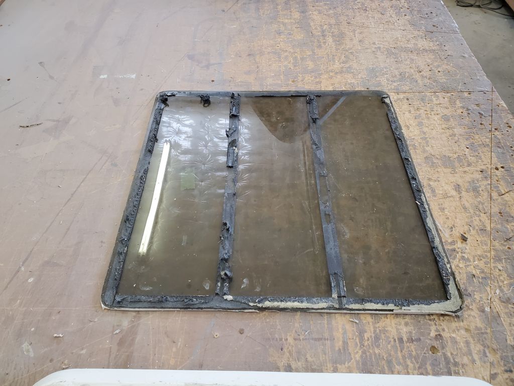
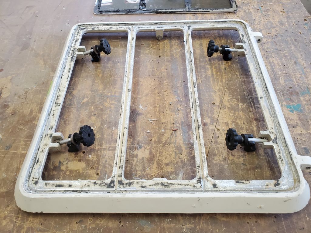
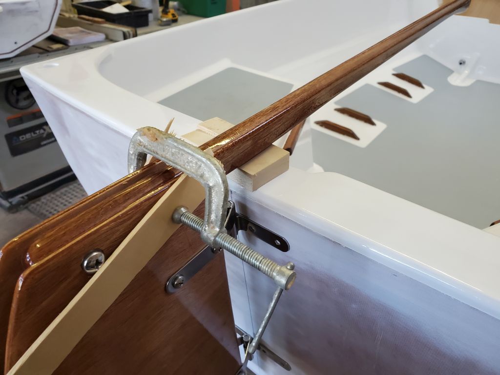
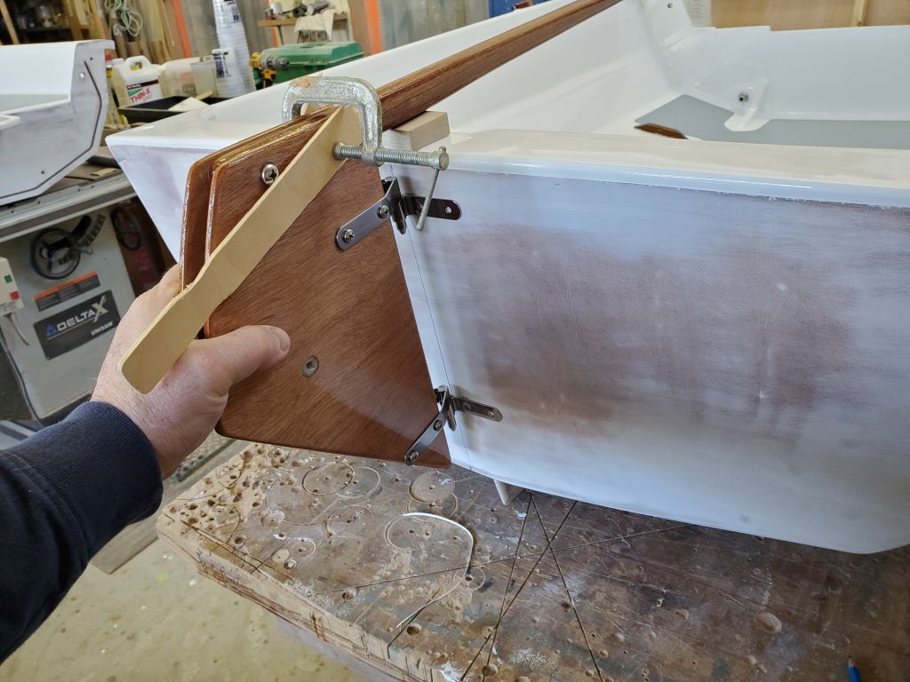
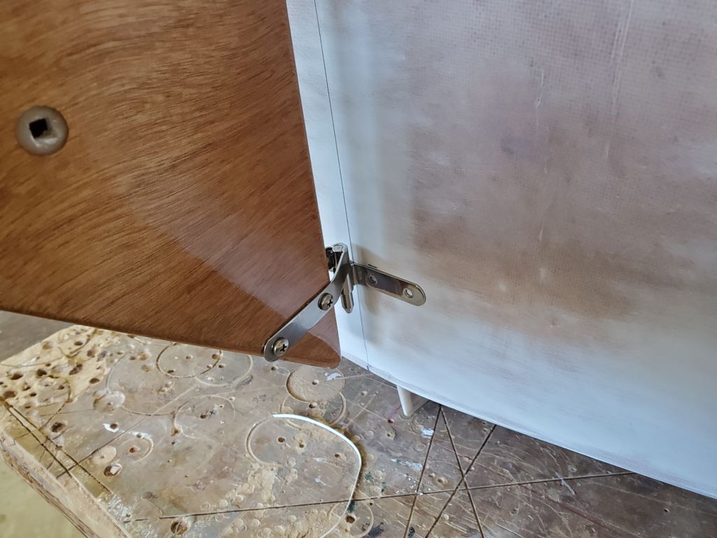
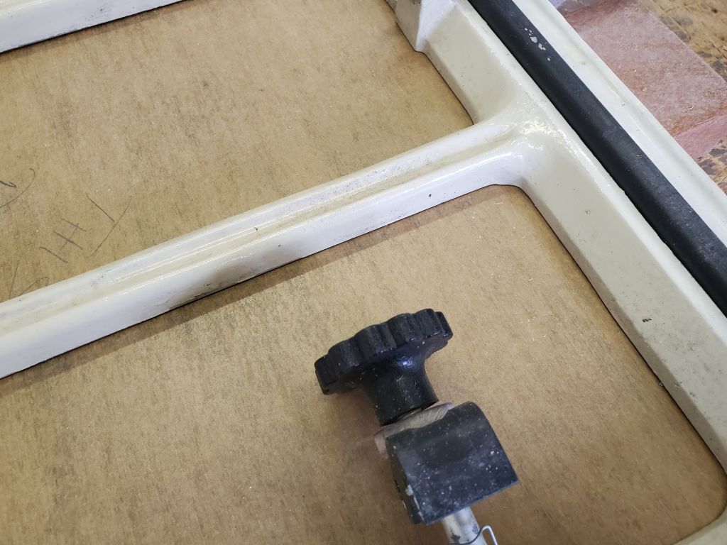
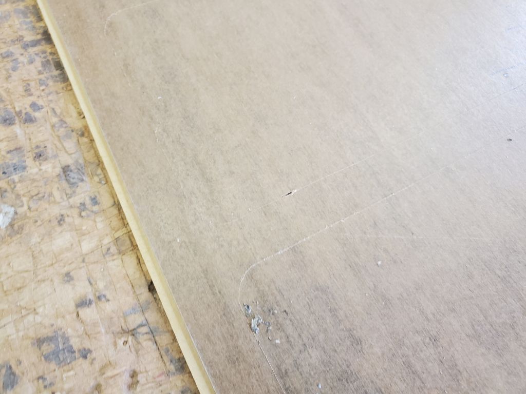
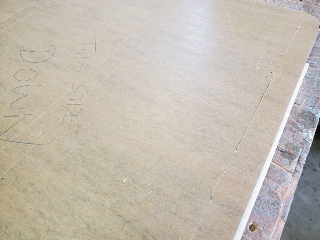
This gave me time to continue work on the hatch lens replacement. The lens was intentionally a bit smaller than the hatch opening, leaving a cosmetic caulking groove around the perimeter, meaning the lens could move about fairly easily in the opening. But I needed to secure it in a reproducible way so that I could flip the hatch and trim the protective paper around the structural members beneath. To register the lens from the top side of the hatch, I came up with an easy method using some paint sticks taped to the paper on the top surface of the lens; this simply held the lens from sliding in any direction, which meant that once I’d trimmed the paper, I could easily place the lens in the opening and know that the prepared surfaces would properly mate.
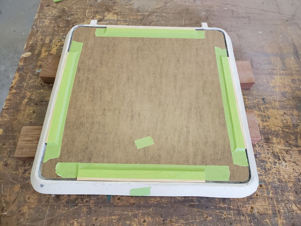
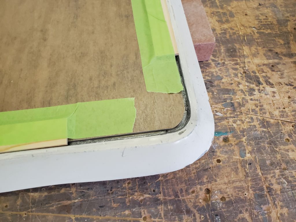
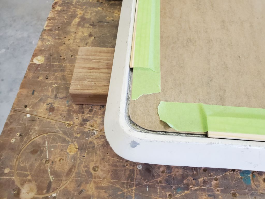
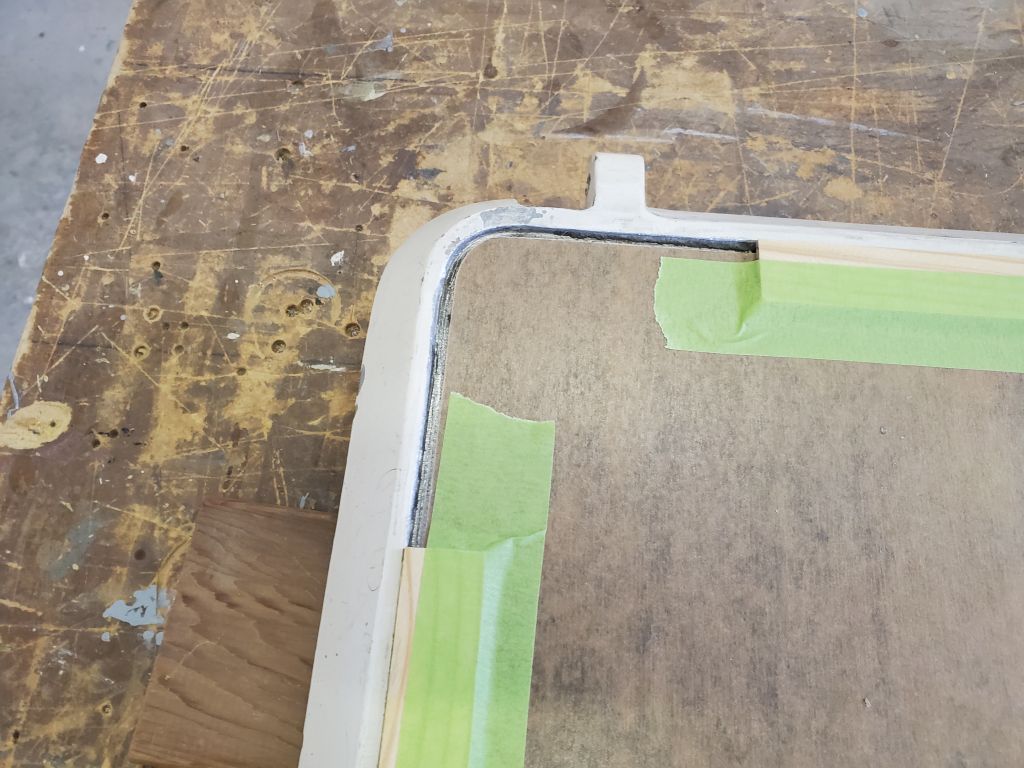
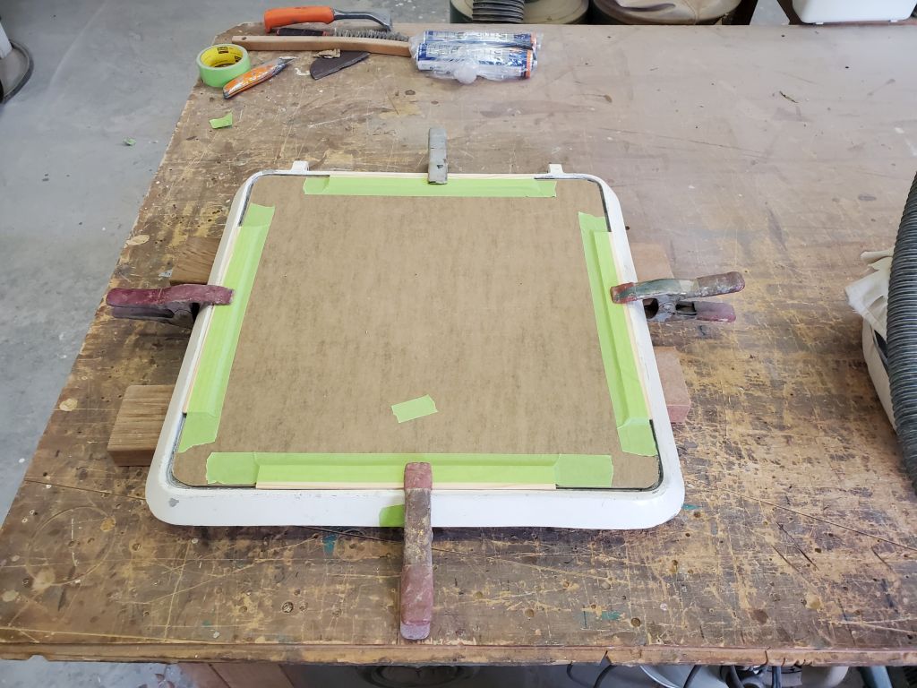
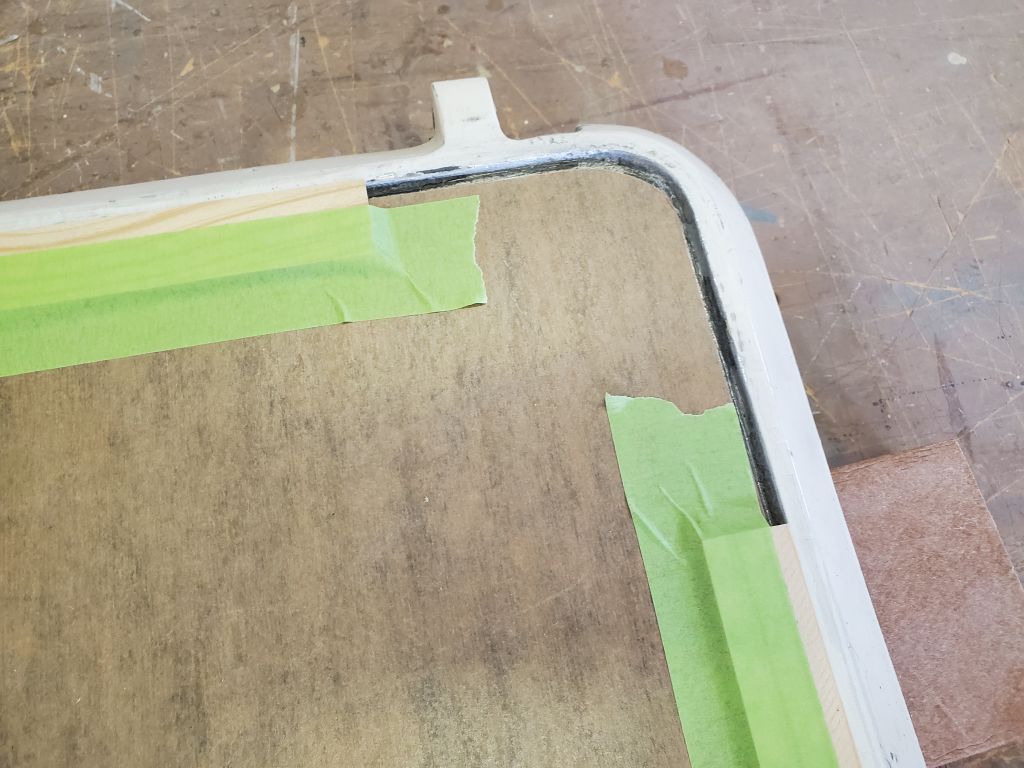
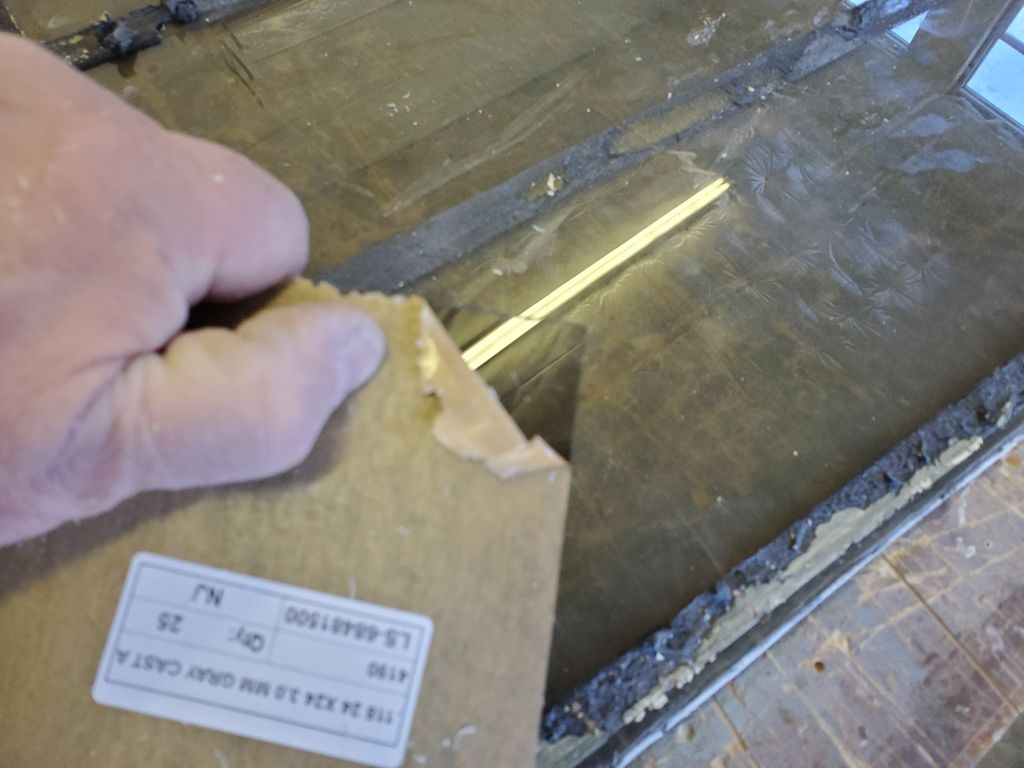
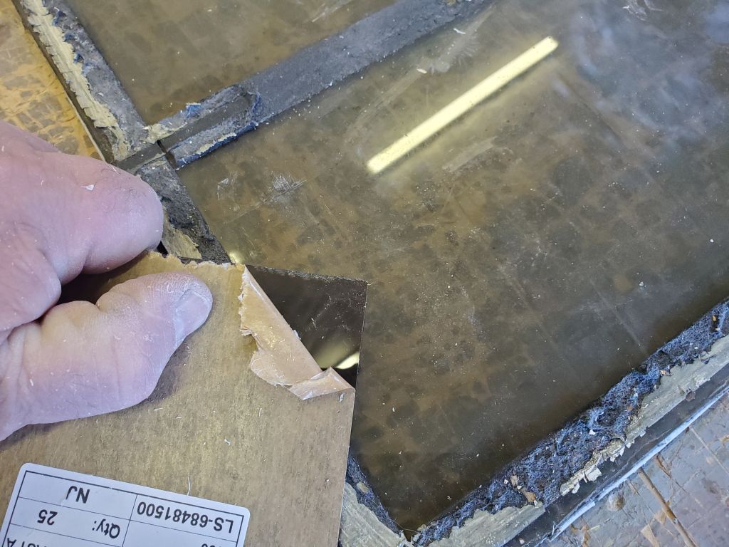
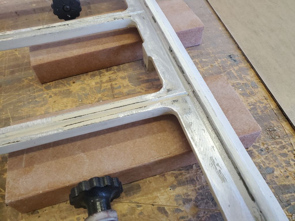
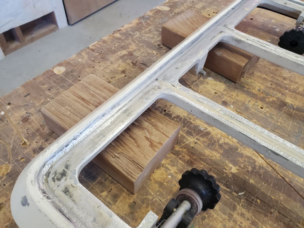
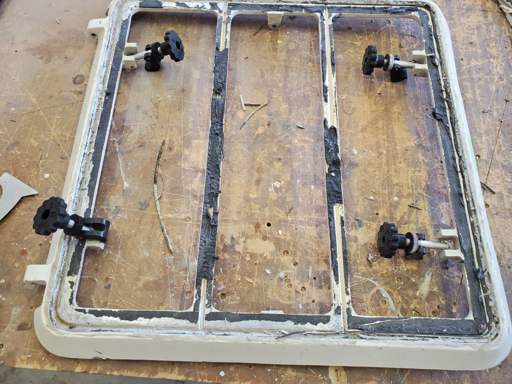
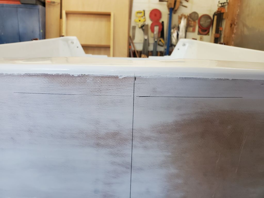
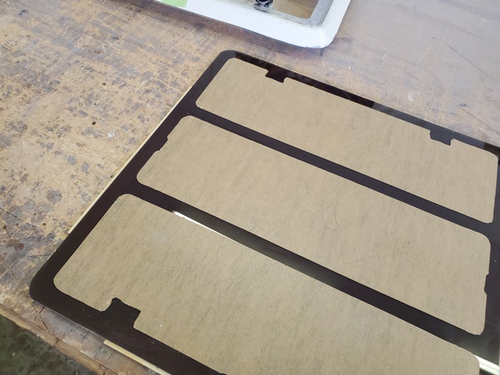
I clamped the lens lightly in place, then turned the hatch over so I could use a sharp knife to carefully score the paper around all the inside edges of the aluminum hatch frame, after which I removed the paper from these bonding areas.
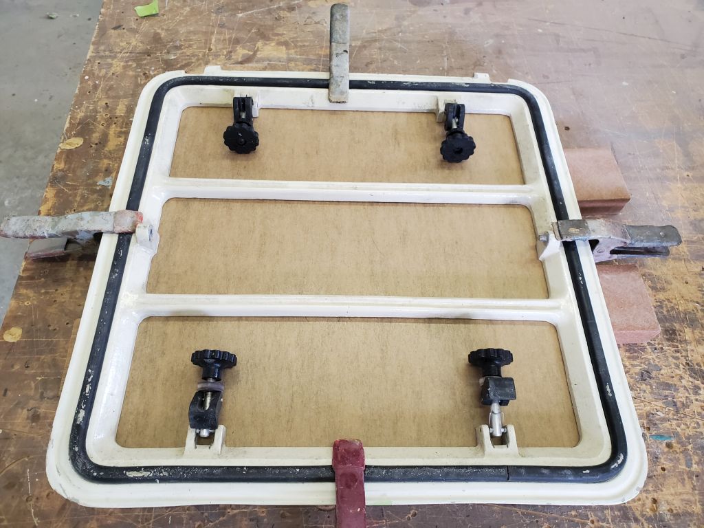
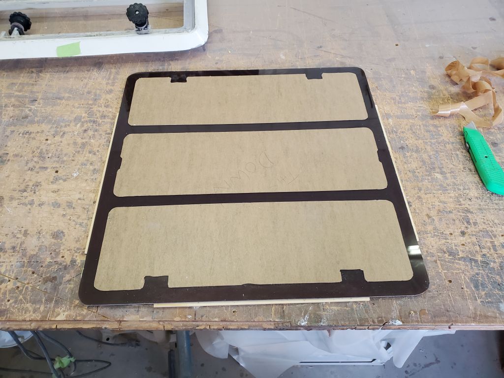
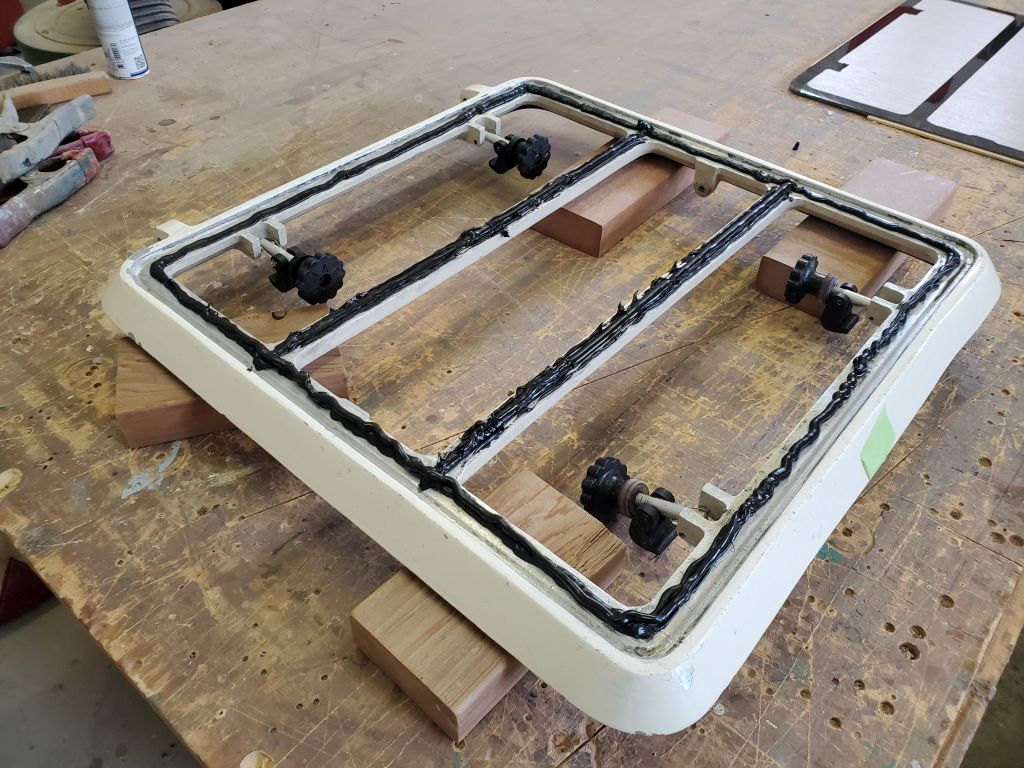
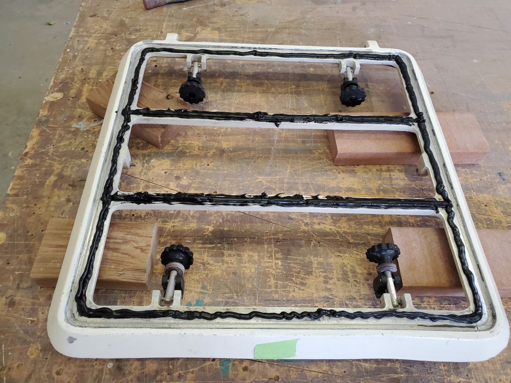
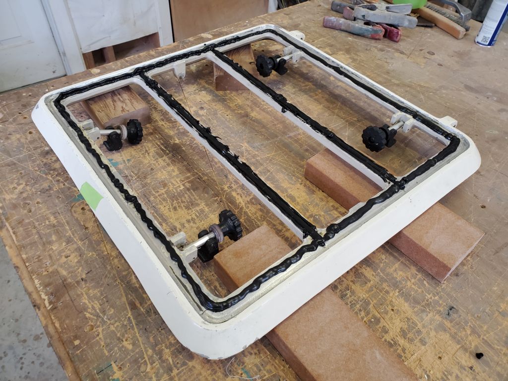
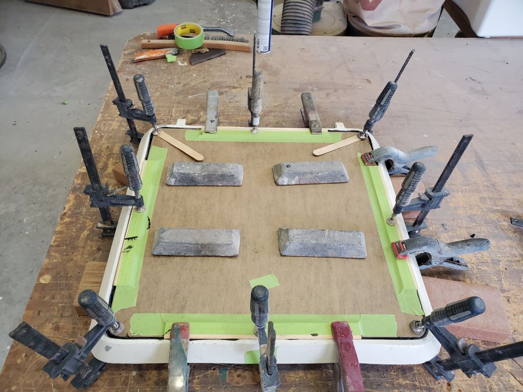
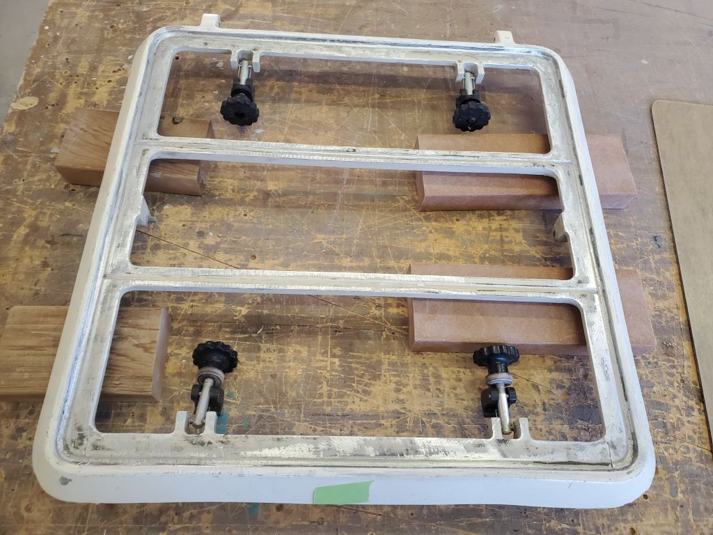
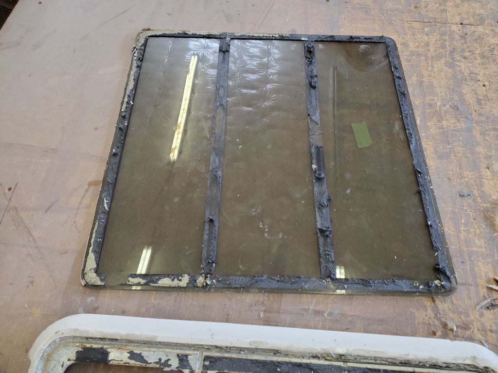
After a final cleanup of the prepared hatch frame, I secured the lens in place with heavy beads of Sikaflex 295UV, and clamped and weighted the lens into the fresh sealant. I did not try to fill and tool the cosmetic seam around the outside of the lens now, as it was impossible to clamp the lens and still access the outer seam; that would happen later, after the initial sealant application cured. All the sealing and bonding of the lens occurred with the initial sealant application, and the outer edge was largely a cosmetic concern. Although I couldn’t get the camera beneath the hatch the way it was supported on the table, I did peer beneath by eye to confirm good contact of the lens and squeezeout of sealant all around the inside. I left the assembly to cure.