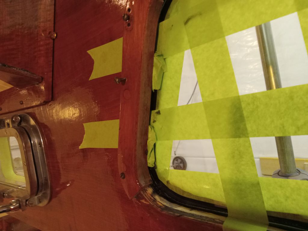
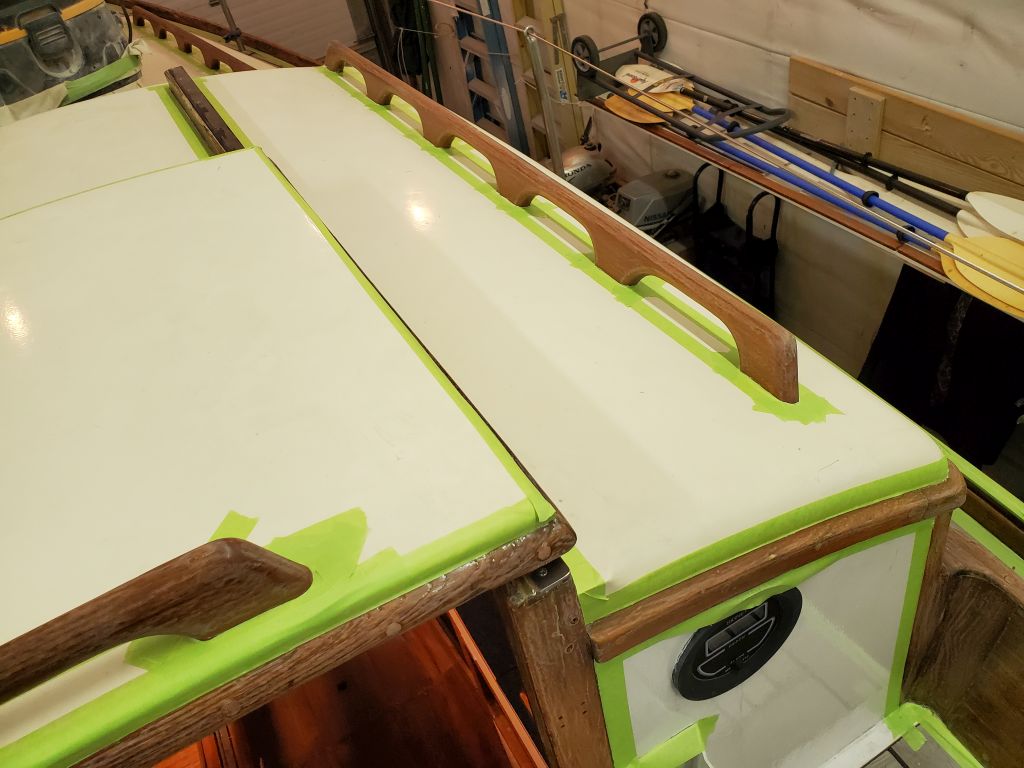
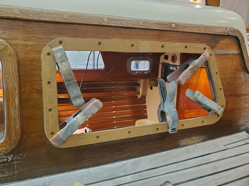
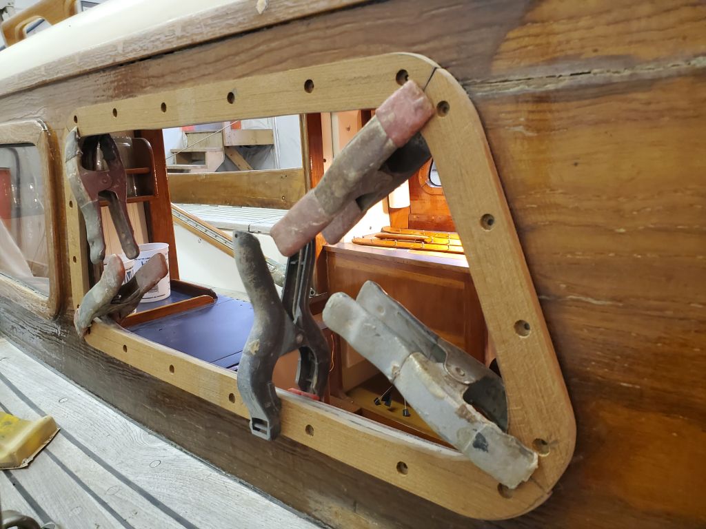
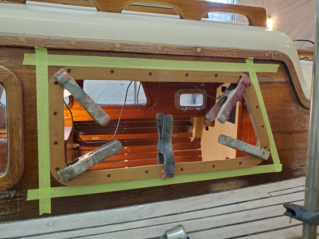
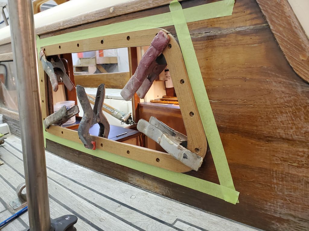
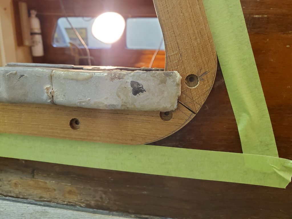
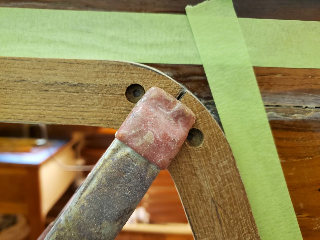
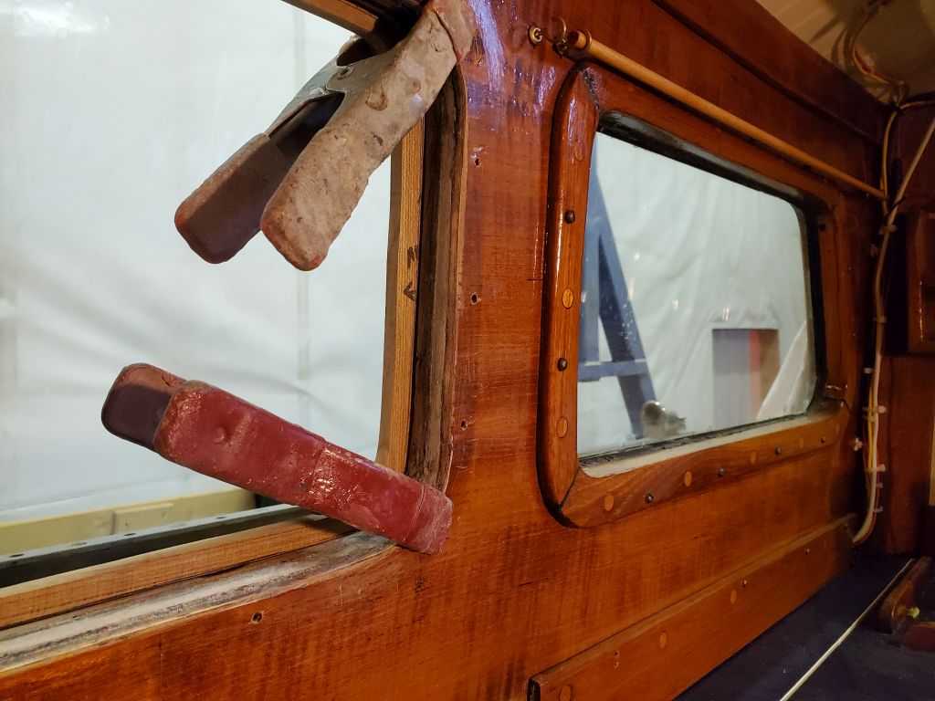
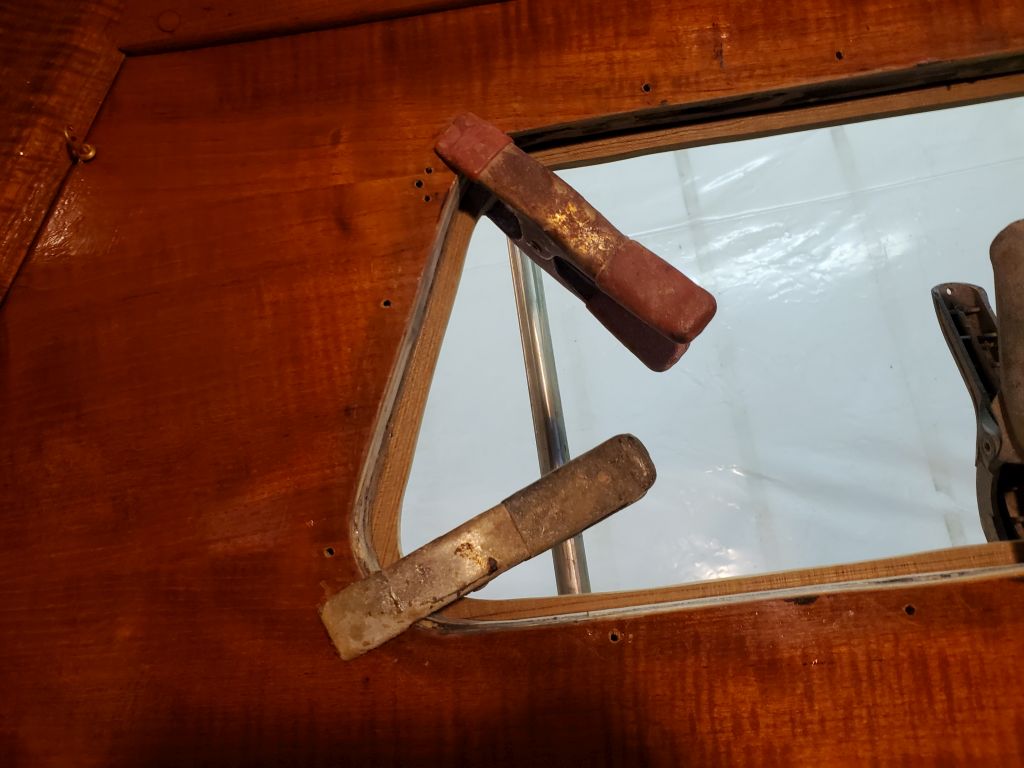
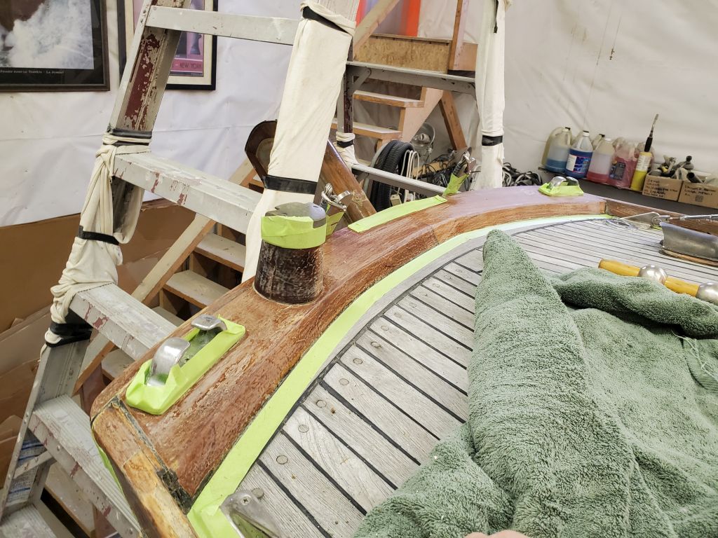
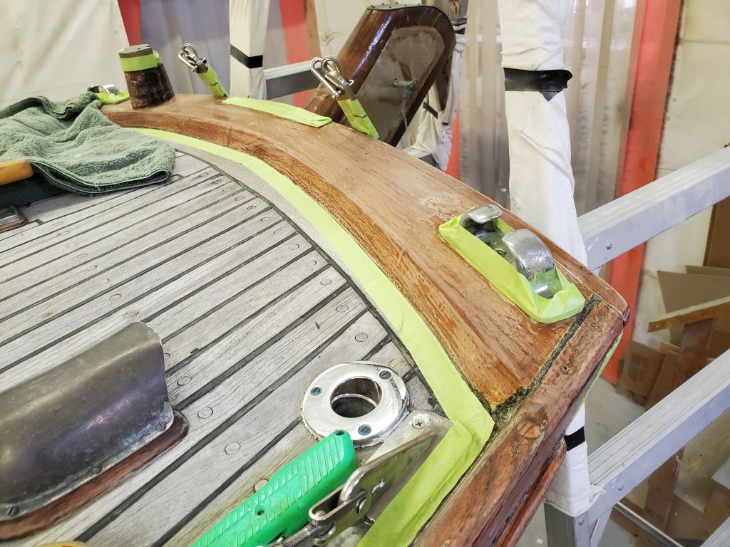
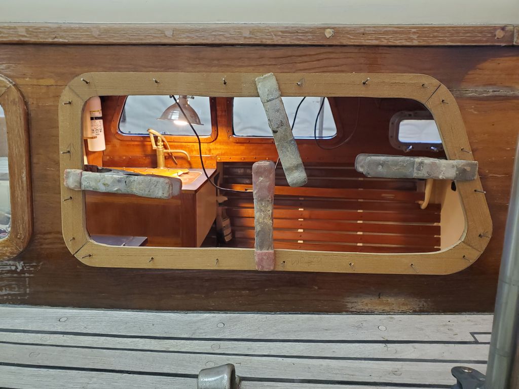
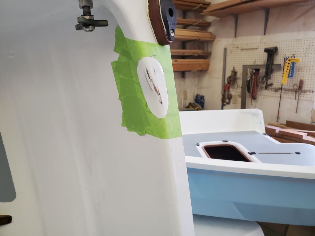
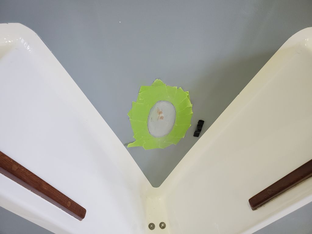
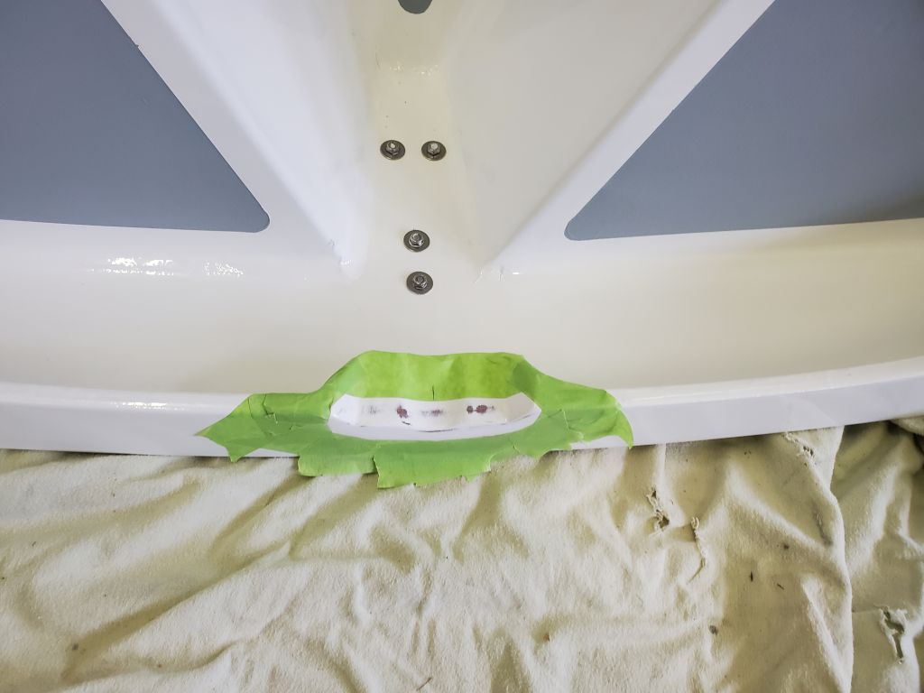
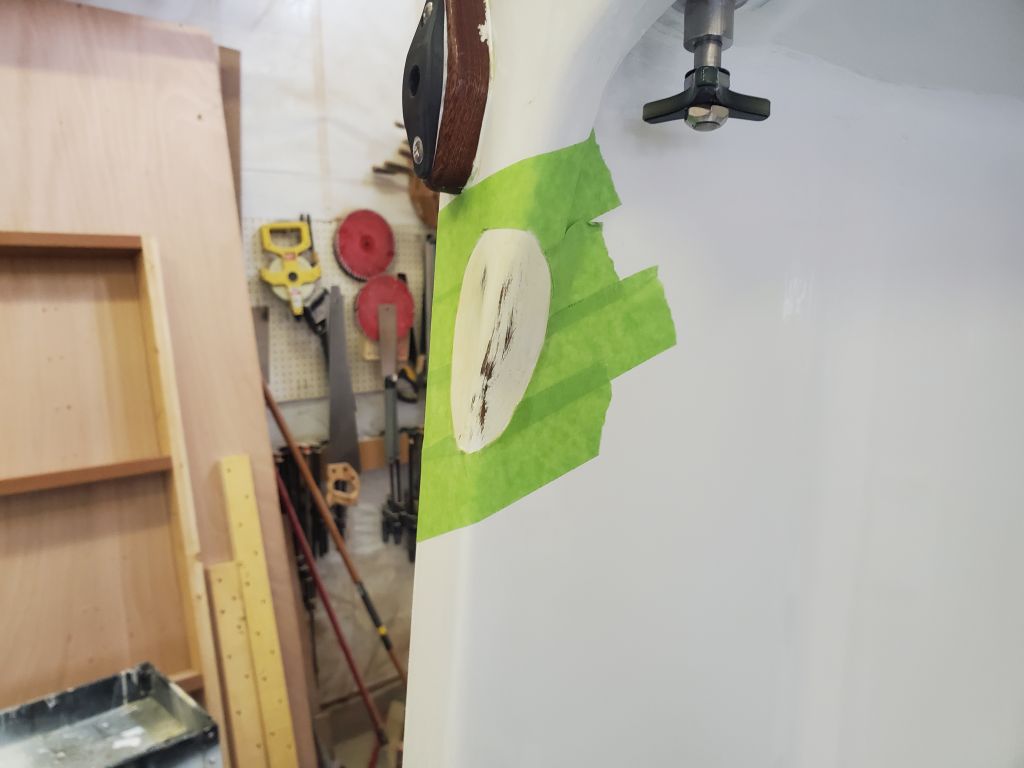
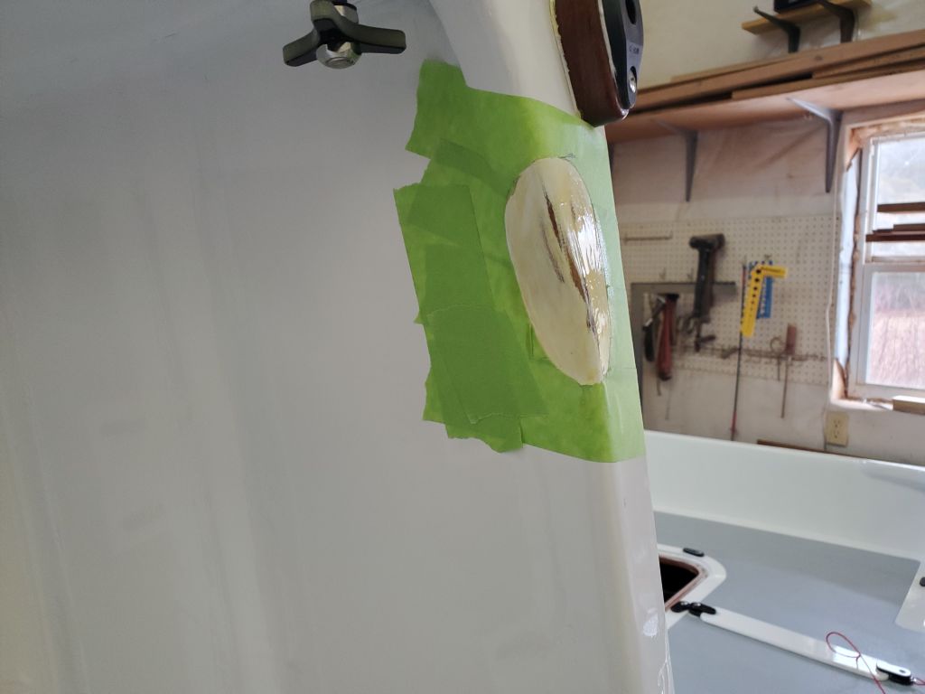
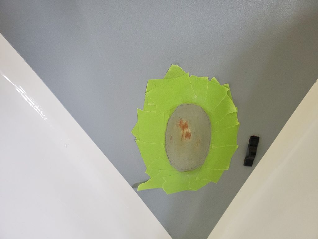
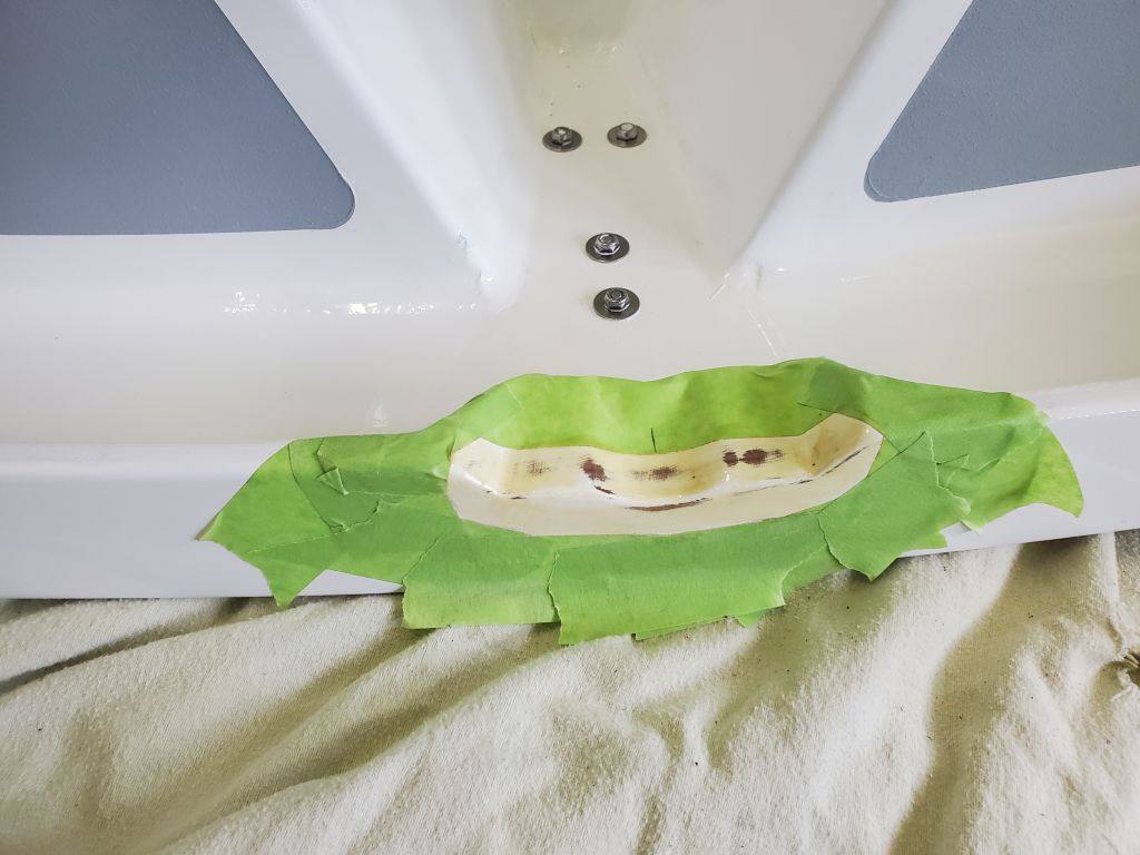
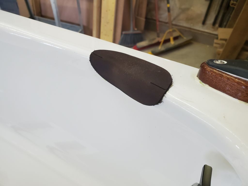
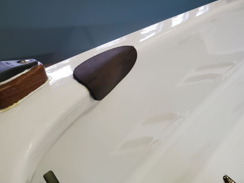
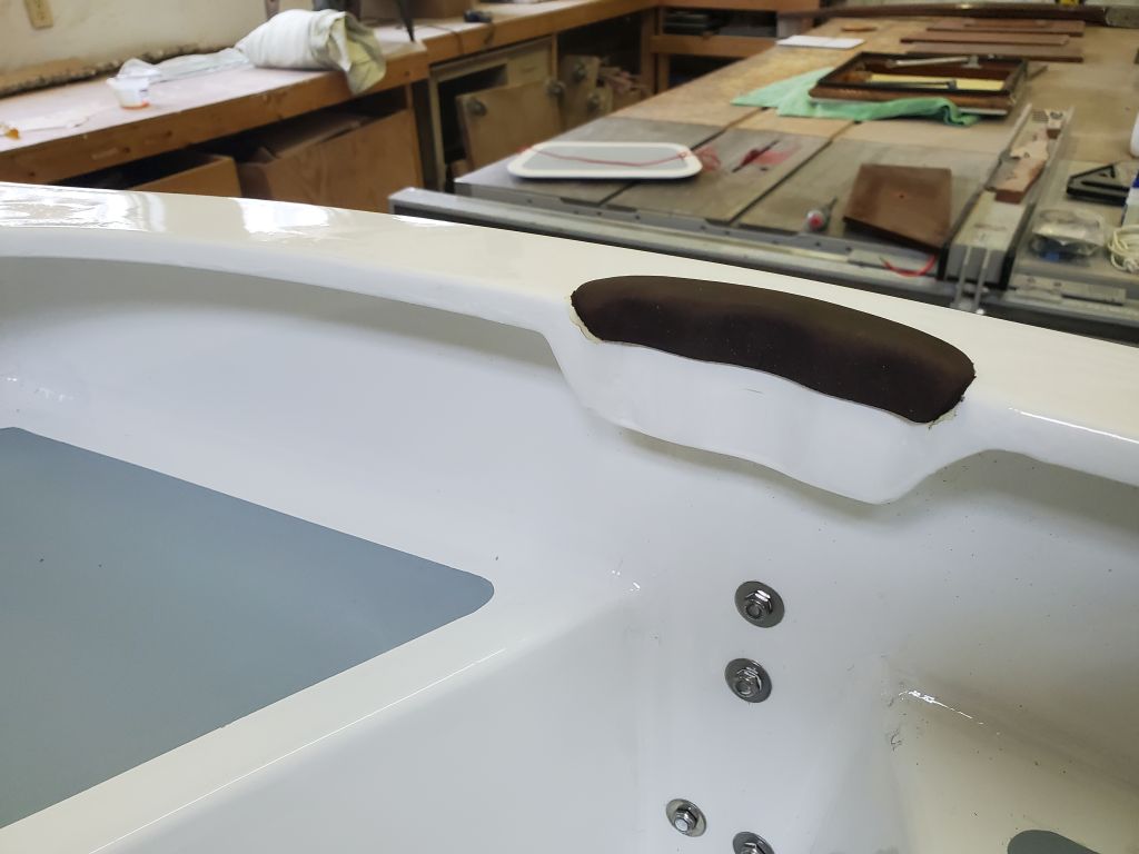
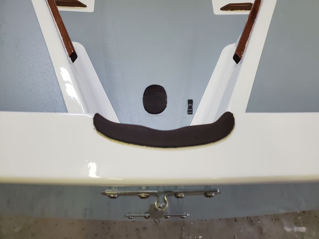
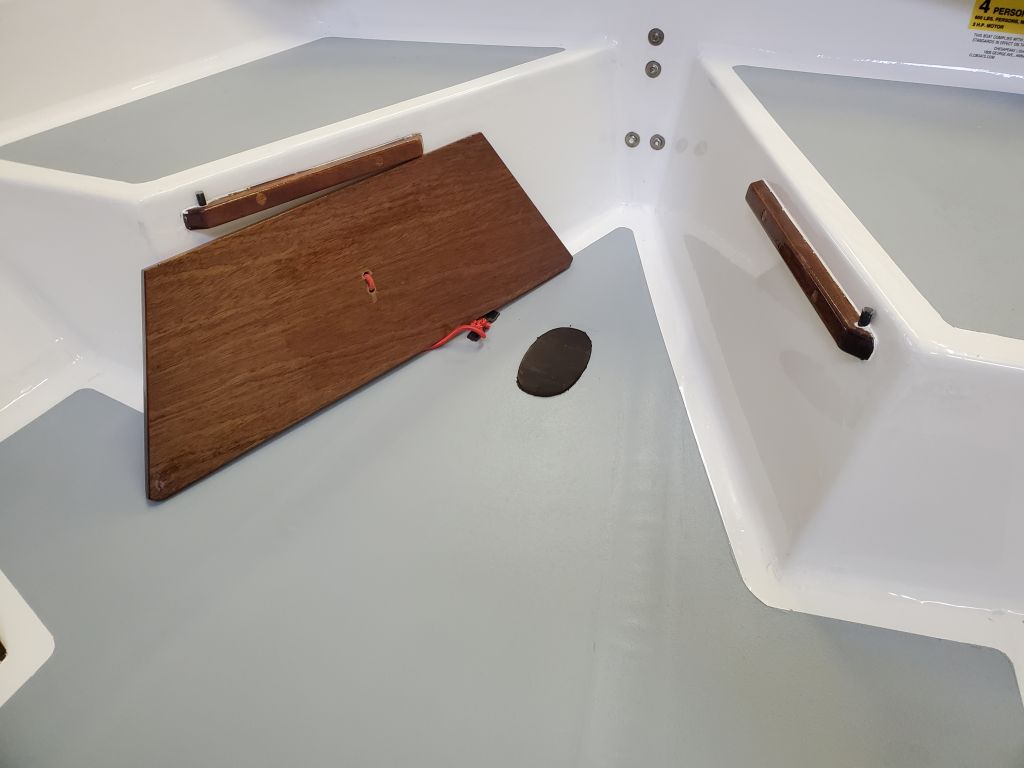
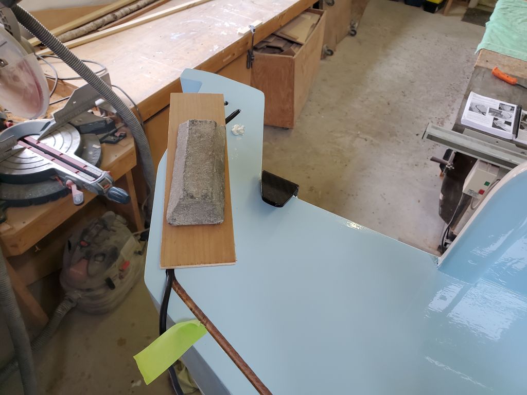
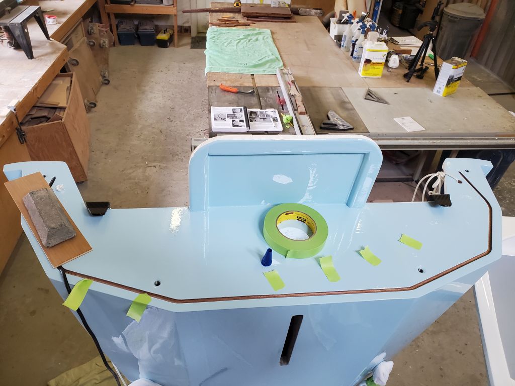
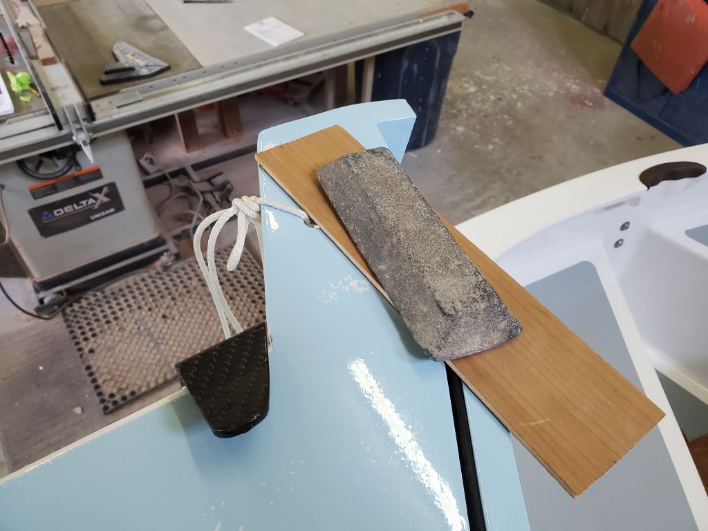
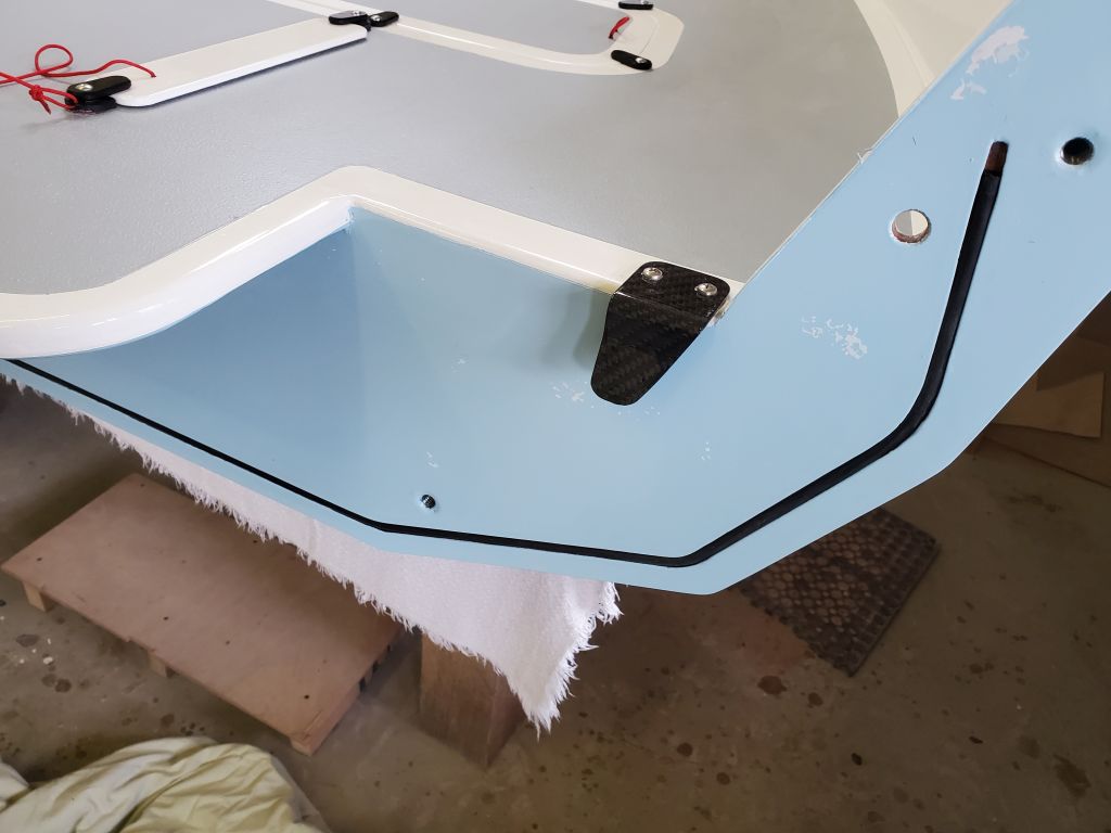
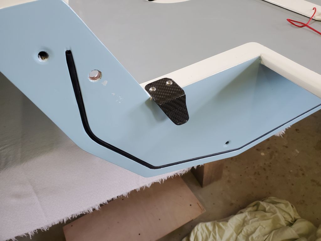
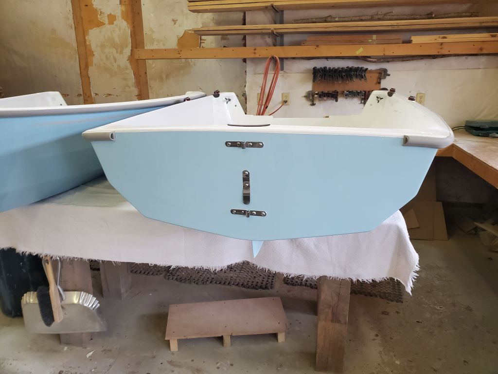
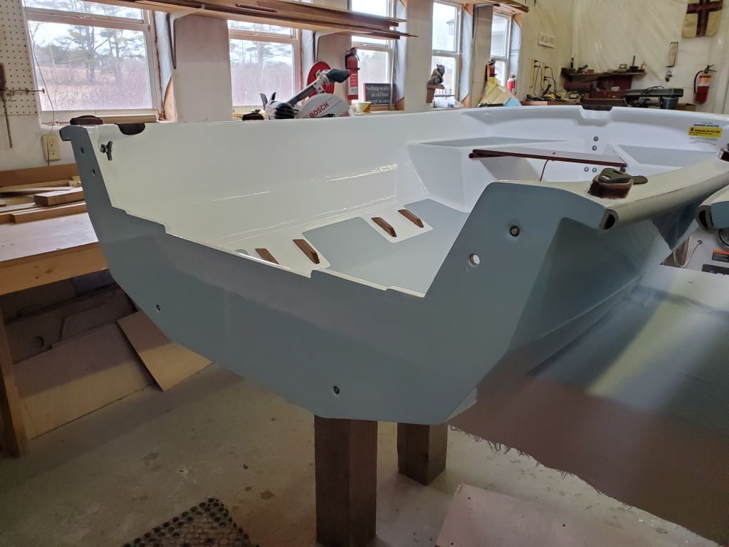
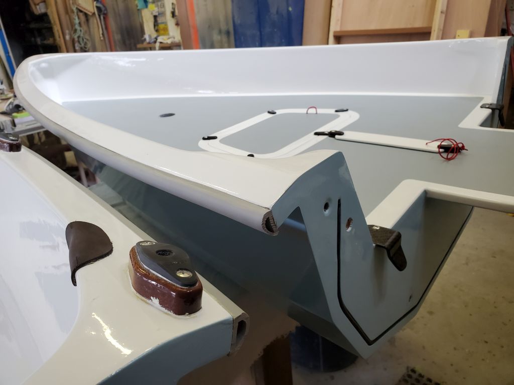
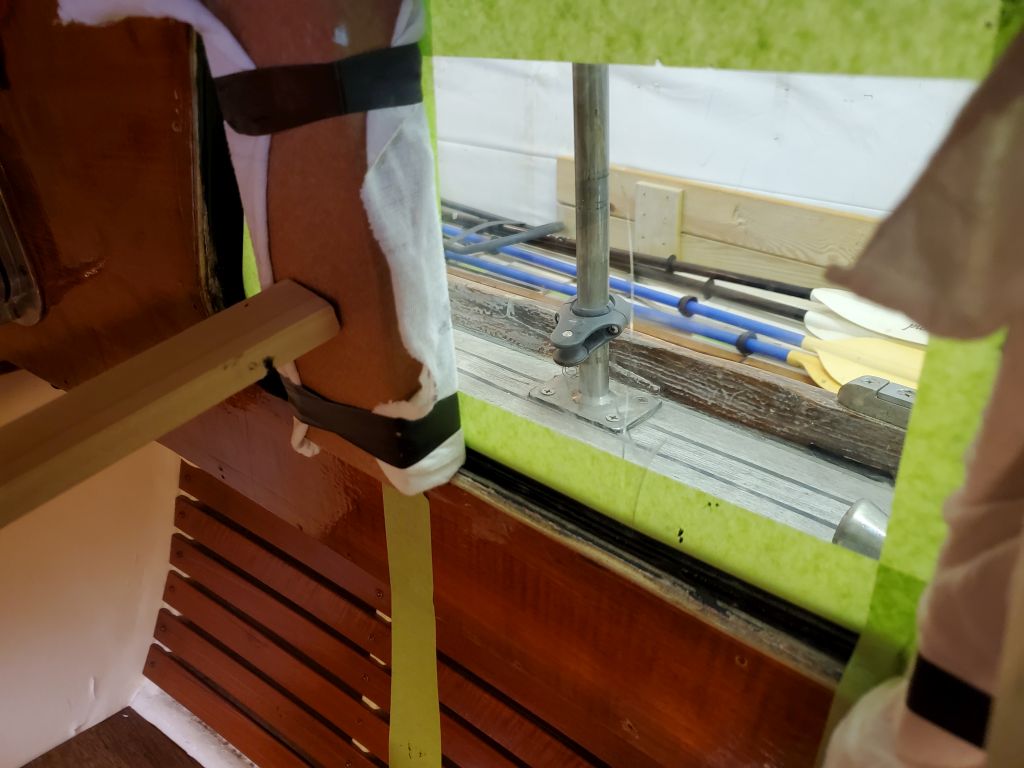
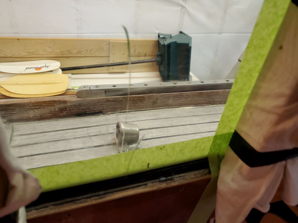
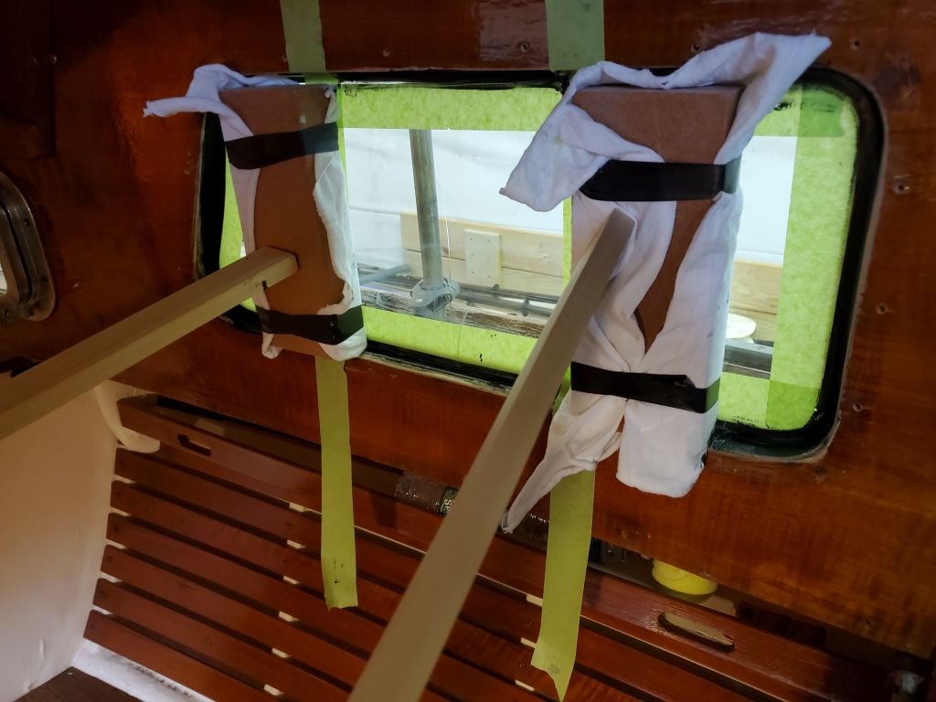
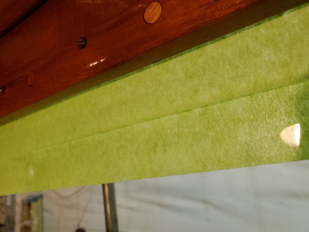
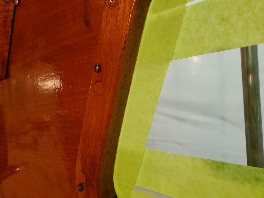
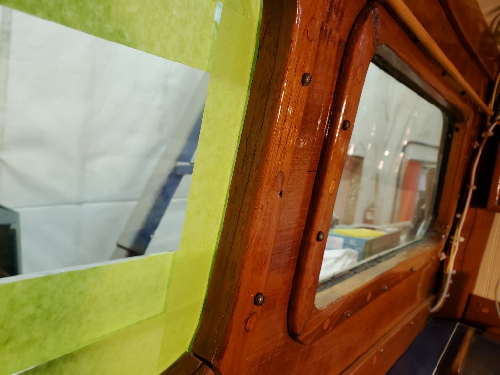
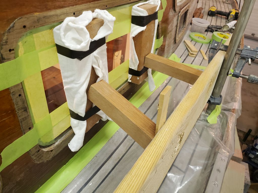
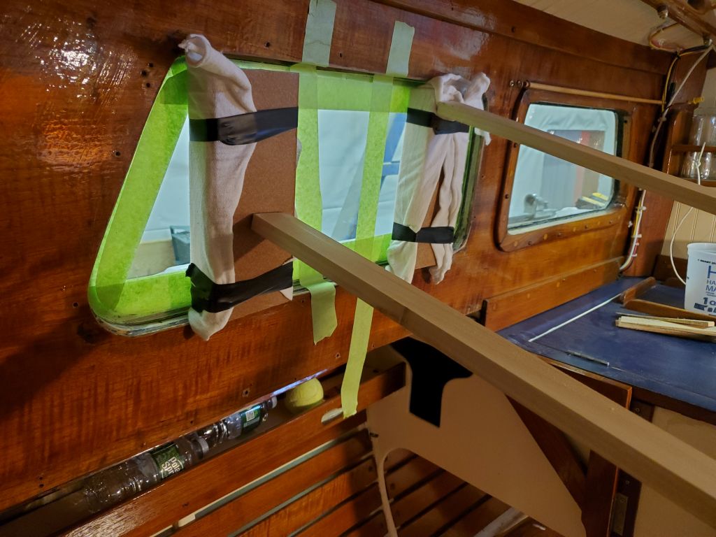
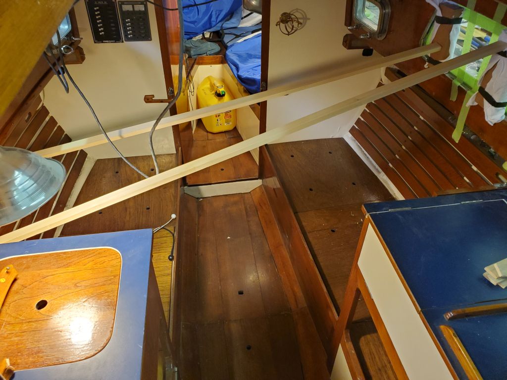
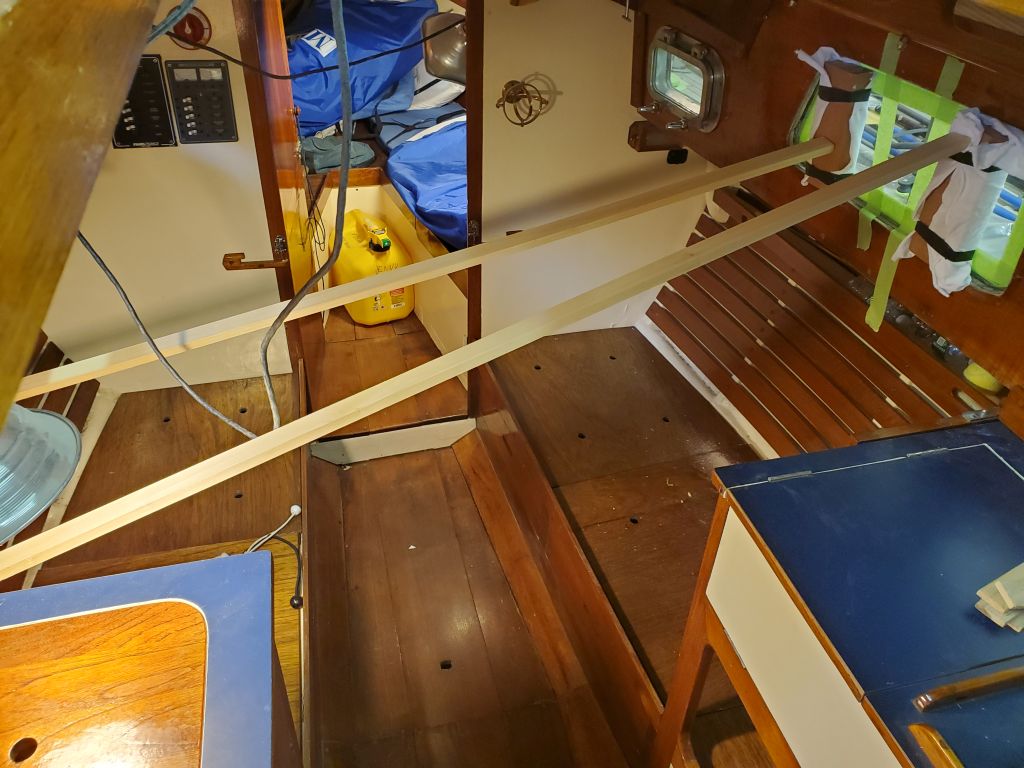
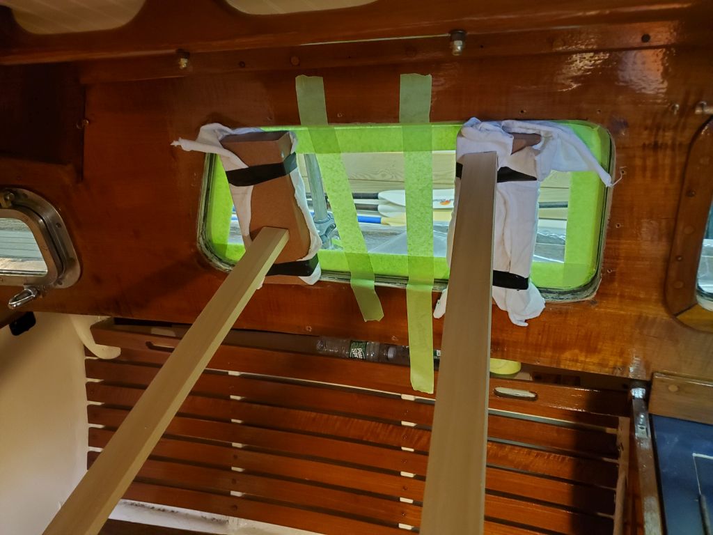
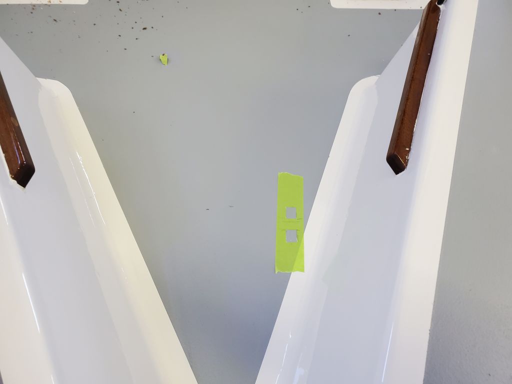
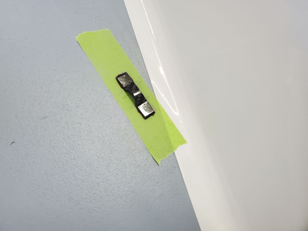
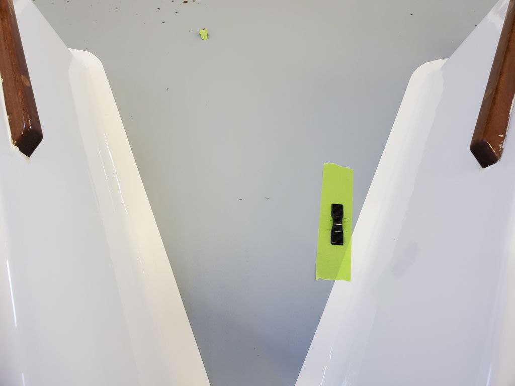
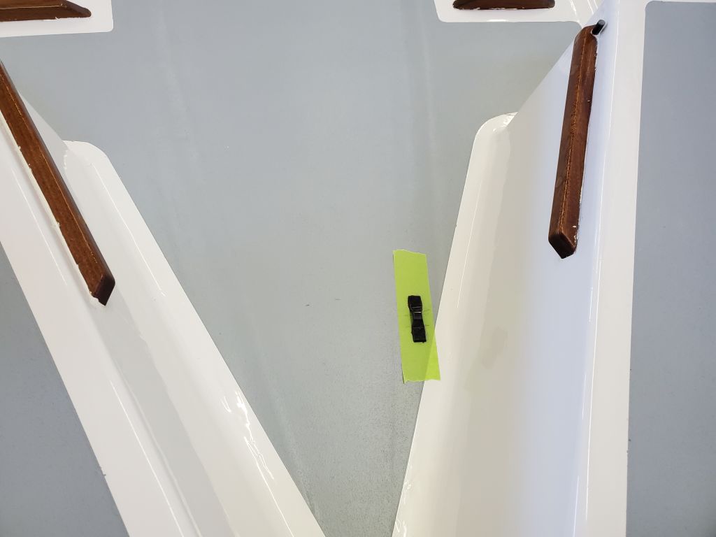
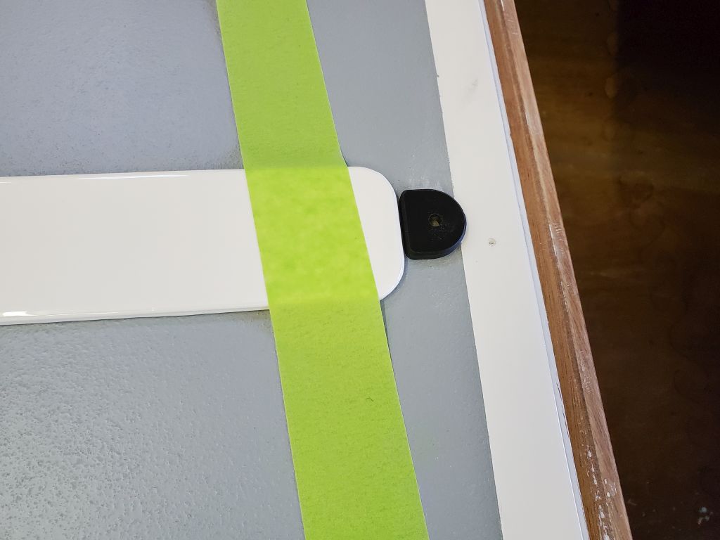
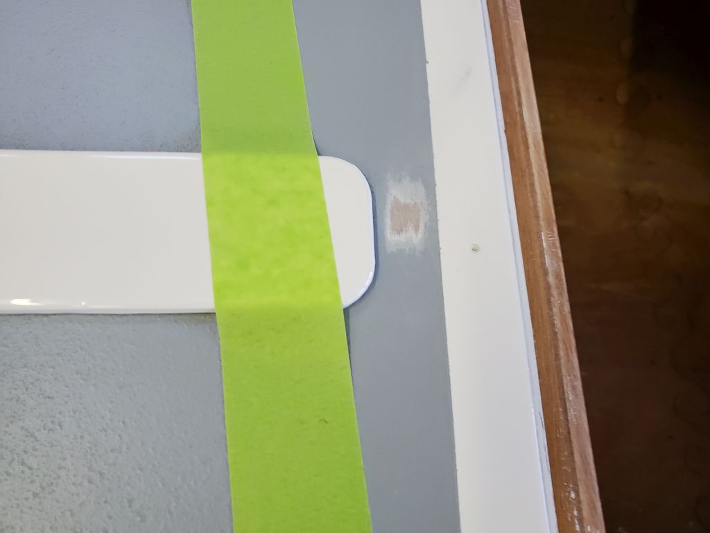
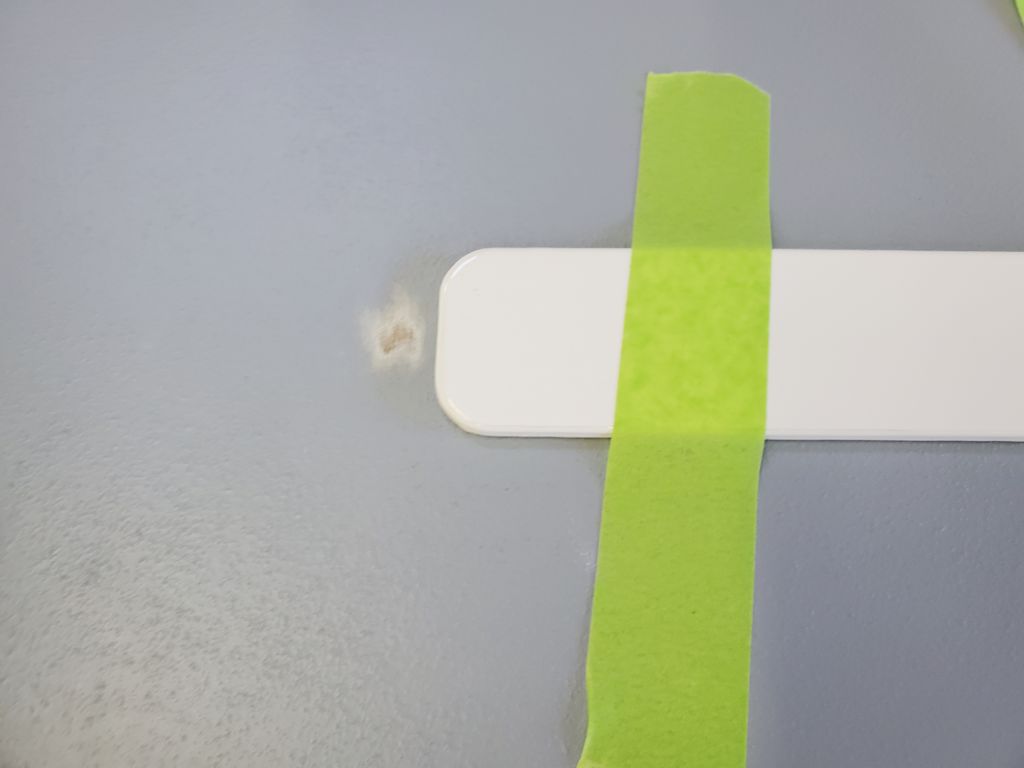
To help protect a few key contact points when nesting the forward hull inside the aft hull, the kit included four leather pads, which needed to be installed in specific locations. I prepared the four locations as directed, and masked off around them to protect adjacent areas while gluing in the leather. There was one patch on the inwale, at the centerline notch; one on the bottom of the dinghy roughly a foot forward of the transom; and one on each side at the forward end of the gunwales, where the bulkhead gussets were. To gain the best access to the two patches at the aft end, I stood the hull on its transom next to the bench. This also allowed working on the two patches near the upper end of the gunwales.
Once I’d masked off the perimeter of the patches, I sanded off the glossy paint and nonskid as needed, and cleaned the surface.
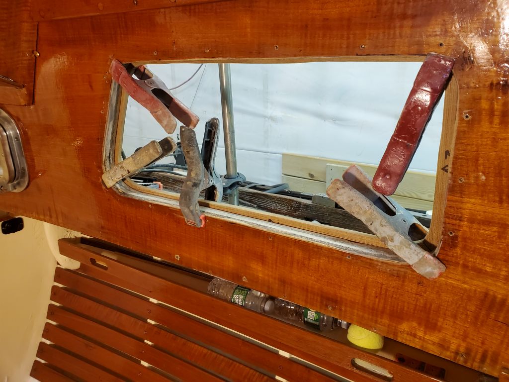
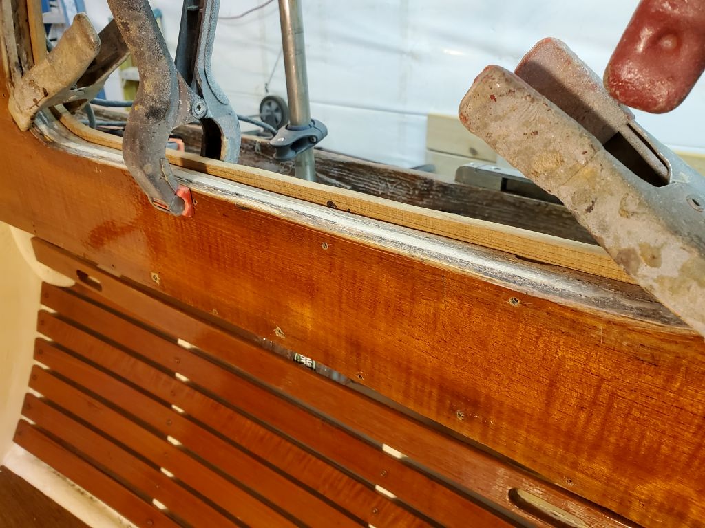
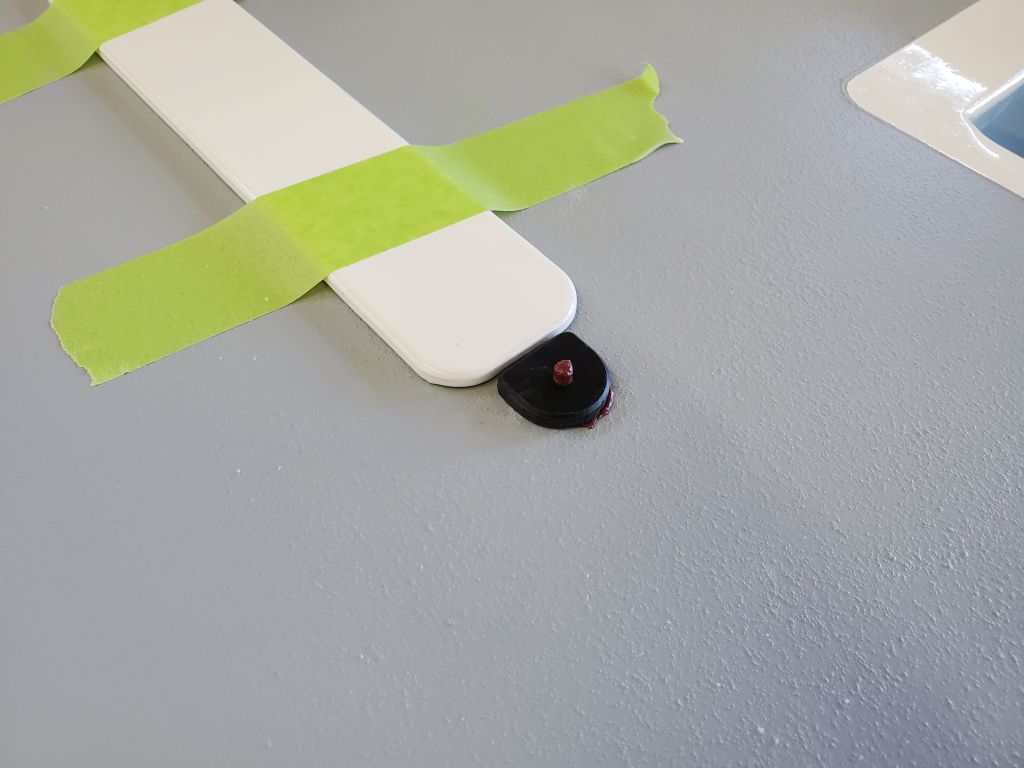
The leather was all cut to size and scored with alignment marks on their centerlines to help with positioning. To install them, I applied two coats of contact cement (the real stuff) to all the bonding areas and the back side of the leather patches, letting each coat dry in the usual way. Then I installed the leather in its designated areas, which frankly went more smoothly than I’d been expecting. I used a small roller to press the leather down securely in all areas.
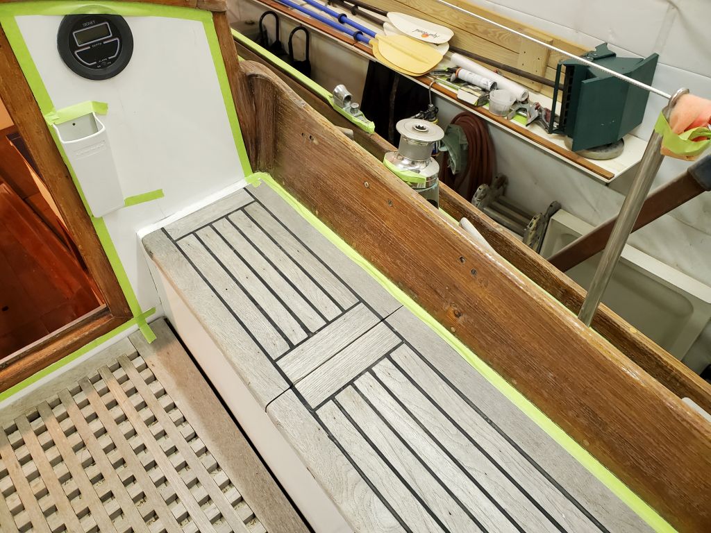
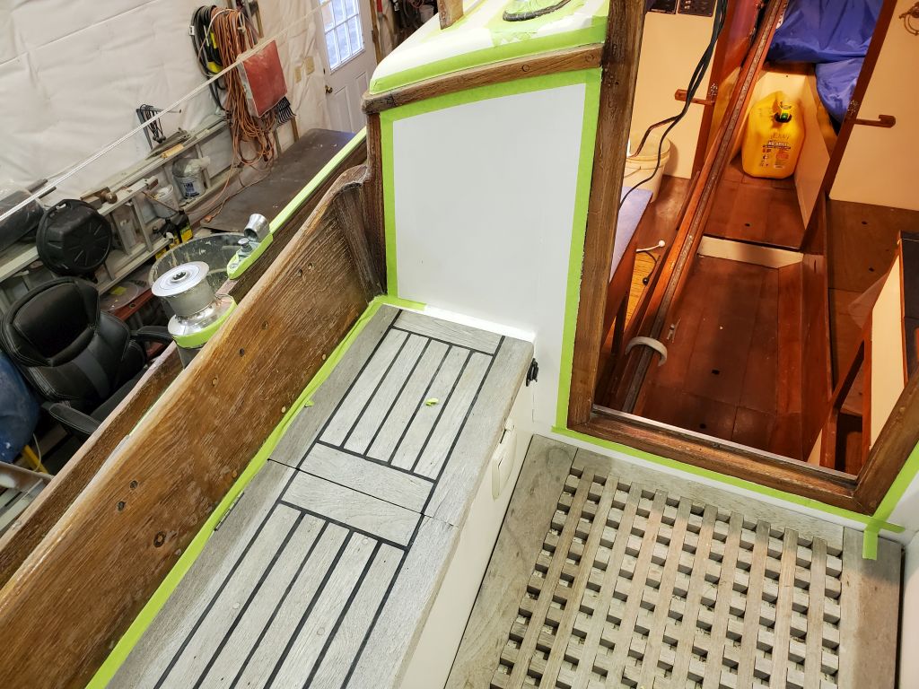
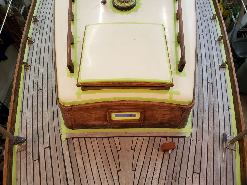
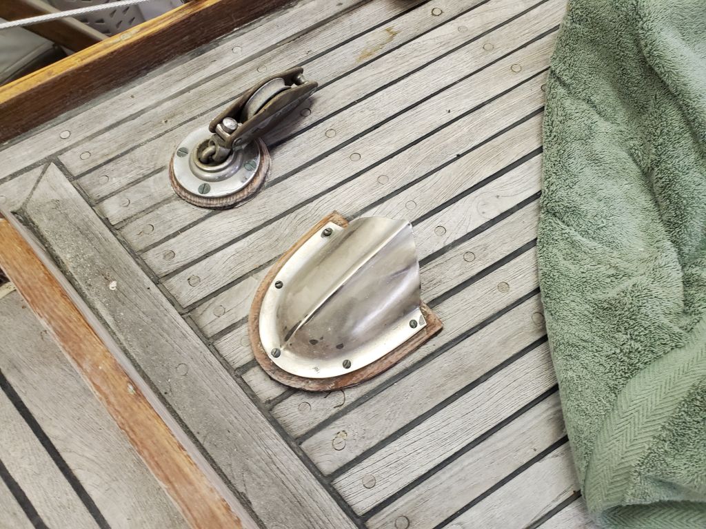
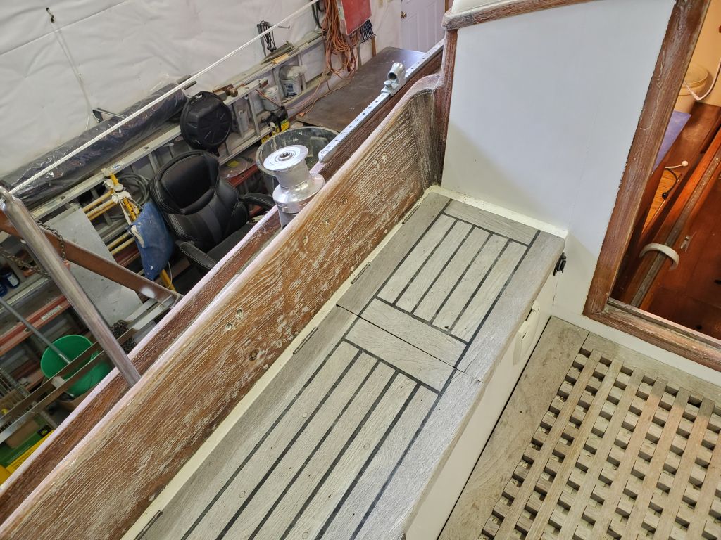
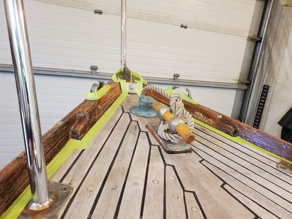
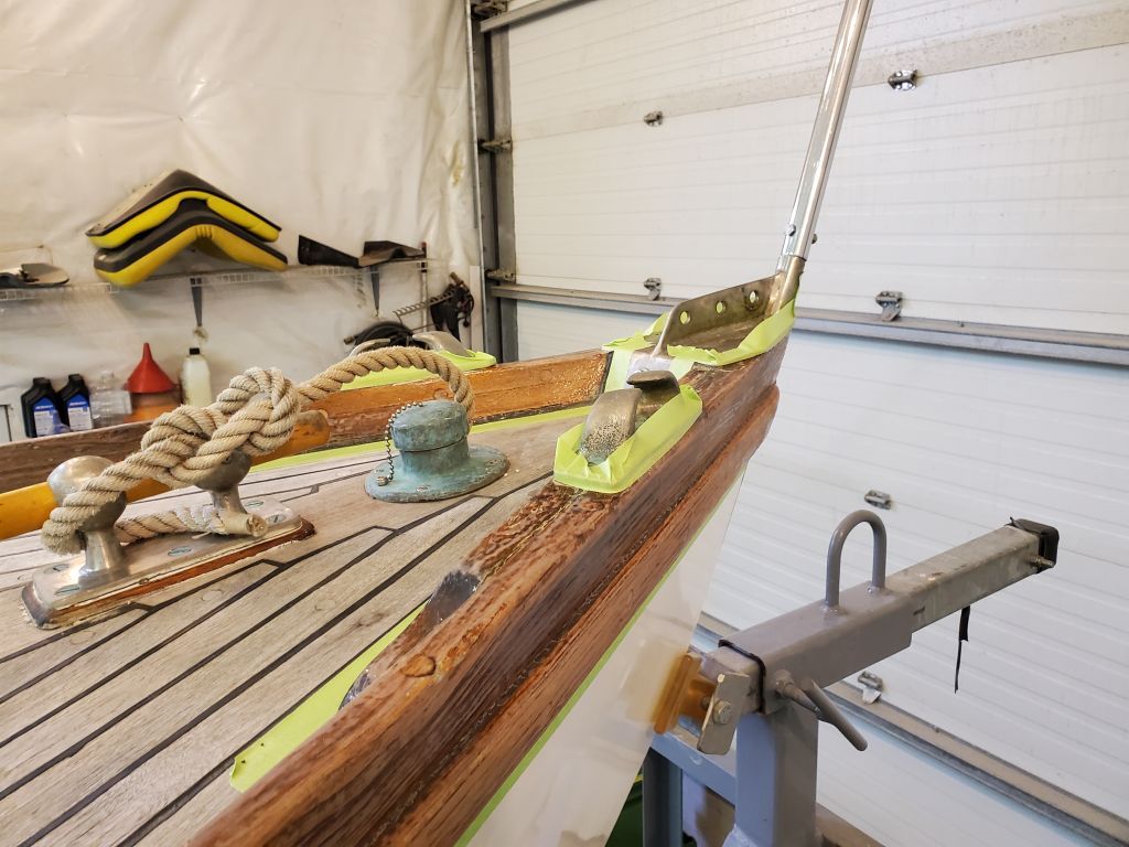
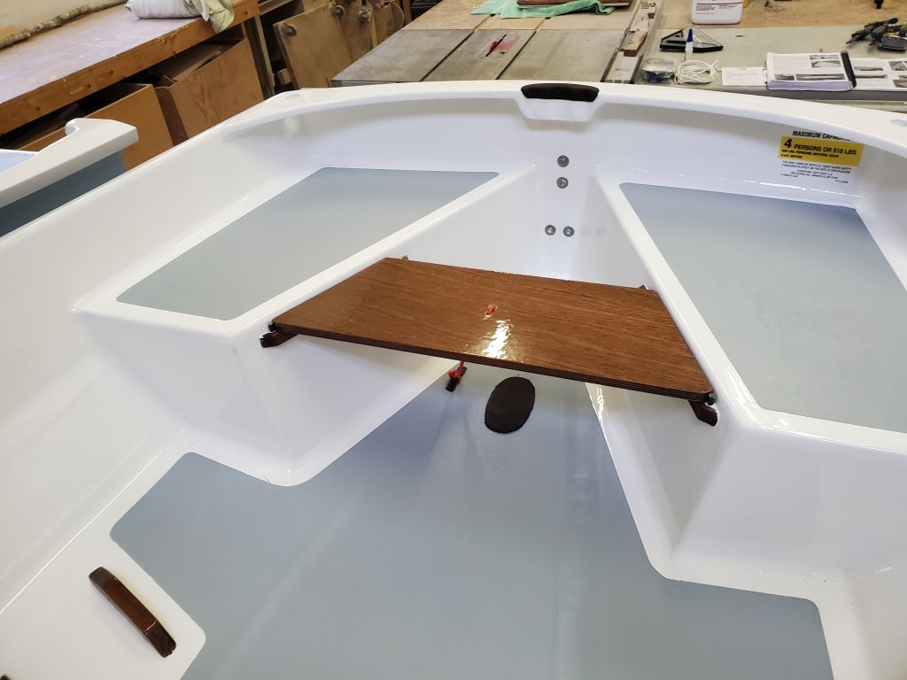
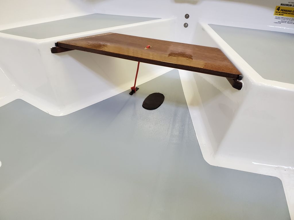
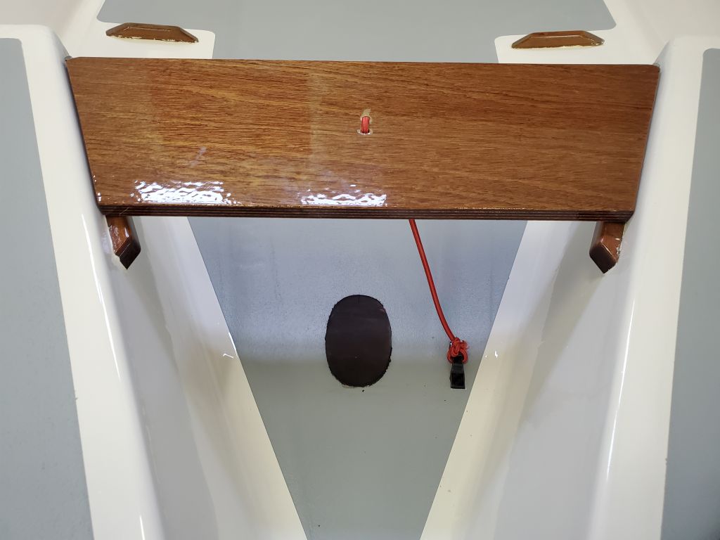
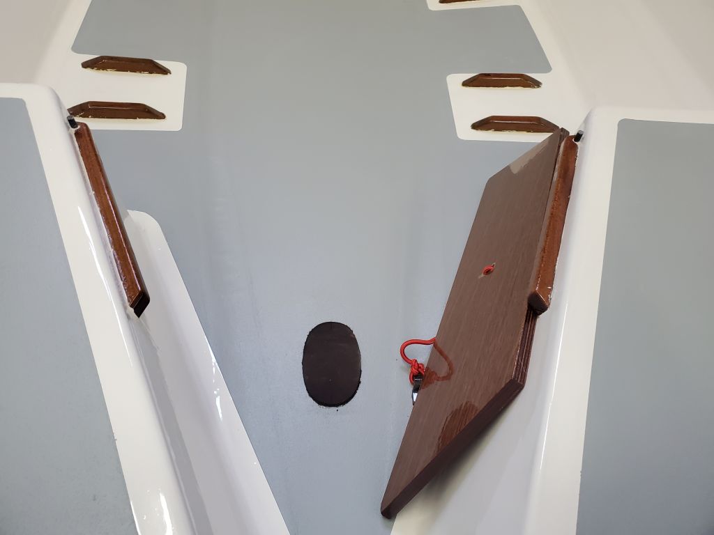
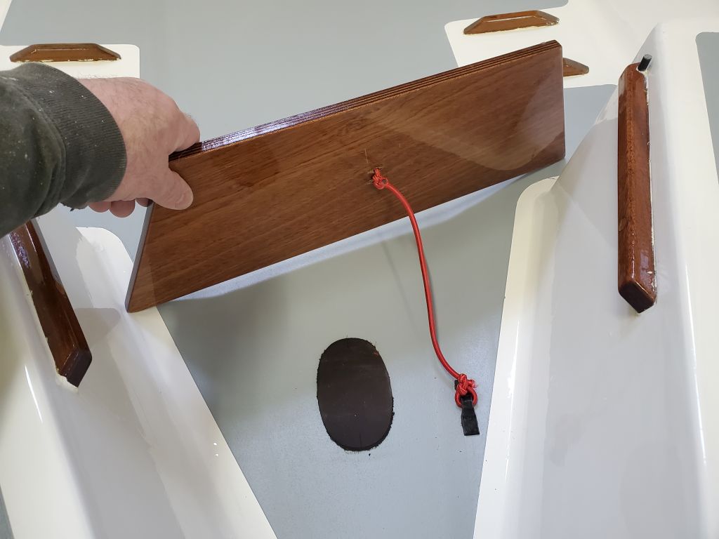
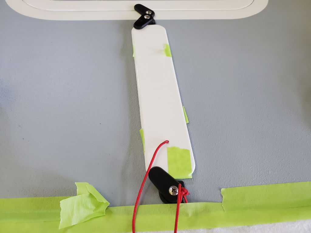
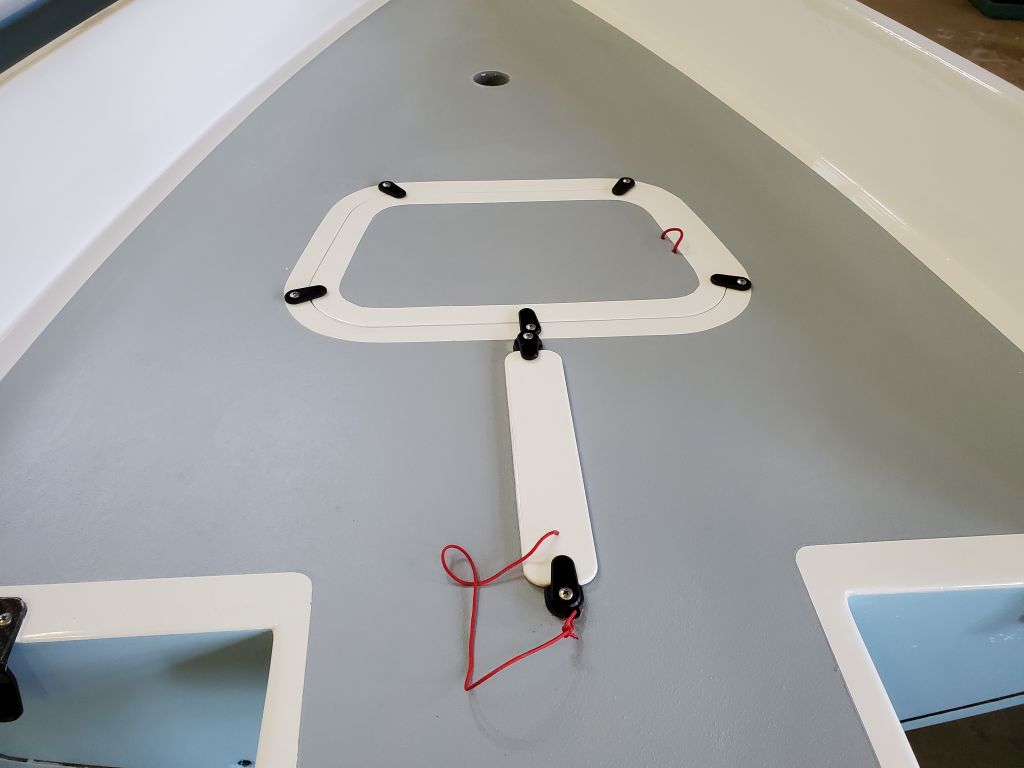
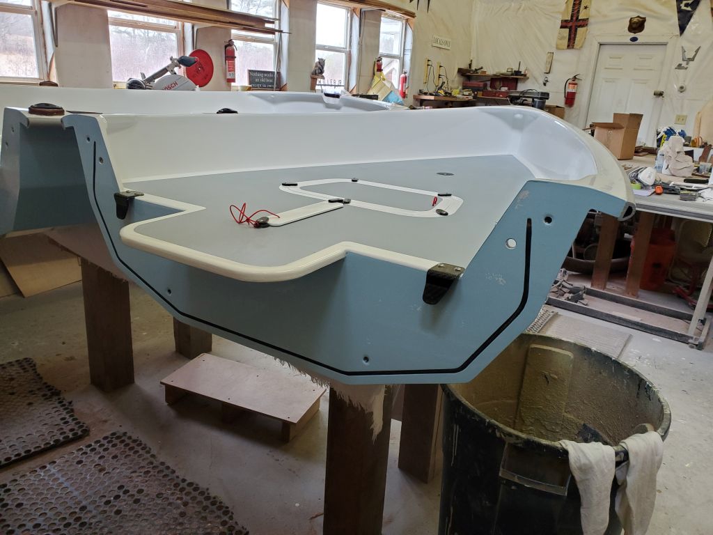
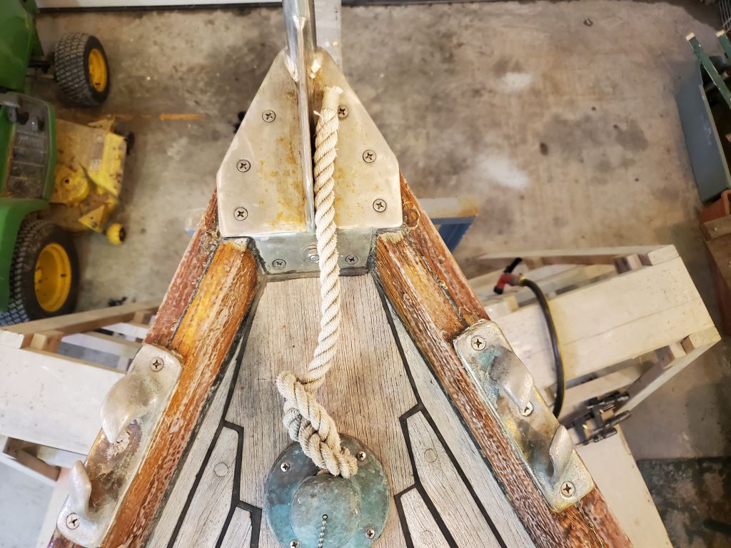
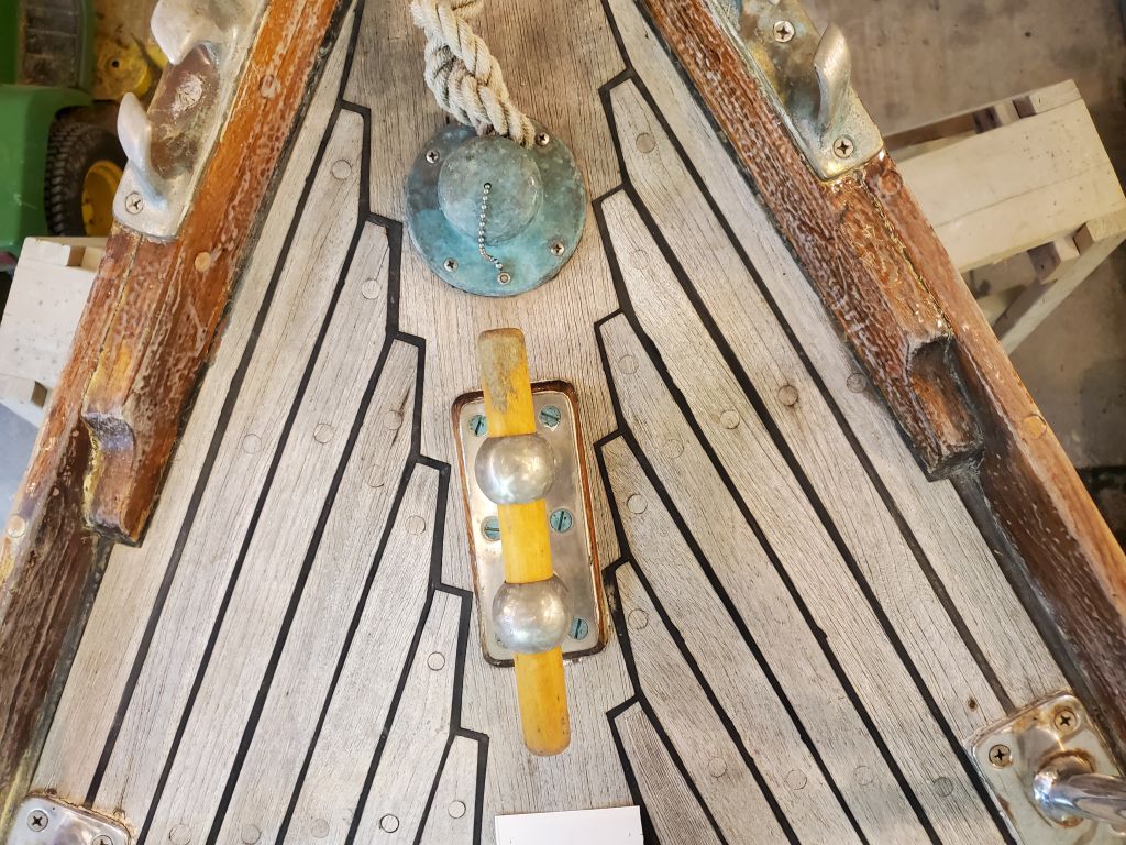
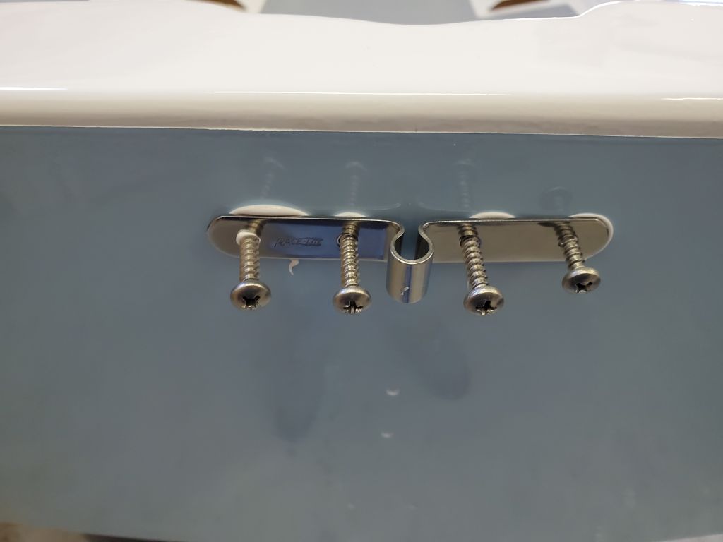
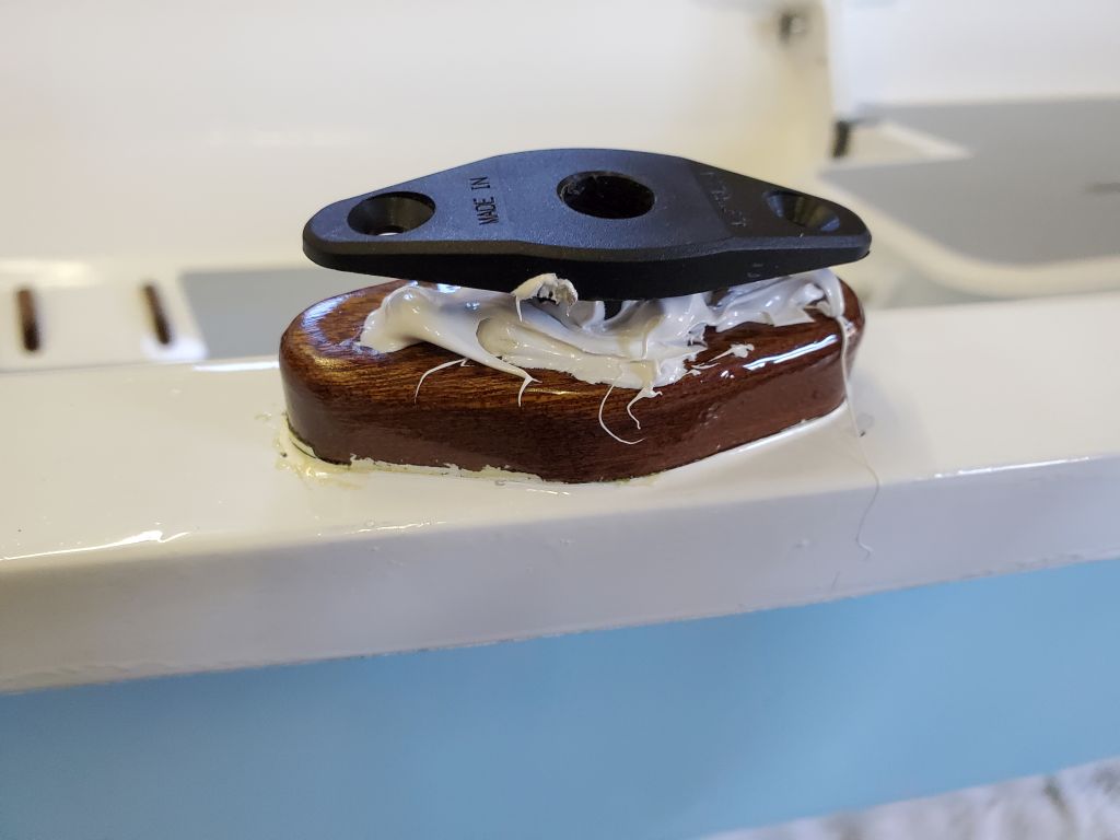
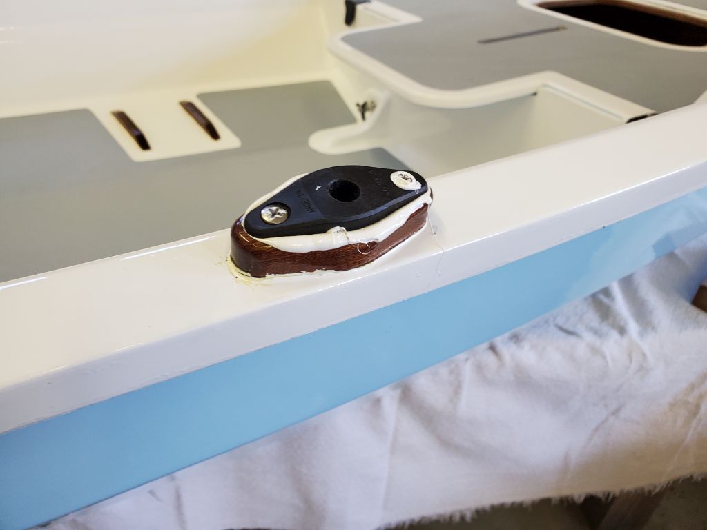
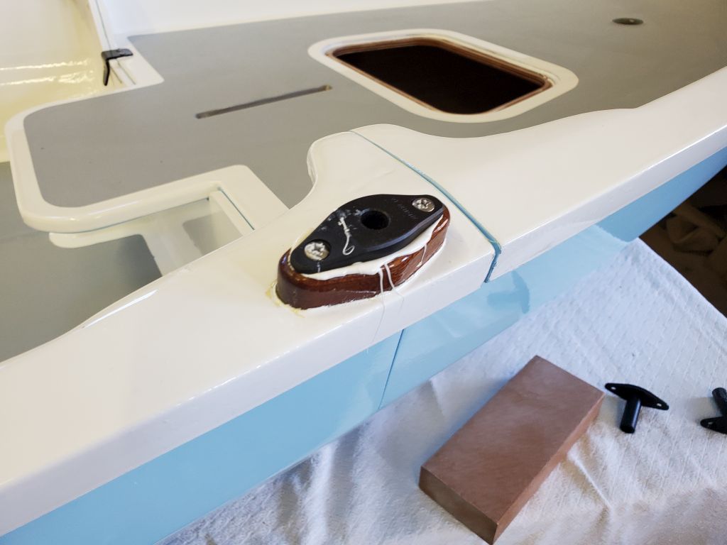
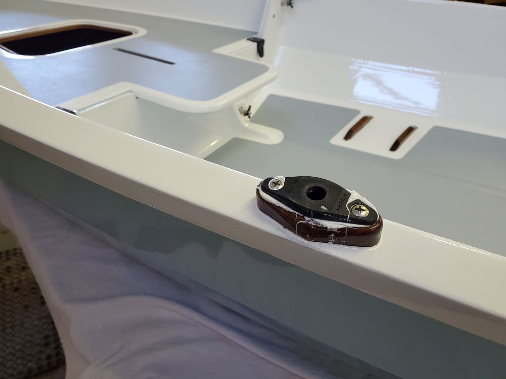
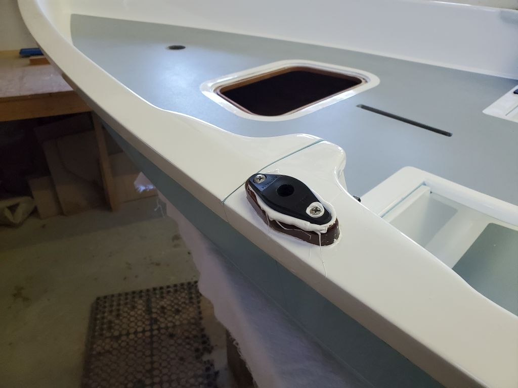
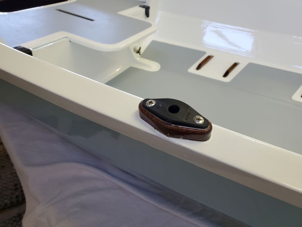
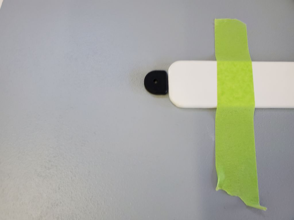
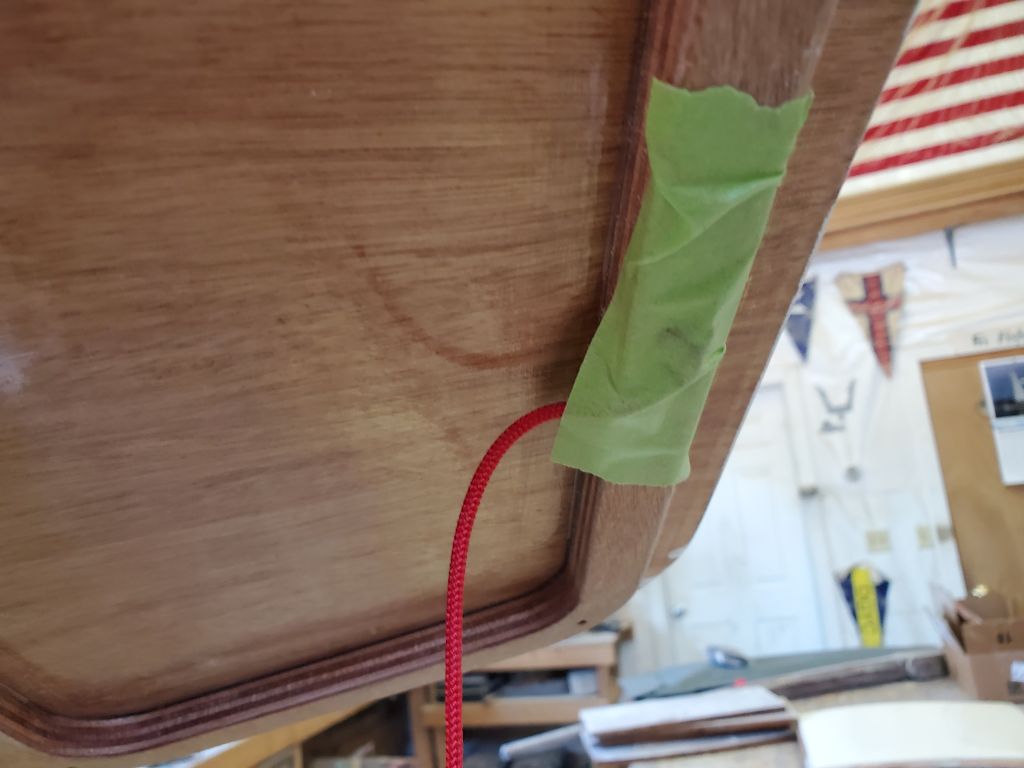
To finish off the aft seat, I secured the other end of the bungee cord to the newly-installed padeye on the deck, and cut off the excess. I left the cord tight, to hold the seat in place, but with enough slack to enable one to lift the seat and store it alongside the starboard aft tank, wedged between the padeye and support cleat, where the seat could be placed when nesting the two dinghy halves.
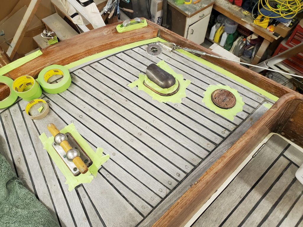
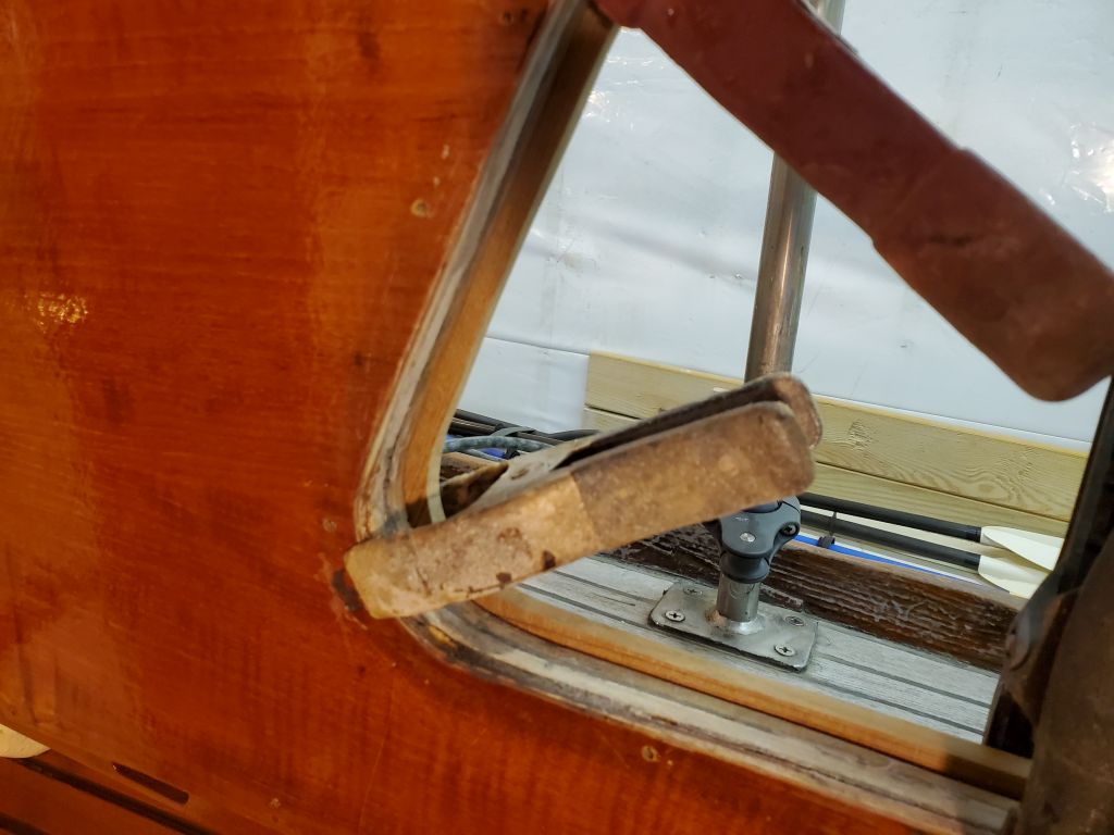
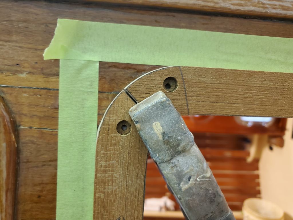
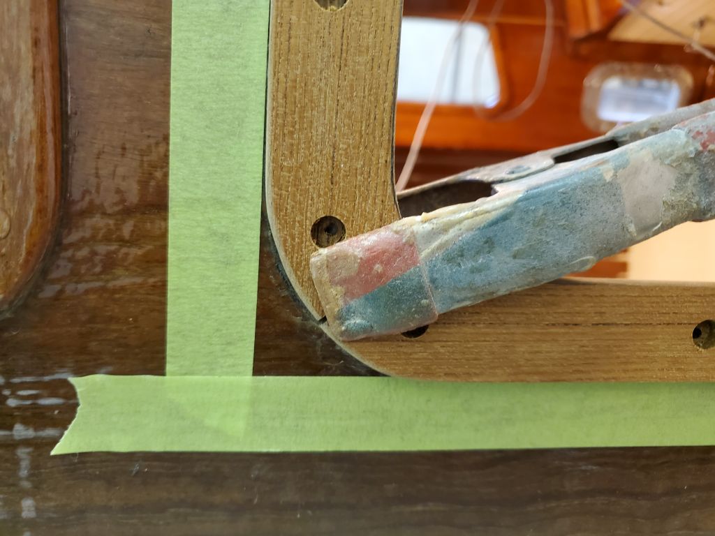
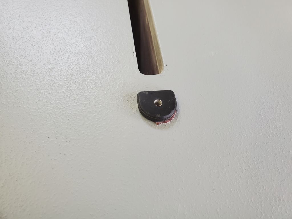
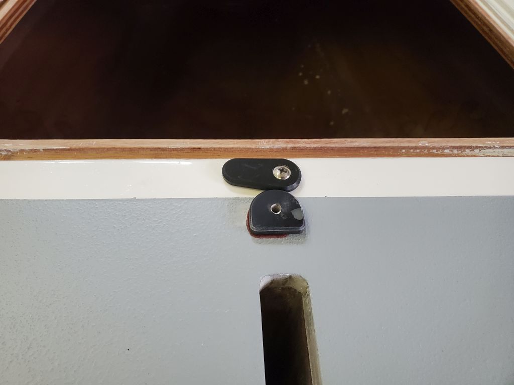
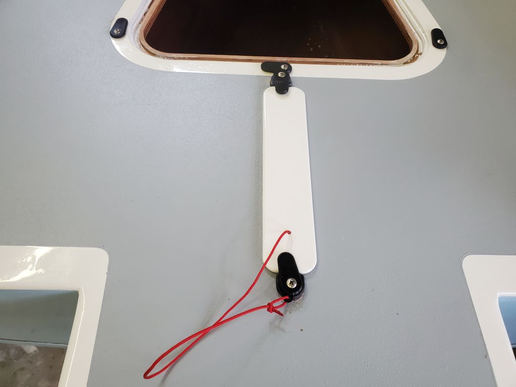
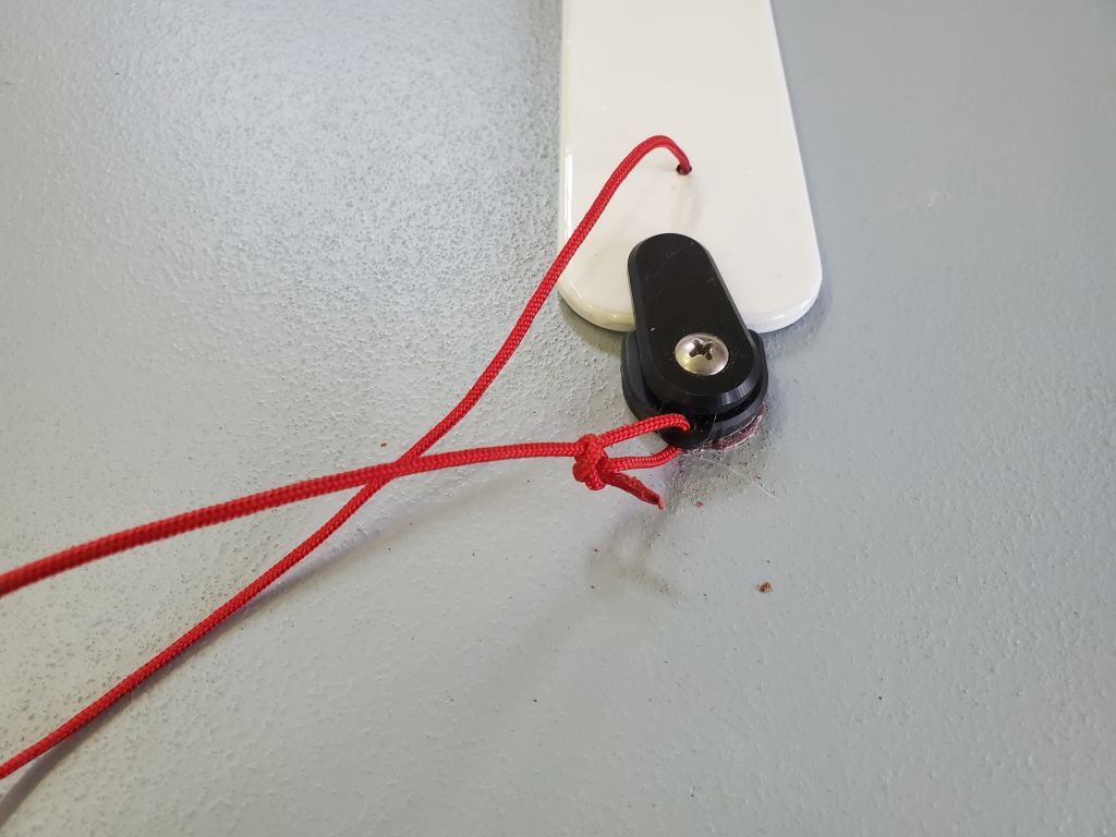
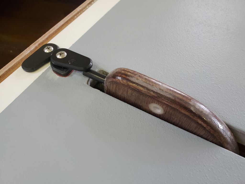
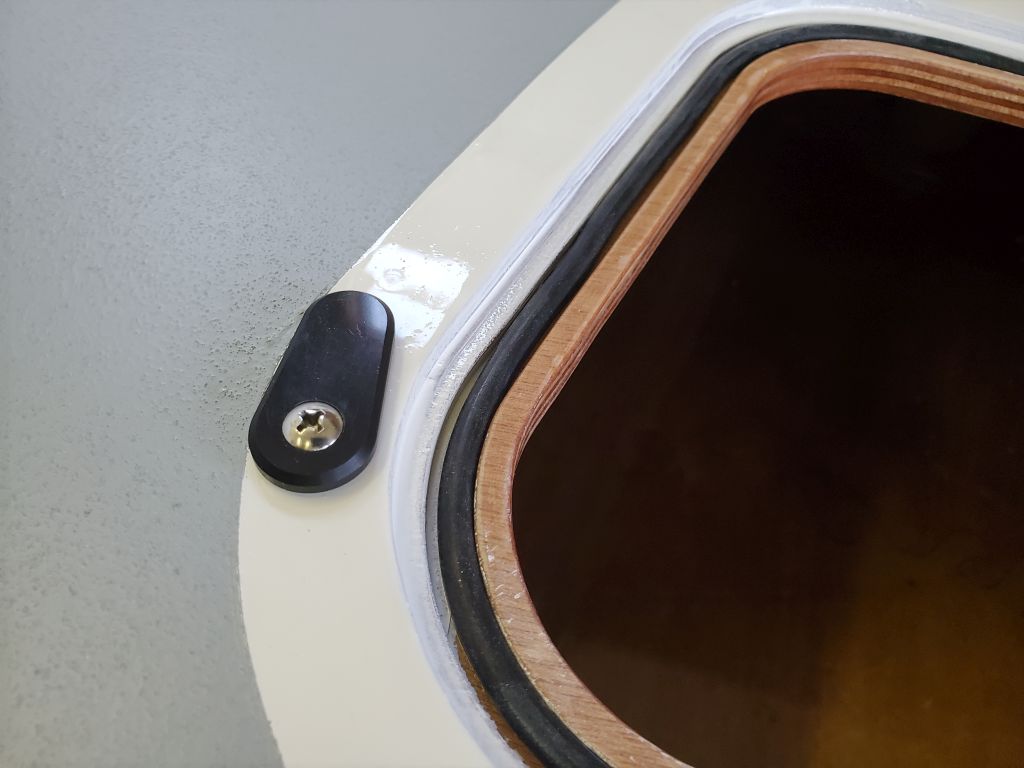
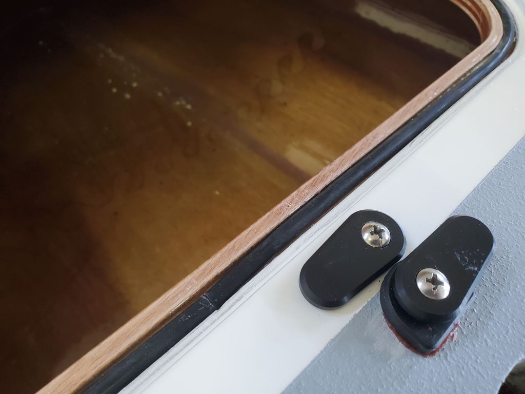
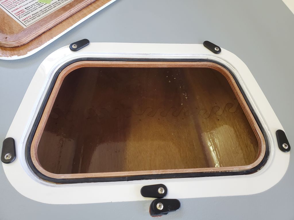
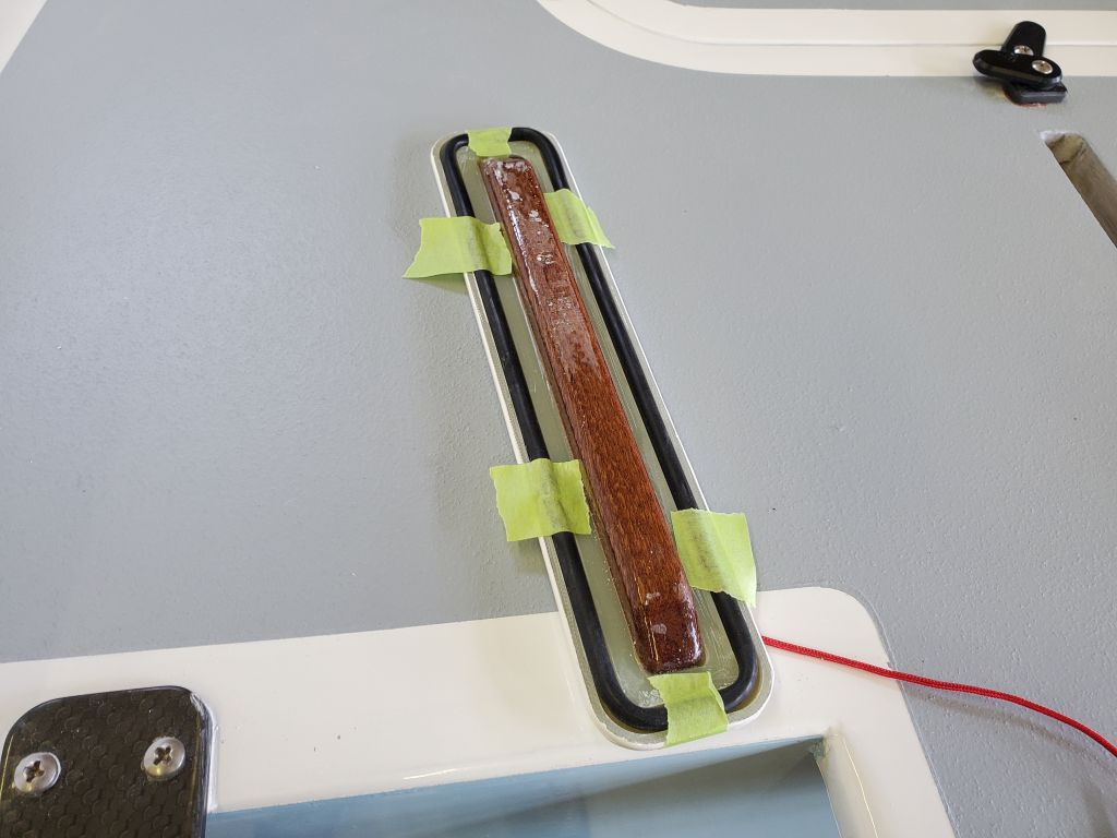
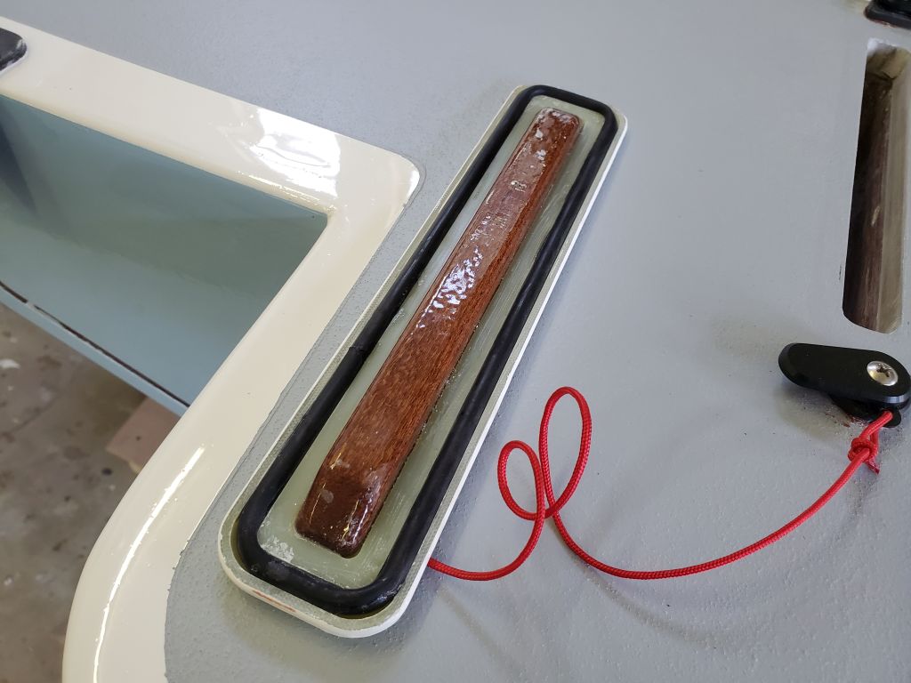
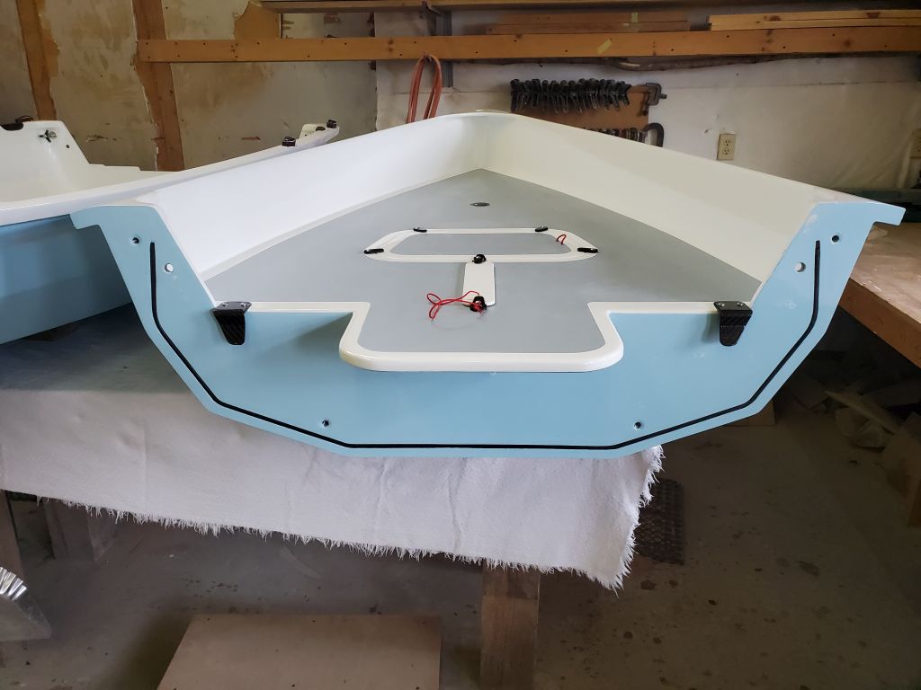
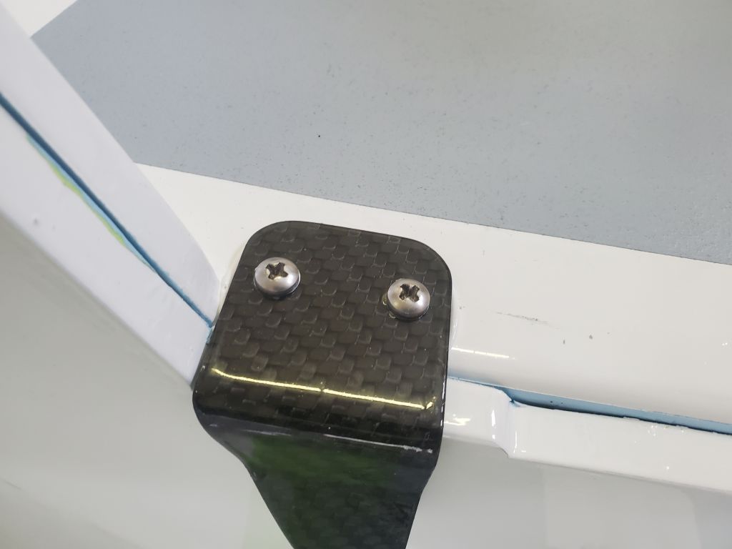
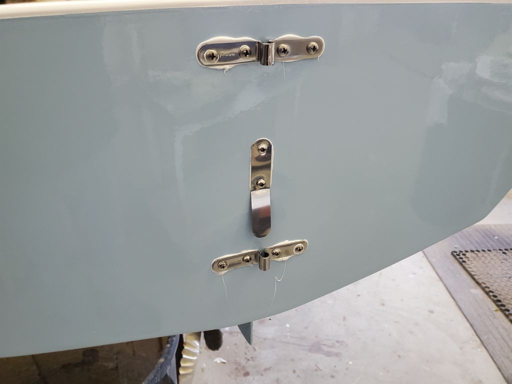
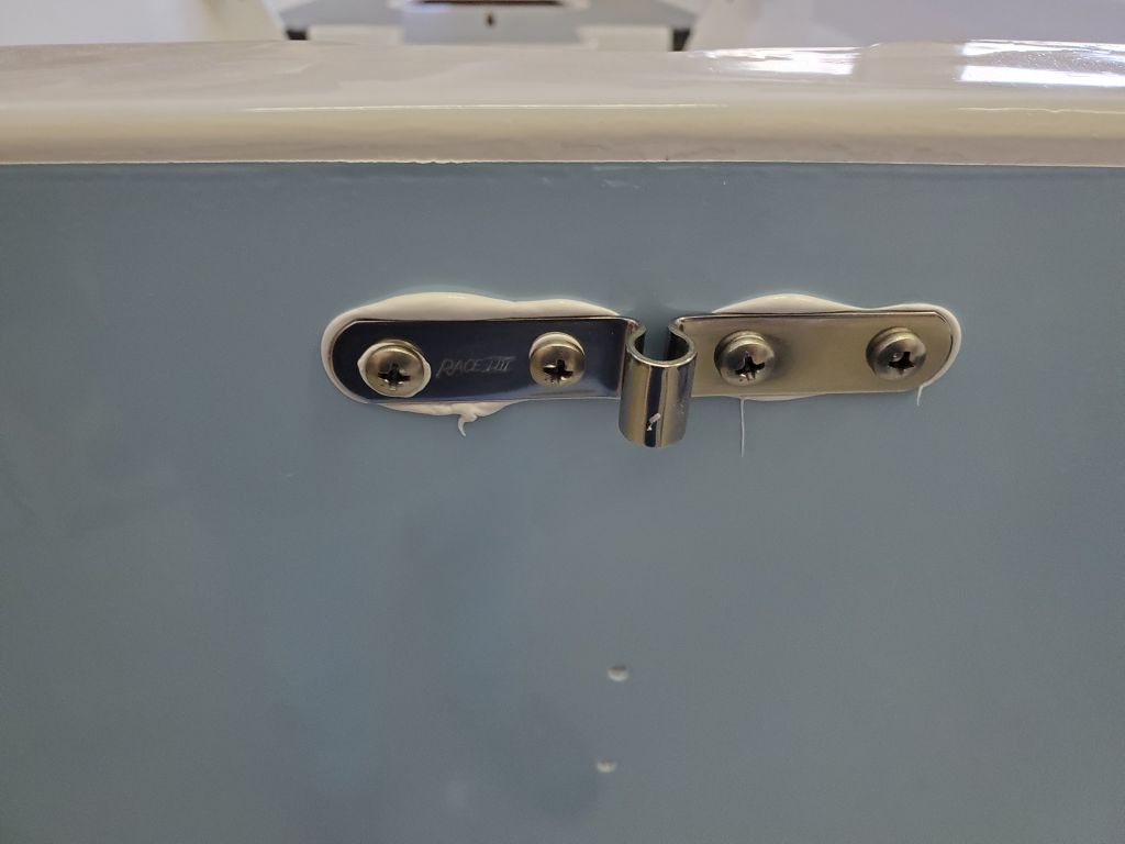
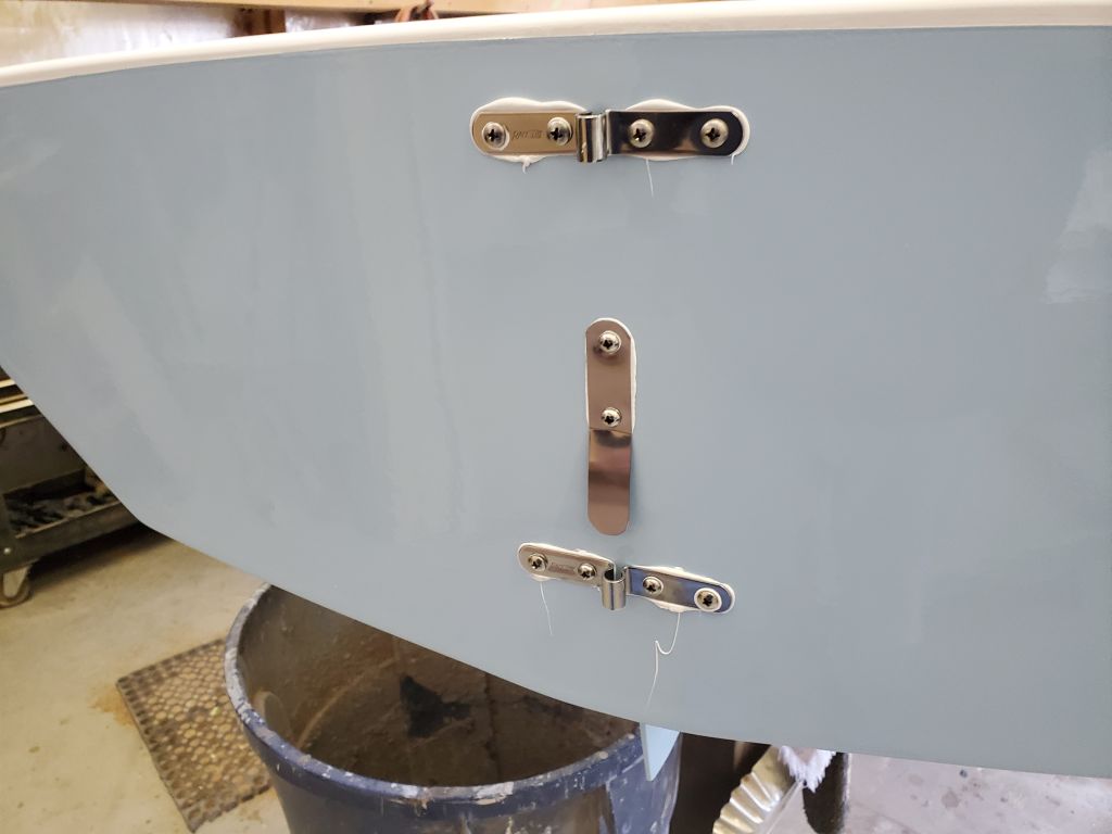
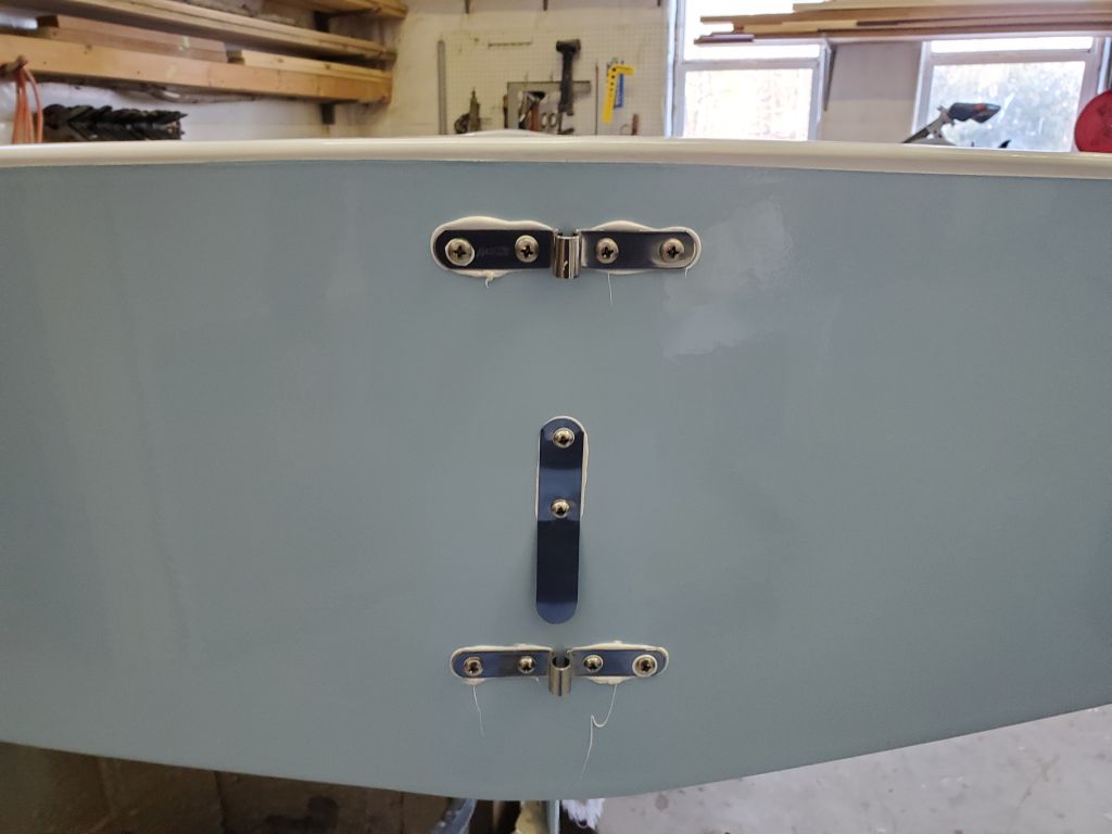
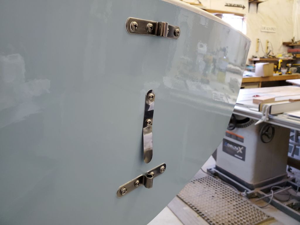
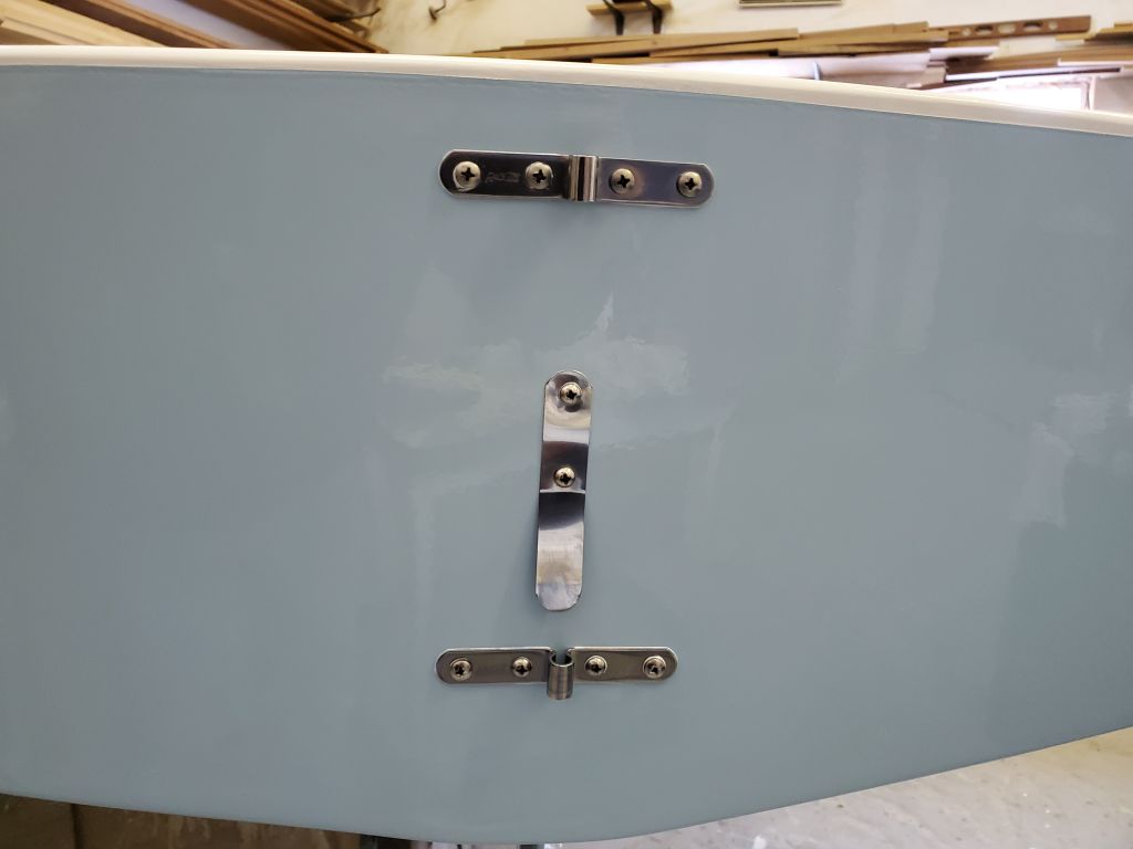
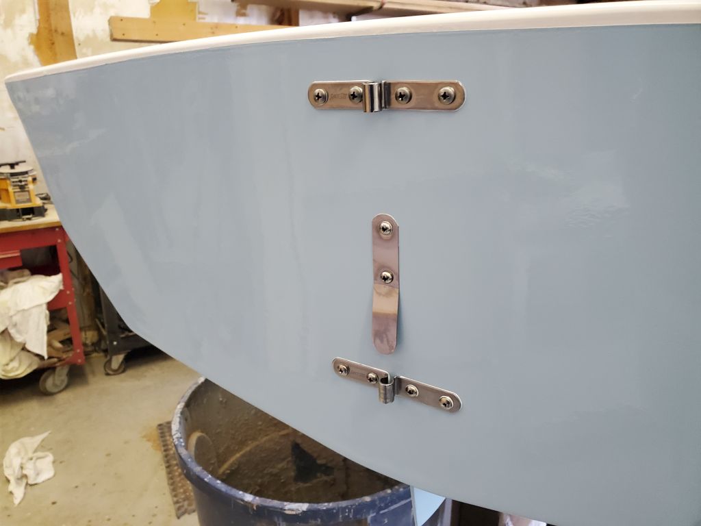
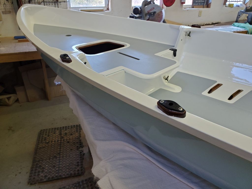
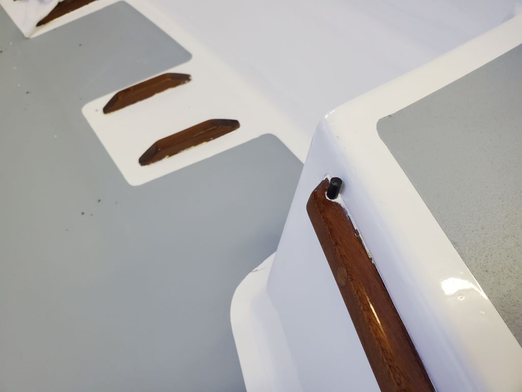
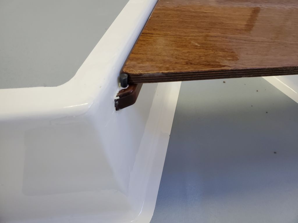
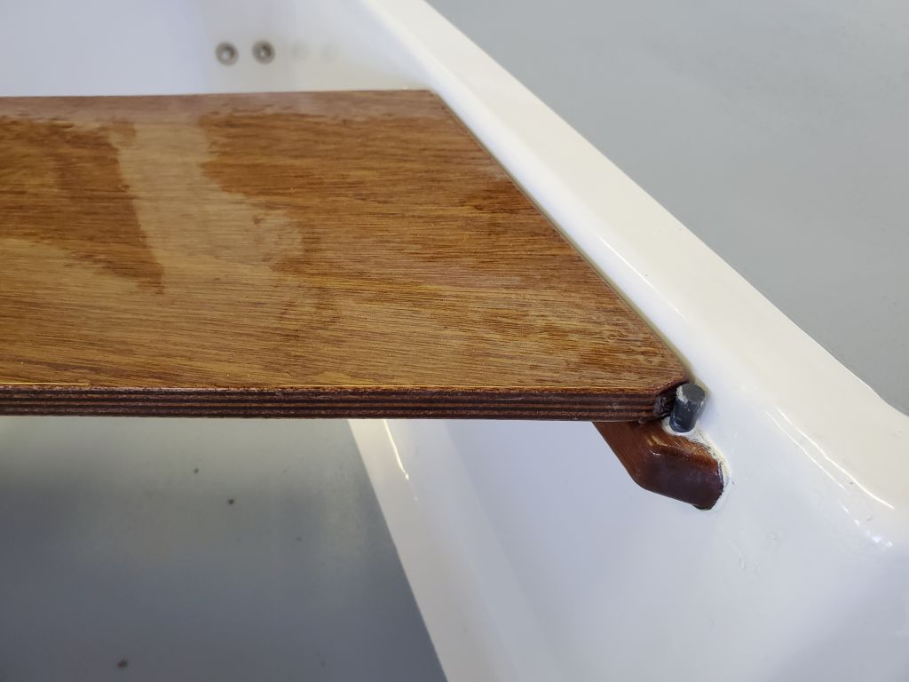
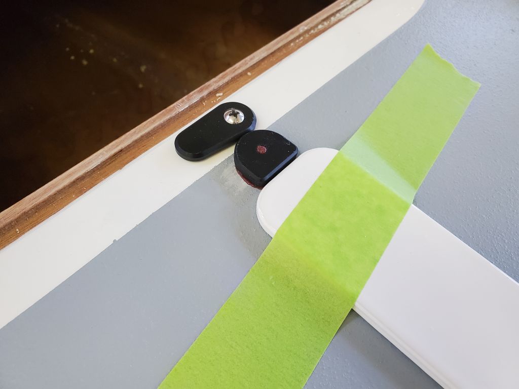
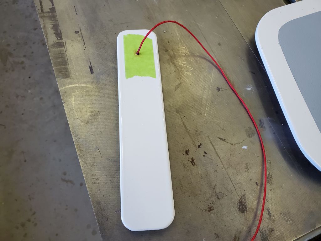
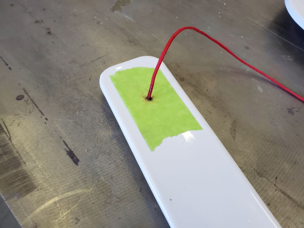
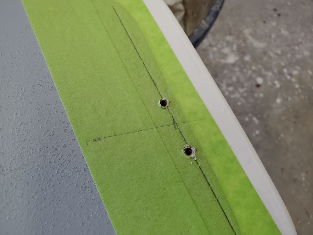
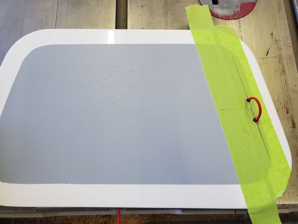
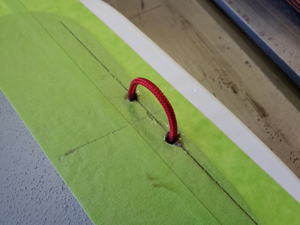
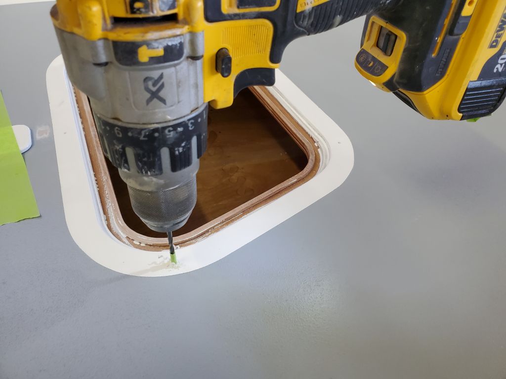
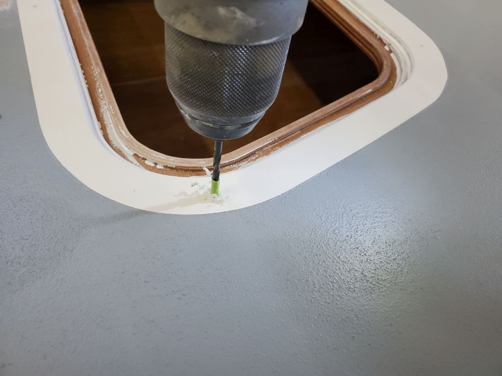
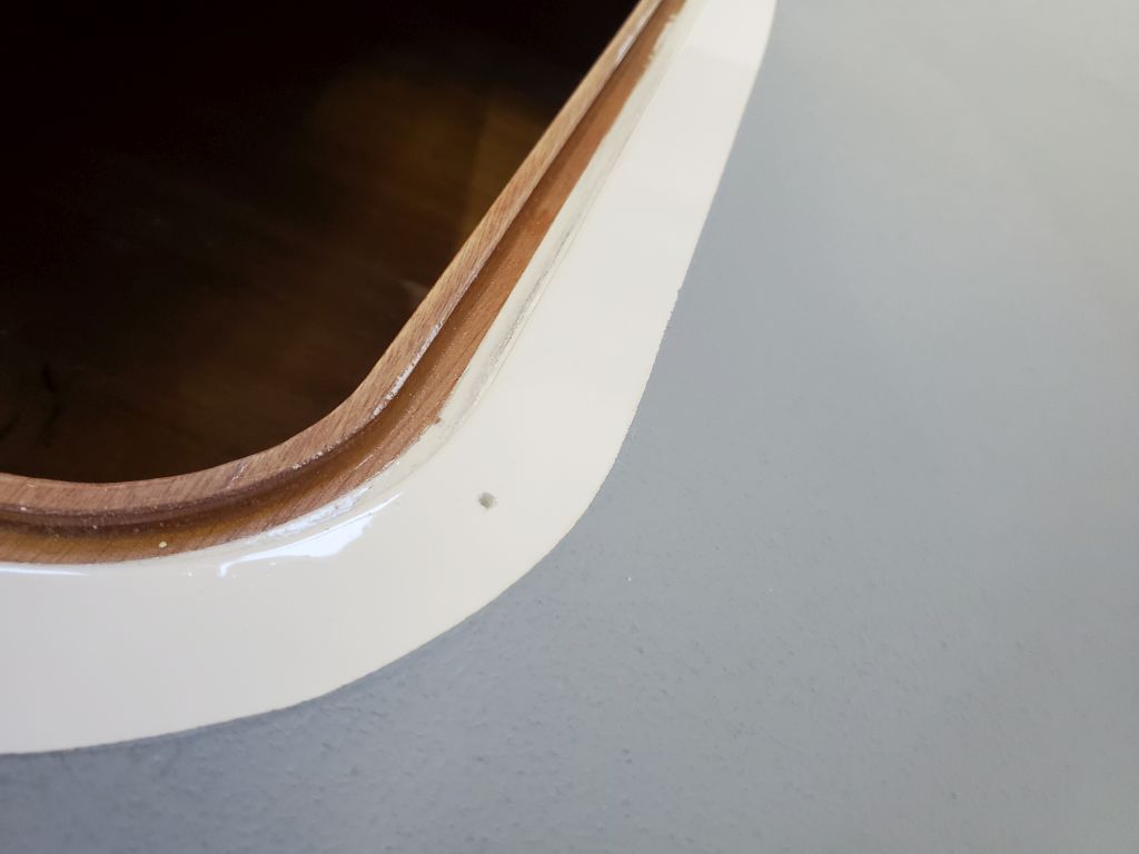
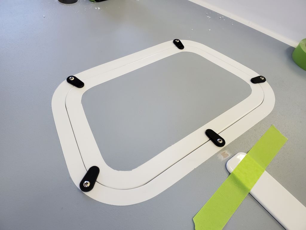
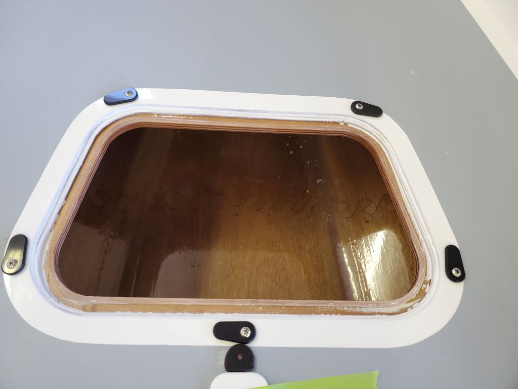
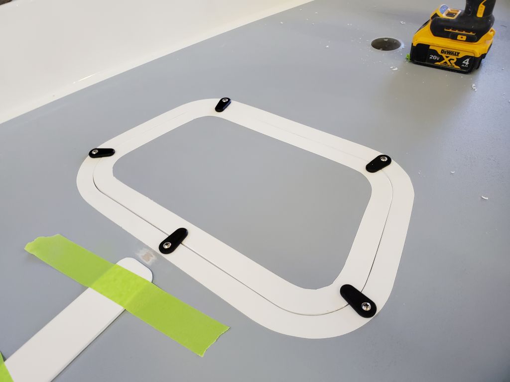
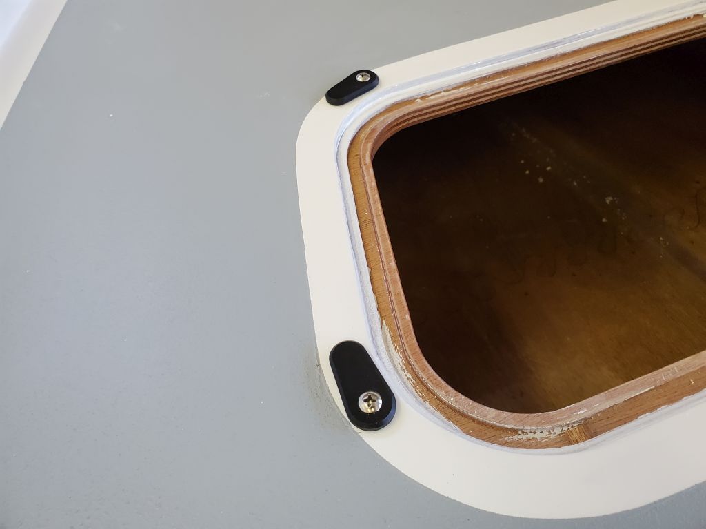
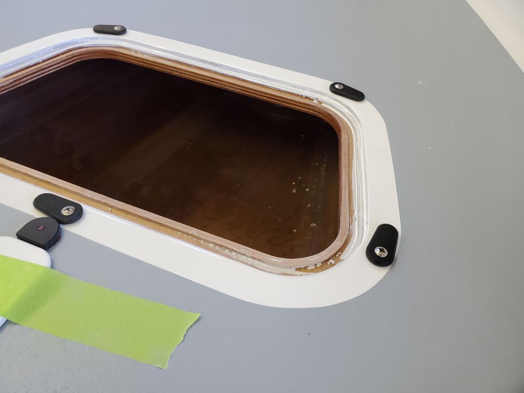
Now that the risers on each end of the daggerboard trunk were cured, I drilled the mounting holes for the turn dogs, and installed the latches the same way as with the forward hatch, with some epoxy in the screw hole to secure the screw, and the screw tensioned just enough that the turn dog could still move. This pair of latches included slim plastic washers beneath, for clearance, and the after washer included an extra tab with a hole to which I could secure the lanyard from the cover. The forward latch doubled as a hold-down for the pin that I’d installed in the leading edge of the daggerboard earlier; the daggerboard still needed a short loop of line to secure to the hole in the top of the board and provide a grip for installing and removing the board.
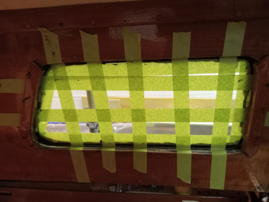
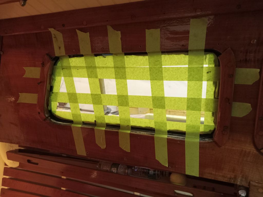
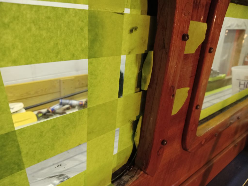
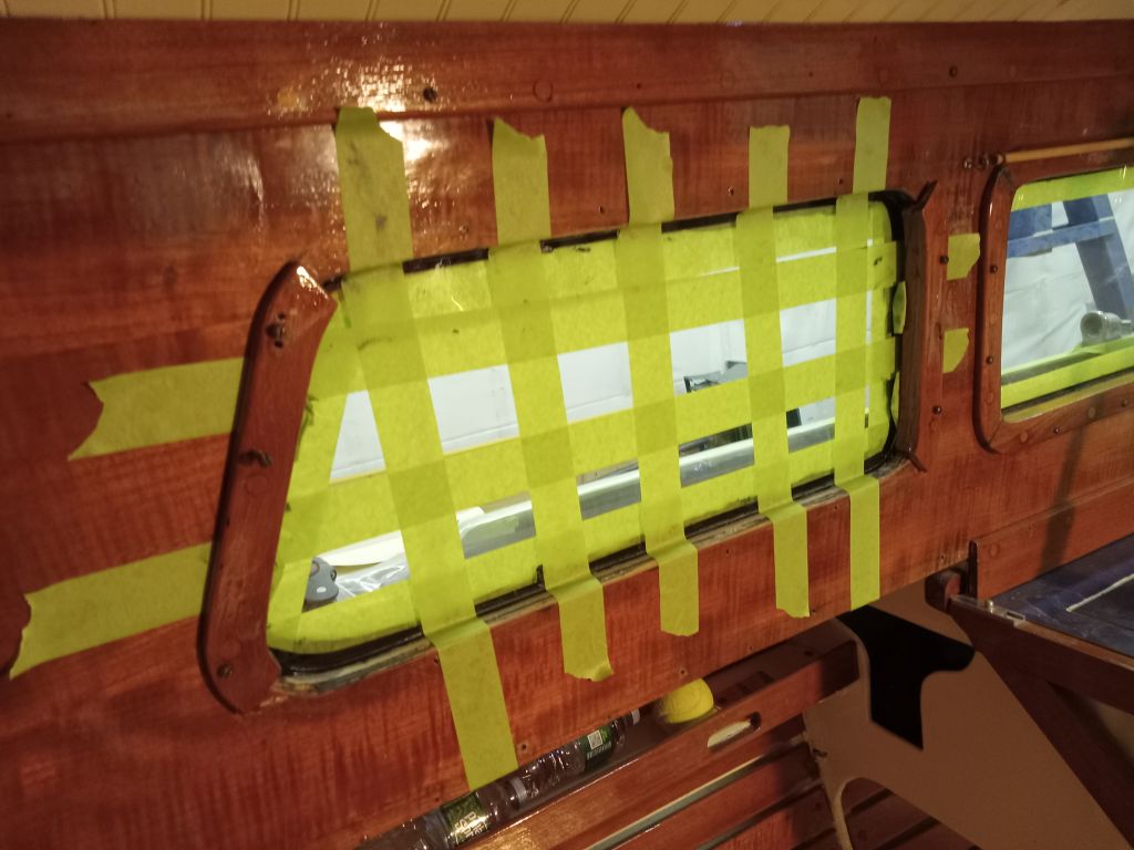
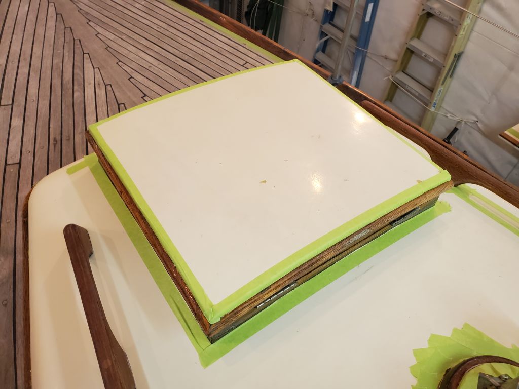
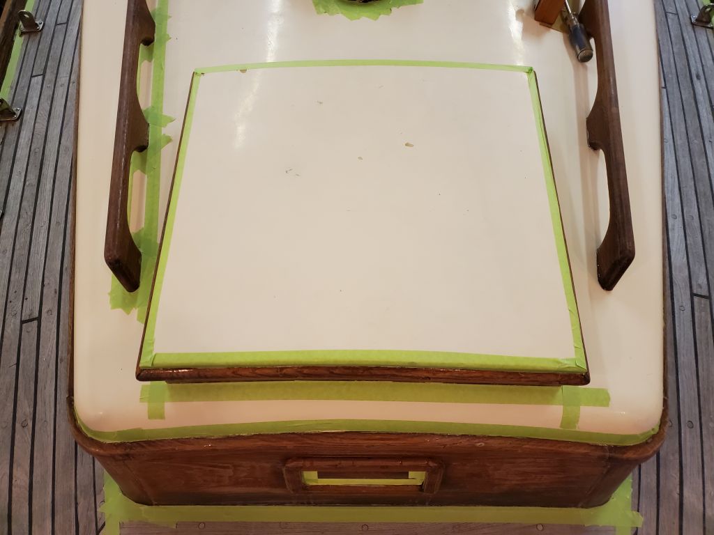
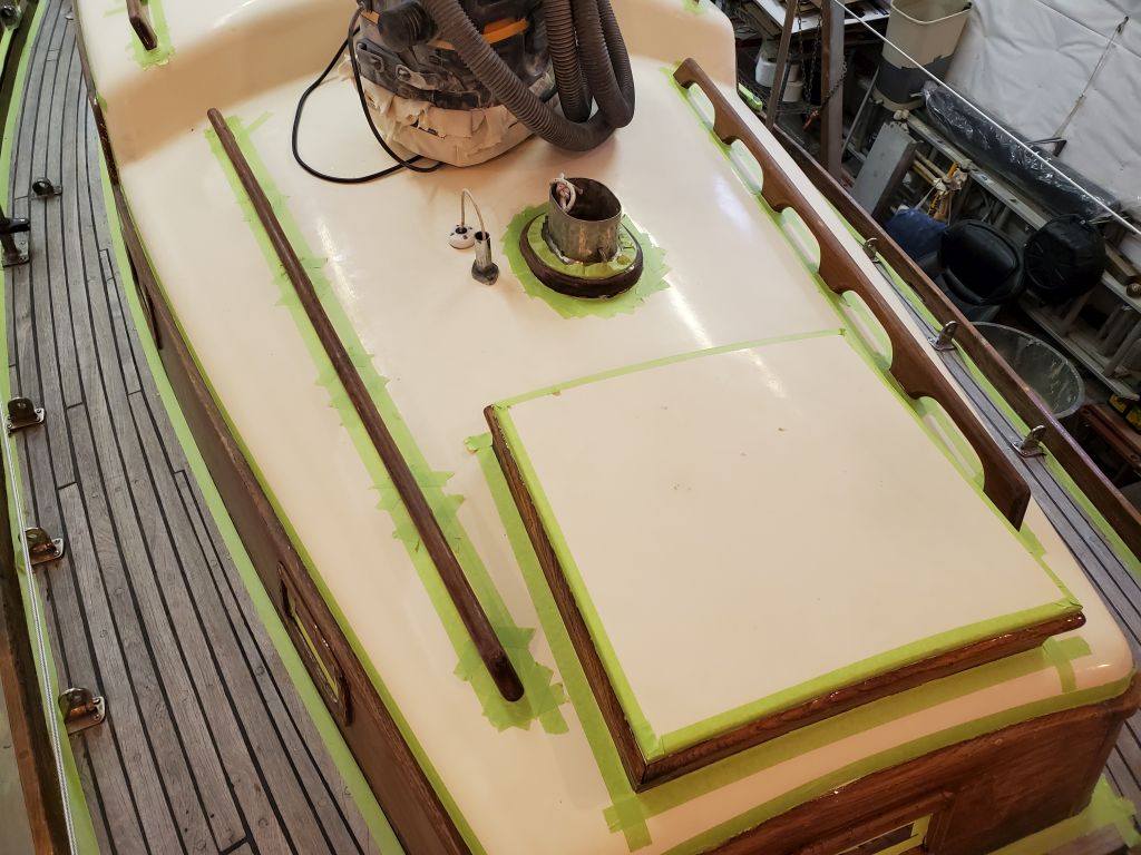
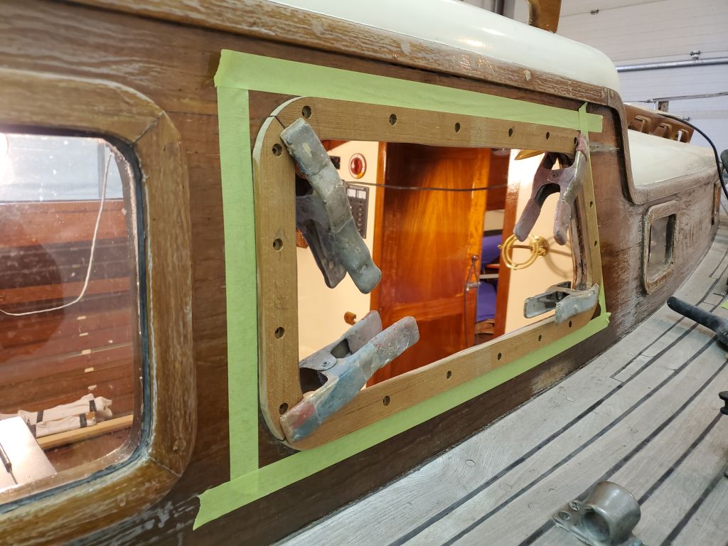
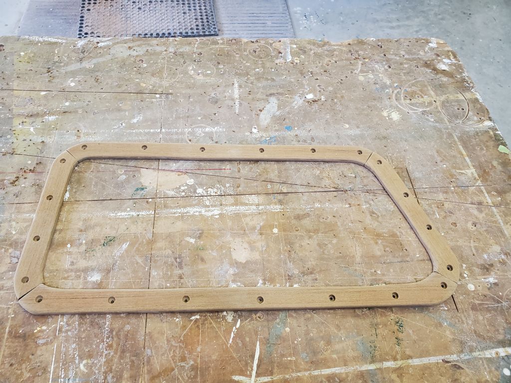
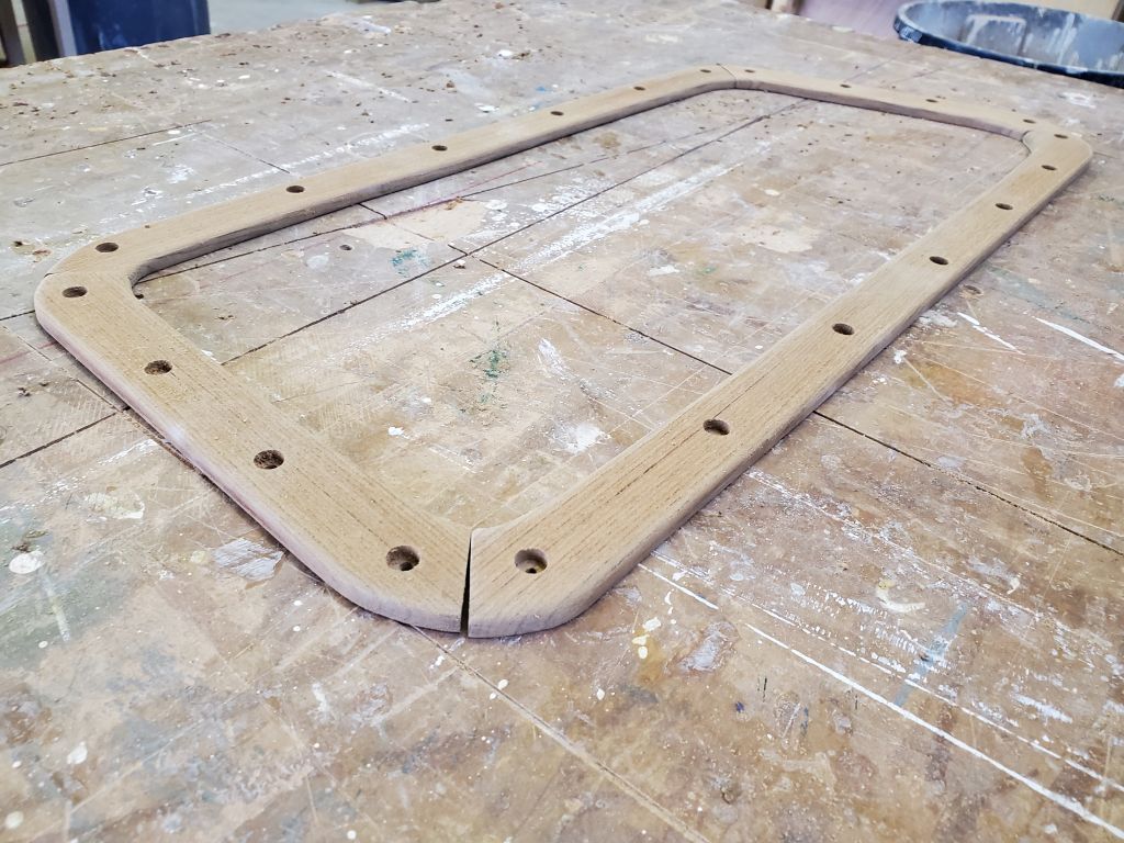
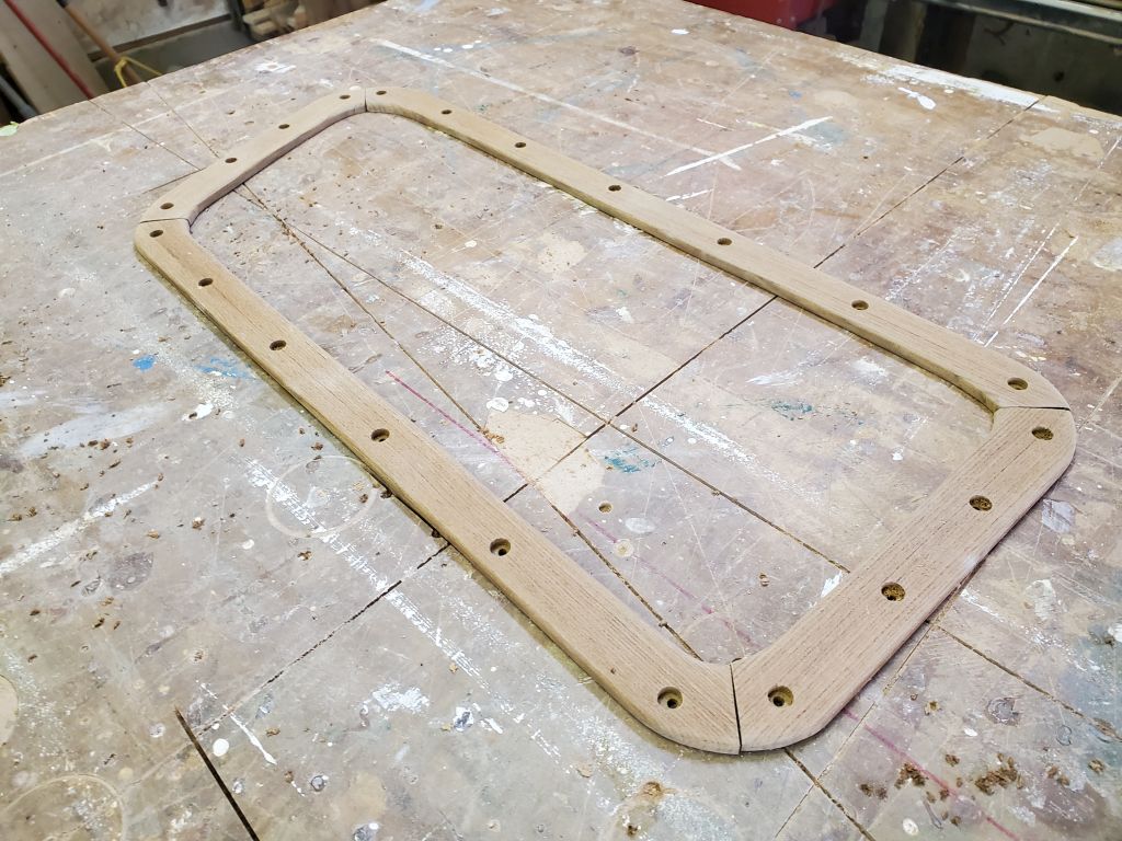
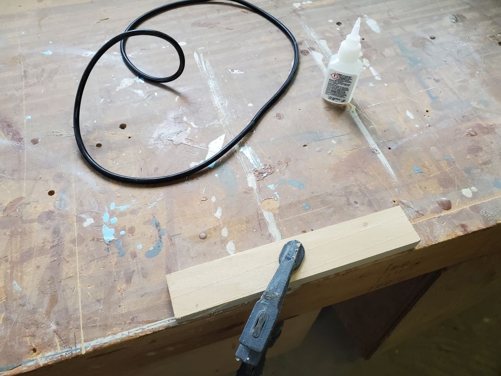
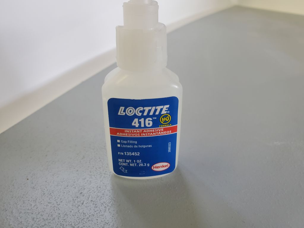
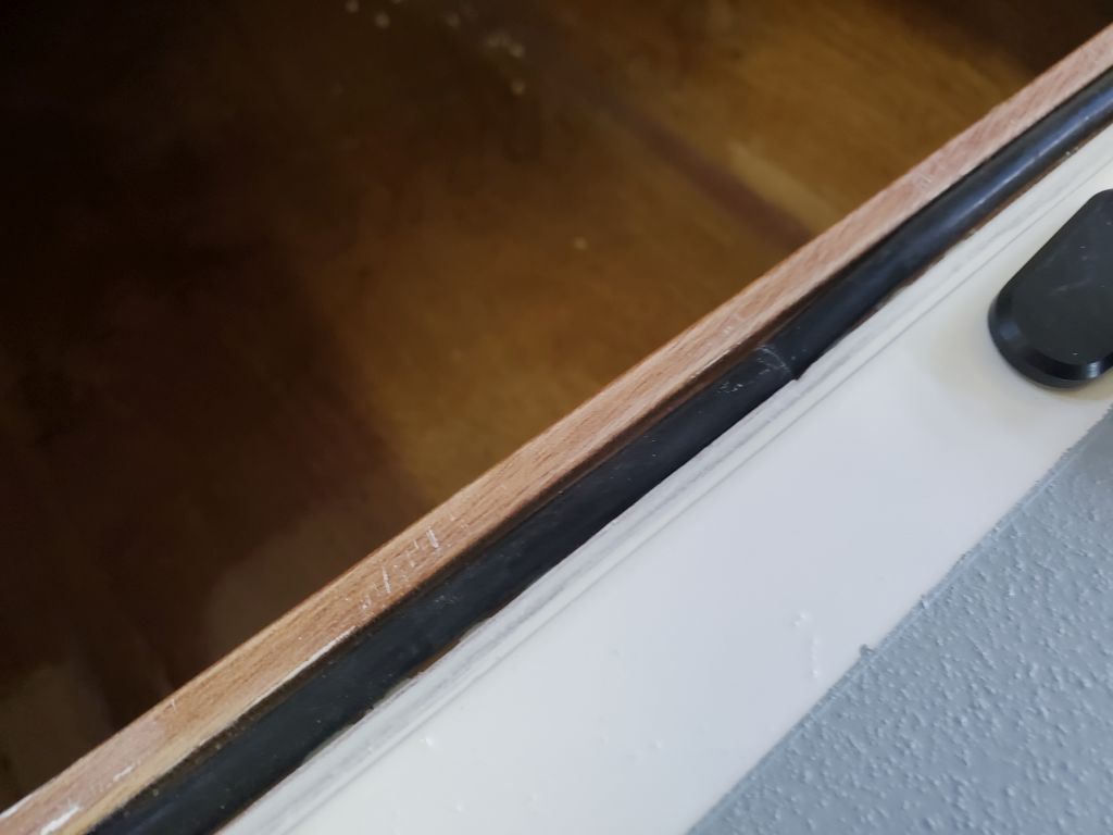
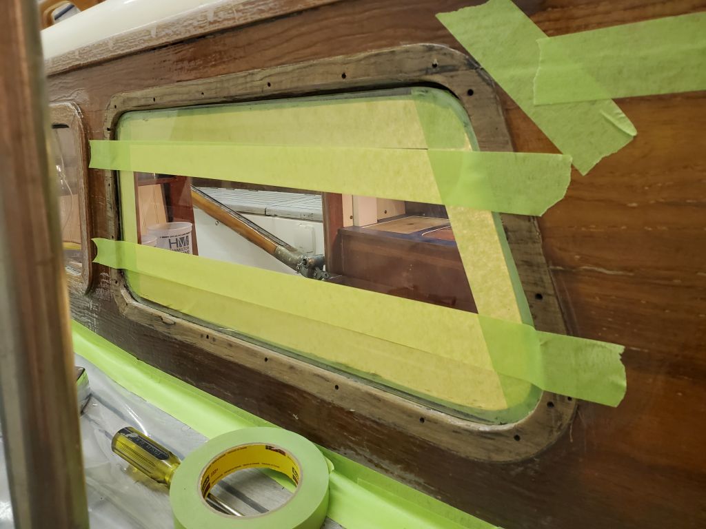
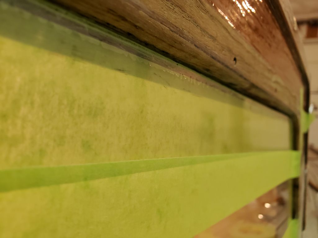
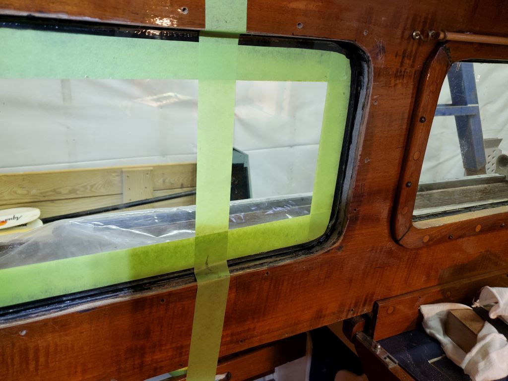
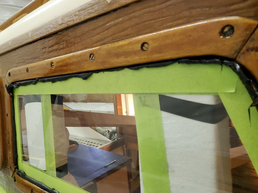
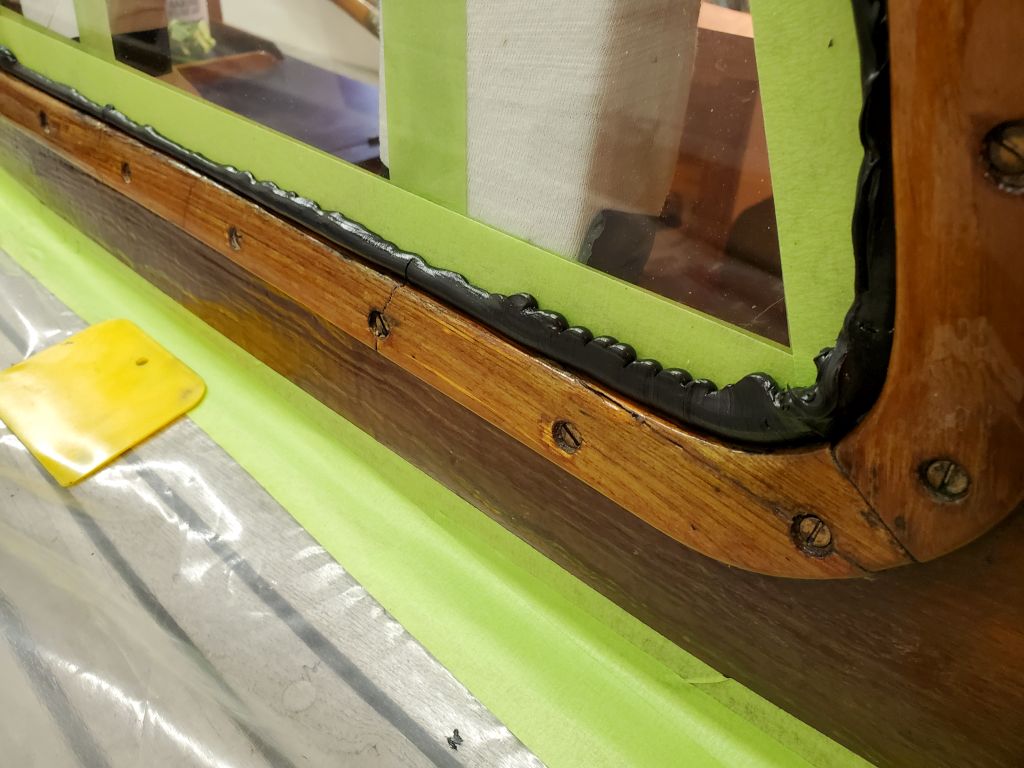
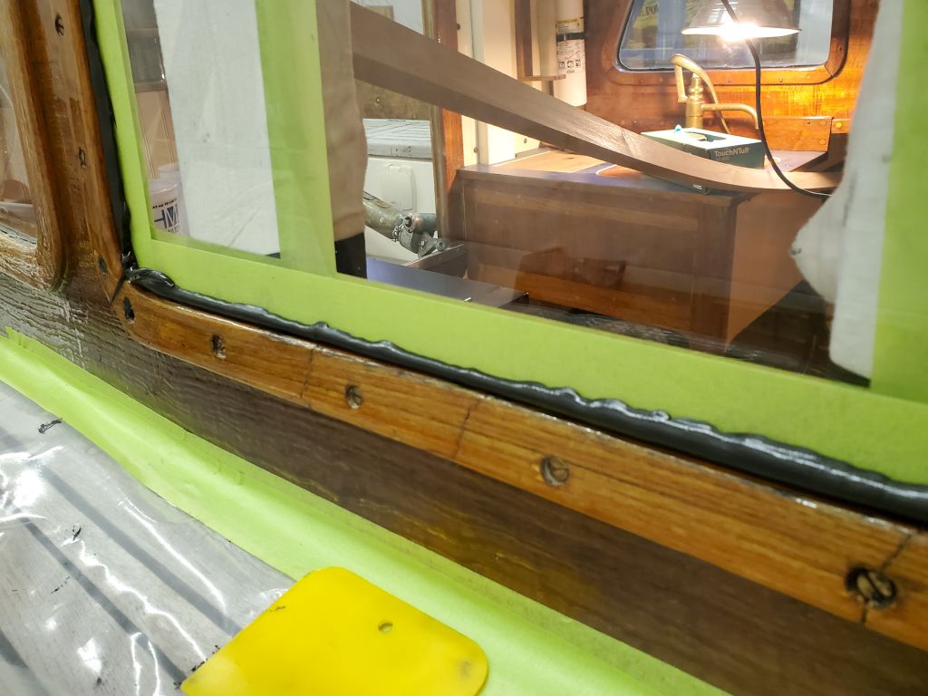
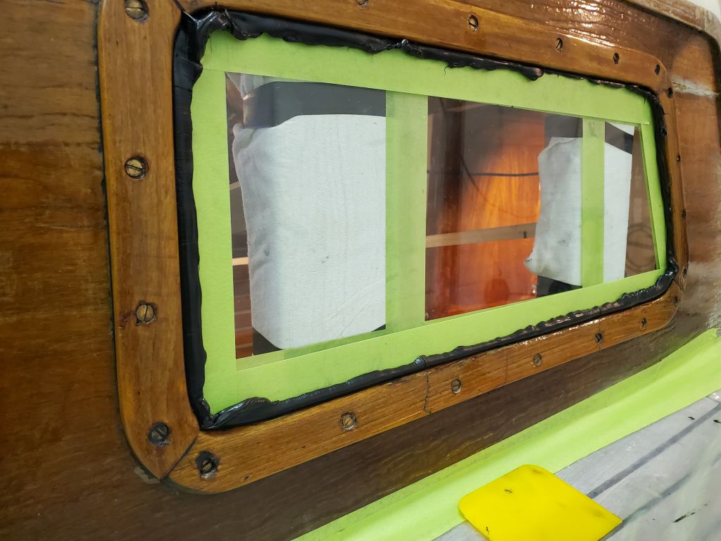
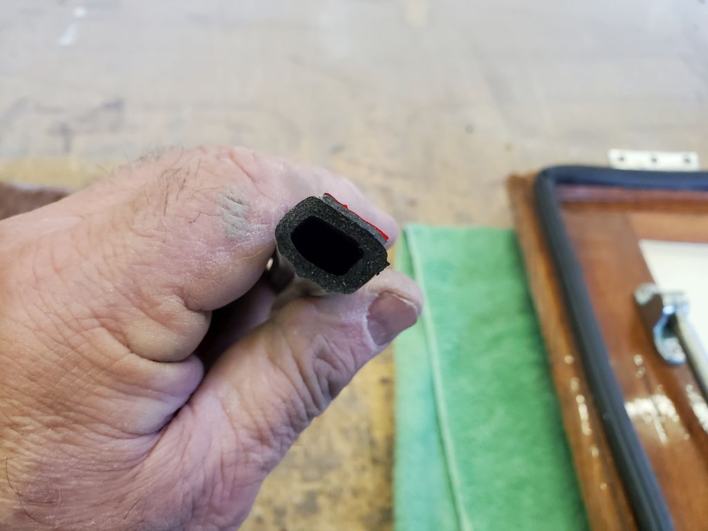
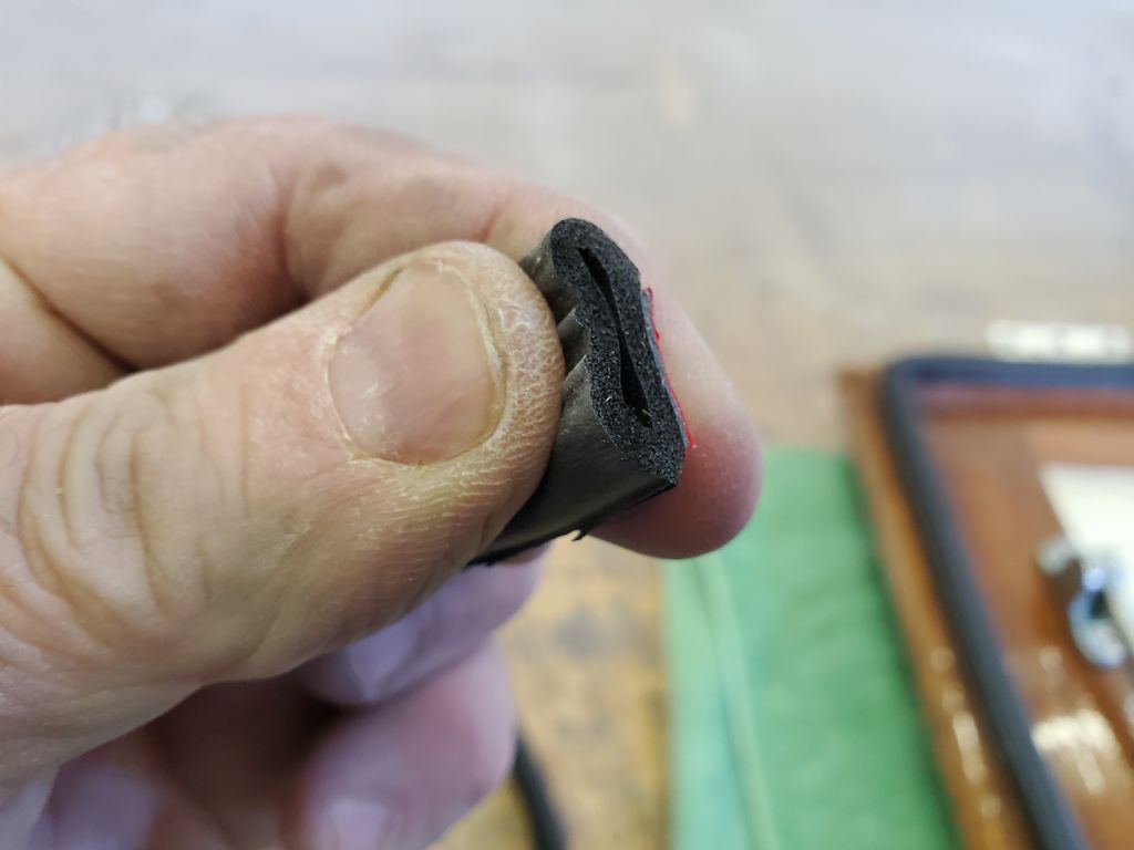
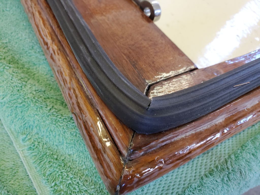
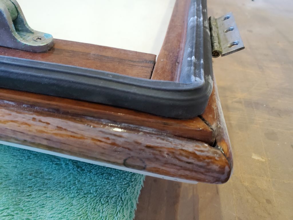
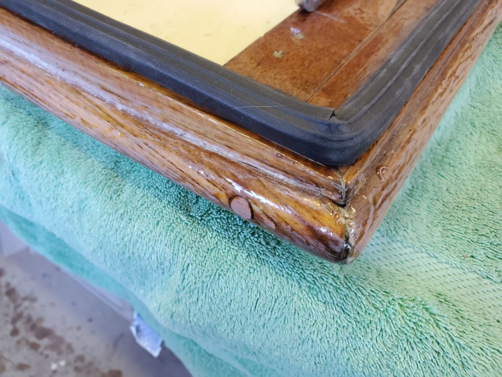
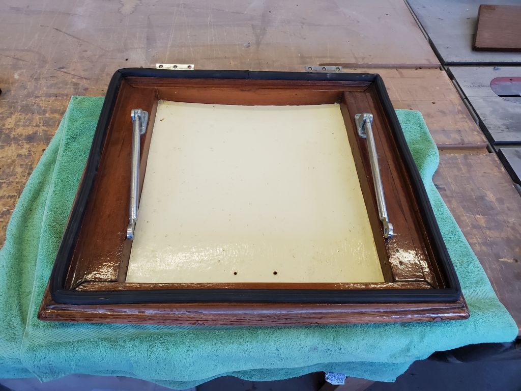
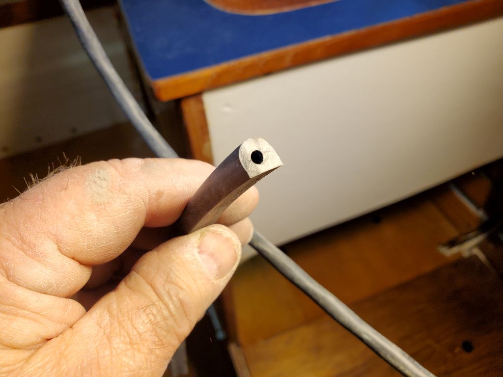
Next in the rapidly-dwindling list of remaining tasks was the watertight gaskets required for the forward hatch, daggerboard lid, and the forward hull bulkhead. These gaskets were made from 1/4″ surgical tubing and the book recommended thick-style cyanoacrylate glue (super glue) as the best method for securing them in their respective grooves.
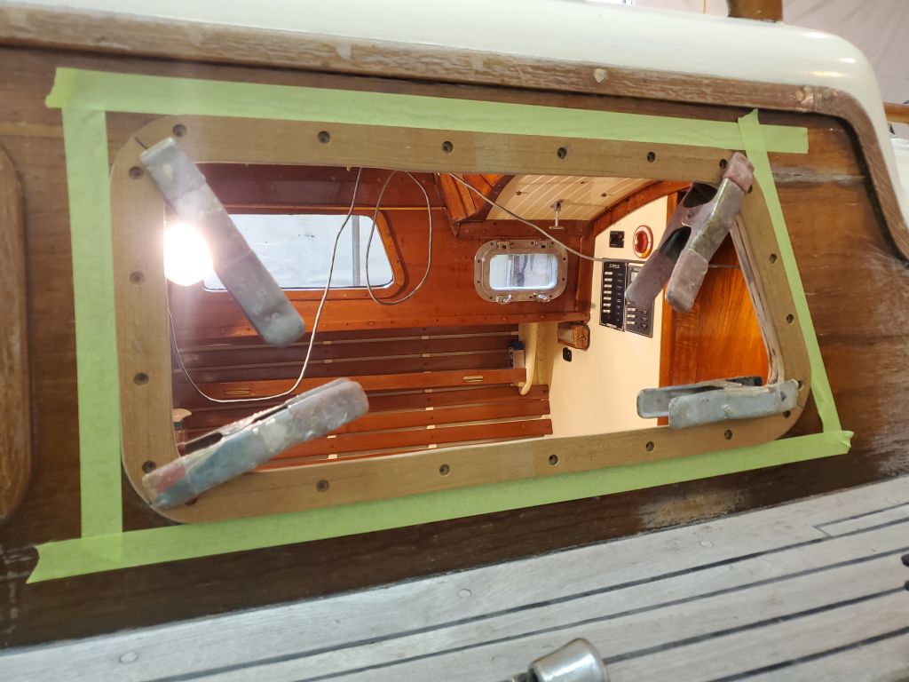
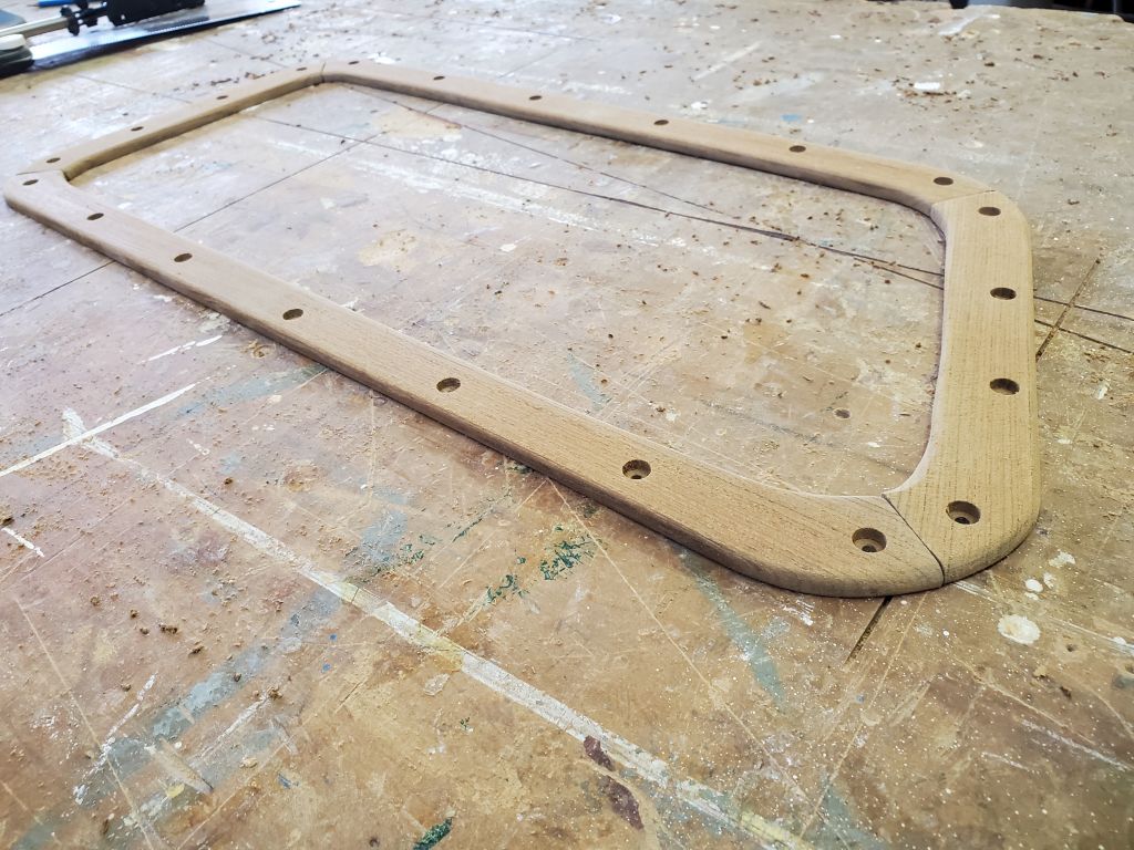
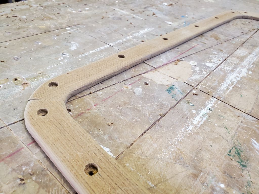
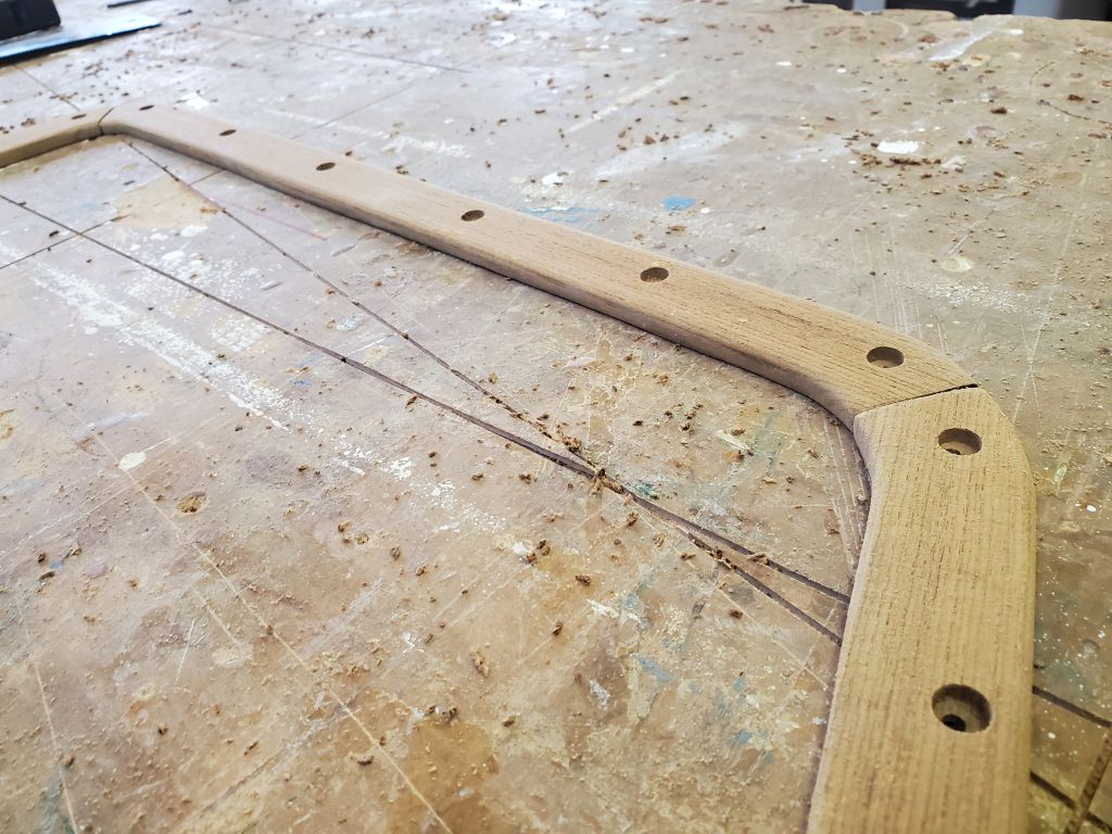
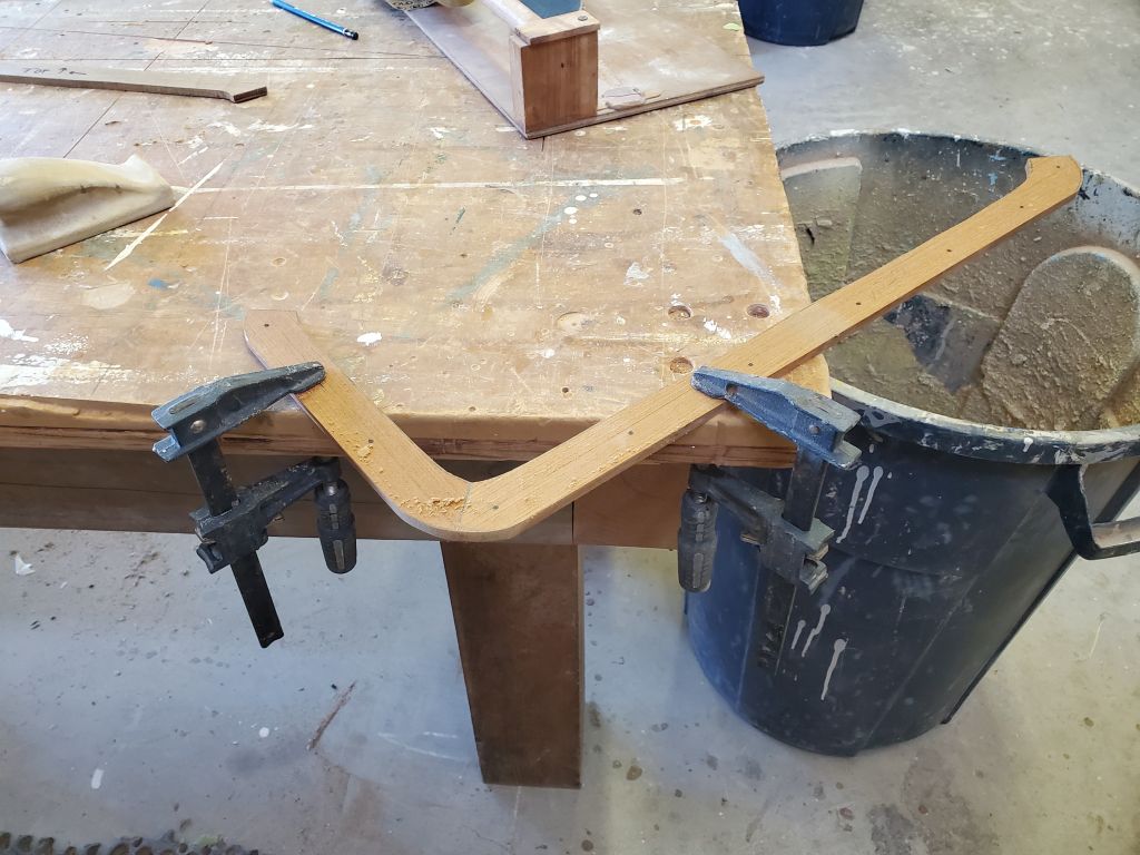
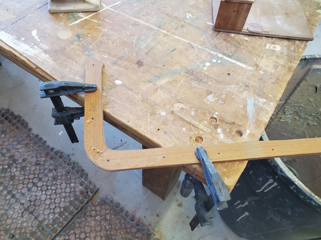
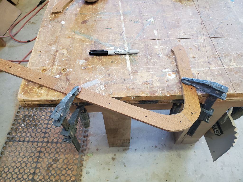
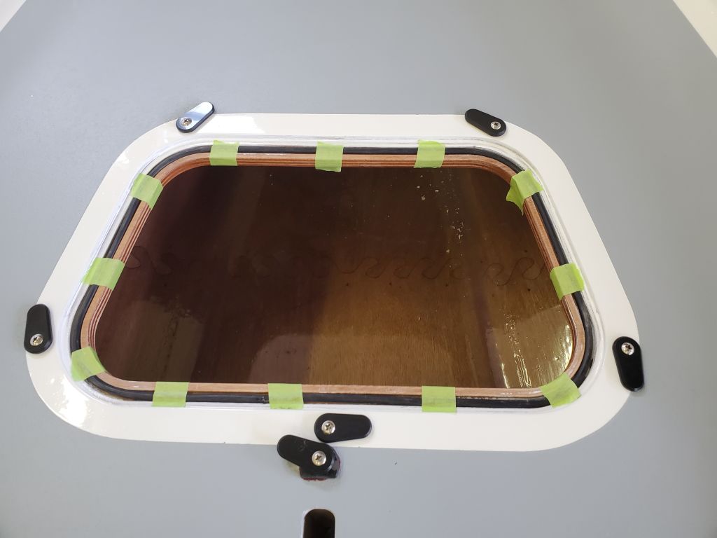
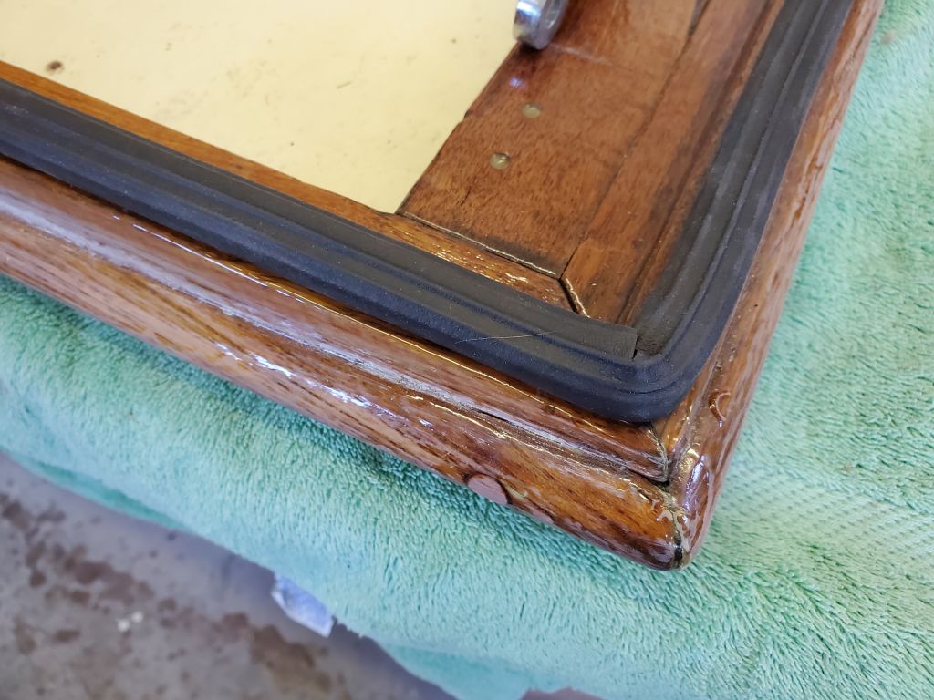
I started with the forward hatch gasket, and dry-fit the tubing to determine its final length; afterwards, I butt-glued the two ends together in a simple corner jig made from a block of wood clamped to the bench, with plastic tape against both surfaces; this allowed me to easily hold the two ends together and in alignment when gluing, and thus creating a one-piece gasket for both the forward hatch and, later, the daggerboard. This worked well. Then, I taped the gasket in place in its grove to hold it and allow me to incrementally glue it in place by lifting one section at a time around the opening.
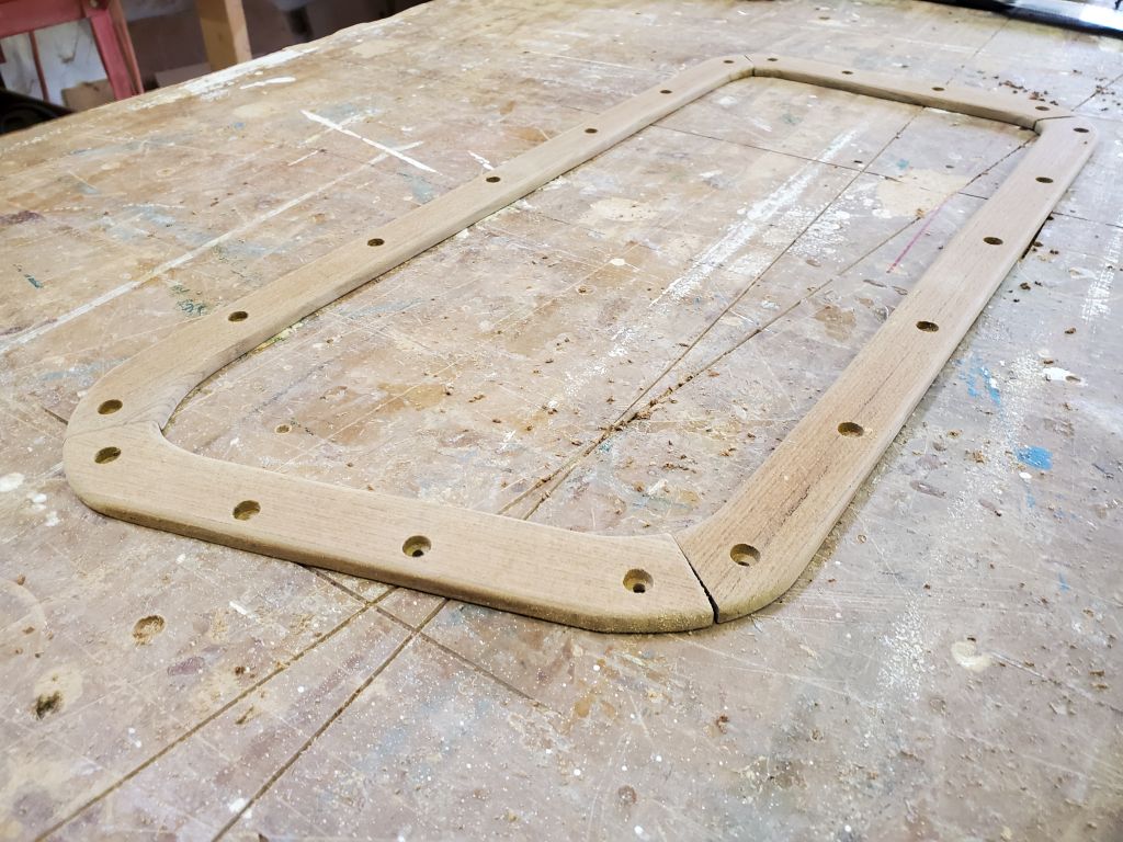
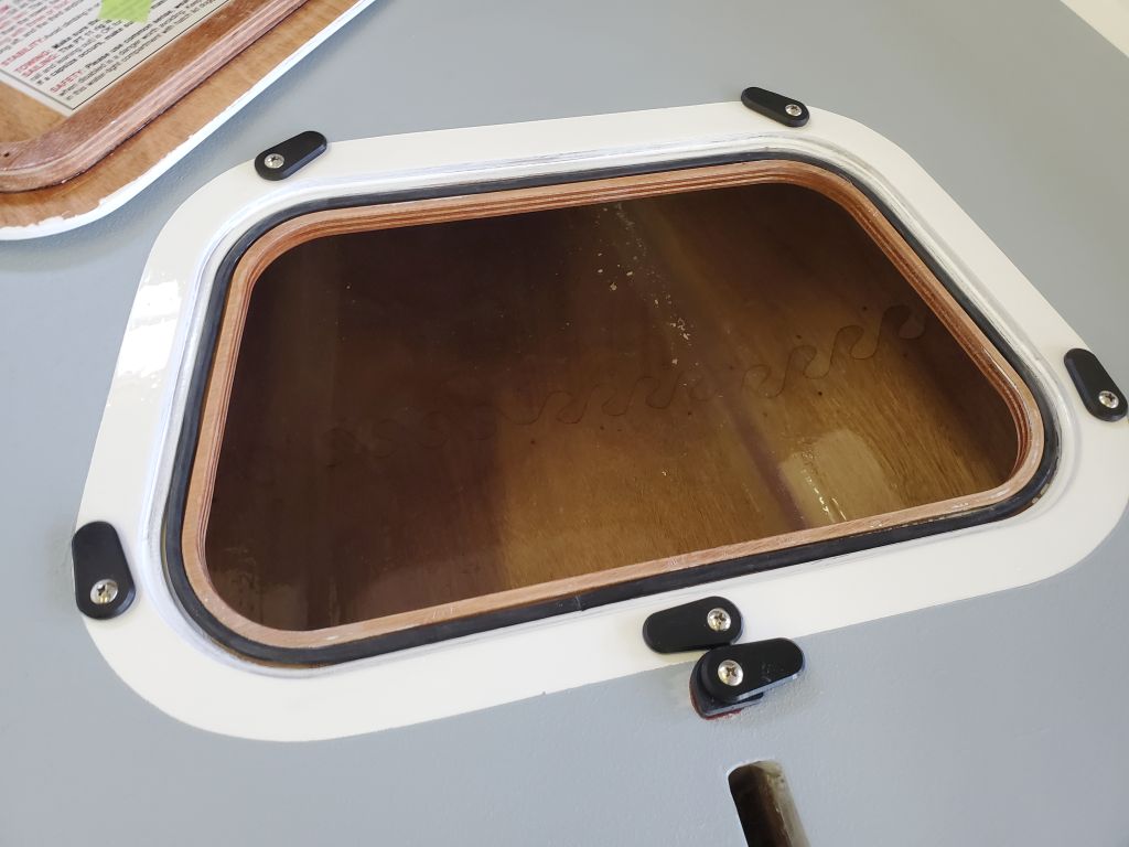
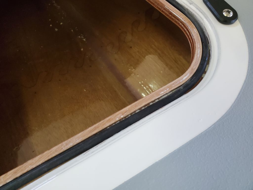
Gluing was straightforward and effective in this way. Several inches at a time, I’d lift the gasket, apply a small bead of the glue, reinstall the gasket, then dog down the hatch lid over the whole thing to hold it in place briefly while the glue cured. In practice, the curing happened quickly, and soon the gasket was in place and complete.
I worked on the small daggerboard lid concurrently, alternating gluing operations with the hatch, and before long both these gaskets were complete. The book made it sound like it would be more challenging than it turned out to be.
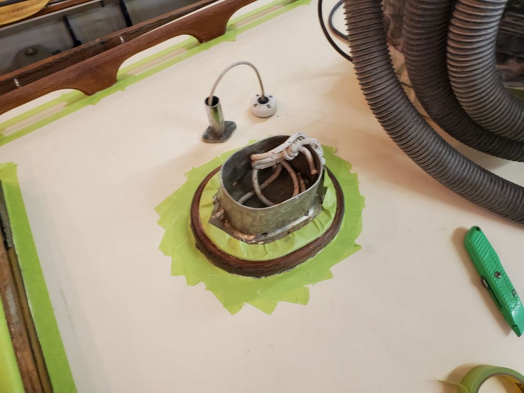
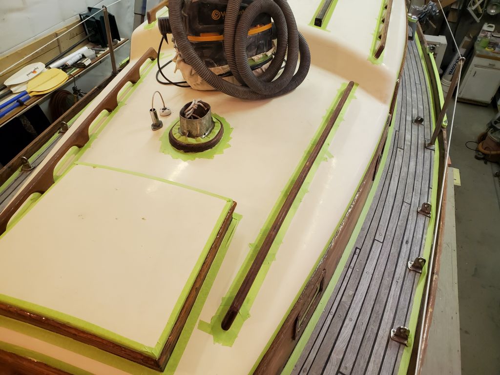
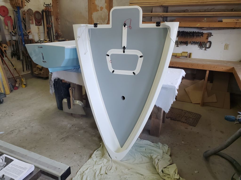
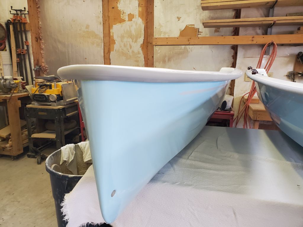
Next, I propped the hull up on its stem so I could access the gasket notch in the bulkhead with it held horizontal for weighting purposes. (In reality, at least with the glue I used, I probably could have easily glued this gasket with the hull in its normal orientation.) I used a scrap of plywood and a lead weight over each section to hold it while gluing, and had bits of tape ready if needed, but I never needed the tape, and the gluing process went quickly.
To help prevent the gaskets from sticking to their mating surfaces during longer periods of assembly, the book suggested a light coat of paste wax on the opposite surface–not on the gasket. So I applied some paste wax to the underside of the hatch lip, the deck around the daggerboard, and on the aft hull bulkhead opposite the gasket. This treatment is suggested periodically to ensure the gaskets avoid the tendency to stick.
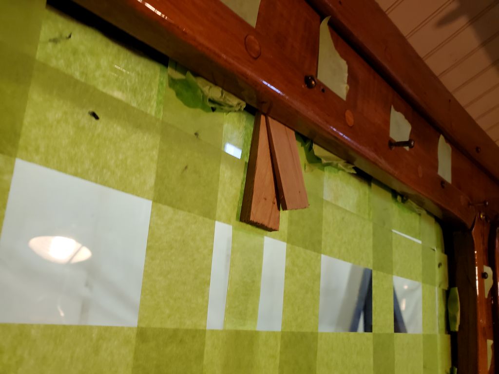
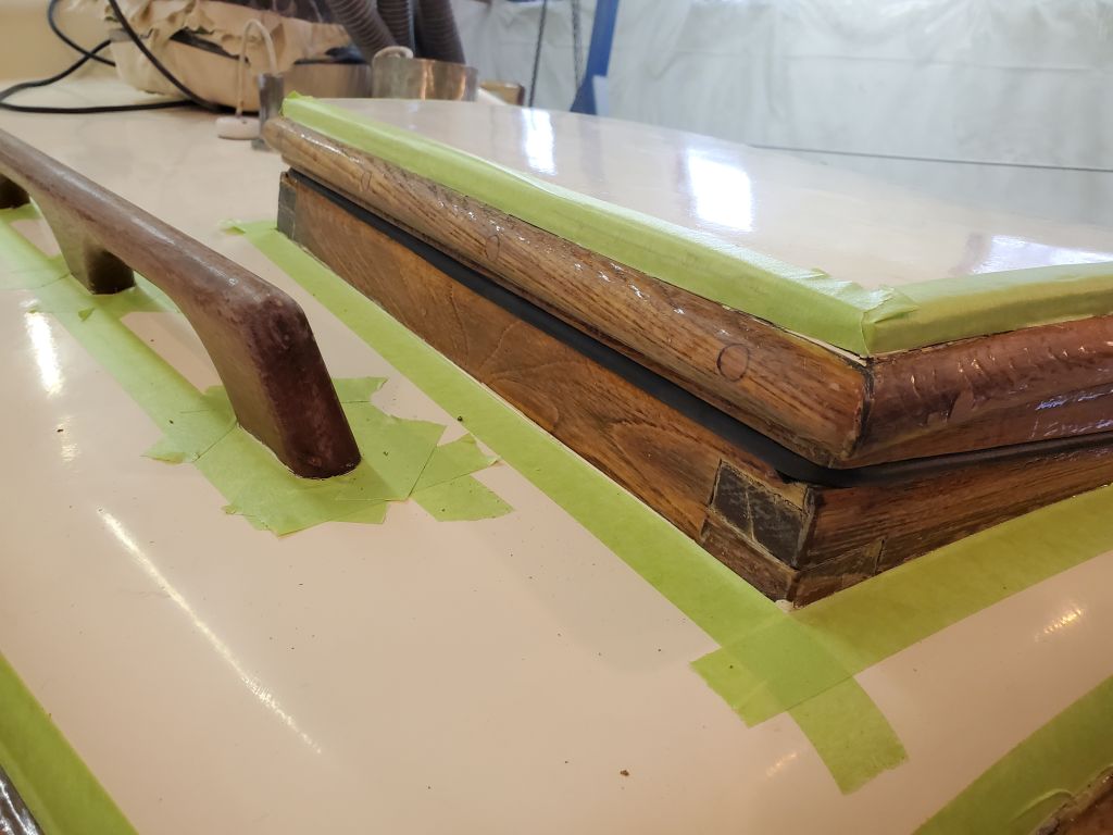
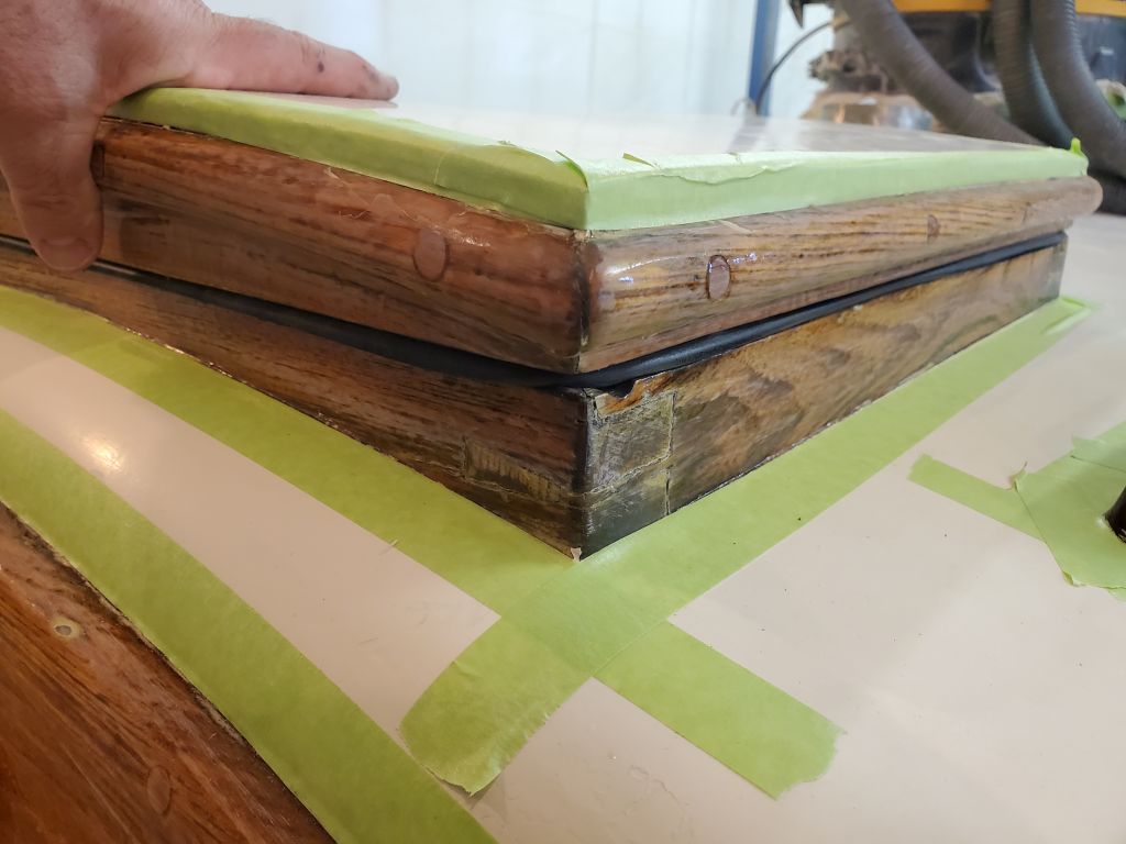
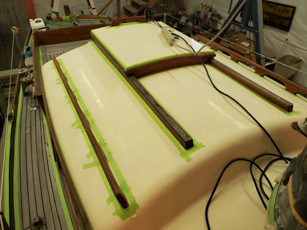
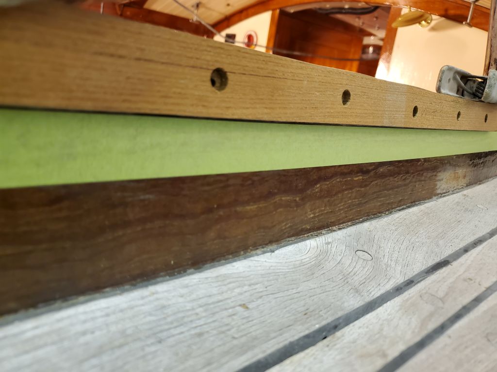
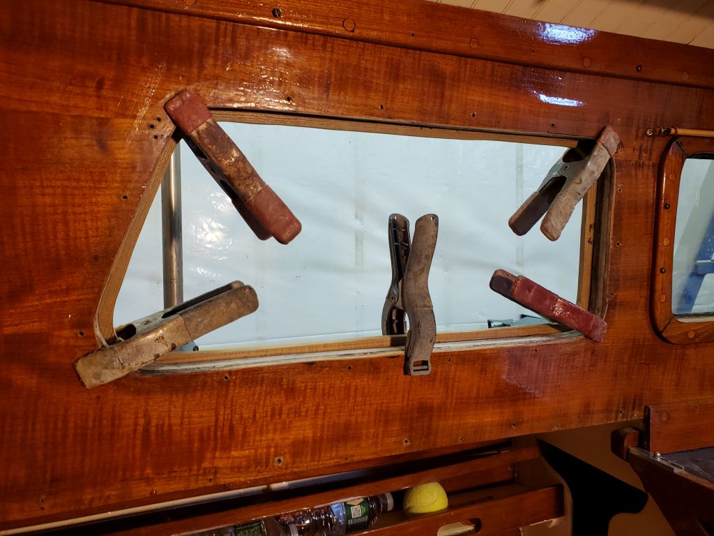
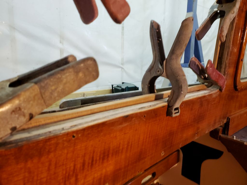
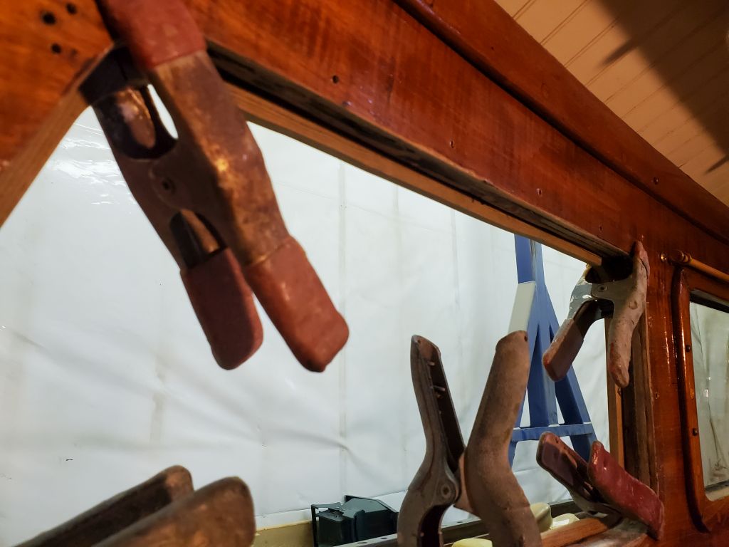
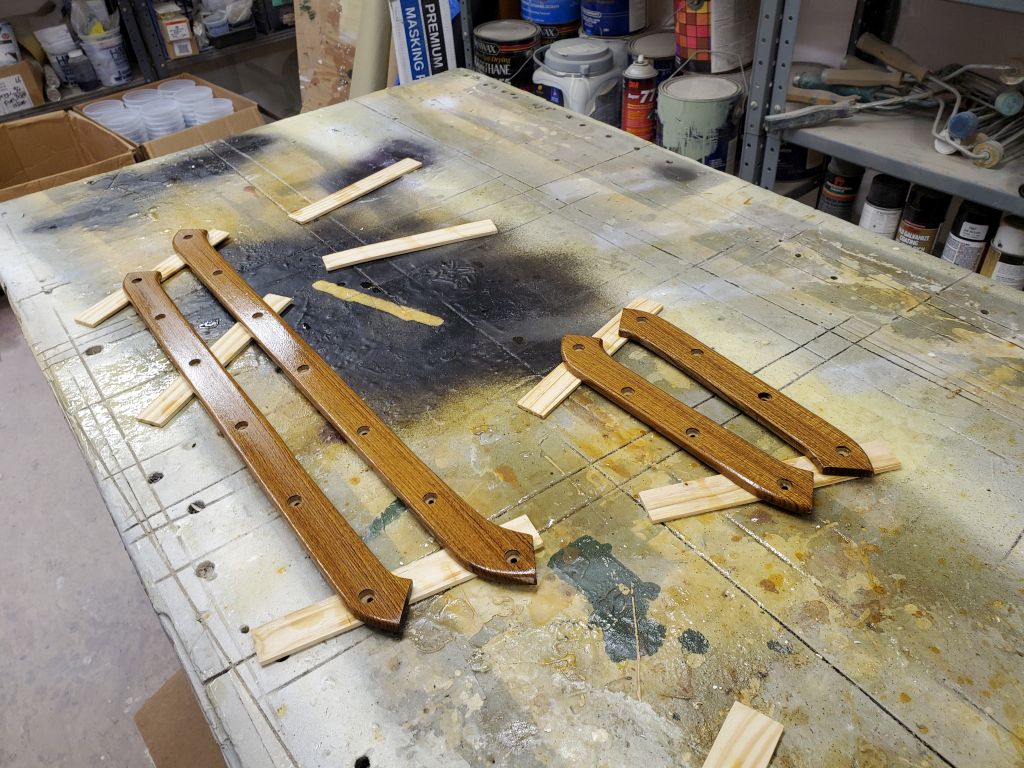
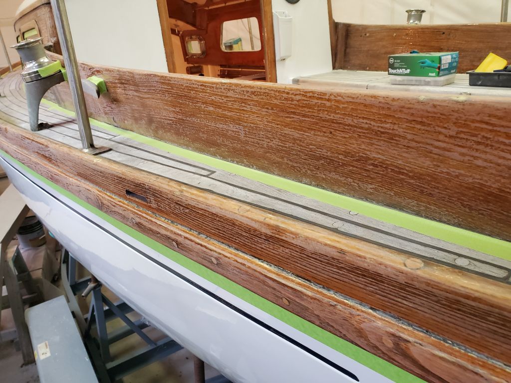
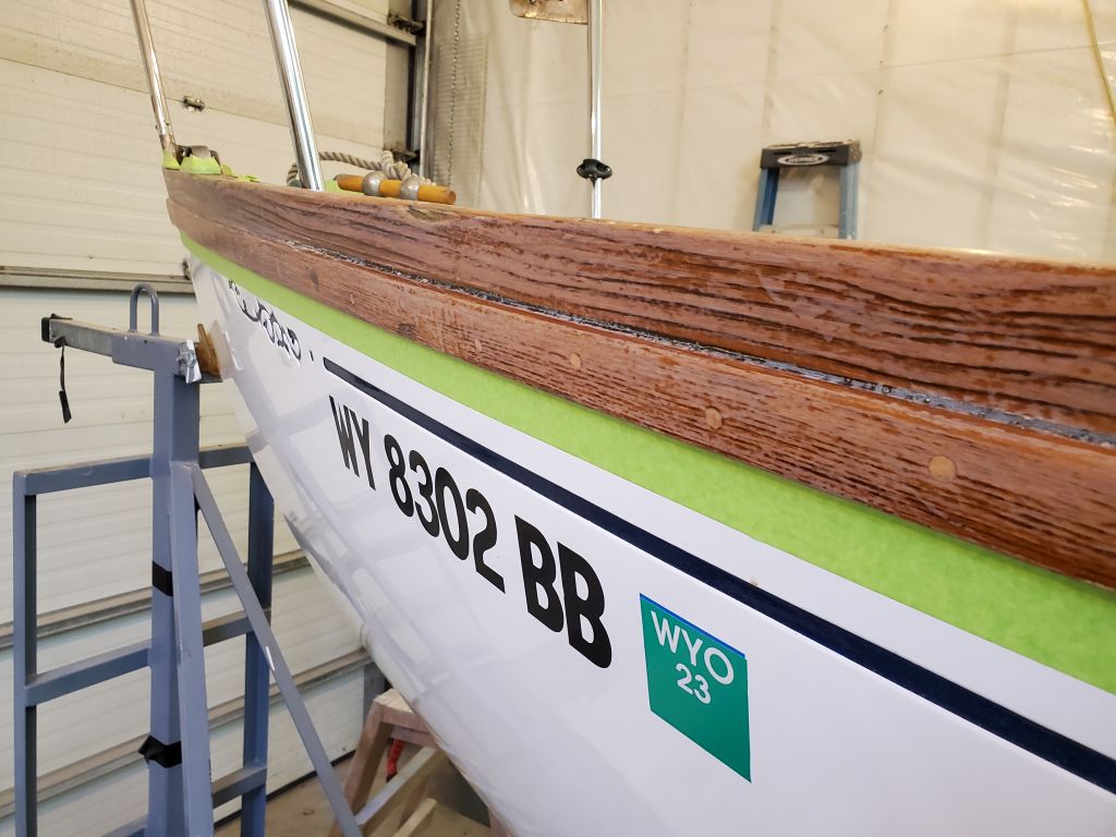
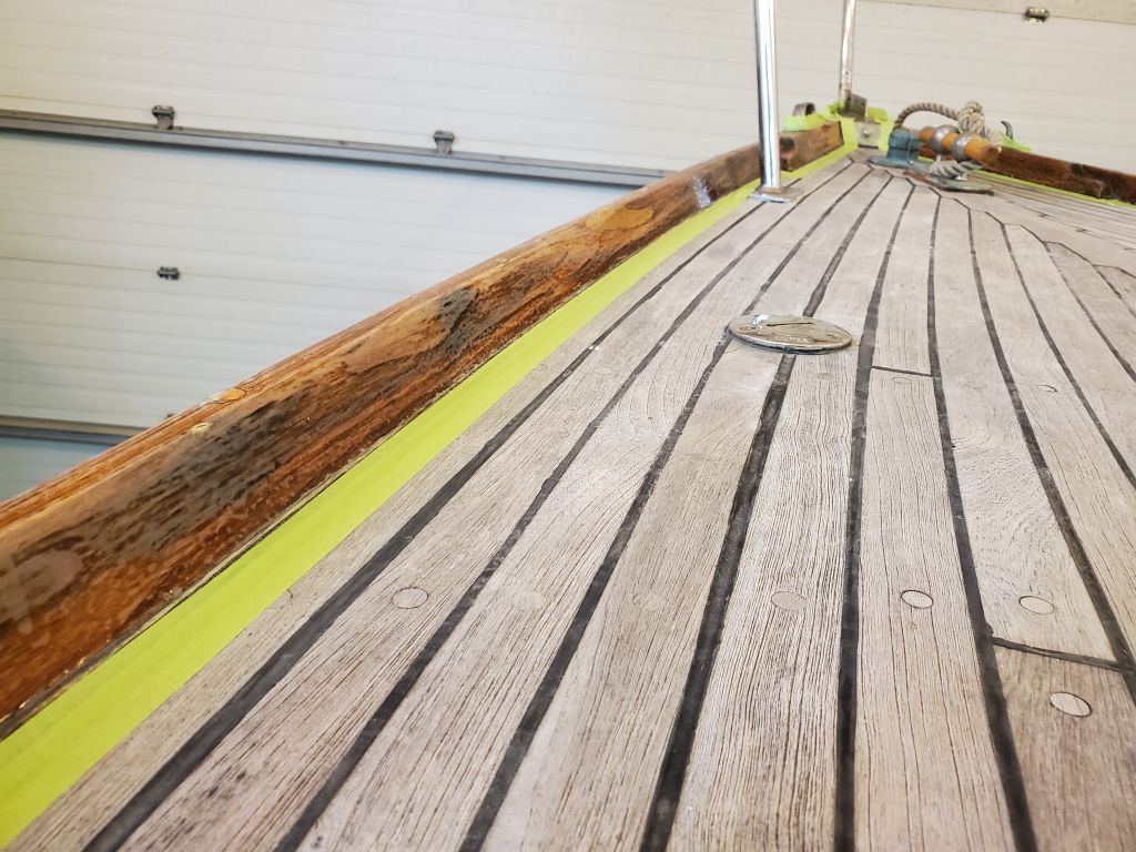
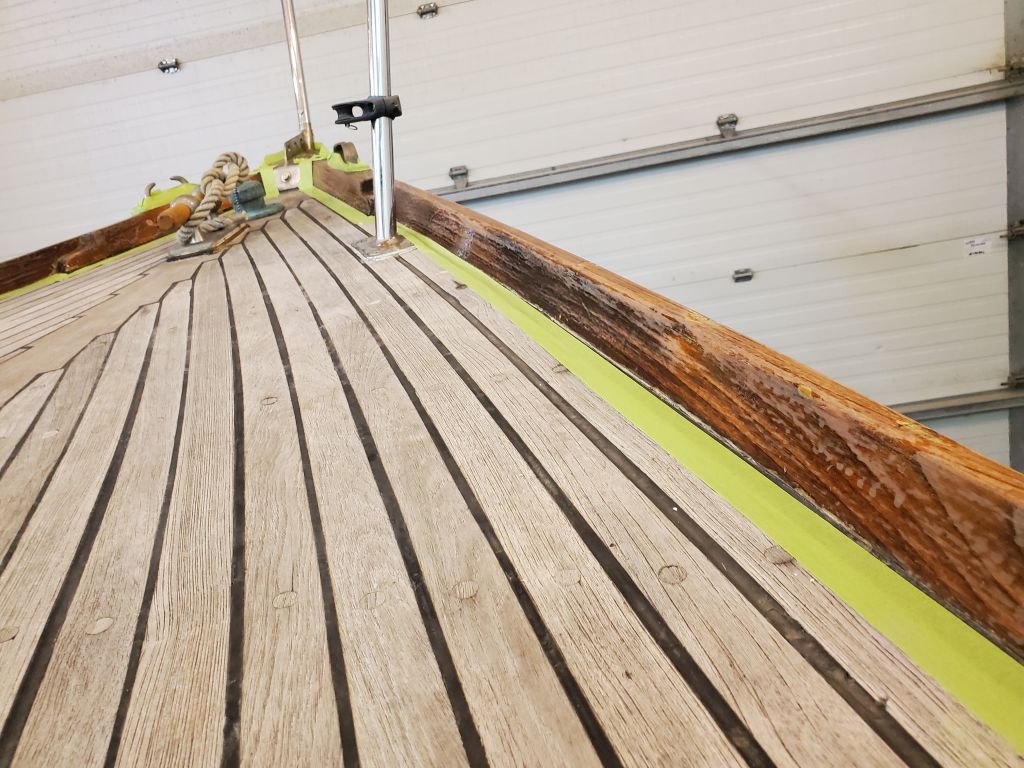
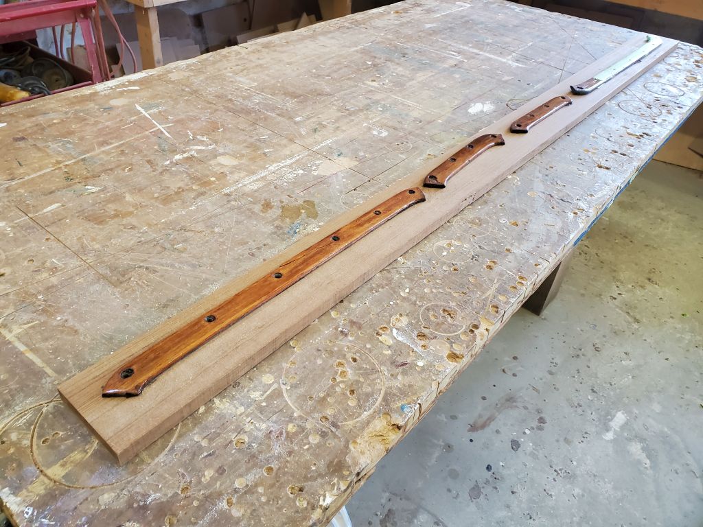
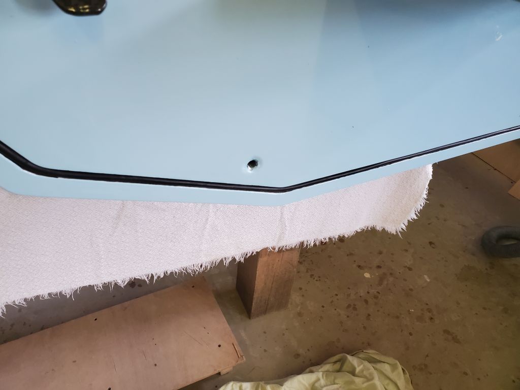
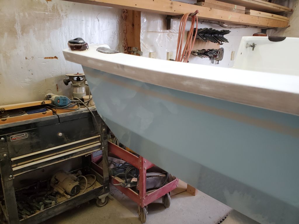
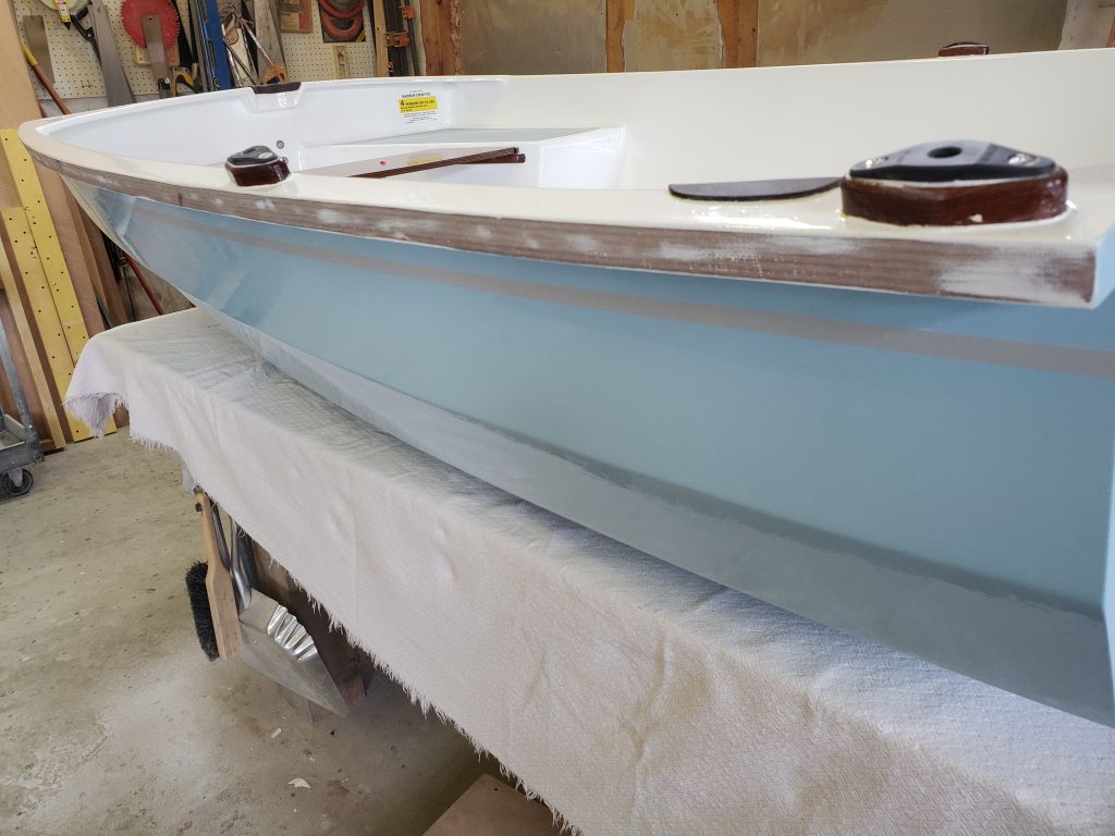
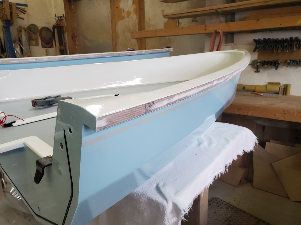
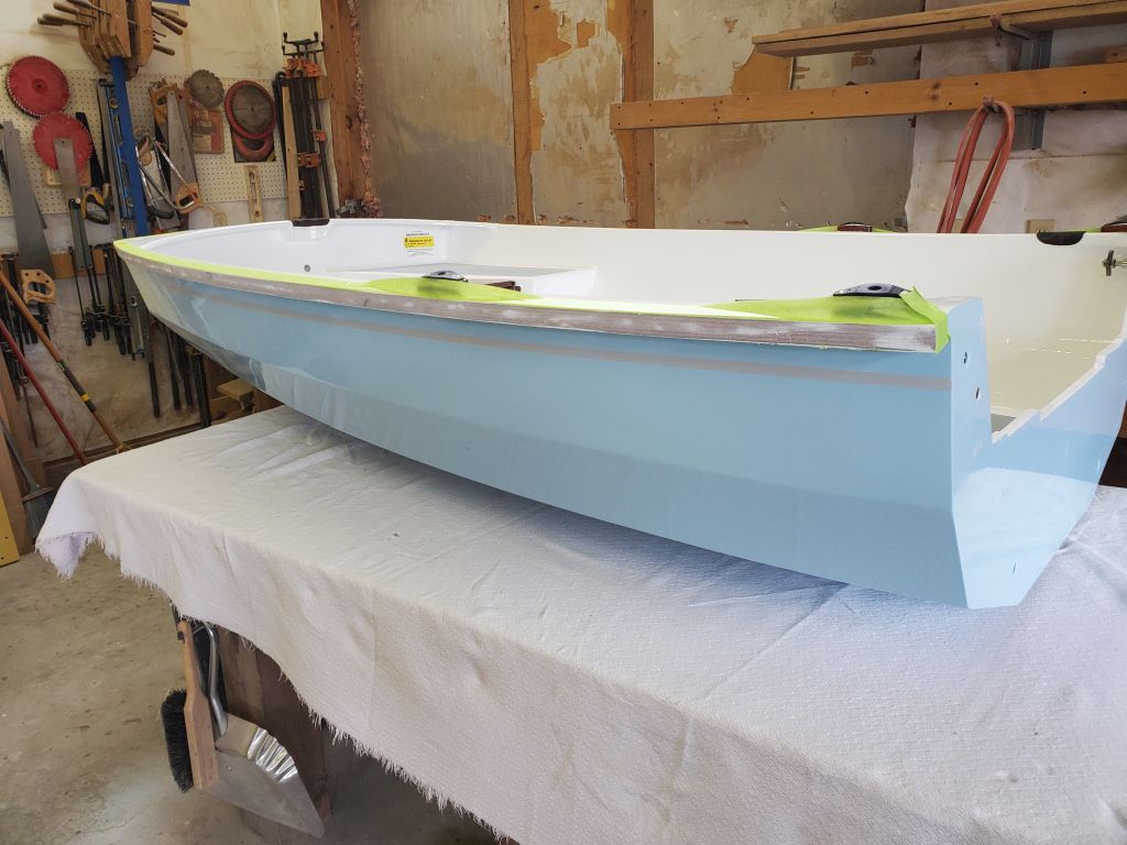
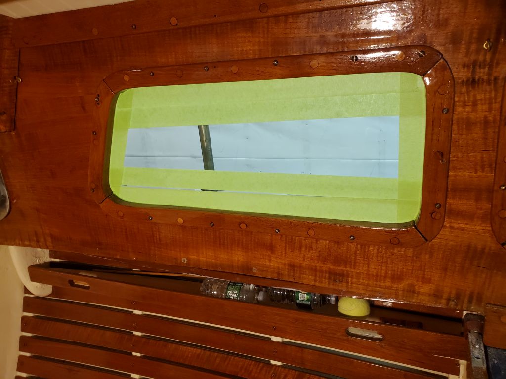
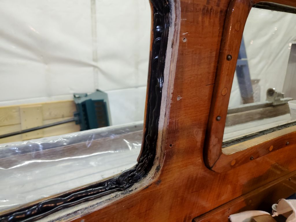
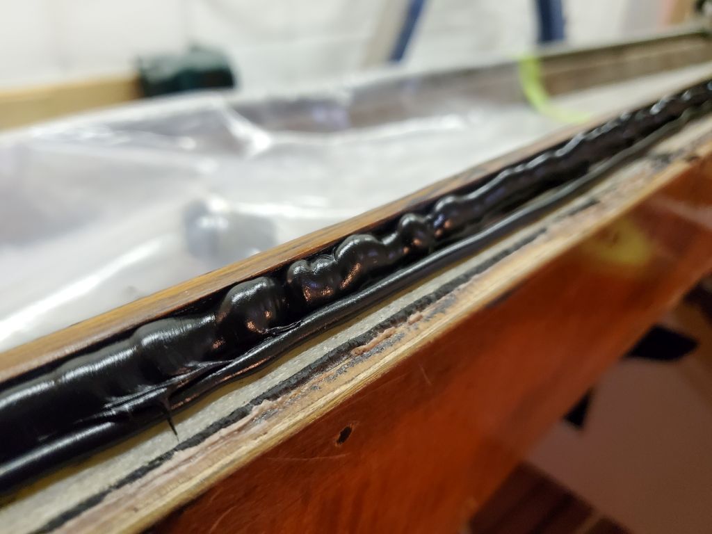
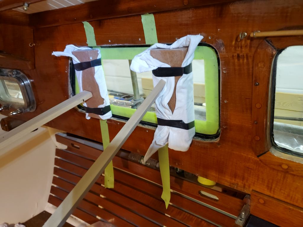
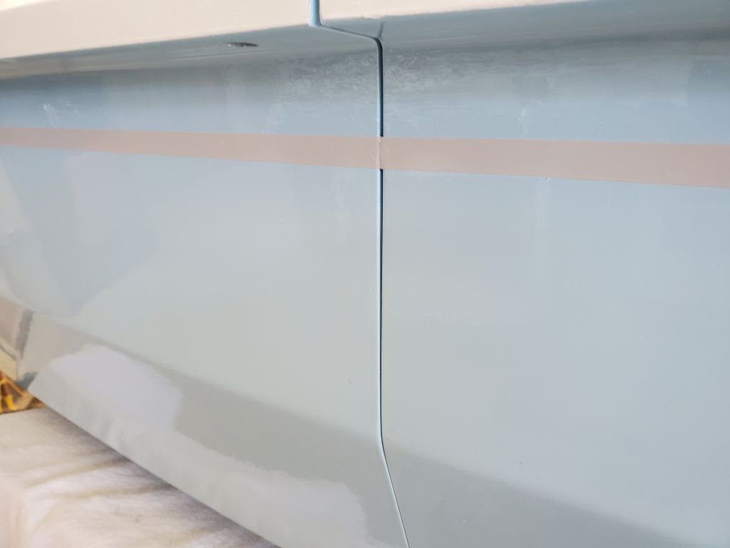
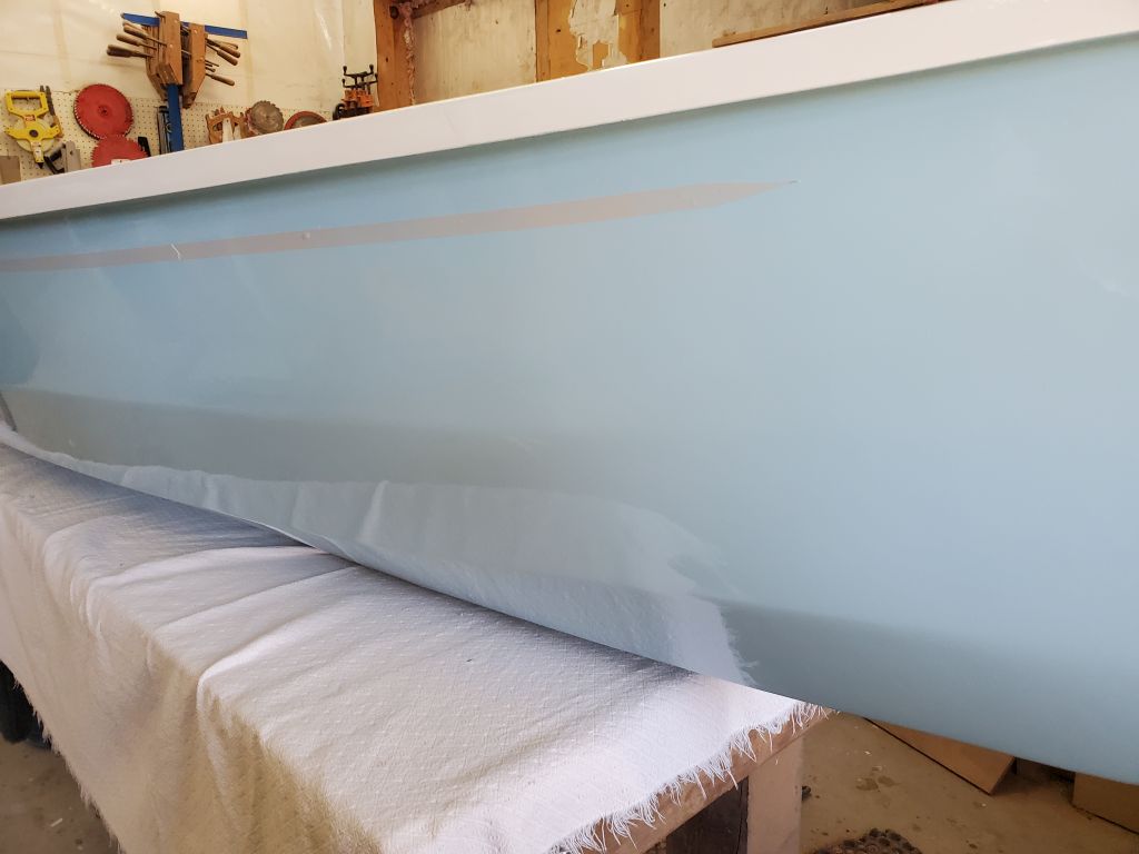
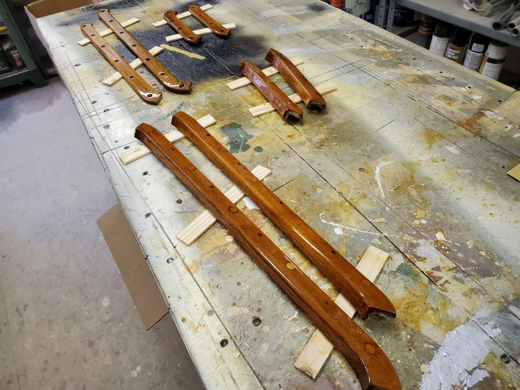
Now I could move on to the final task remaining in this build: installing the rubrail. From the start, I’d not looked forward to this, and again the book seemed to suggest it would be profoundly difficult. (The book does this a lot, actually.) To begin, I prepared the outside faces of the gunwales on both halves of the boat with a thorough sanding to remove the bulk of the paint (hindsight note for another time: it would have been simpler not to paint the gunwale faces). I sanded enough to ensure a good bond with the glue required on the rubrail, but not so much as to worry about sanding through the fiberglass on the gunwales.
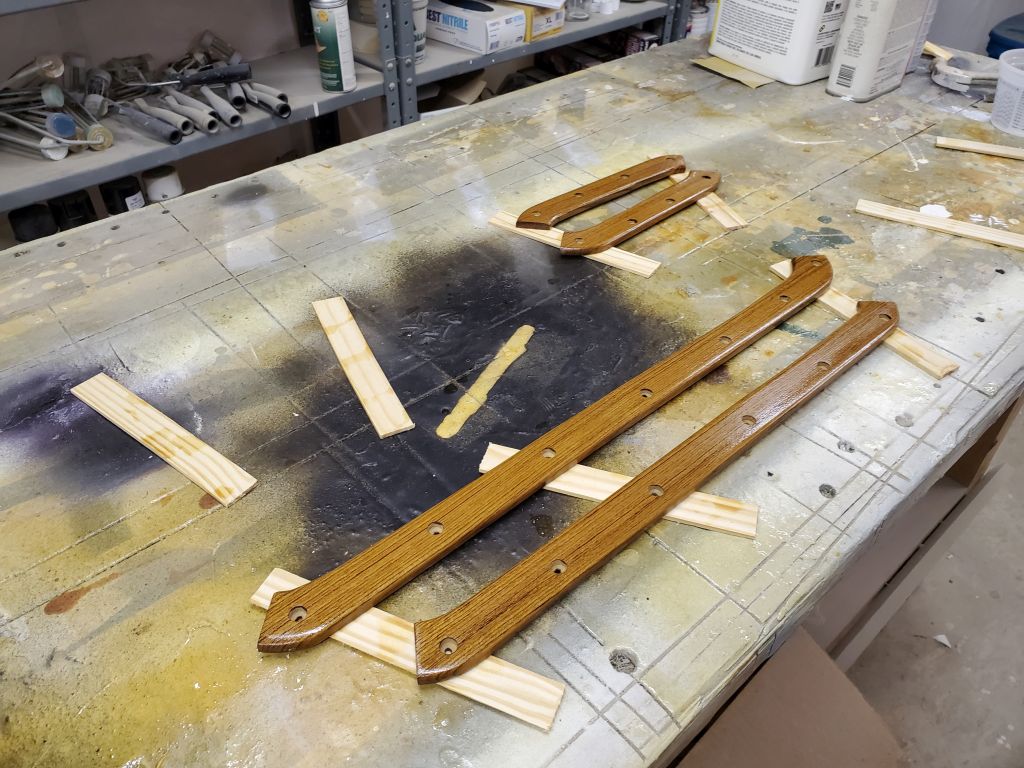
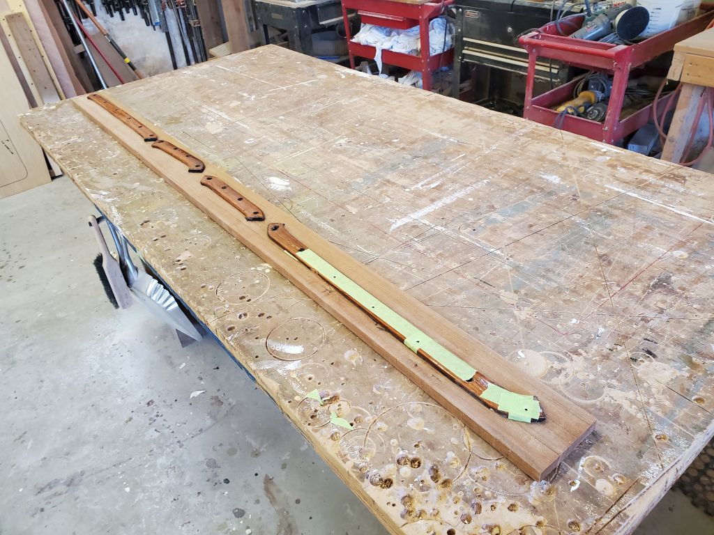
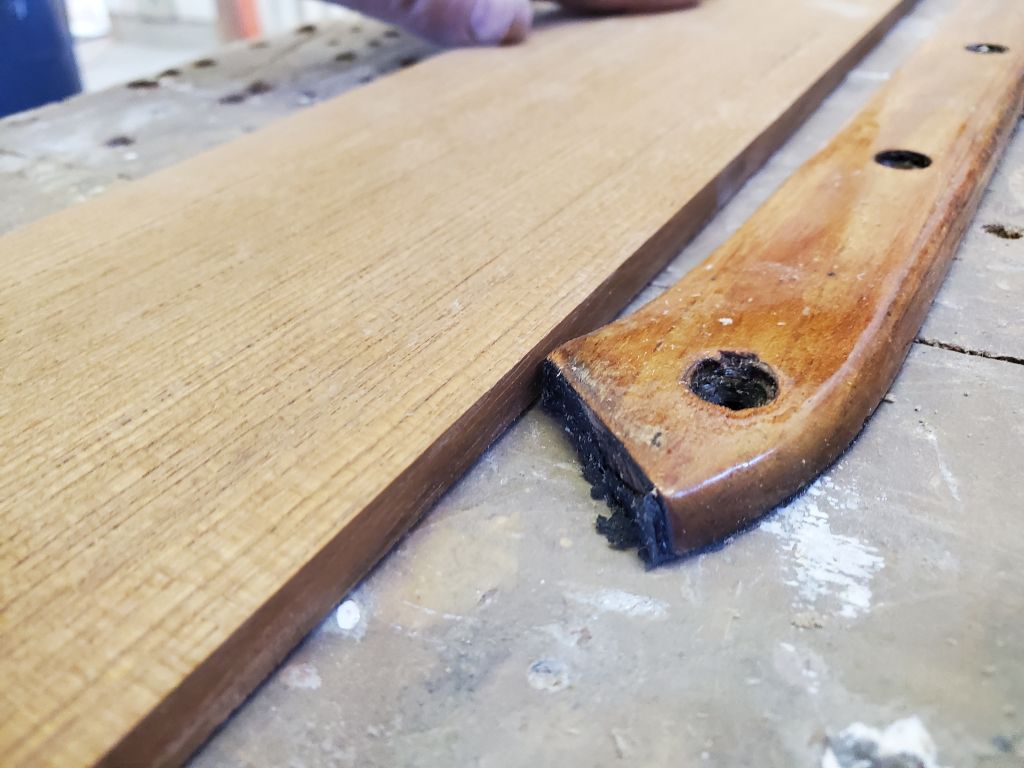
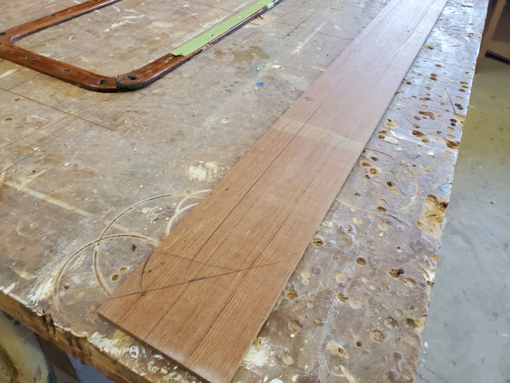
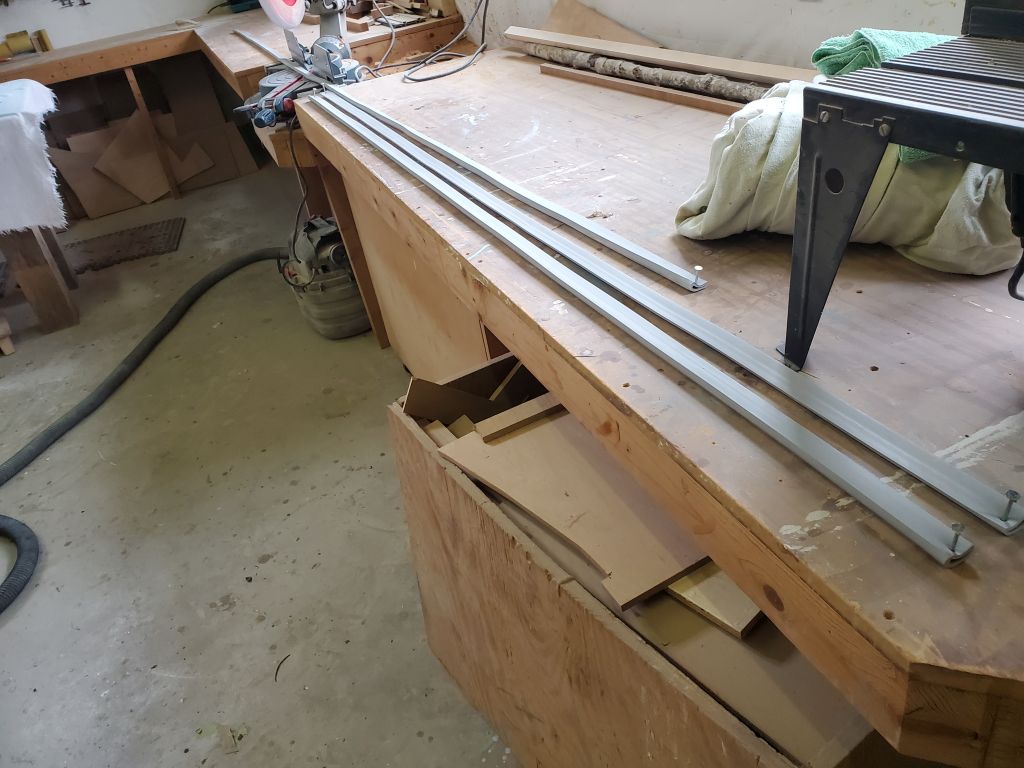
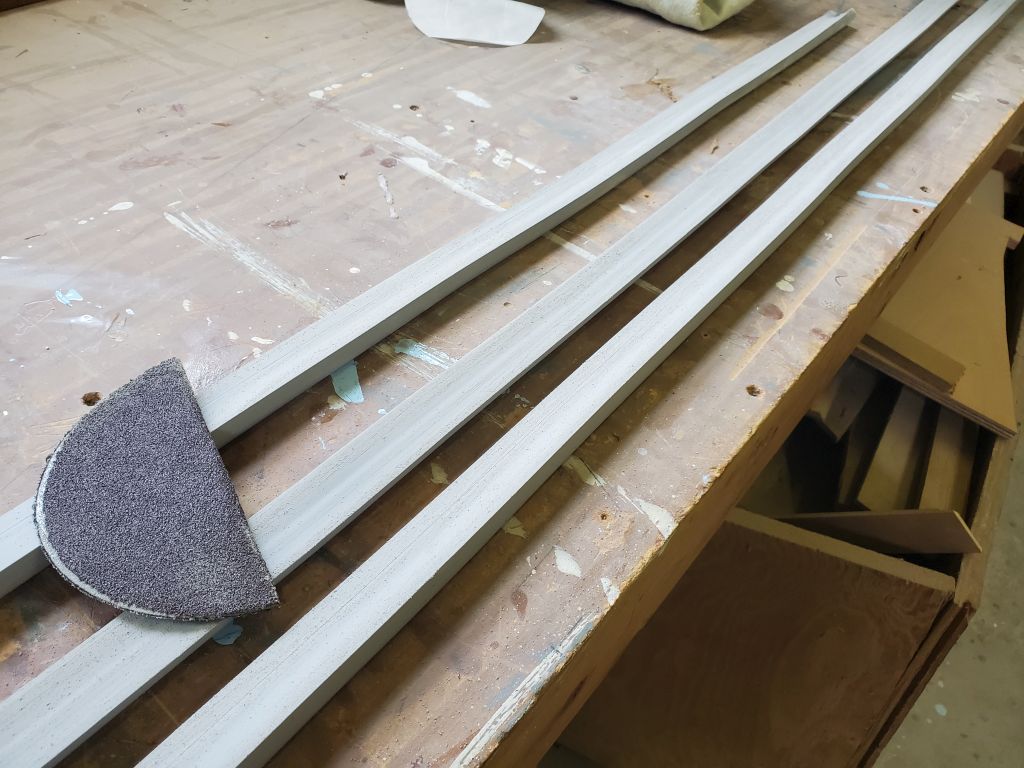
The vinyl rubrail came in three pieces: two shorter pieces for the aft hull, and one longer piece for the bow–here it would wrap around the stem and do both sides in one section. I nailed these to my bench with the mating surfaces facing up; this held the strips taut so that I could sand the back sides with coarse sandpaper (and also so that later they’d be secure for applying the glue).
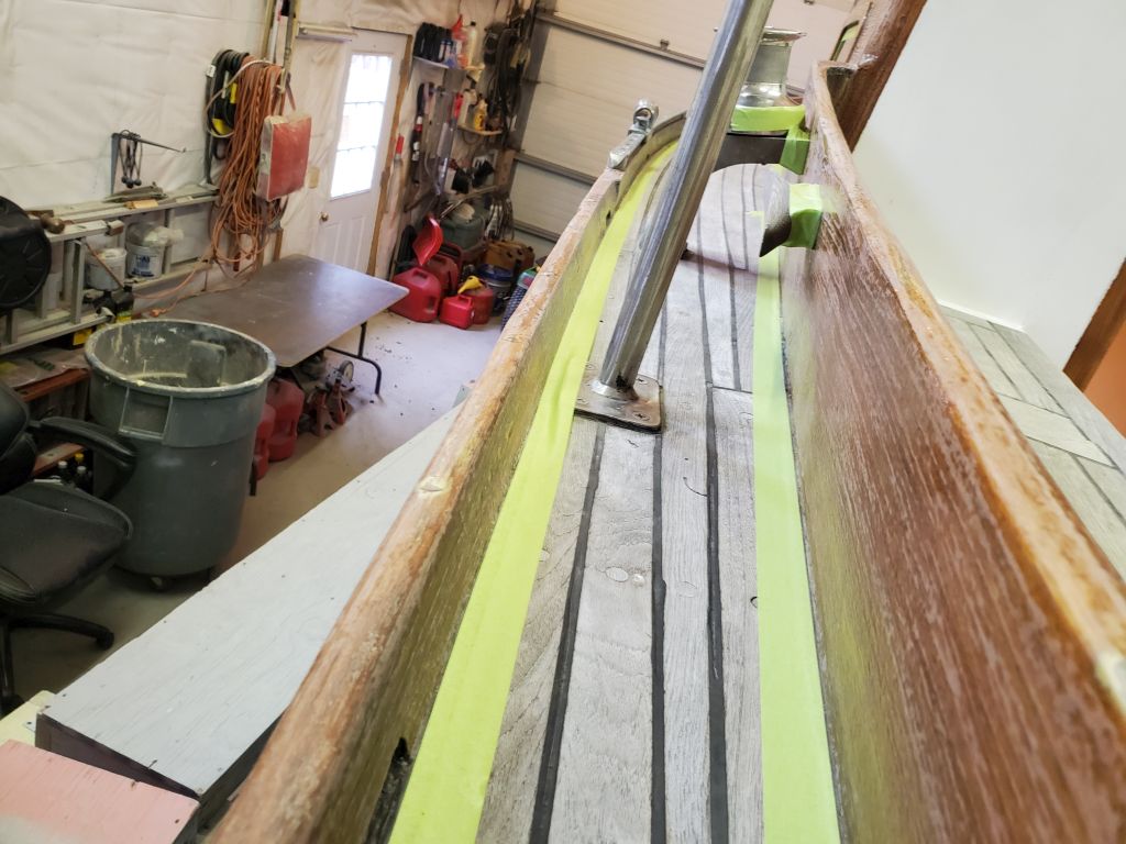
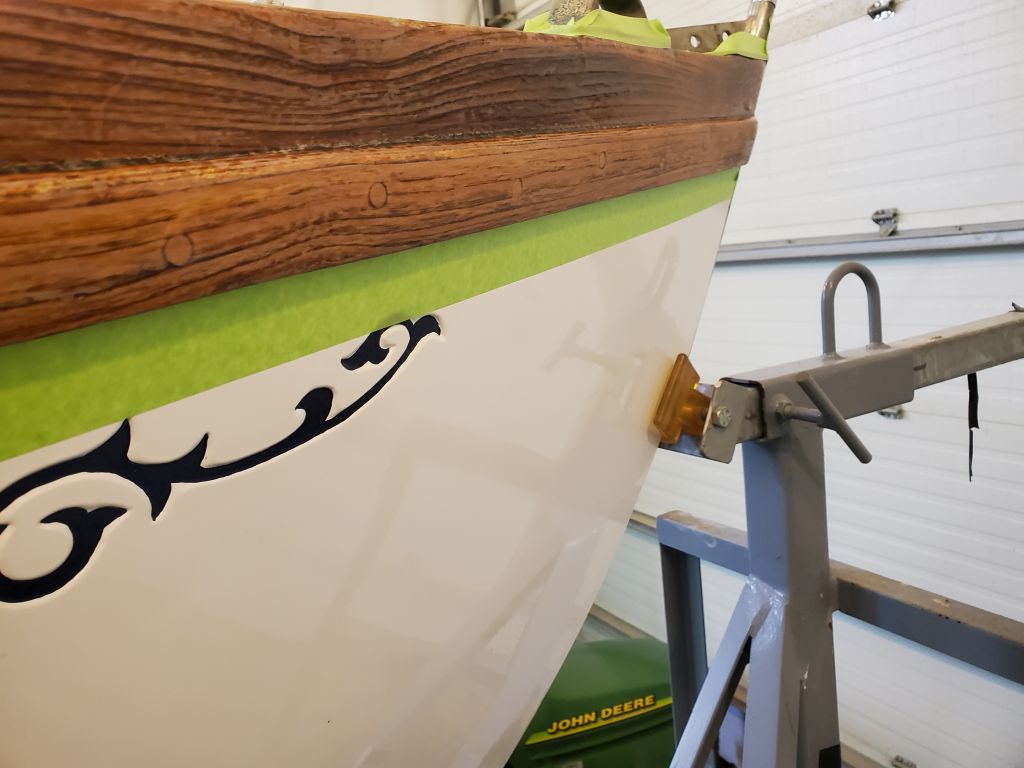
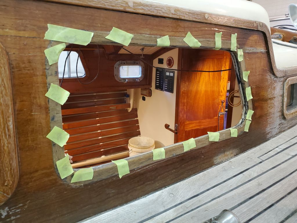
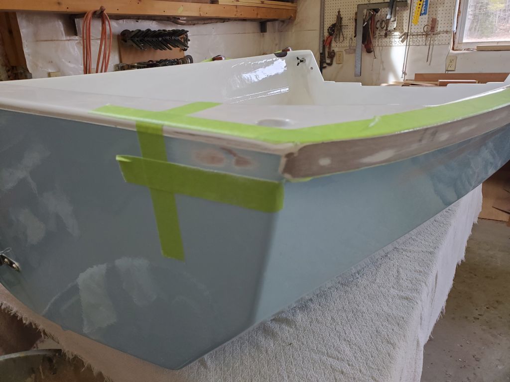
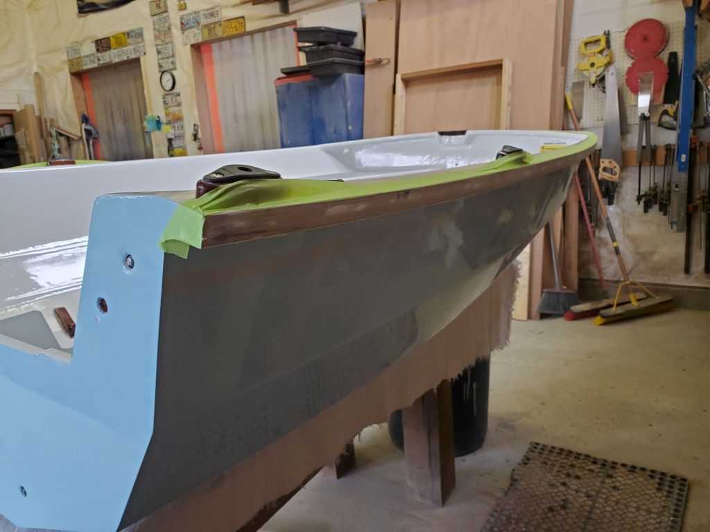
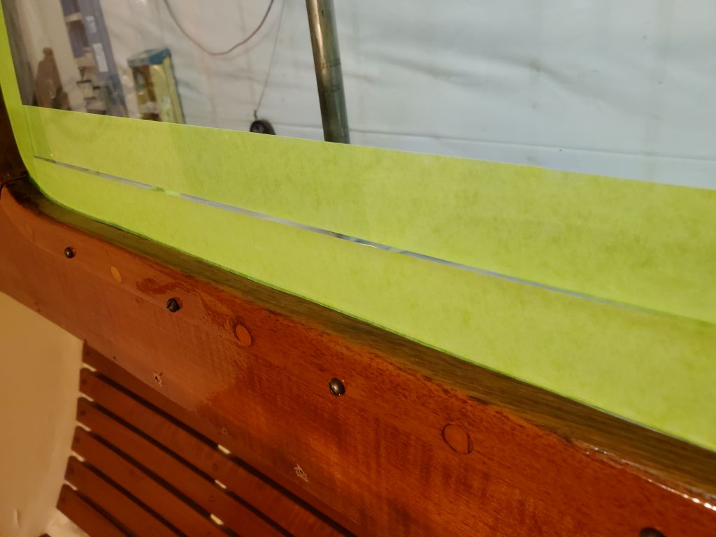
Next, I masked both sides of the gunwale–the top and bottom–and also some 4″ strips (1″ tall to match the rubrail) onto the transom face, as the gunwale would wrap onto the transom. I sanded the transom areas, as well as the rounded part of the stem, once I’d done the masking.
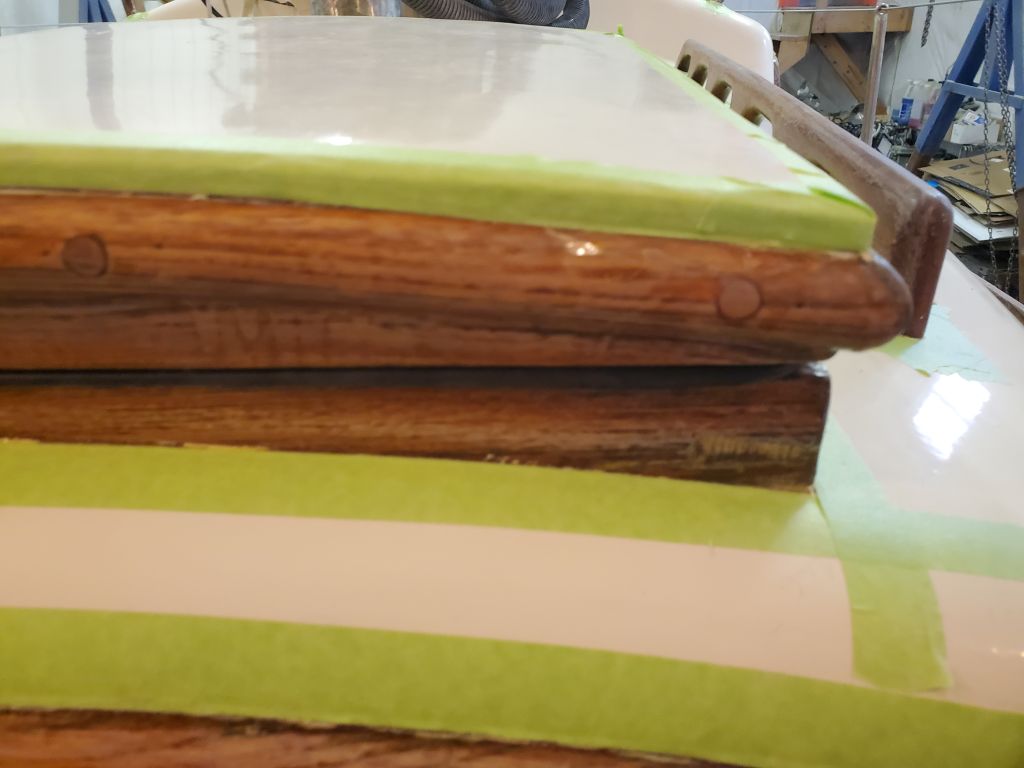
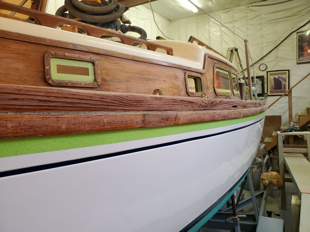
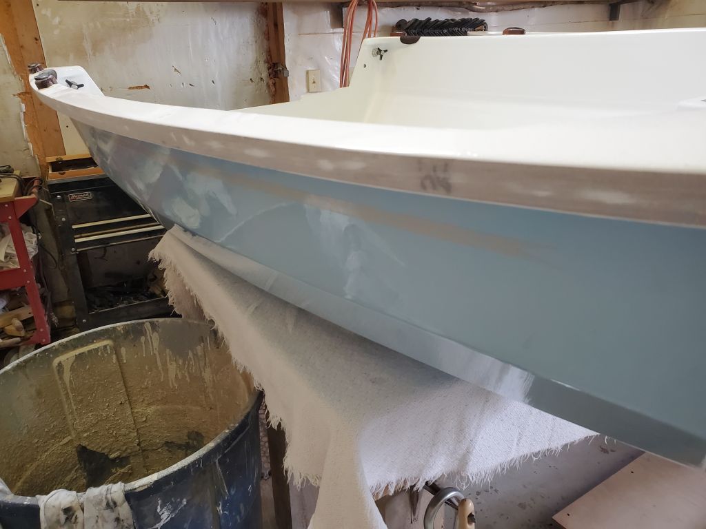
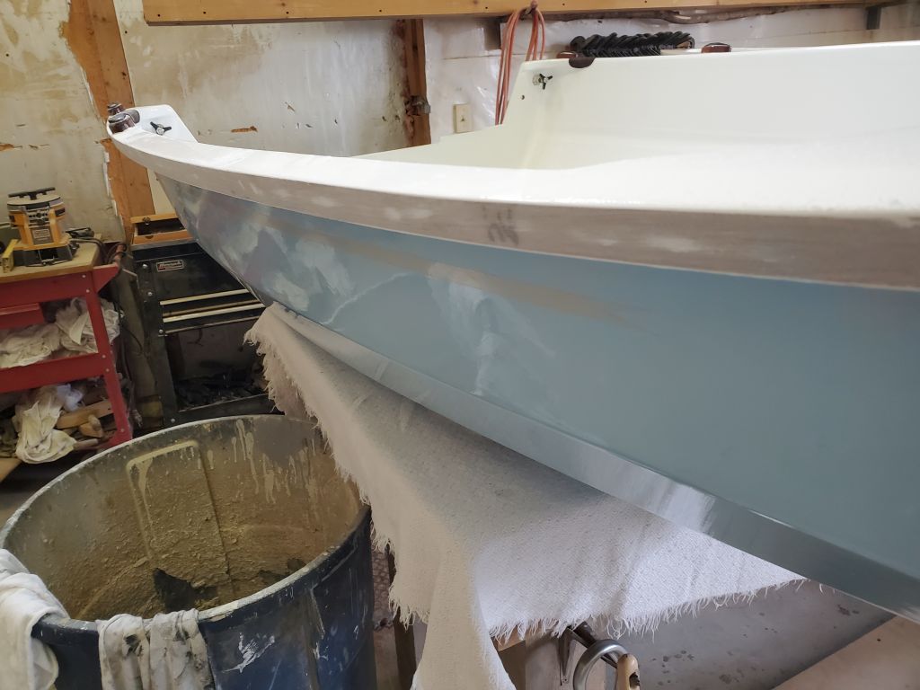
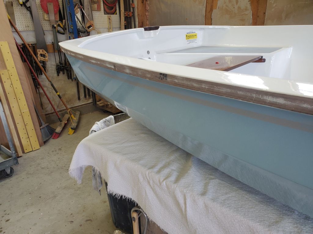
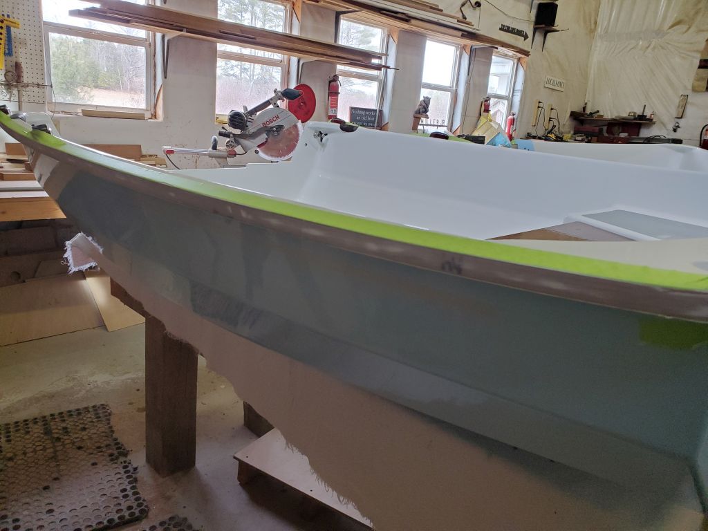
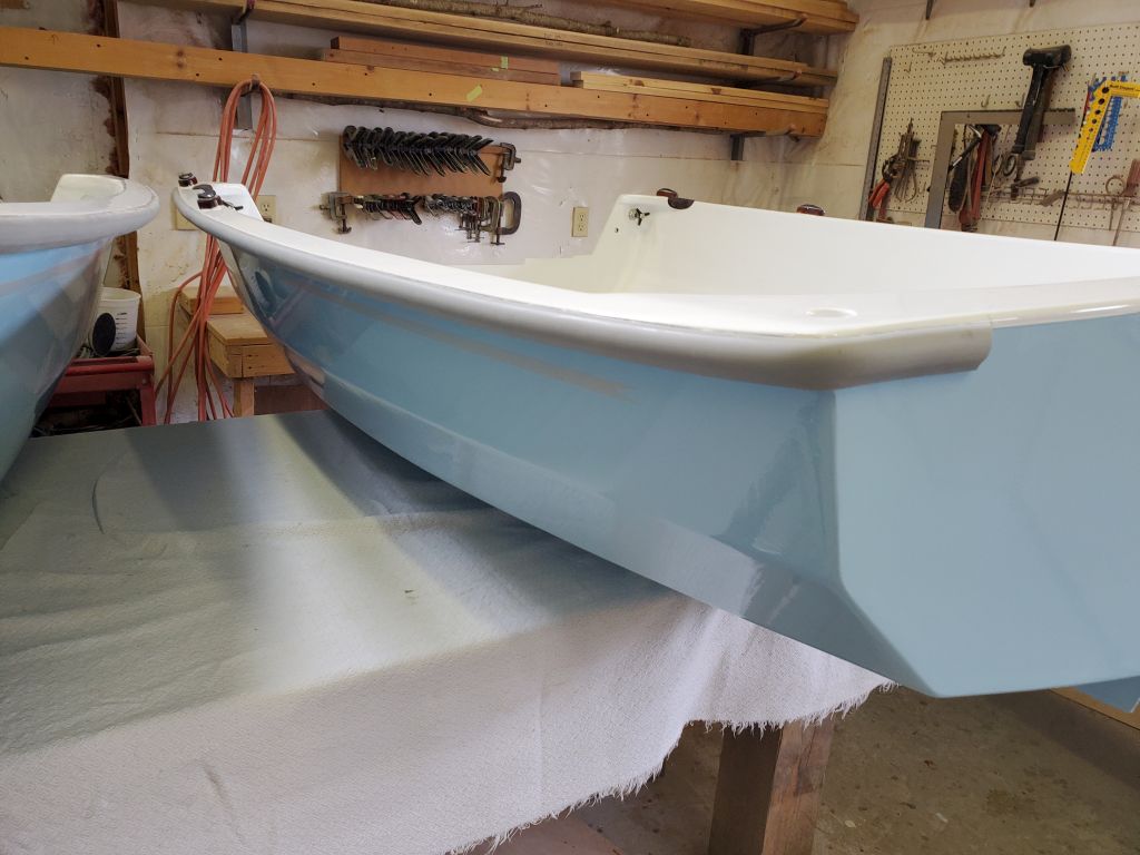
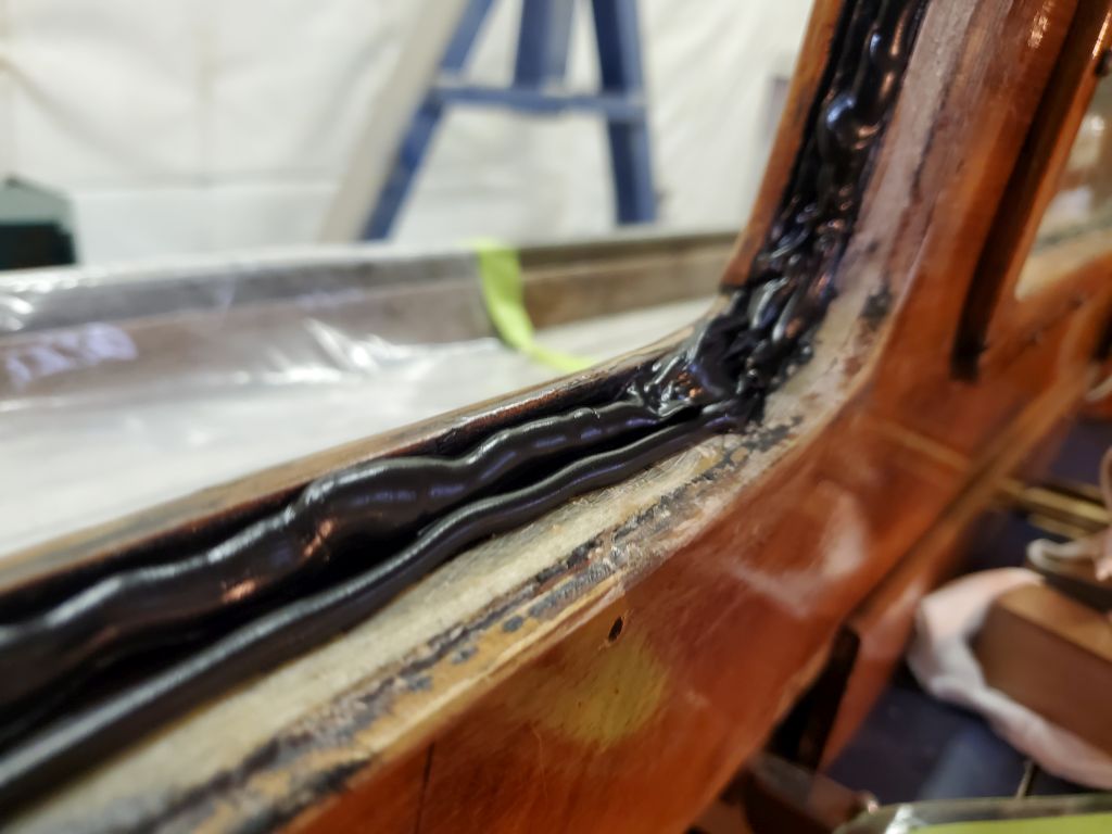
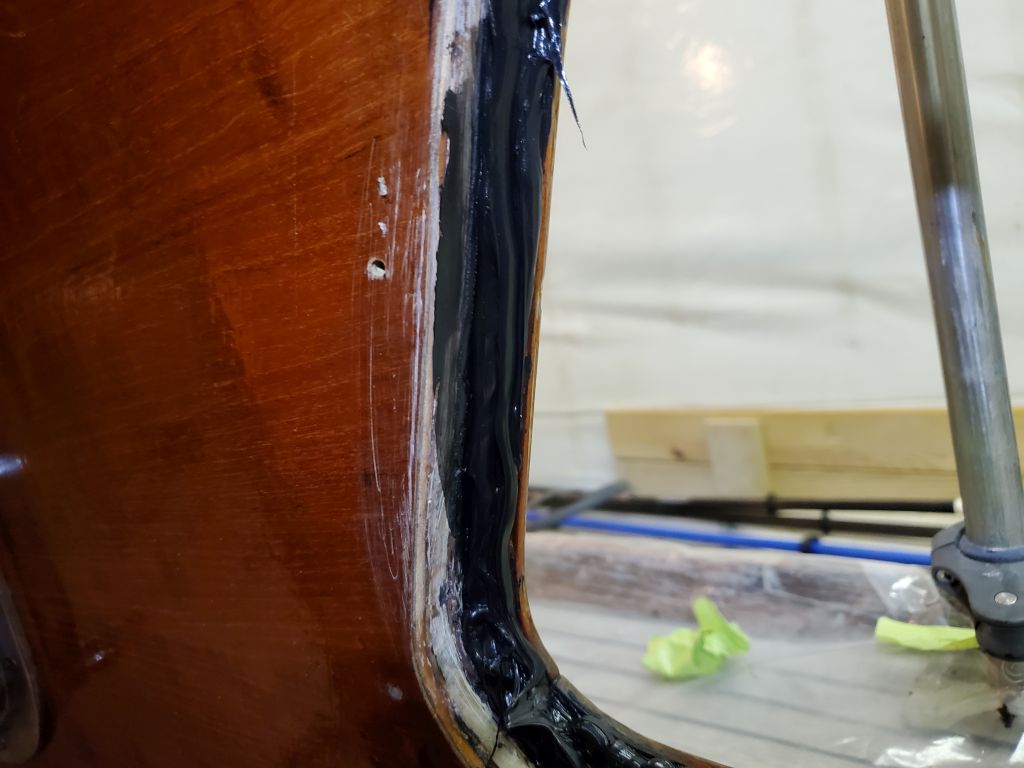
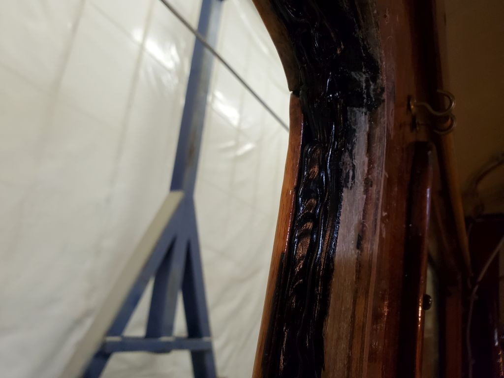
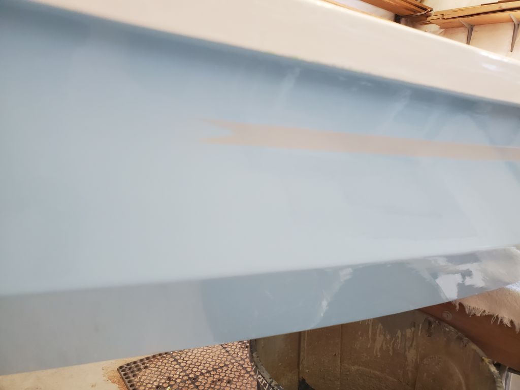
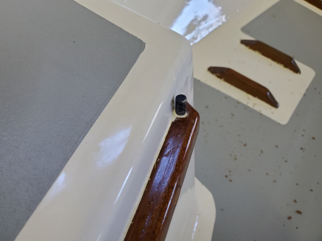
The rubrail was to be installed with hypalon glue, and now I mixed the glue according to its instructions, then coated all the gunwales and rubrail pieces with one coat. After 30 minutes, the first coat was ready for next steps, and, one section at a time, I applied a second coat of glue to boat and rubrail, then installed the rubrail. This was a contact-type adhesive, so it stuck upon, well, contact. I was pleasantly surprised by how not-bad the whole installation was, as the instructions certainly were thorough in pointing out the potential difficulties and pitfalls. But in fact it went smoothly and quickly, once the prep was done; the sanding of the gunwales had taken the bulk of the time needed for this particular installation.
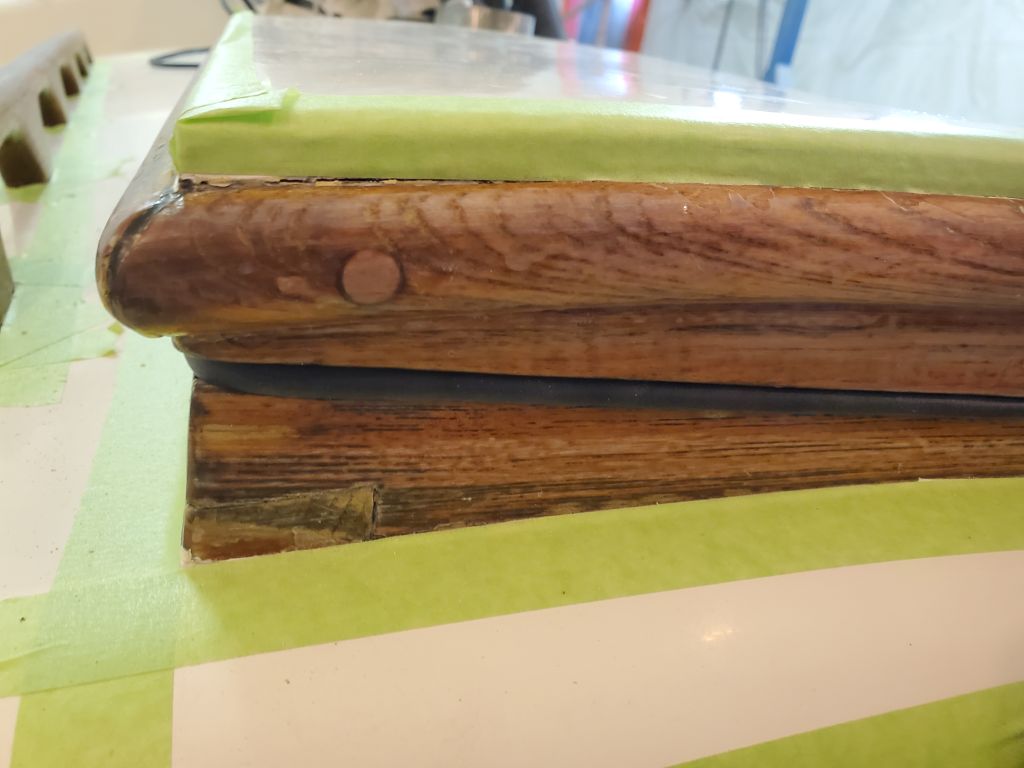
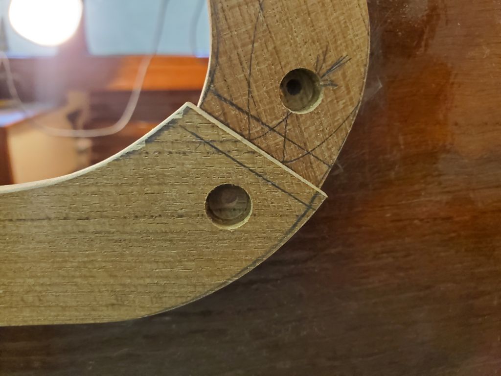
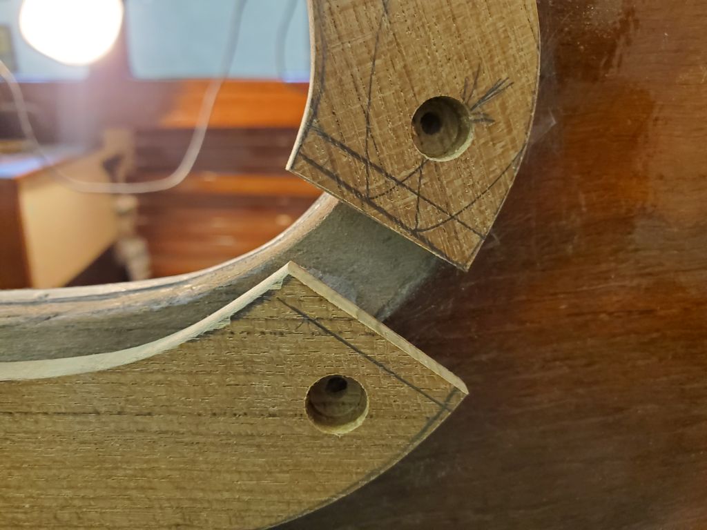
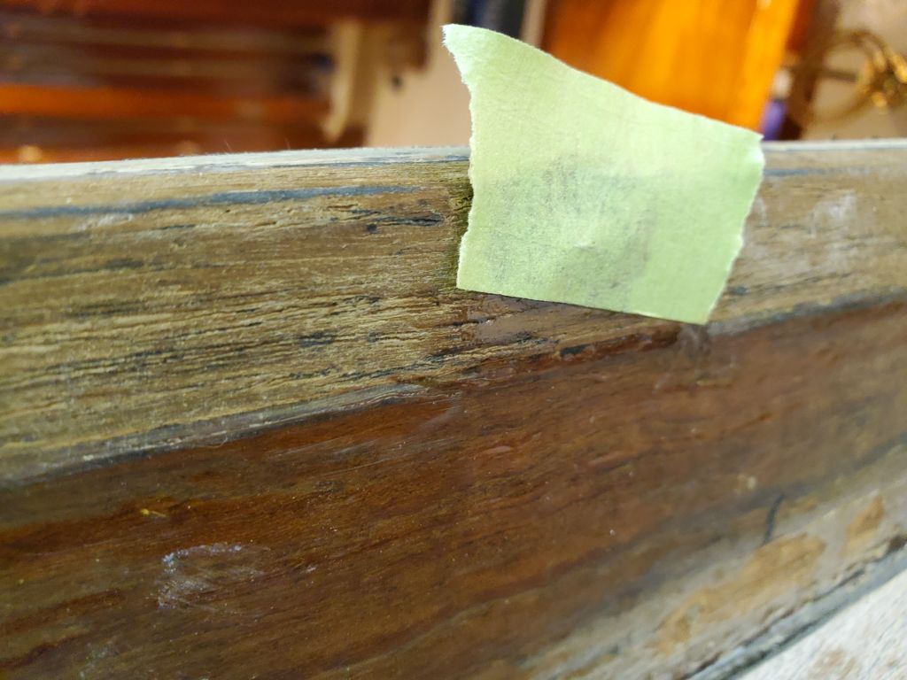
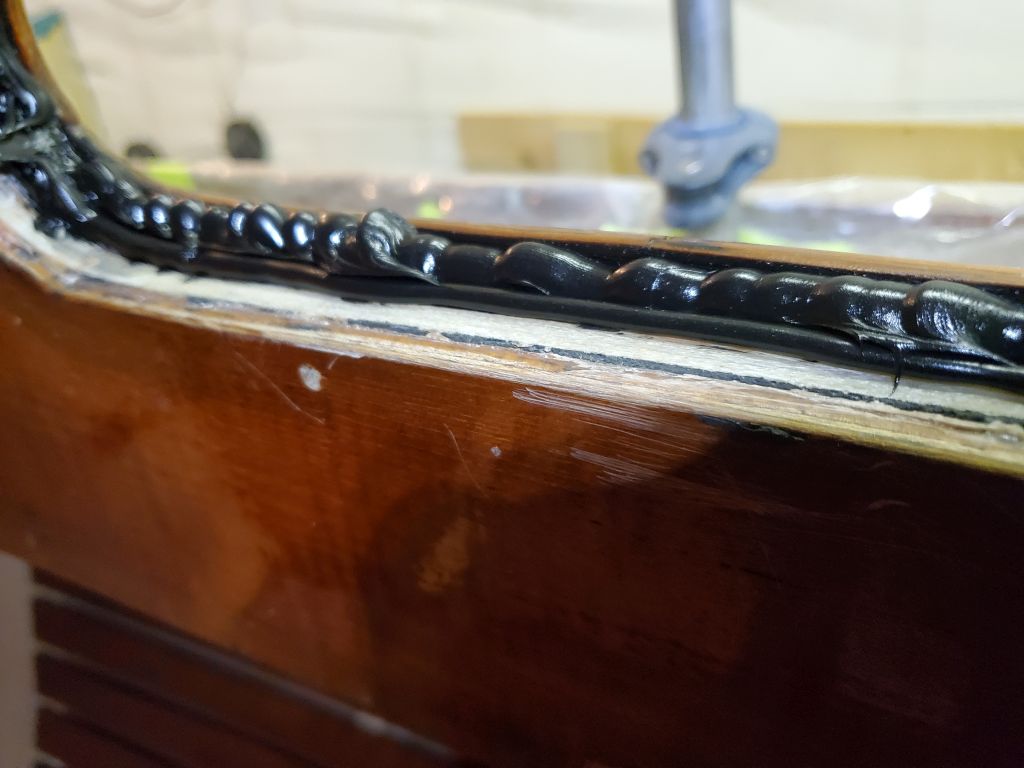
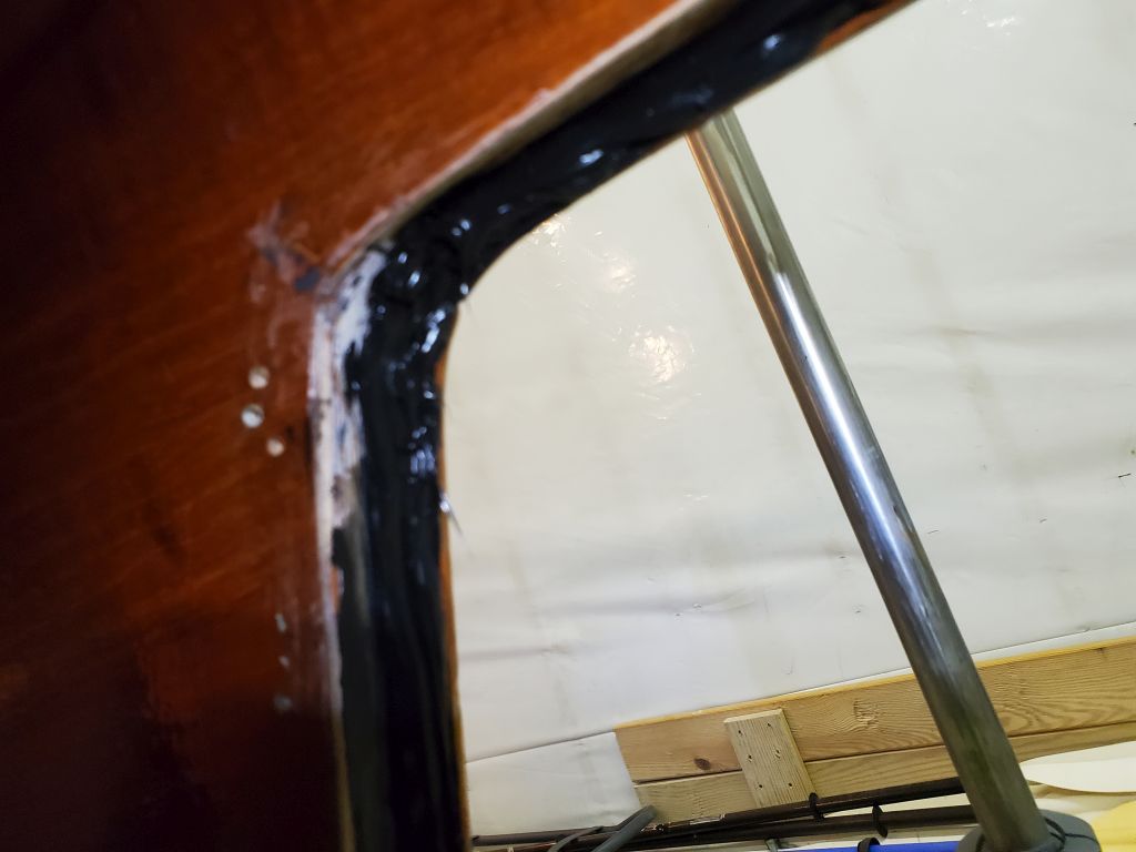
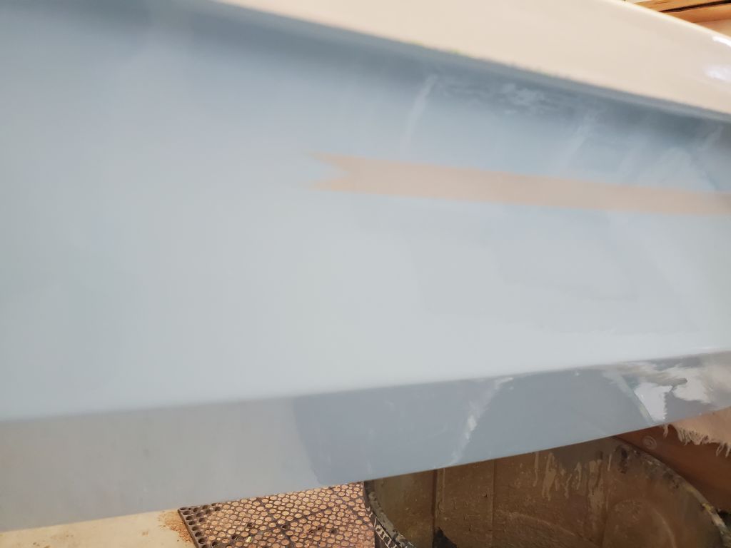
At the transom, I cut an angle into the rail where it ended at my tape marks, and cut the ends at the mating bulkheads nearly square, with the slightest angle away from the joint.
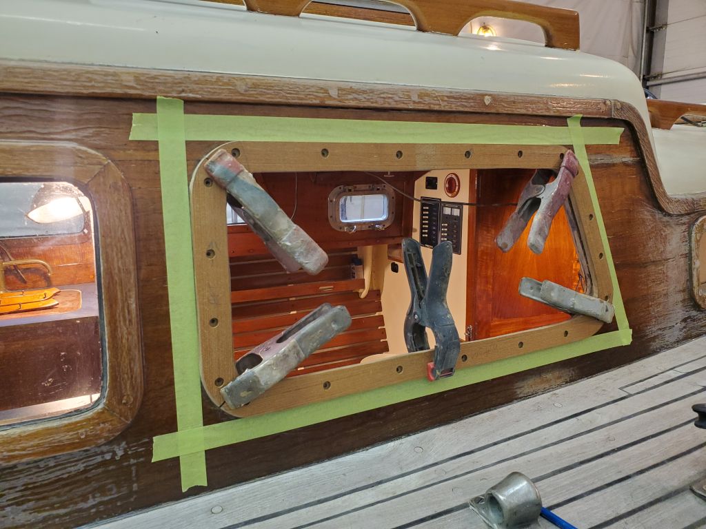
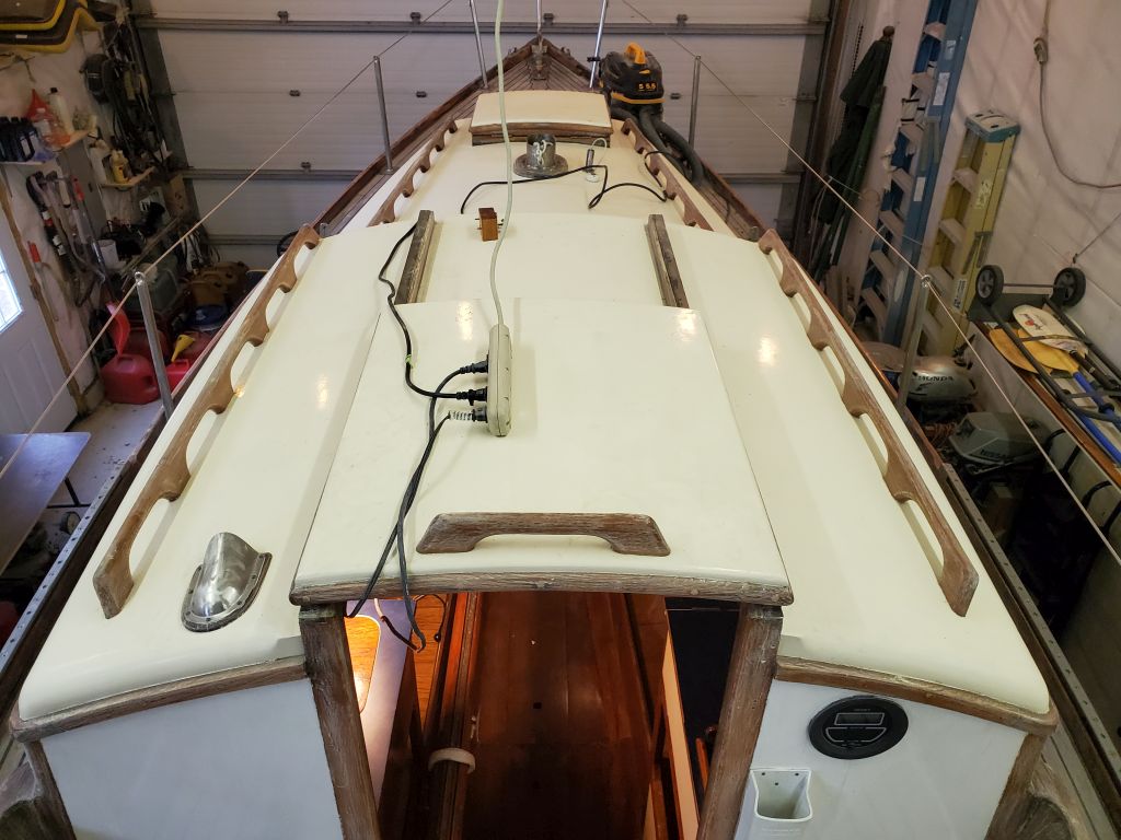
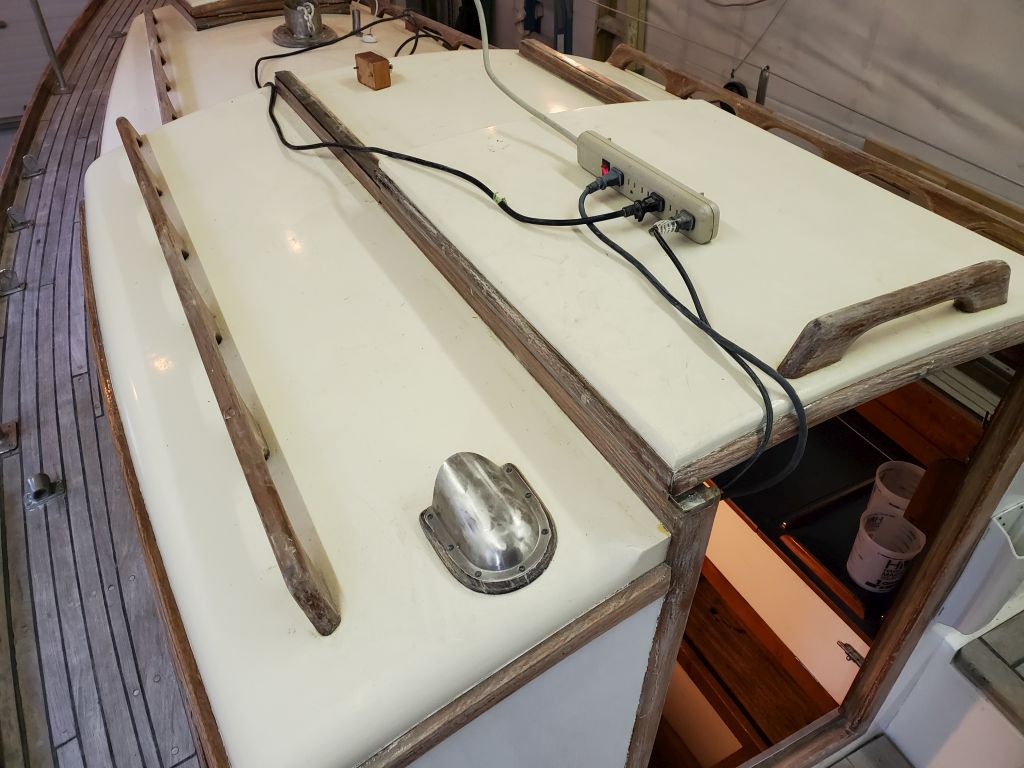
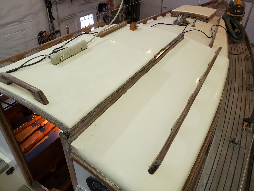
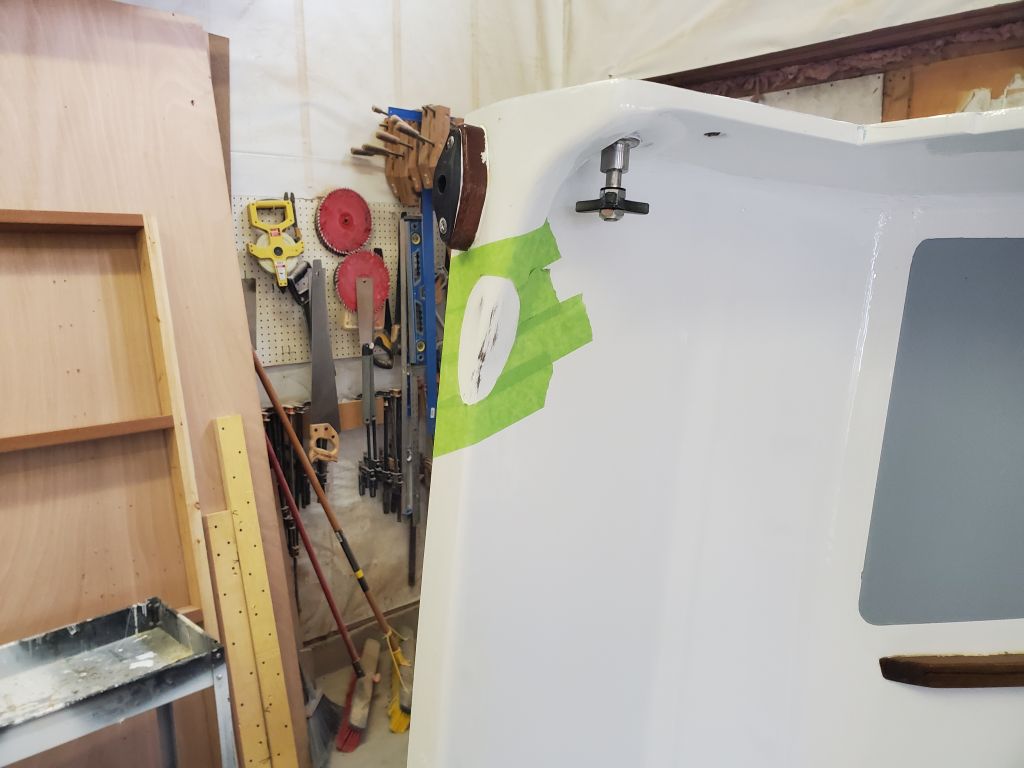
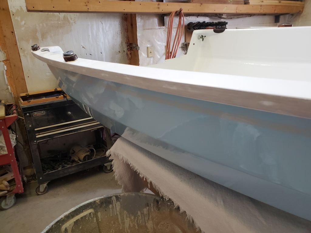
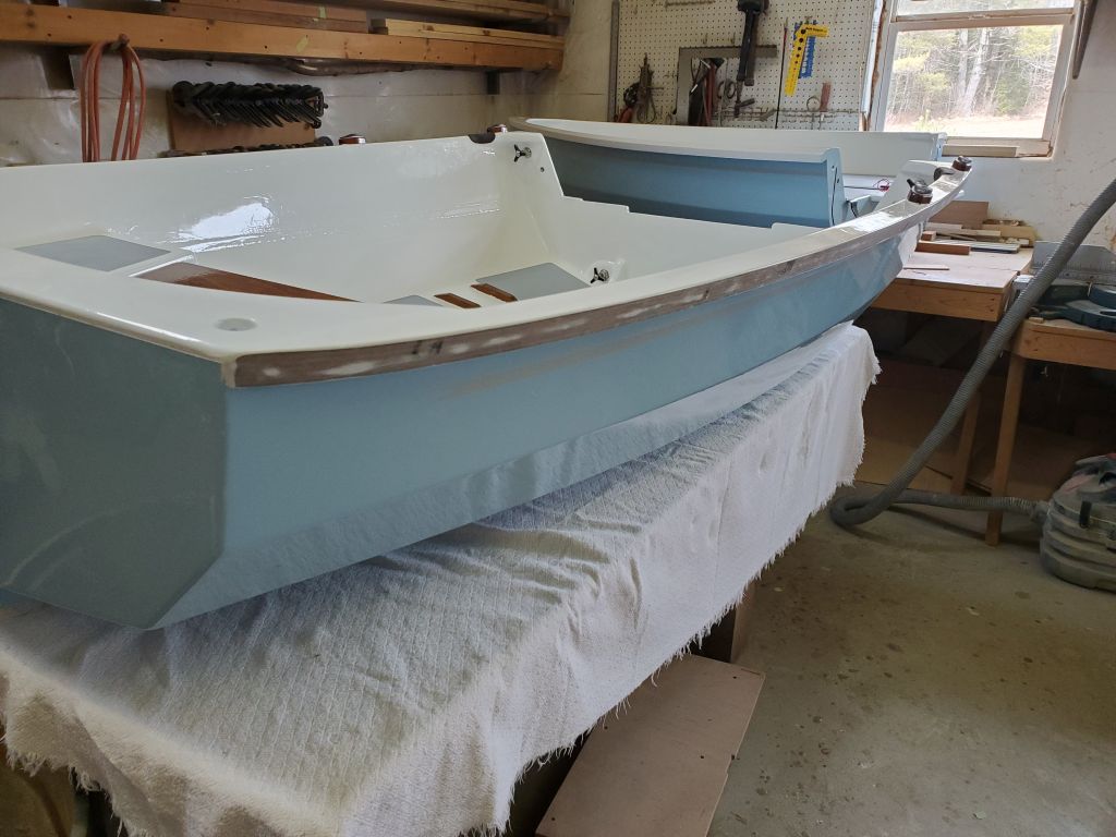
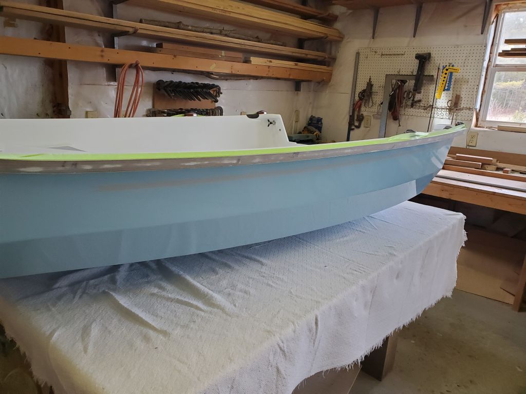
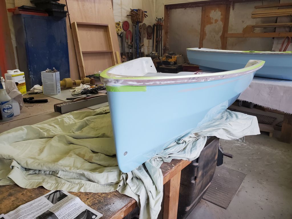
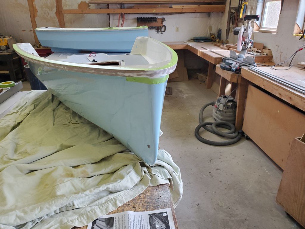
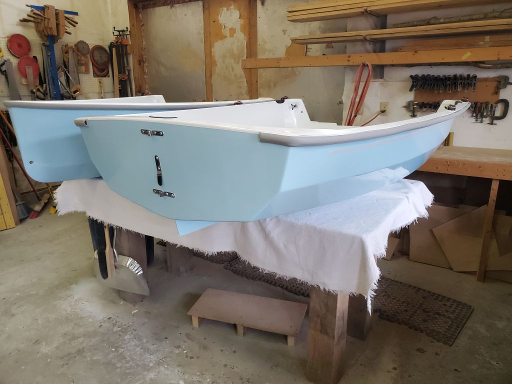
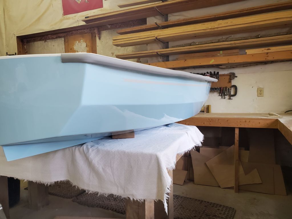
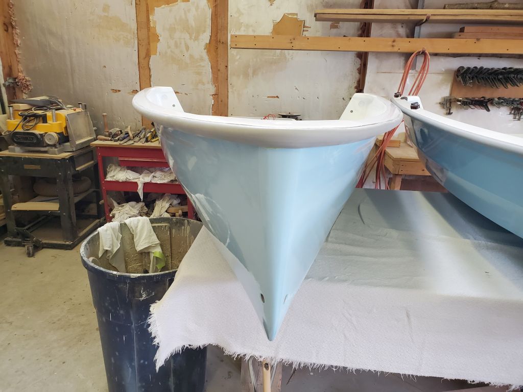
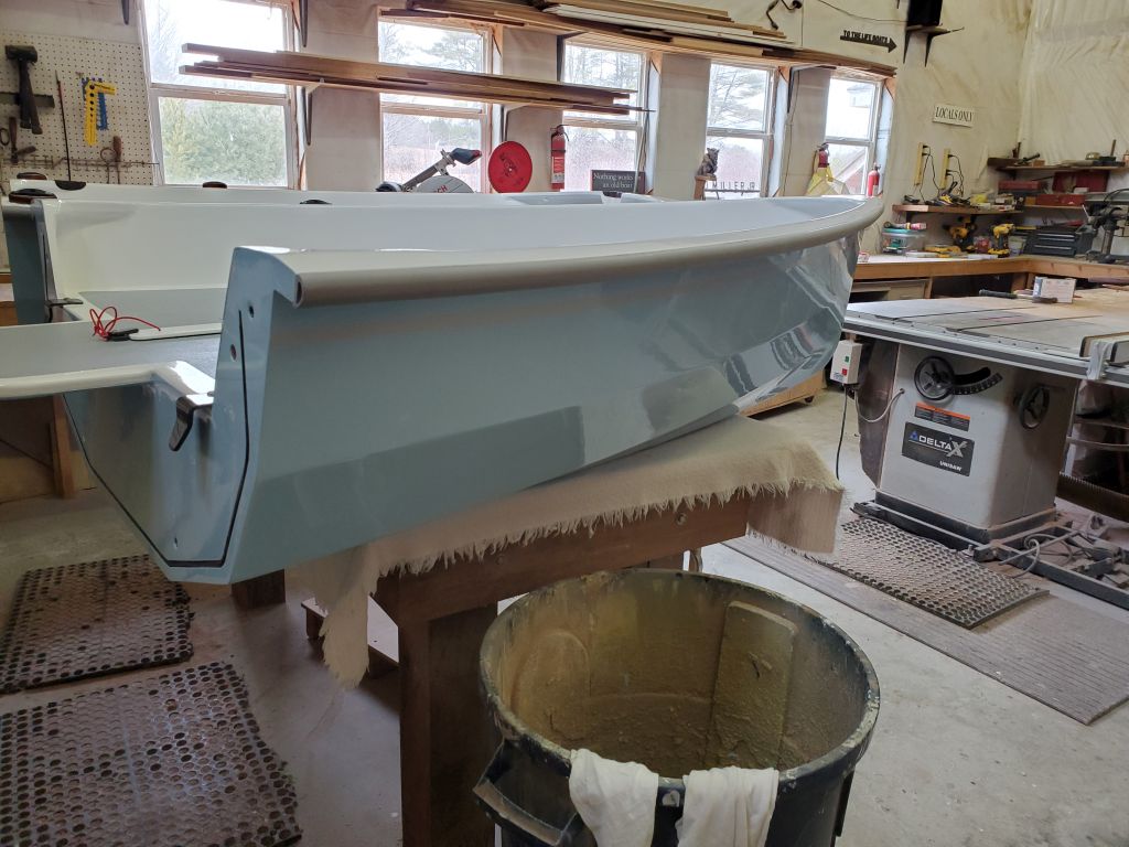
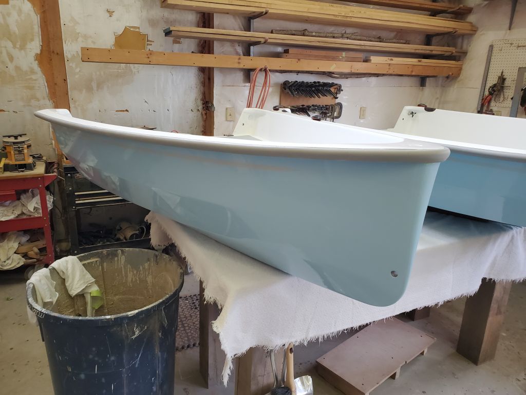
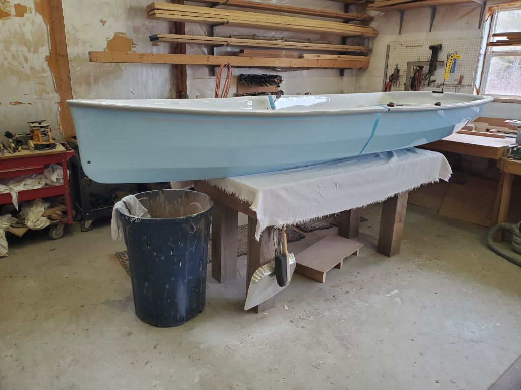
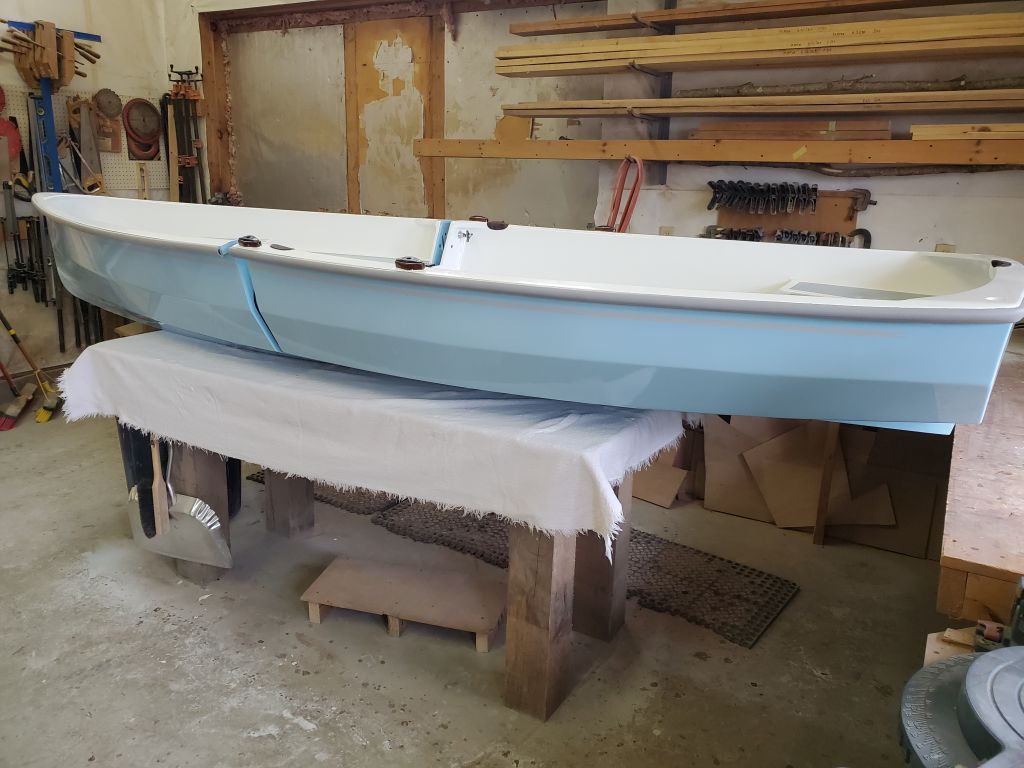
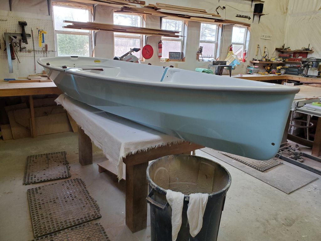
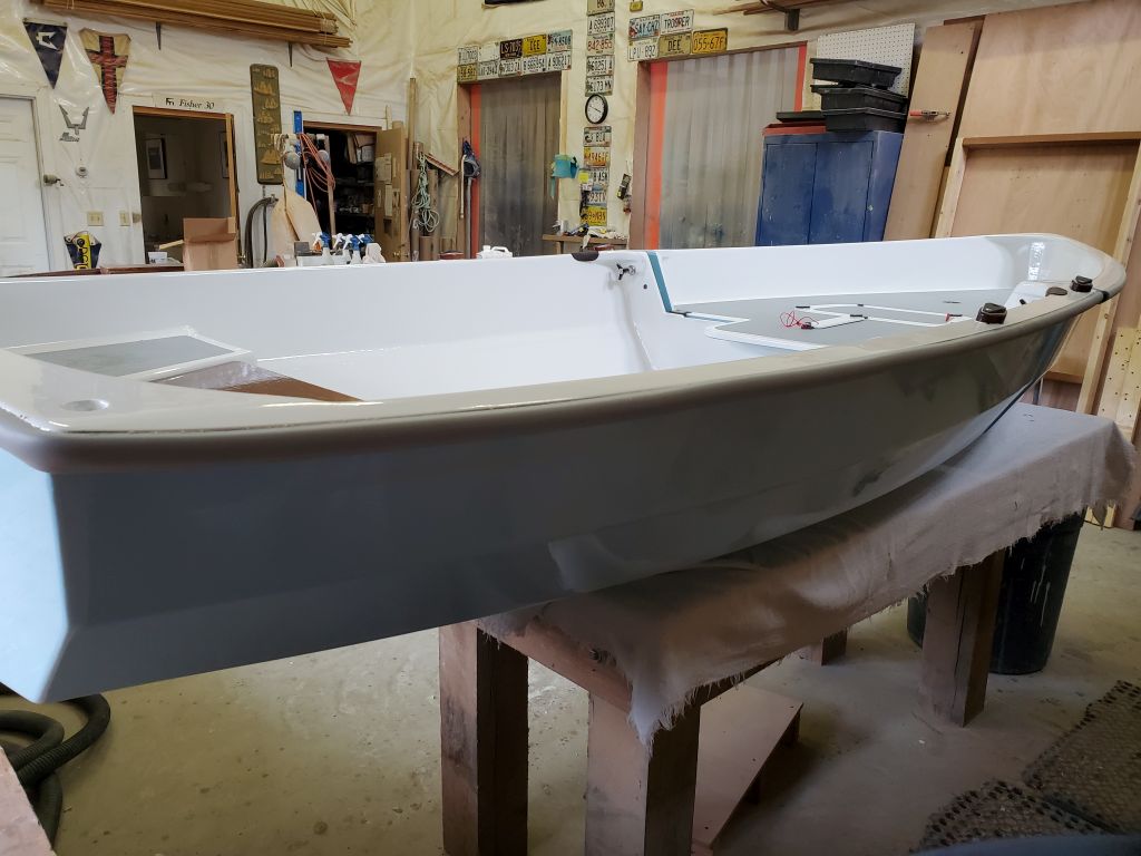
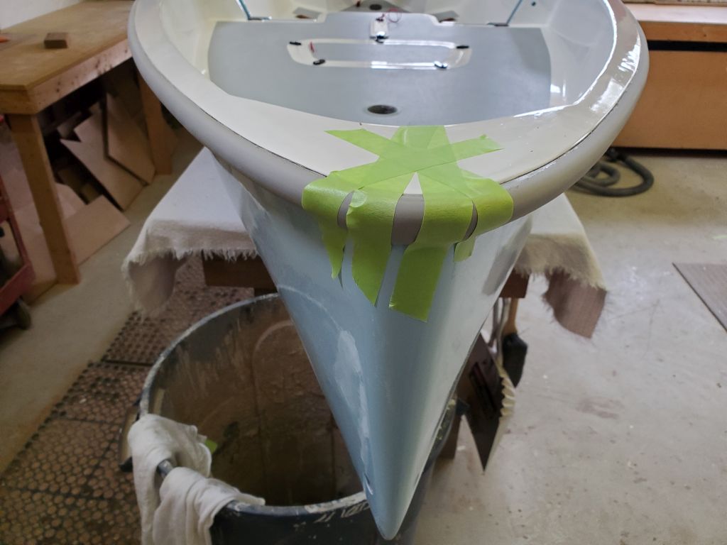
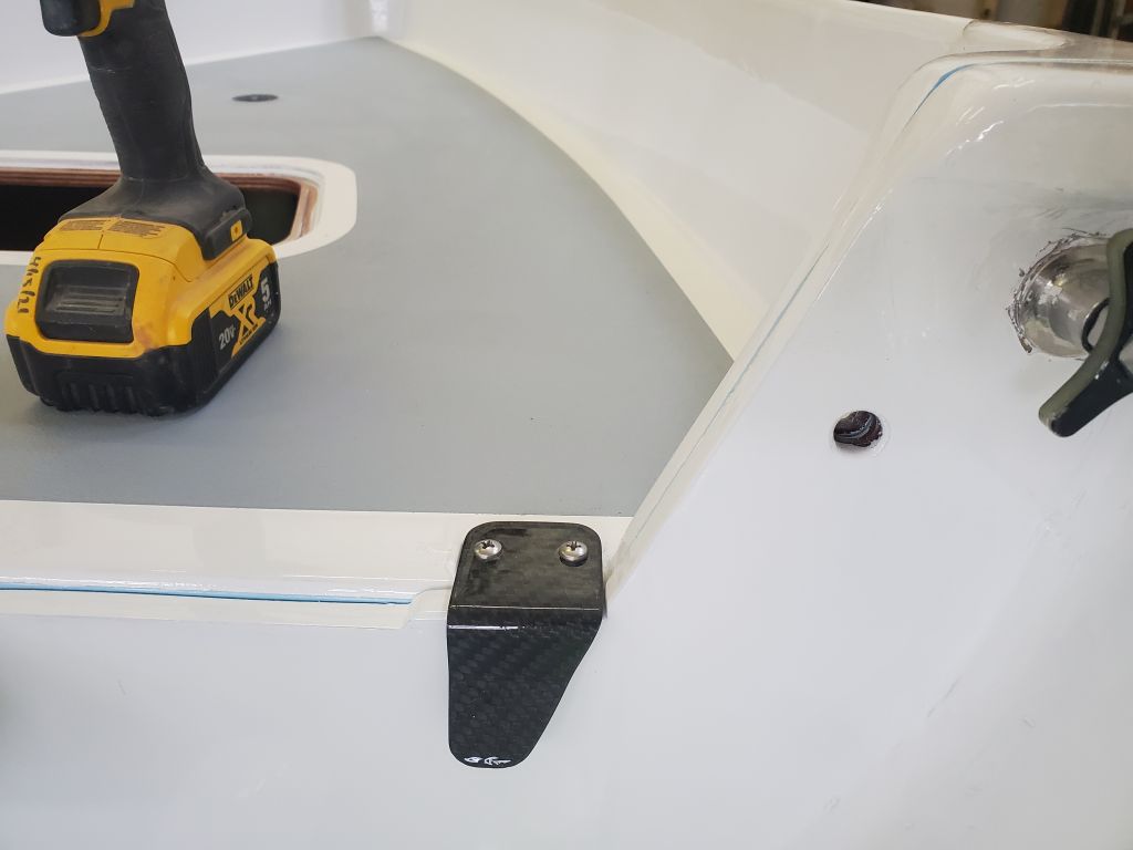
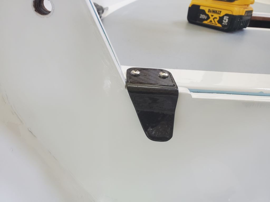
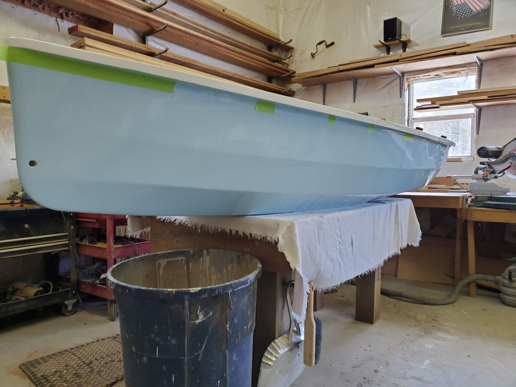
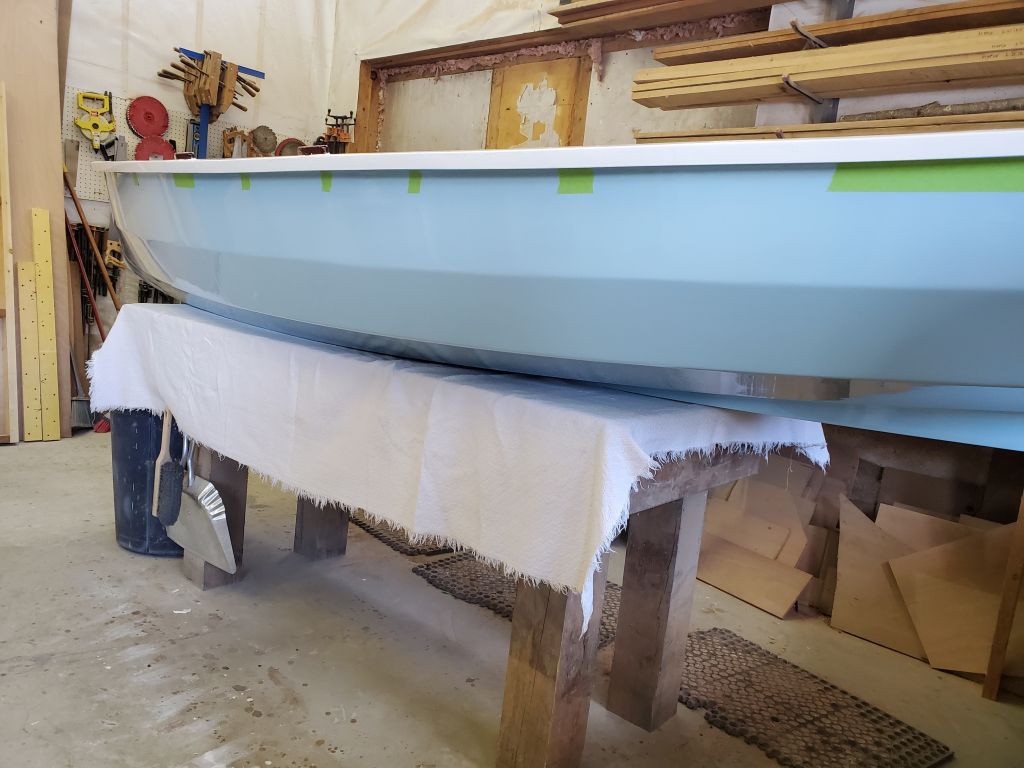
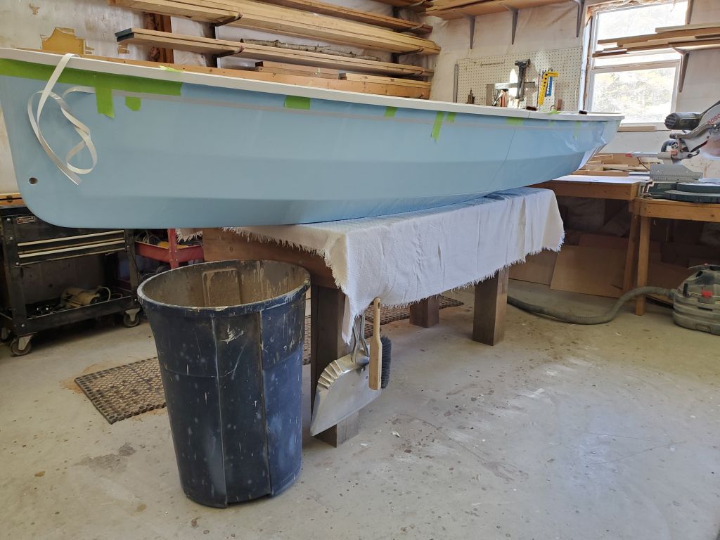
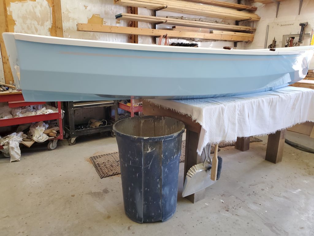
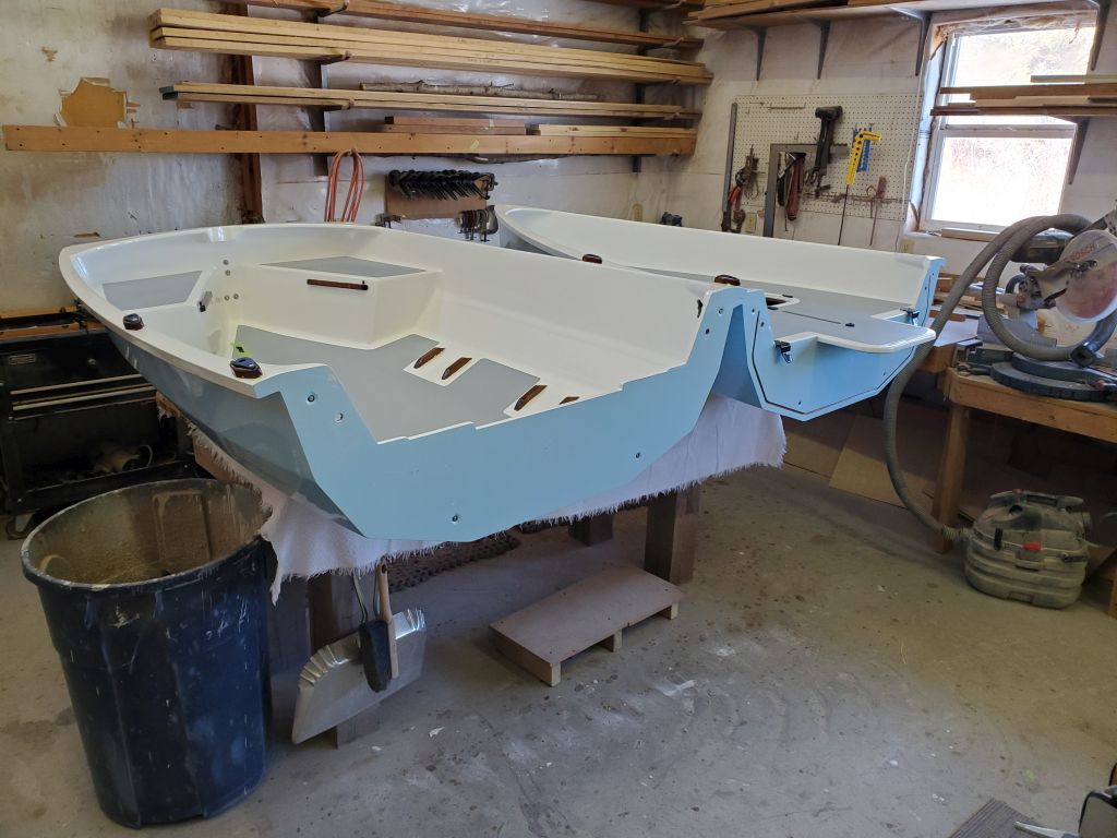
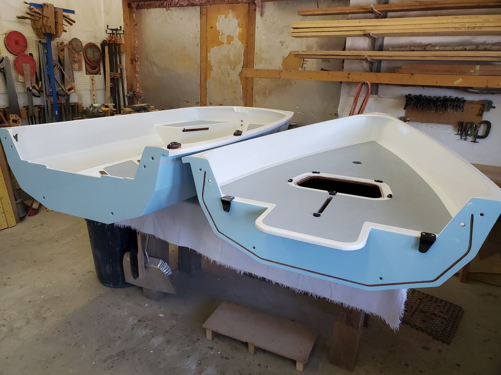
I propped the hulls closely together (but not connected) for the final photos. The book suggested masking over rubrail at the curve at the stem to hold it against a possible propensity to sag down while the glue started to fully cure overnight; I’d seen no suggestion it might do this in practice, but why take the chance, so I masked this area for security.
With that, the dinghy construction was complete: nothing remained on the to-do list or in the manuals.
To wrap up the project, I had a couple final videos still in the works that I planned to post soon, and will have some parting thoughts about the kit in due course as well.