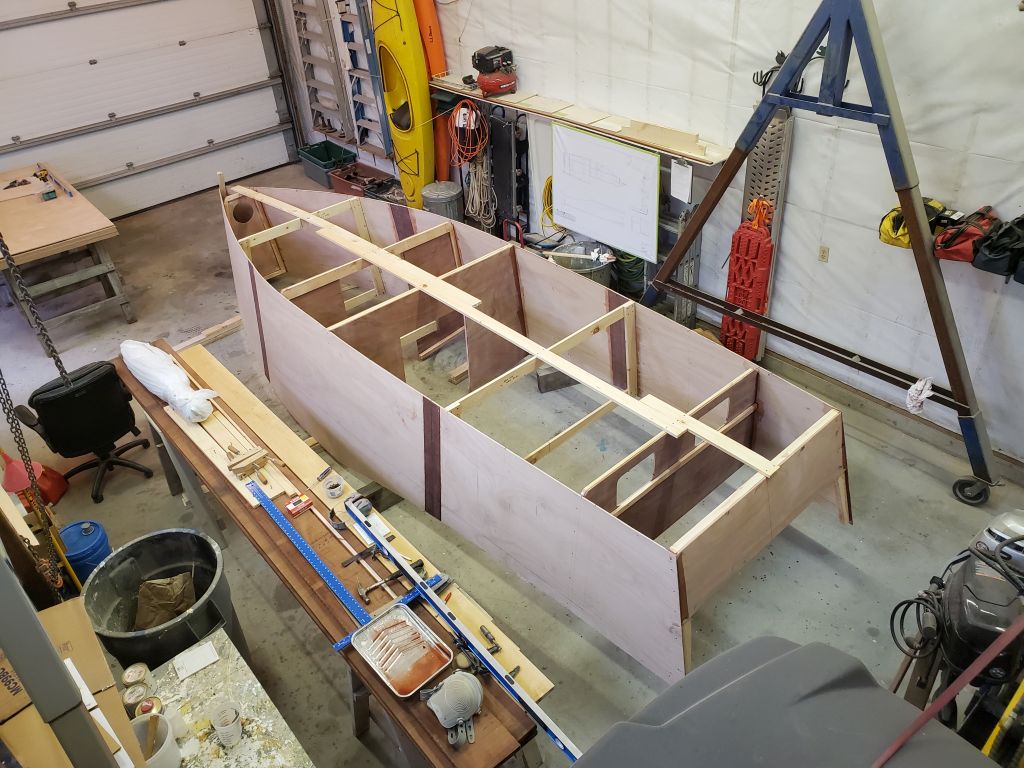
Episode 7: Beginning the hull assembly. Work in this video happened between December 26-29, 2025. Project total through this video: 49.5 hours
If you find this interesting, please check out the future updates and subscribe to my channel on YouTube.


Episode 7: Beginning the hull assembly. Work in this video happened between December 26-29, 2025. Project total through this video: 49.5 hours
If you find this interesting, please check out the future updates and subscribe to my channel on YouTube.
In Episode 6, I take care of a couple final details required before I could begin assembly of the boat. Specifically, I used measurements from the inside faces of the two hull panels to transfer the sheerline, or gunwale, position to the exterior of the hull, where it’d be needed for actual installation of the trim later. Then, I epoxy-coated all sides of all the bulkheads and transom to prepare them for installation.
The work in this episode occurred between December 12-23, 2025. Project total hours to date as of this video: 43.25
If you find this interesting, please check out the future updates and subscribe to my channel on YouTube.
Episode 5, covering the construction of the bulkheads and related framing, is now live. This covers work between December 5-19, 2025. Project total to date: 41 hours.
If you find this interesting, please check out the future updates and subscribe to my channel on YouTube.
Episode 4 posted on 12/17/25. This details work performed December 7-11, 2025. Project total hours to date: 30.25
If you find this interesting, please check out the future updates and subscribe to my channel on YouTube.
Episode 3 is now live. This details work performed December 4-6, 2025. Total project hours to date as of this video: 16.75 (including some work not yet shown)
If you find this interesting, please check out the future updates and subscribe to my channel on YouTube.
Episode 2 is now live. This video includes work done between November 25-27, 2025. Total hours to date: 8
If you find this interesting, please check out the future updates and subscribe to my channel on YouTube.
The saying goes that man plans, and God laughs. Adapting to changes in circumstance is challenging to some, but to others it offers new challenges and opportunities to be absorbed.
And so it was that in early 2022, I was fortunate to inherit a rundown but otherwise desirable waterfront property in Virginia from my uncle.
(Bear with me, the background is relevant here.)
This shakeup in circumstance forced some other changes, but my wife and I happily adapted and made changes, sold another property we’d owned for 13 years, and spent as much time as we could over the past few years working on our new property, restoring the overgrown wasteland of the property to something more open and attractive, and disposing of 13 huge dumpsters’ worth of accumulated hoard from the house and land in the process, while restoring and otherwise improving the small 1940s era concrete house to livable and even (dare I say) cute condition. We built a new dock to replace the derelict original, but there was no time for boats.
Till now.
With the house situated on a protected creek shooting off another, larger creek leading to Chesapeake Bay itself–all perfect for casual exploring and sightseeing–we knew the time would come for a boat, but what kind of boat? Our spot isn’t navigable by deep draft boats–and I had no desire for a cruising sailboat or larger powerboat anyway–so clearly it’d be a small runabout of one form or another.
But one thing I knew for sure: I didn’t want some old boat with a massive outboard and all its inherent problems, and couldn’t afford anything with a new outboard. Plus, waters are shallow where we are, with shifting channels, and something small and shallow was the best way to go.
Enter the AF4. Not the most descriptively-named design, but after a friend told me about it, I learned that it might well be something good for us. This little boat, designed by Jim Michalak–a sort of George Buehler for affordable trailer boats–had a lot going for it–practicality, low construction cost and most importantly it only needed a small outboard, something that the budget could probably handle.
So here we are. I’m building a 21-foot version of this boat, specifically called the AF4 Grande, or AF4-G for short. Rolls right off the tongue, doesn’t it. AF, which is a name the designer used for at least four designs (AF1, AF2, AF3, and AF4), stands for “Allison’s Fiddle”. I don’t know why, but there you are.
My thinking now is that this will be a video-only project, but we’ll see. I wanted there to be some sort of background first, though.
In any event, here is the first video on this build. If you find this interesting, please check out the future updates and subscribe to my channel on YouTube.
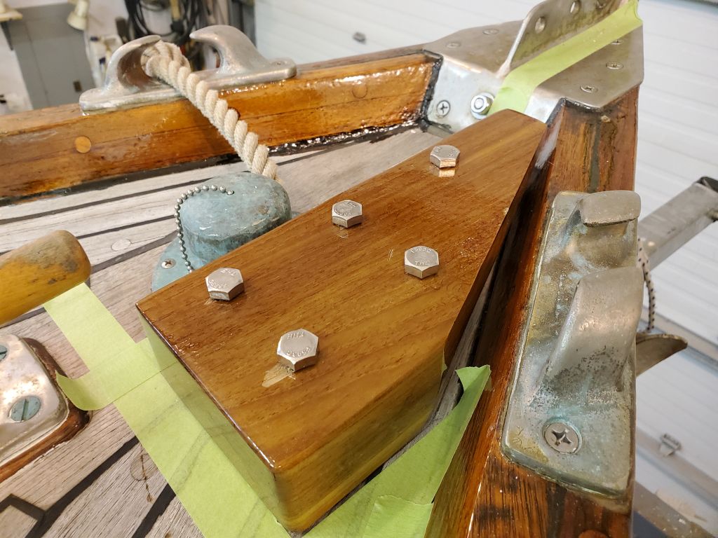
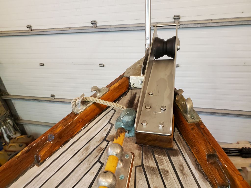
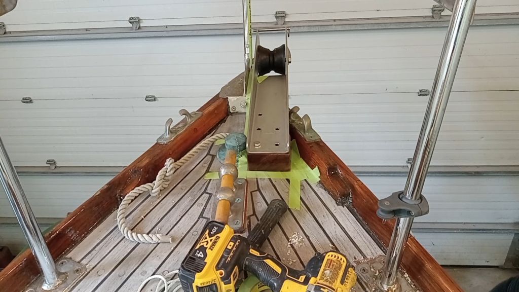
Now with the epoxy cured overnight, I was ready for the final anchor roller installation. I lined up the roller assembly and support block, and dropped in four of the five bolts, just allowing them to rest on the deck; this helped hold the block in alignment with the roller itself. I carefully lined up the whole thing with my various reference marks on the deck and elsewhere, then, with a 3/8″ bit, I drilled one hole all the way through the deck, and inserted a bolt to pin things.
Next, I removed one of the remaining four bolts and, after double-checking the alignment, drilled a second hole all the way through the deck, which pinned the assembly firmly and allowed me to more easily drill the remaining holes, first marking them by lightly drilling through the roller and block, then removing the assembly to finish the drilling through the deck.
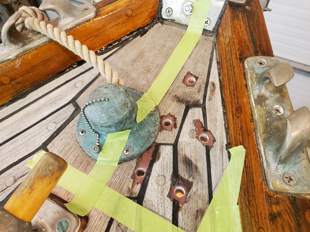
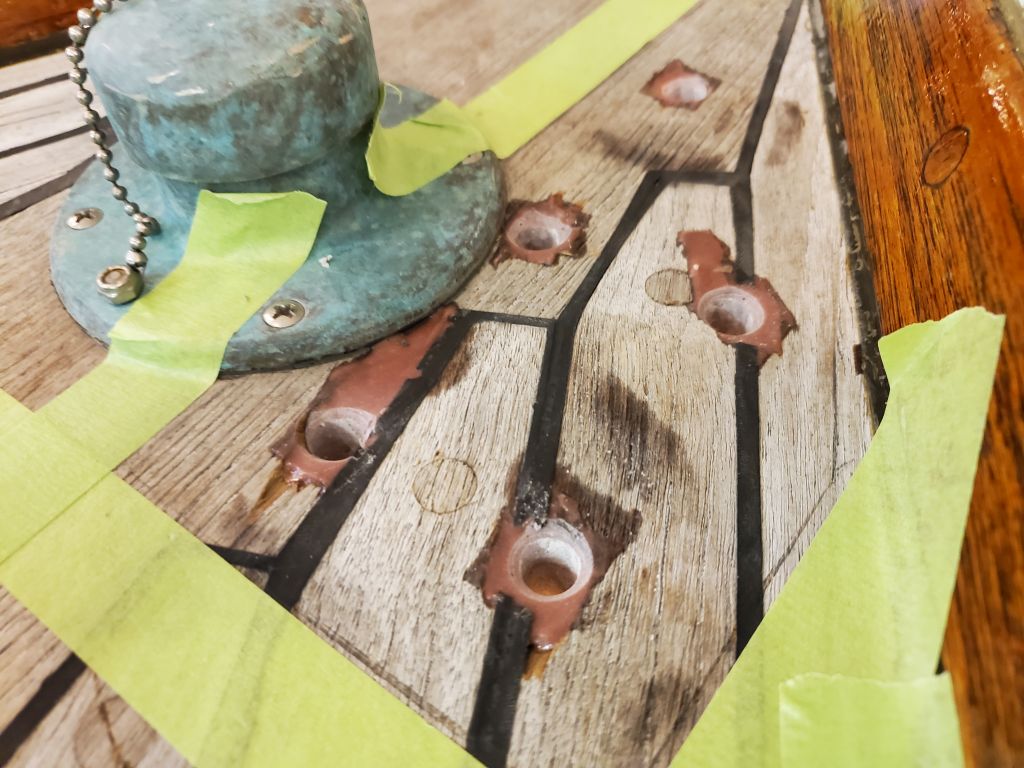
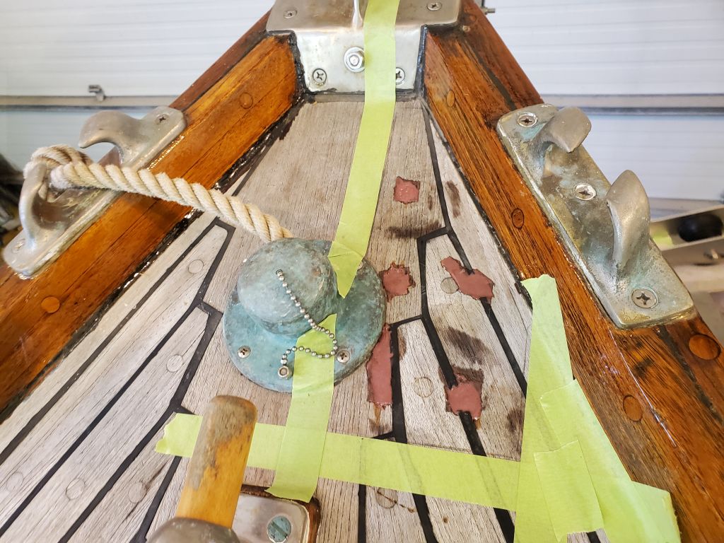
Afterwards, I milled small countersinks on each hole at deck level, allowing additional room for sealant at each hole. The drill spoils were all epoxy, meaning all the overfilled holes lined up as expected and desired.
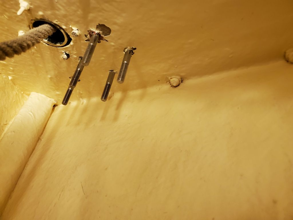
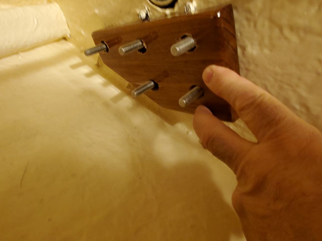
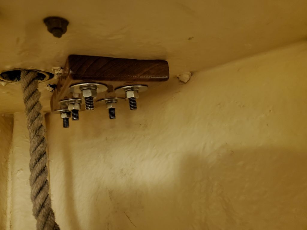
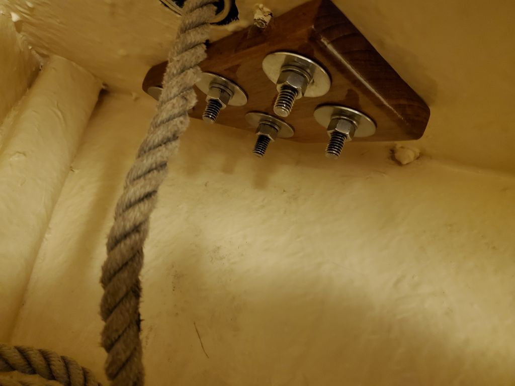
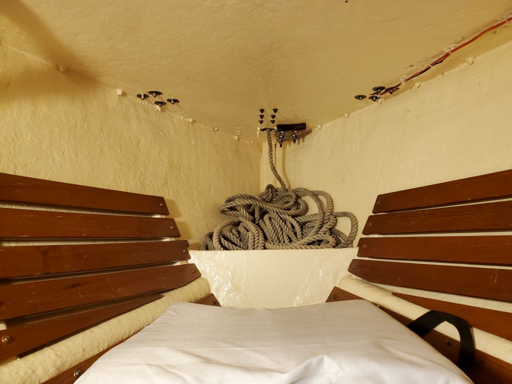
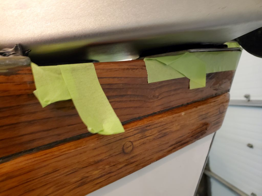
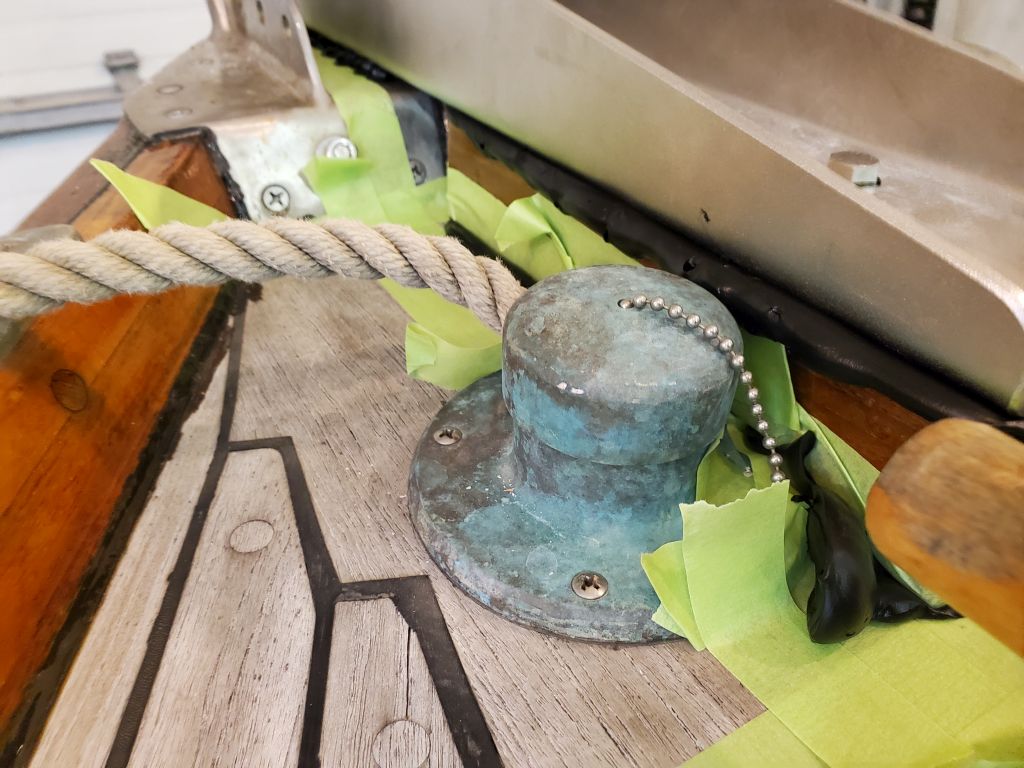
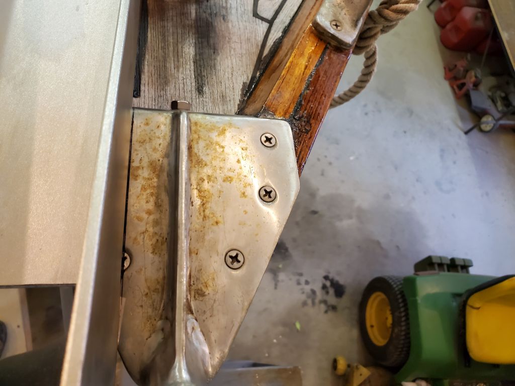
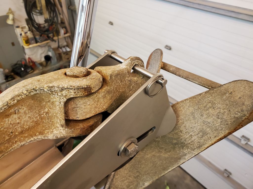
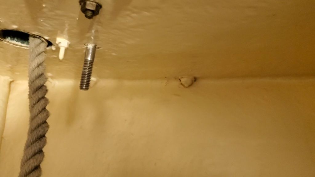
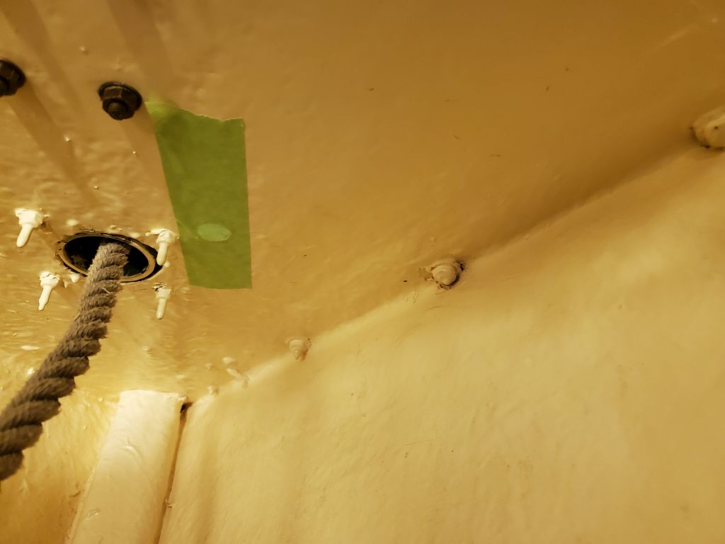
Next, I dry-fit the support block and all the bolts, and from inside the chainlocker test-fit the backing plate. I’d already made a small modification by relieving part of the underside to clear some of the nuts securing the adjacent hawsepipe, but found I had to trim the forward end, where it angled into the side of the hull, just a bit for clearance before the backing plate would fit.
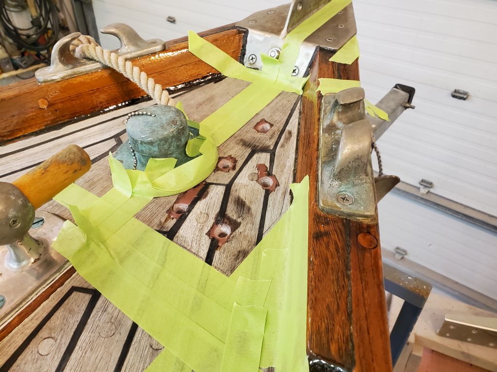
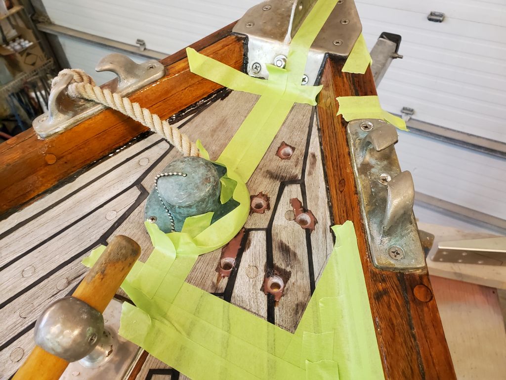
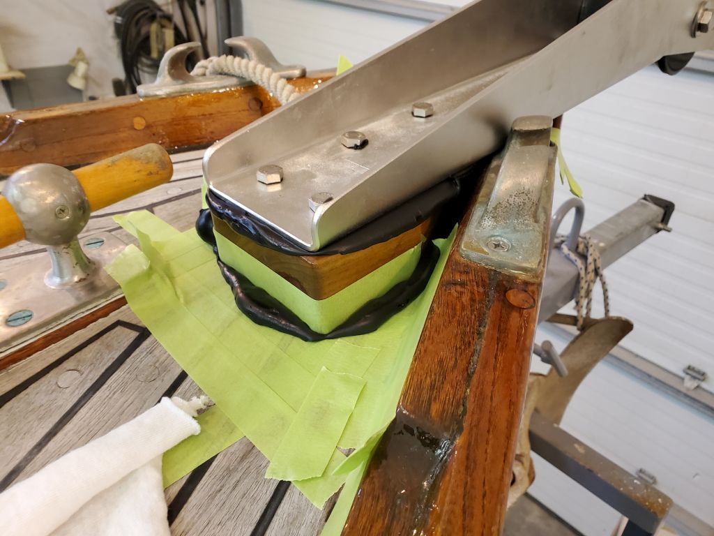
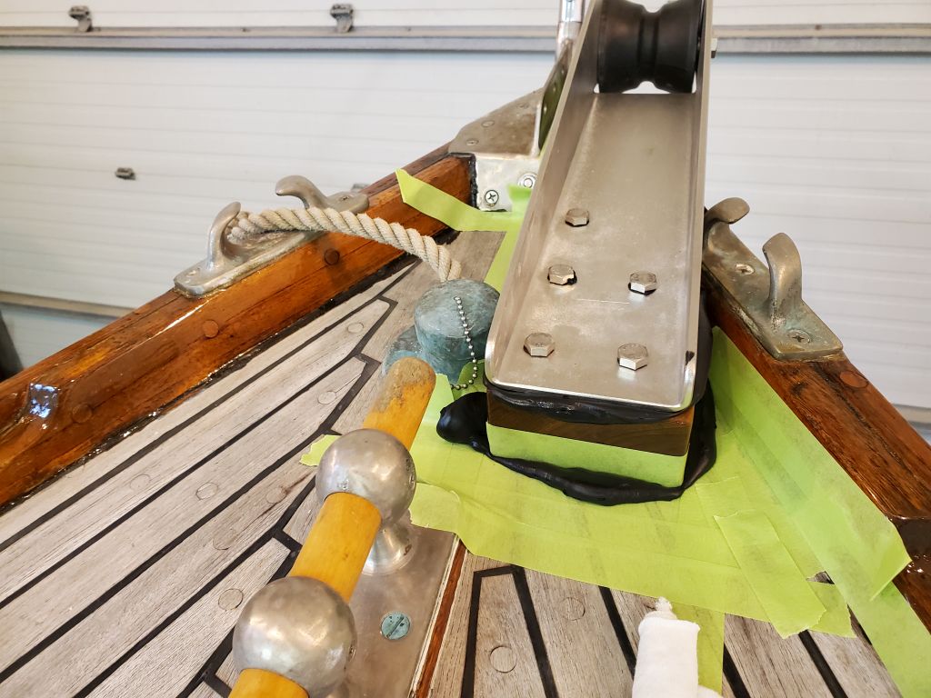
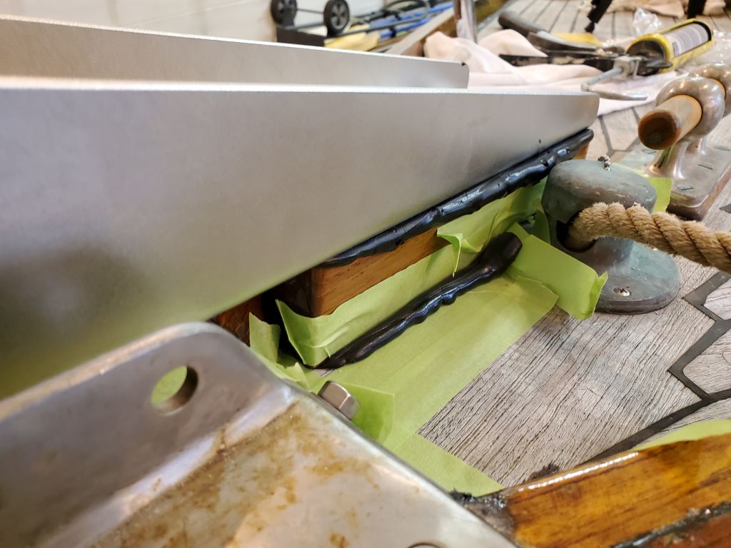
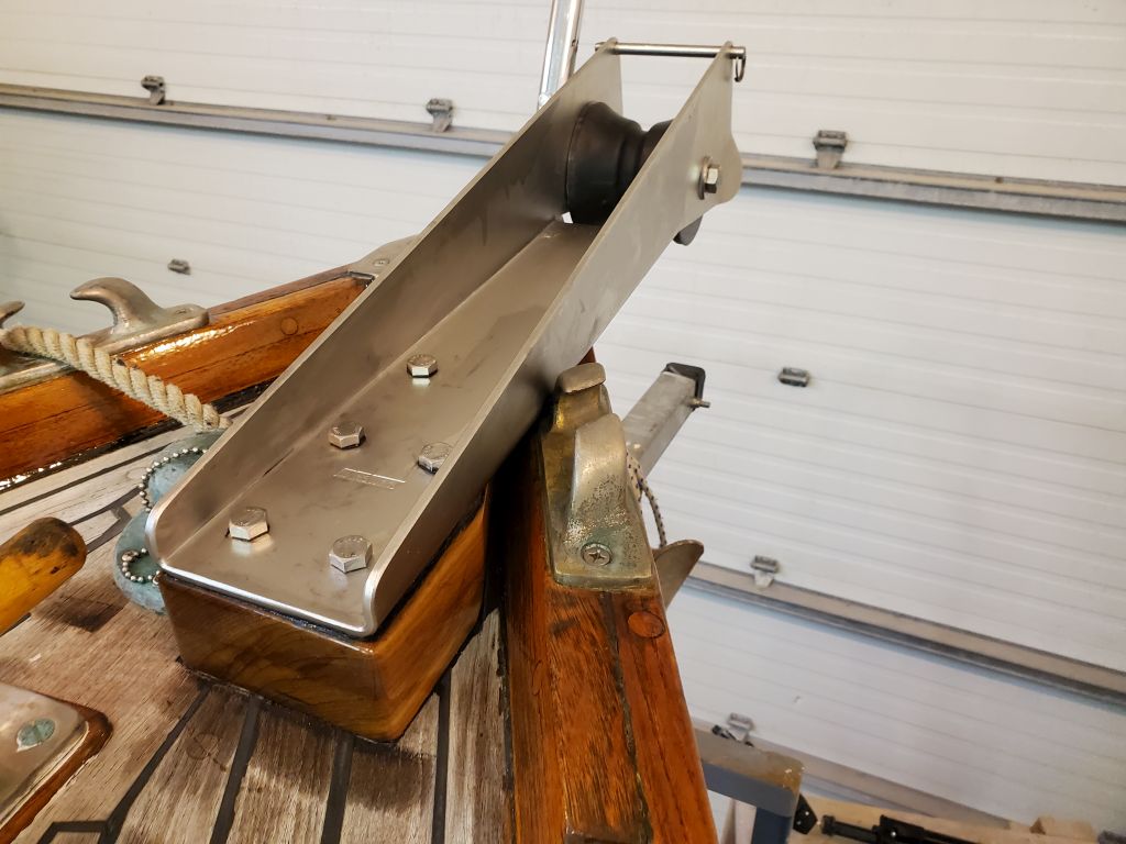
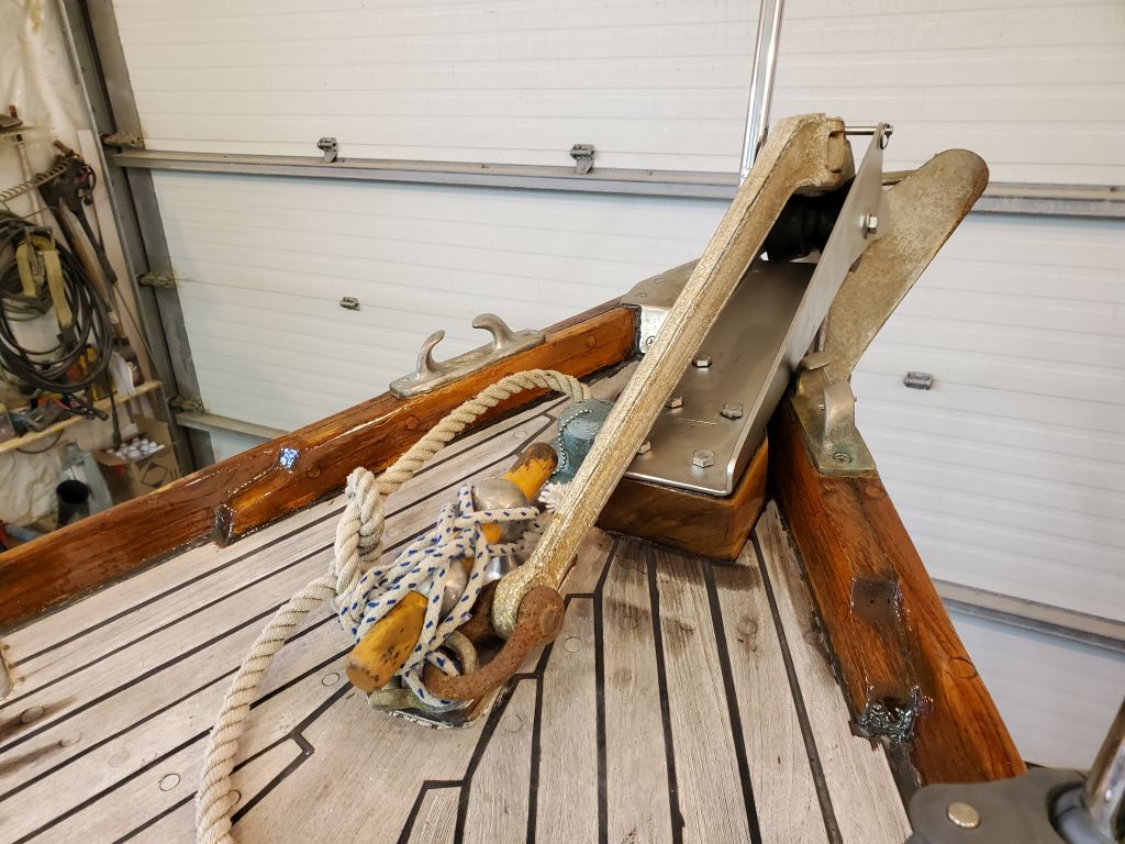
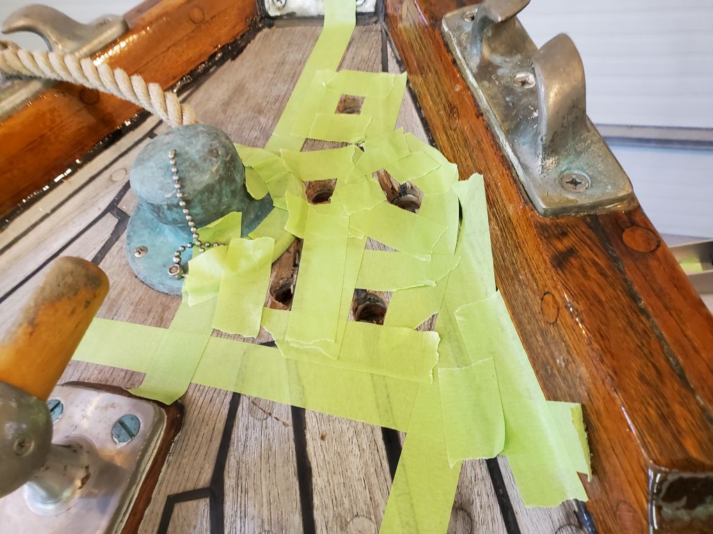
Back on deck, I made final preparations for the installation, setting up required tools and supplies, and adding some masking tape to increase coverage for deck protection. Then, I heavily applied black sealant–chosen because of the use of black sealant throughout the rest of the boat, and especially on the deck seams–to the deck before pressing the support block into position. Then, I applied more sealant atop the block and also to the stem plate and corner of the starboard chock, on which the roller itself also bore, and installed the roller and five bolts. I pressed this all down as much as possible, but tightening the bolts from beneath would really bring things home.
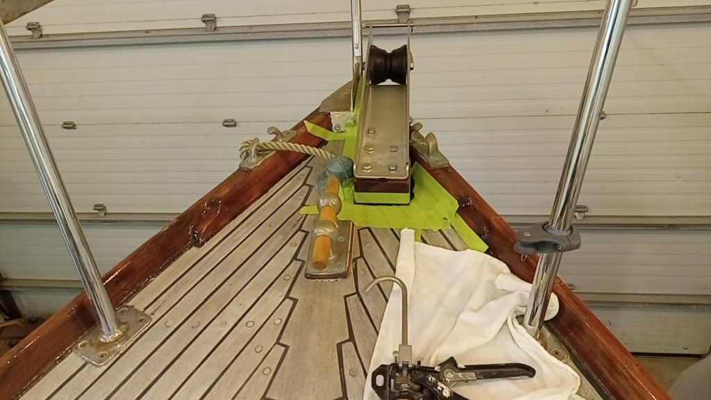
Now working from the chainlocker, I installed the backing plate and nuts, lockwashers, and fender washers on all the bolts, tightening them all securely. If the bolt spun at all, I used locking pliers on the exposed threads to hold it while working the nut with a ratcheting box end wrench. This allowed me to relatively easily complete all the work alone.
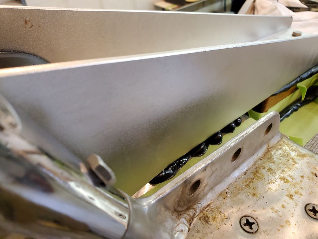
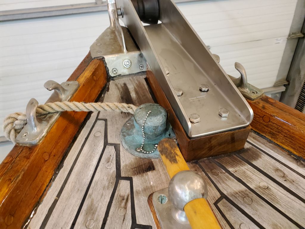
With all the bolts securely tightened, I returned to the deck and was happy to see lots of good squeezeout everywhere.
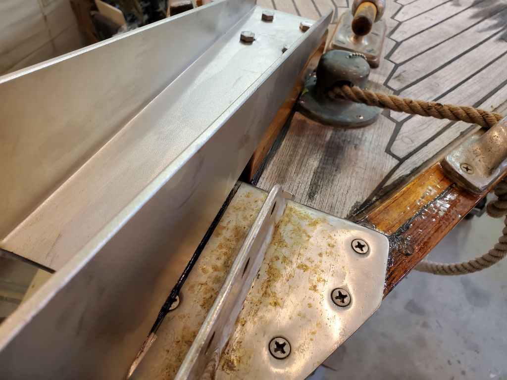
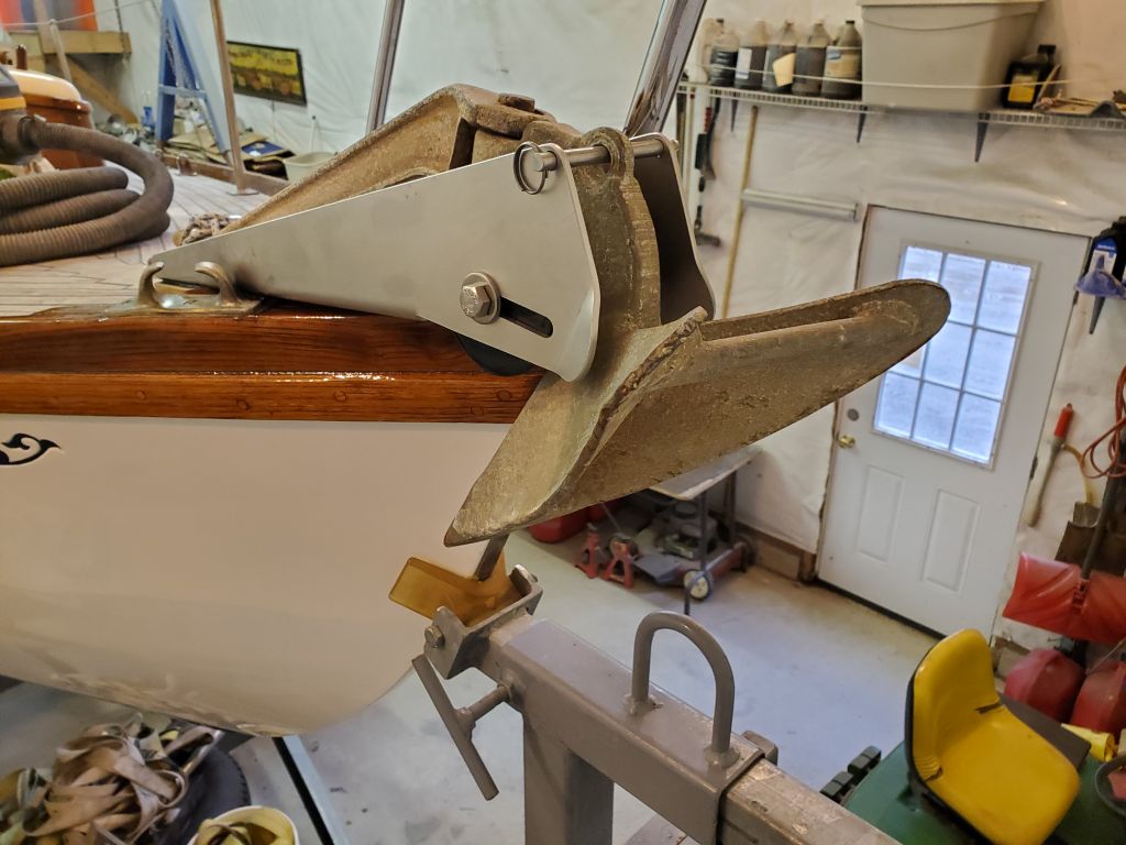
To finish the installation, I cleaned up all the sealant and removed the masking tape.
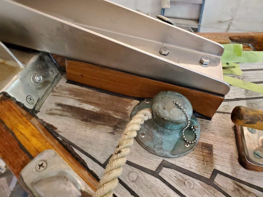
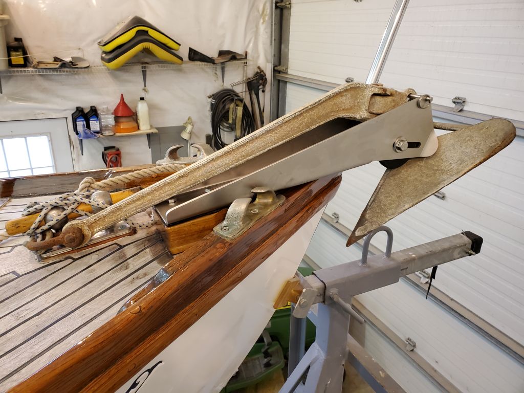
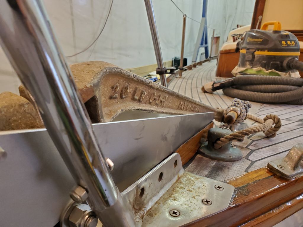
I double-checked the anchor fit in the roller afterwards.
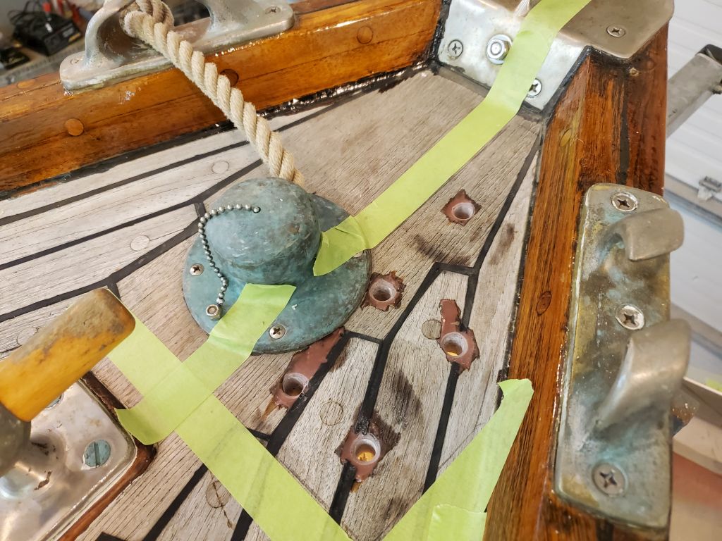
The next step towards final installation of the anchor roller was to locate and prepare the bolt holes through the deck. For this, I laid out the support block and used the roller to ensure it was aligned properly, then used a drill with a 3/8″ bit to mark and drill one hole all the way through the deck. This allowed me to install one bolt to help hold everything in position while I marked the rest, and also to confirm the length of the bolt I’d ordered, since I’d had to “educationally guess” the length since I didn’t know the overall deck thickness. As it happened, my guess (5″) was accurate, and with the roughly 1″ thick backing plate installed (not shown), the bolt length worked out well.
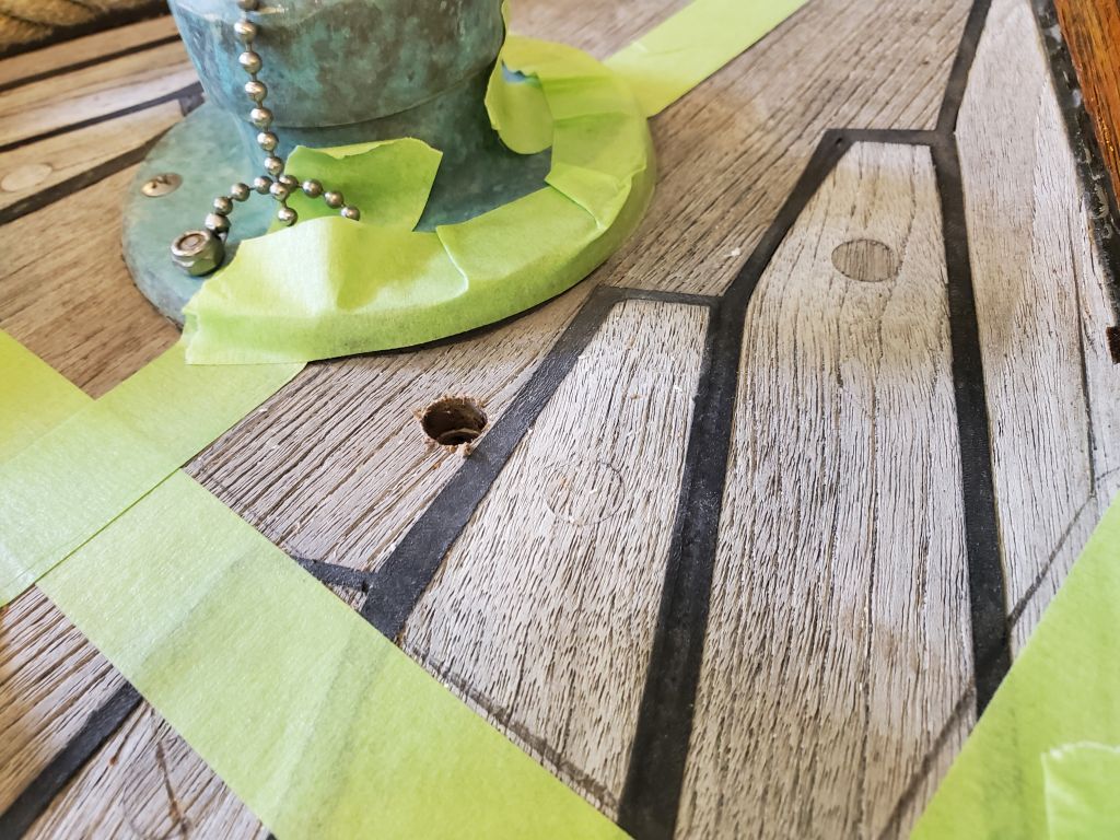
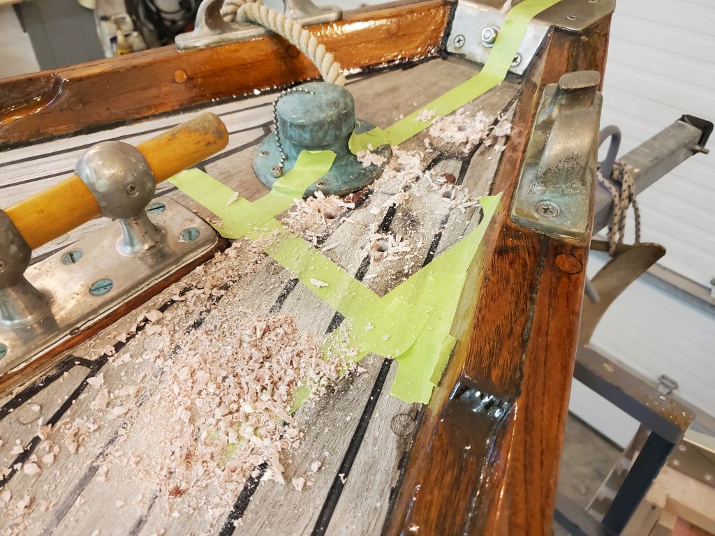
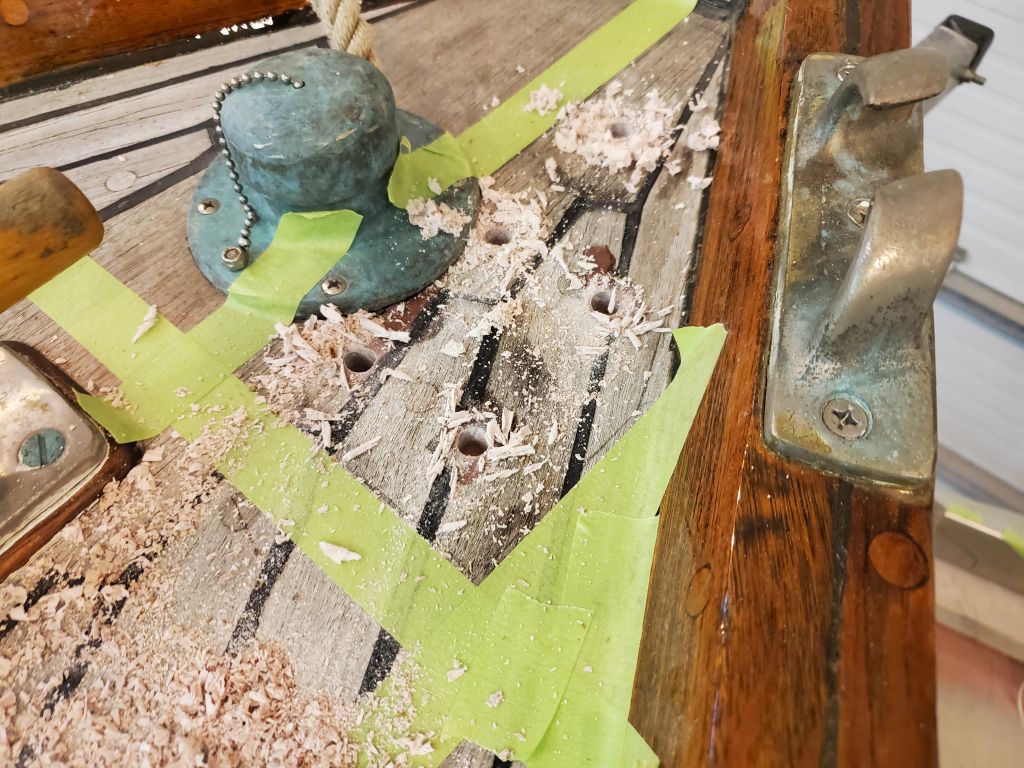
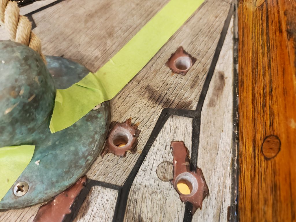
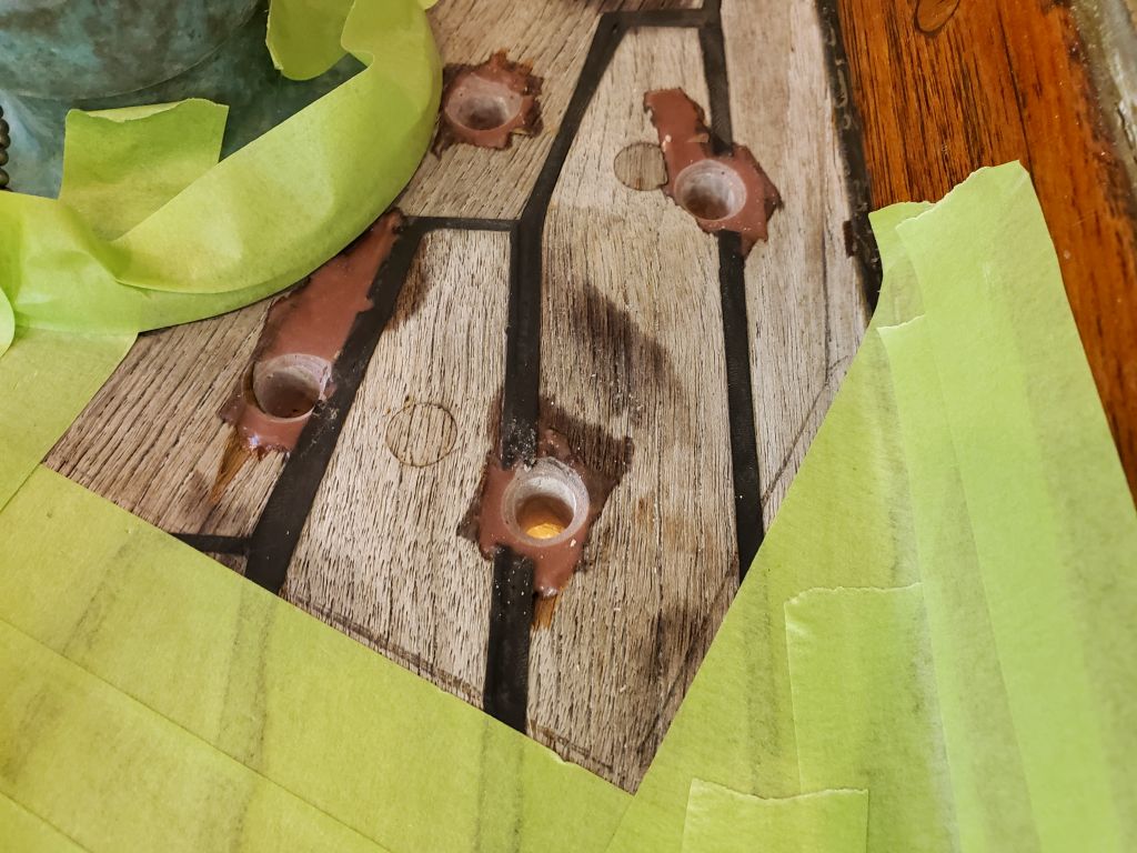
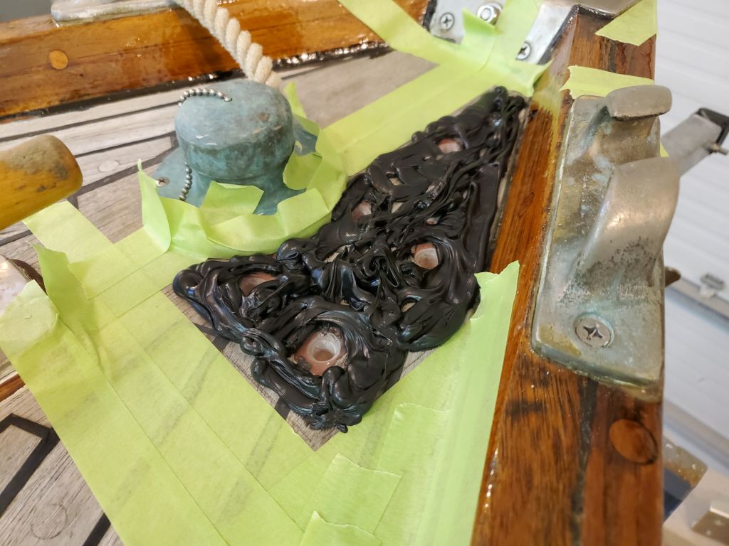
With one bolt pinning everything in place, I marked the remaining four holes, just into the deck, then removed the roller and base so I could prepare all the holes. Beneath the teak veneer on this deck was a “normal” fiberglass deck with core material, so I wanted to overbore the holes and fill with epoxy, to allow for a solid epoxy water barrier around each fastener when permanently installed. With all the holes just marked with the 3/8″ bit, I used a 5/8″ bit to drill further into the teak, enough so that I then had a starting point to use a 5/8″ Forstner bit to drill through the deck, core, and as far down as the inner skin, without going through. This removed all the core material and left a flat bottom in the holes. This would give me roughly 1/8″ of epoxy around the fastener in each hole.
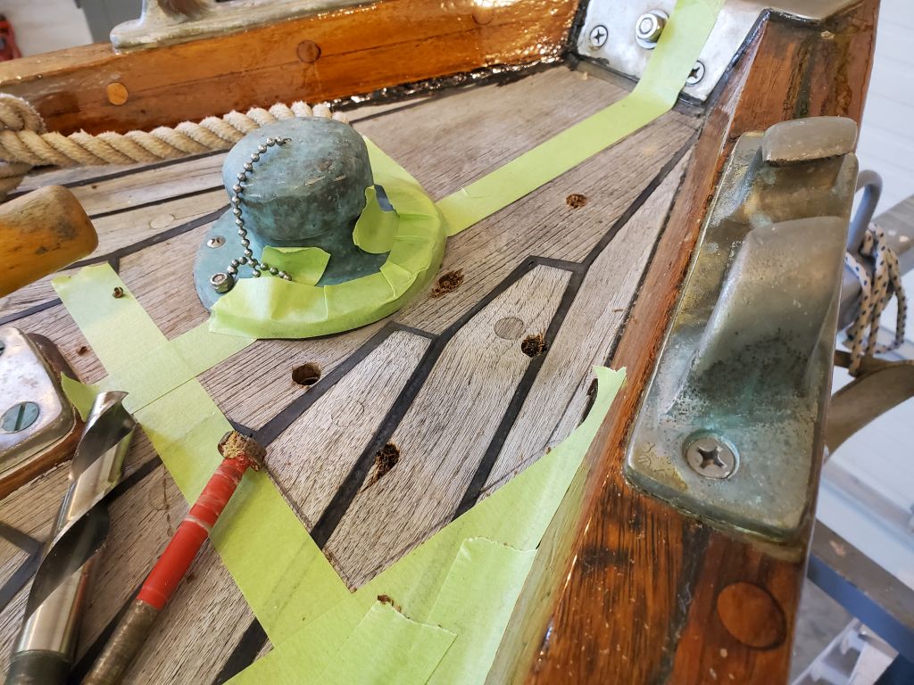
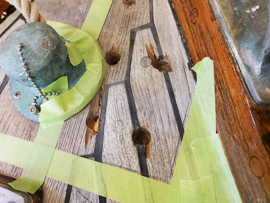
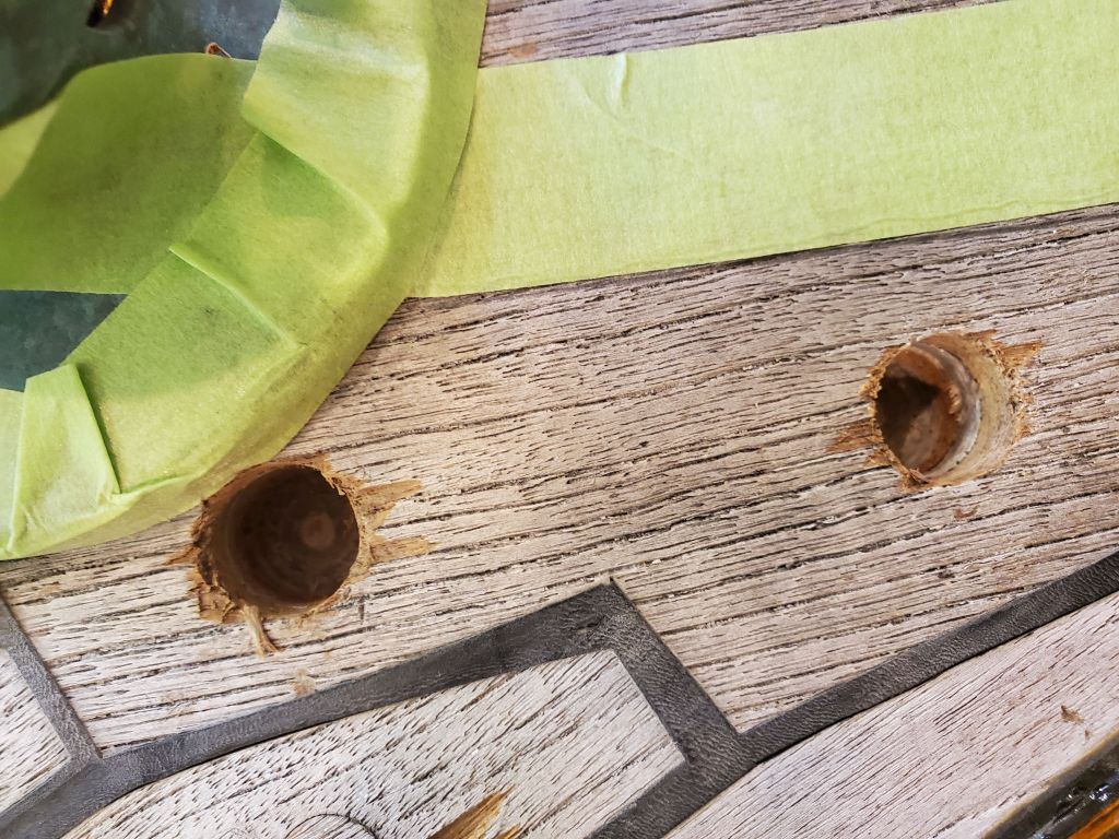
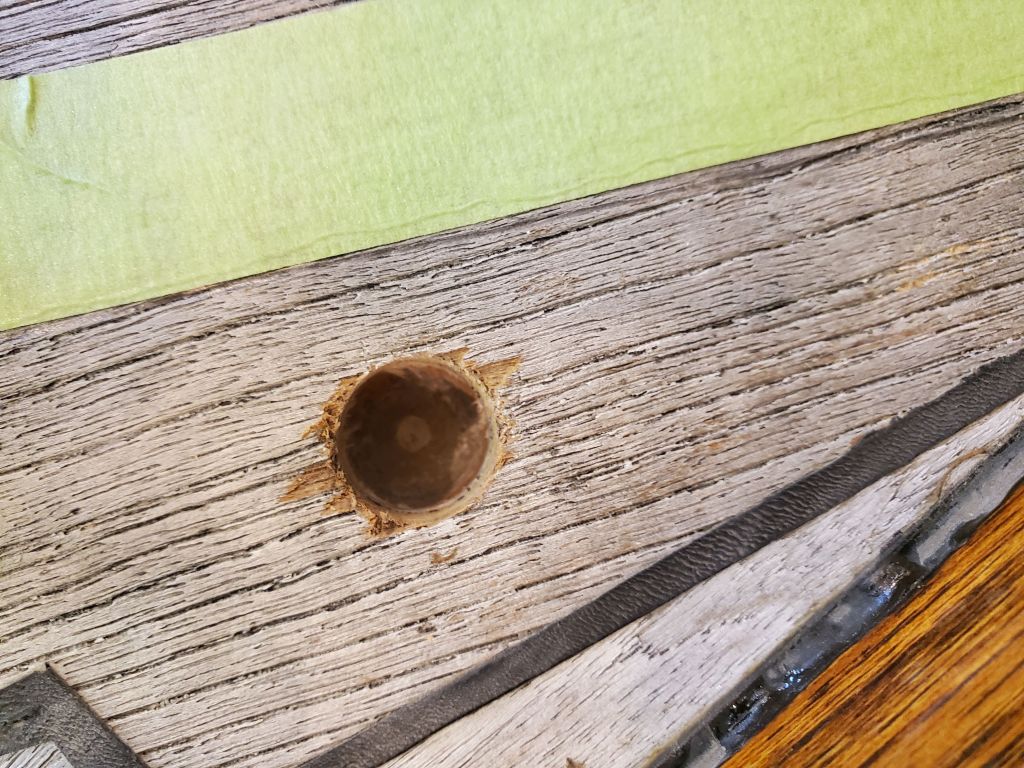
I also drilled out the initial through-hole, then covered it with tape from beneath to hold the epoxy, and I also masked off the deck around the holes, though this whole area would eventually be covered by the roller support block. I filled all the holes with a thickened, strengthened epoxy mixture, leaving it to cure overnight.
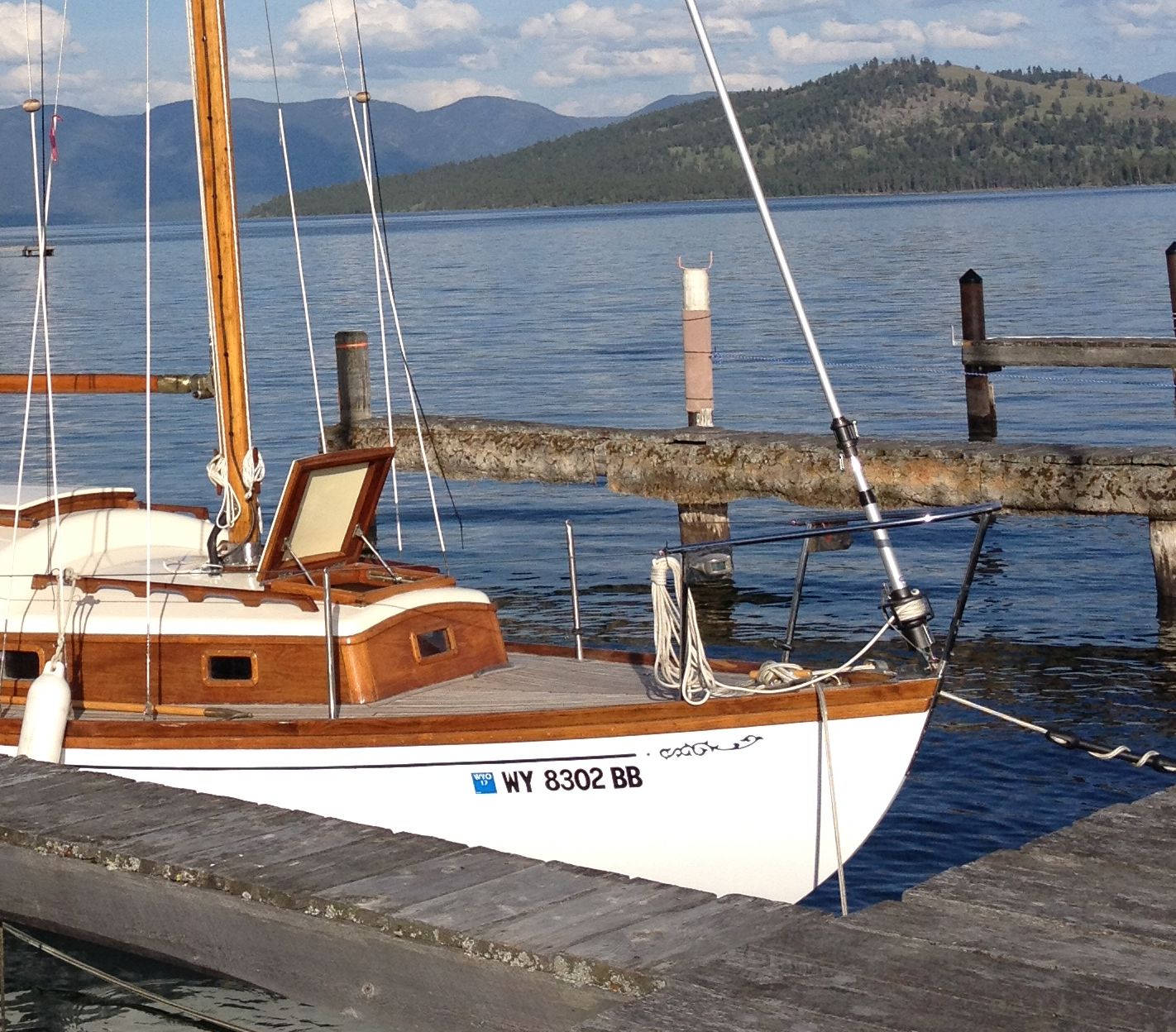
A helpful rigger at the boatyard where the mast was stored got some measurements of the drum and height for me. The bottom of the drum turned out to be 7″ above the pin at the headstay, and the diameter of the vertical cylinder (and also its height) beneath the drum was approximately 3″. These were the two crucial measurements I determined I needed to see how well the anchor and roller cleared.
To help me make a mockup, I also found some basic dimensions for the furler–or one similar to it–online. This gave me an idea of the diameter of the furler drum–9″.
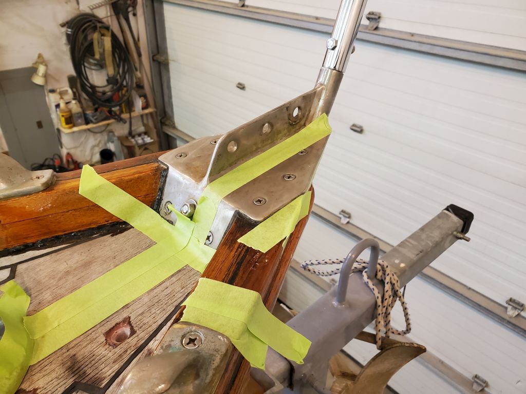
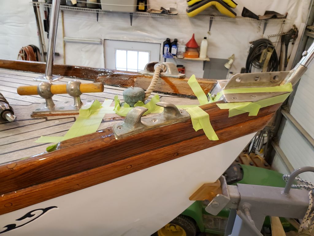
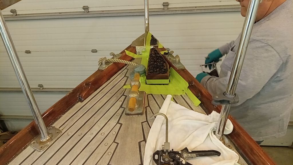
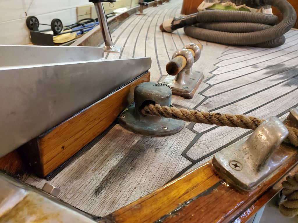
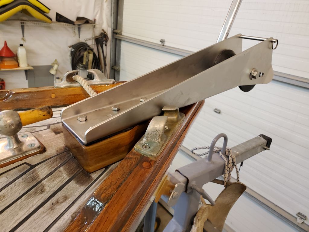
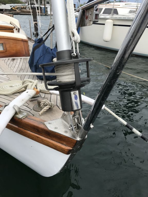
From these measurements, I built a crude mockup from cardboard and a roll of black tape that happened to be 3″ in diameter. I attached the components to a wooden stir stick, and clamped the arrangement to the stem plate at the approximate angle of the headstay, which I could figure from the ghost of the headstay fitting visible on the plate.
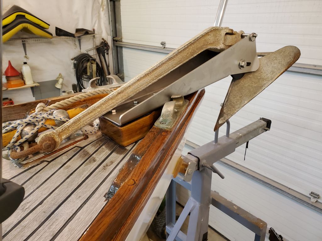
With the anchor and roller in place where they belonged, I was happy to see that there appeared to be no clearance issues with the drum (most important) and the cylinder beneath it (just about as important). Even better, there was plenty of room for error in the setup, in case my mockup was off (how could it be?) or to allow for other minor variations. I thought my drum mockup was a bit large in diameter, but it was the best information I could find and I’d rather it be too large than not large enough. In any event, the furler drum was well clear of the anchor, other than during times of manipulating the anchor in the roller itself, where (as is typical) some care would be required to keep the shank away from the drum when transitioning between anchor storage and deployment.
The first two photos show the actual furler in place for comparison against the mockup.
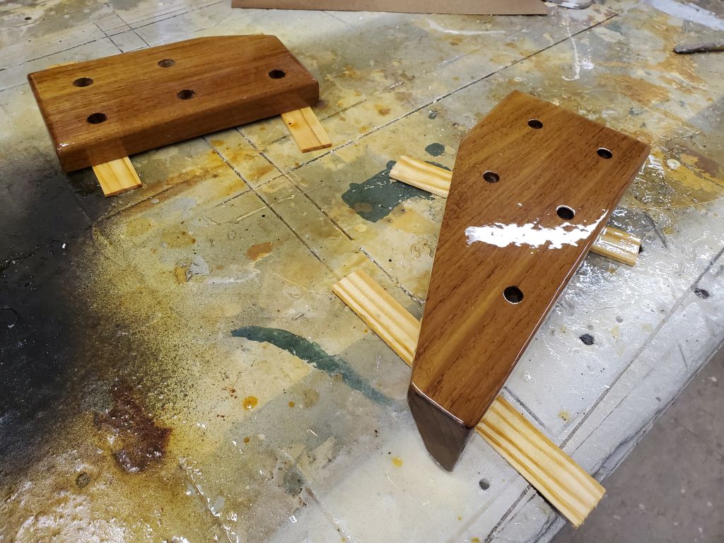
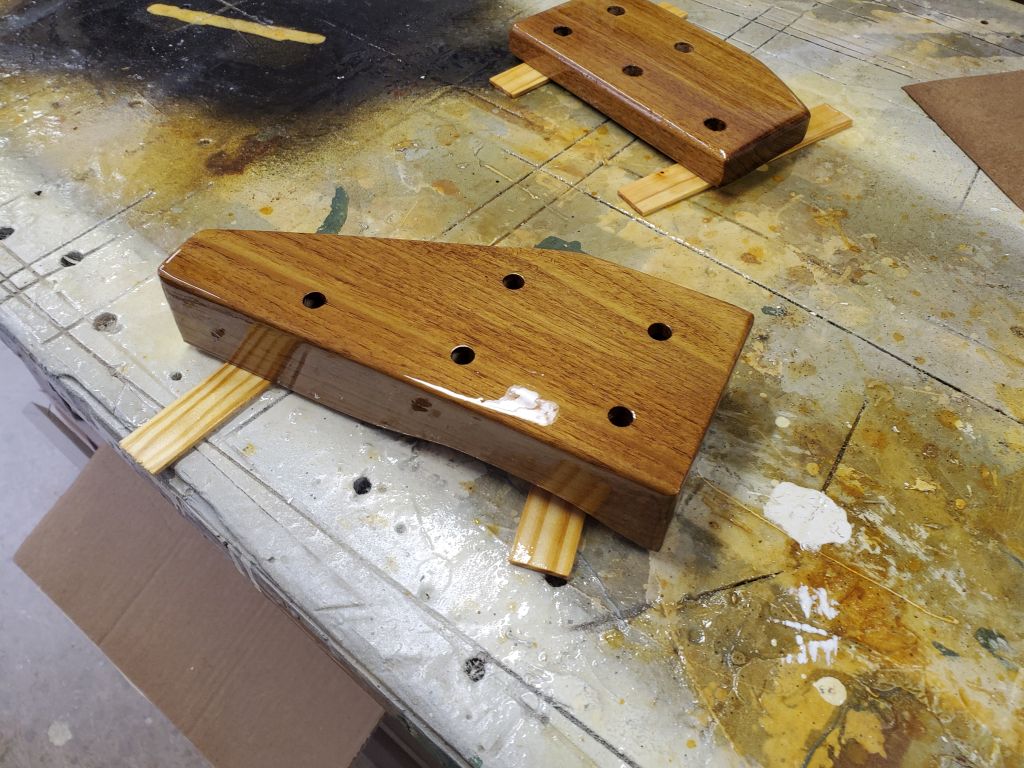
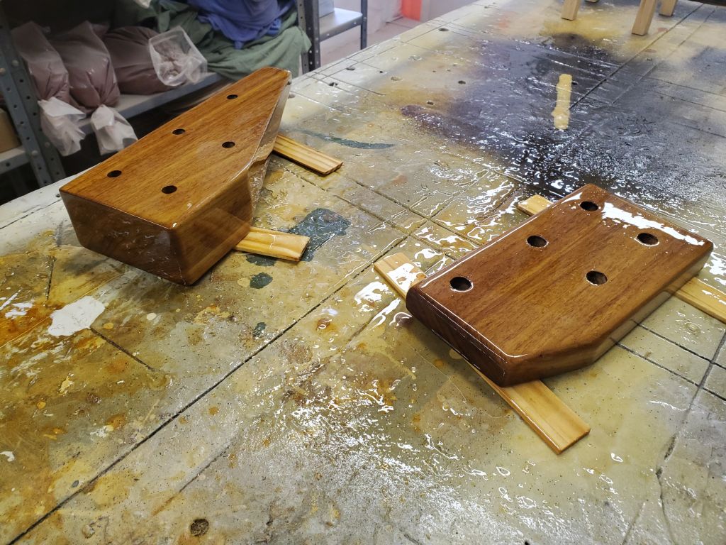
Given these findings, I planned to proceed with the final installation once the support block and backing block were ready for installation, after a bit more varnish, which process I continued now.
Finally, I removed the tape from the starboard deadlight, now that the trim and bungs had ample varnish buildup.