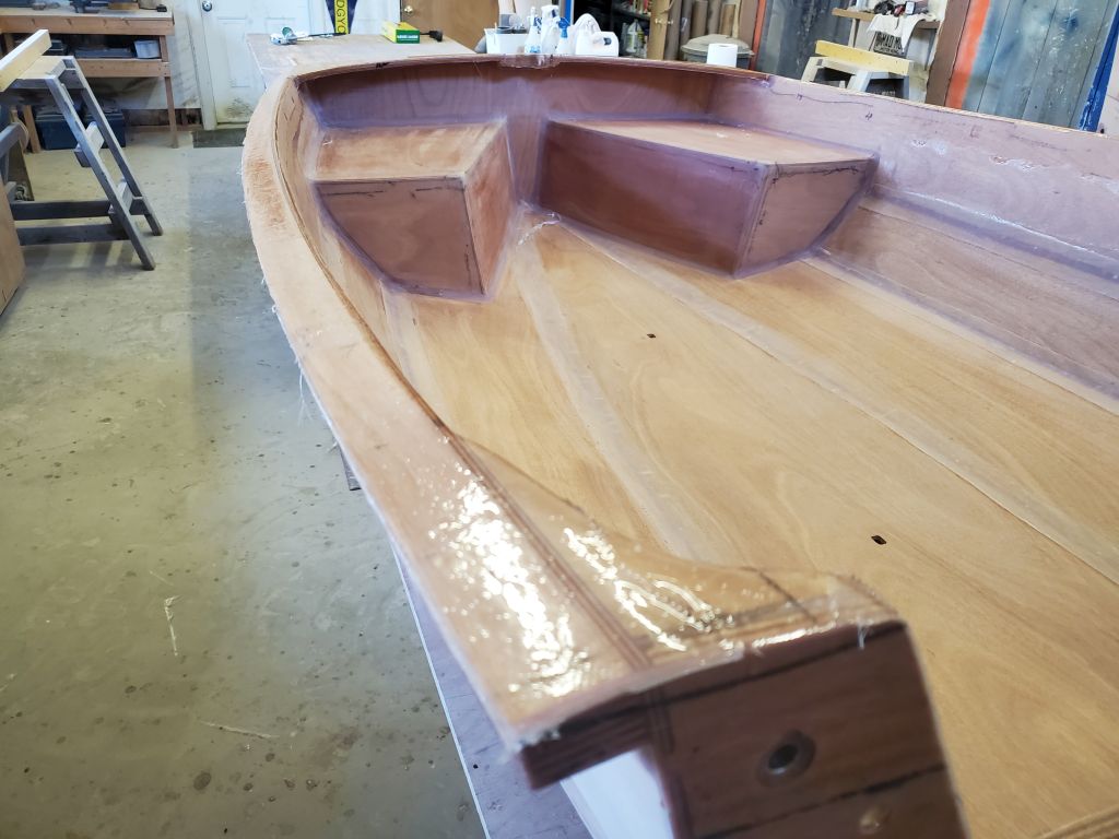
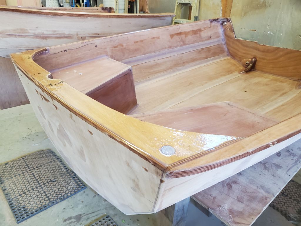
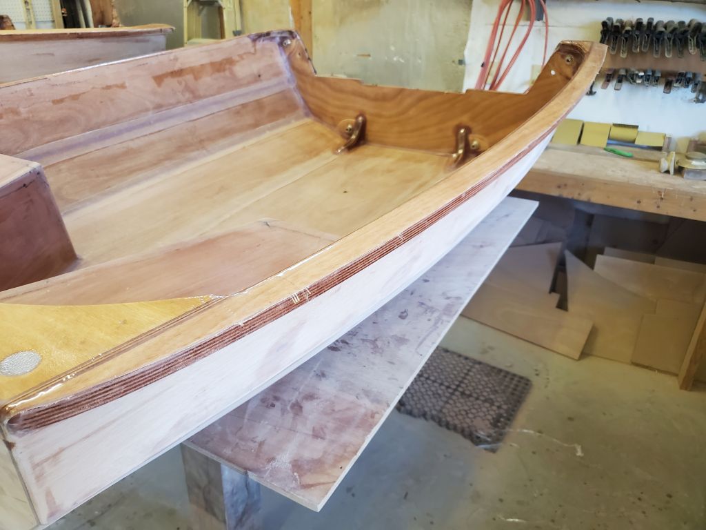
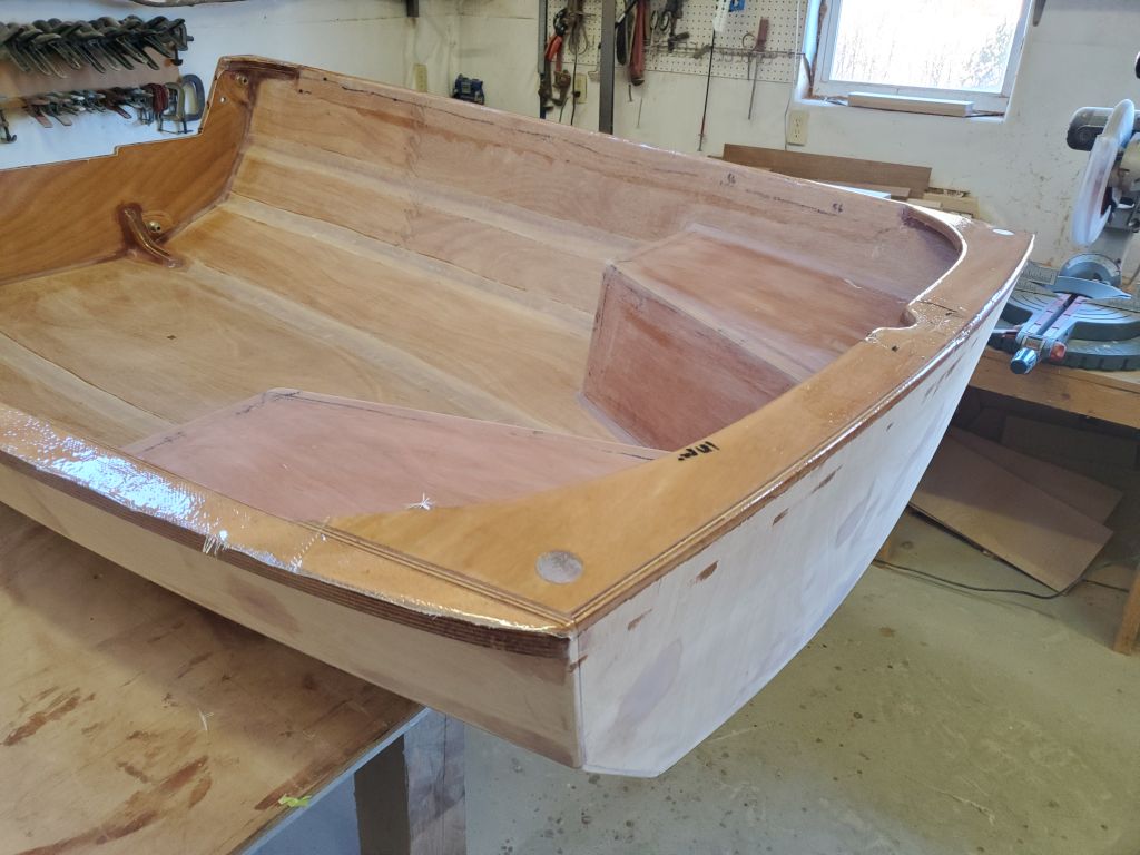
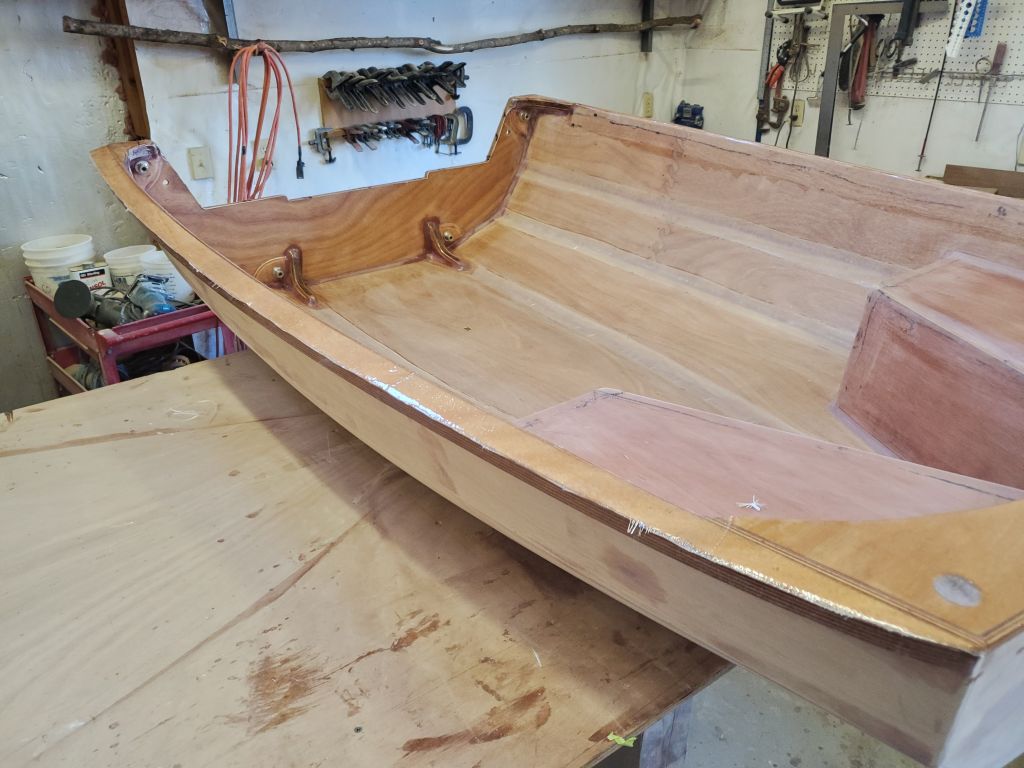
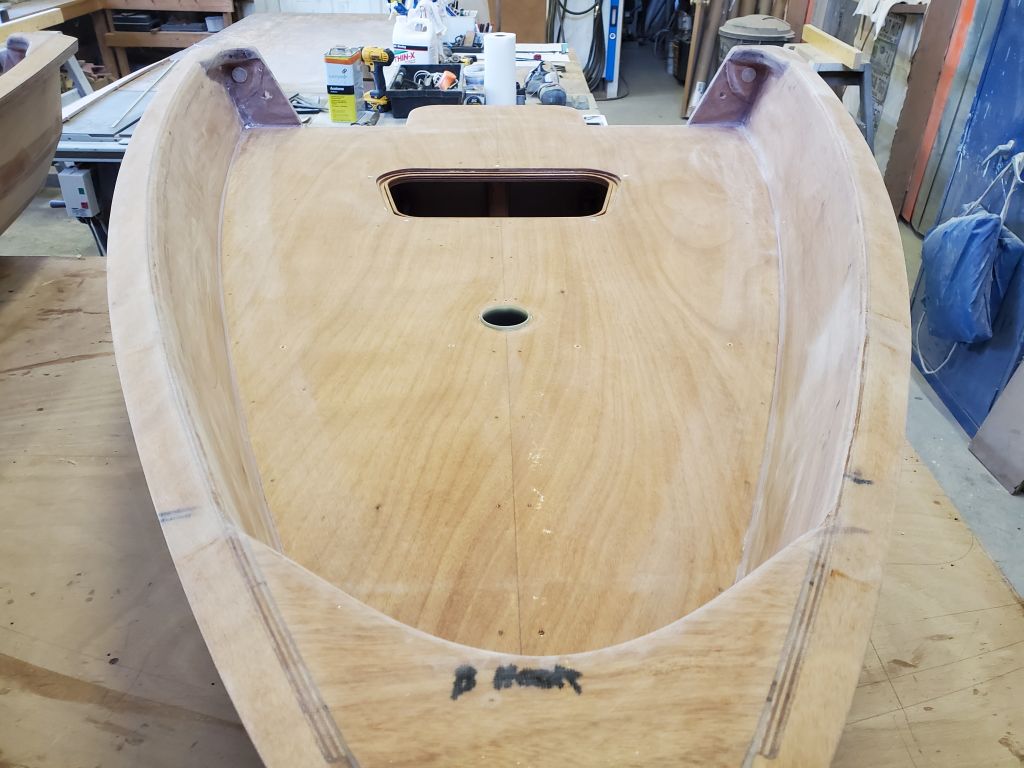
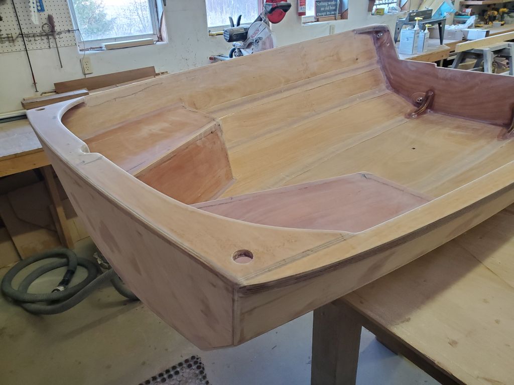
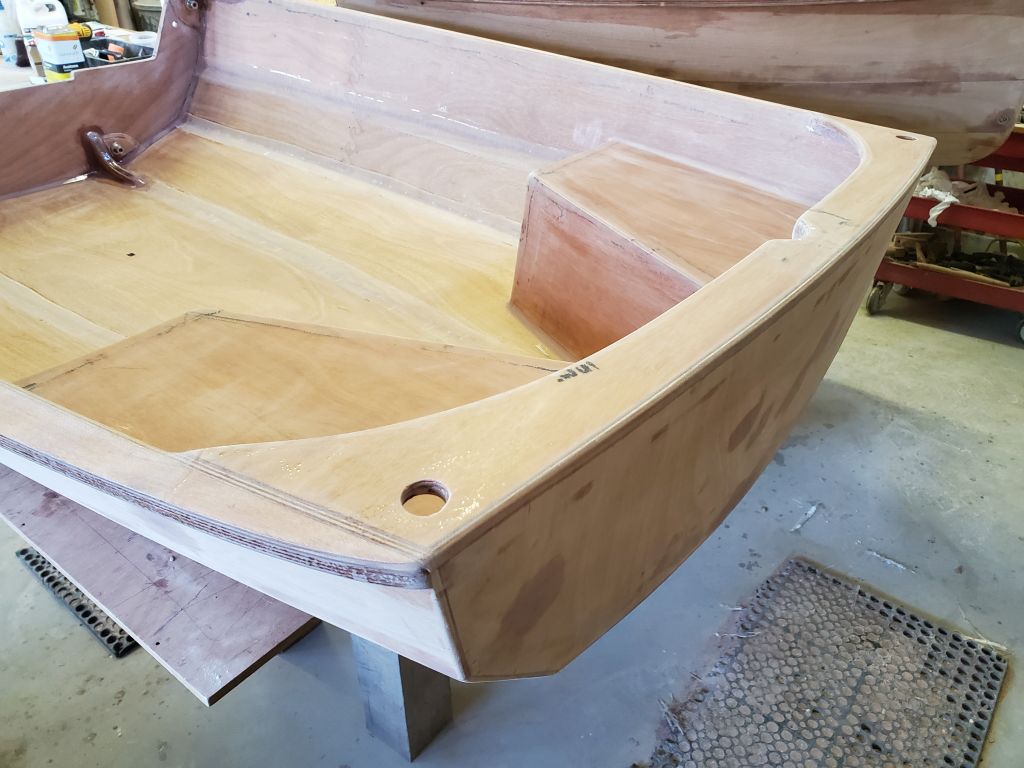
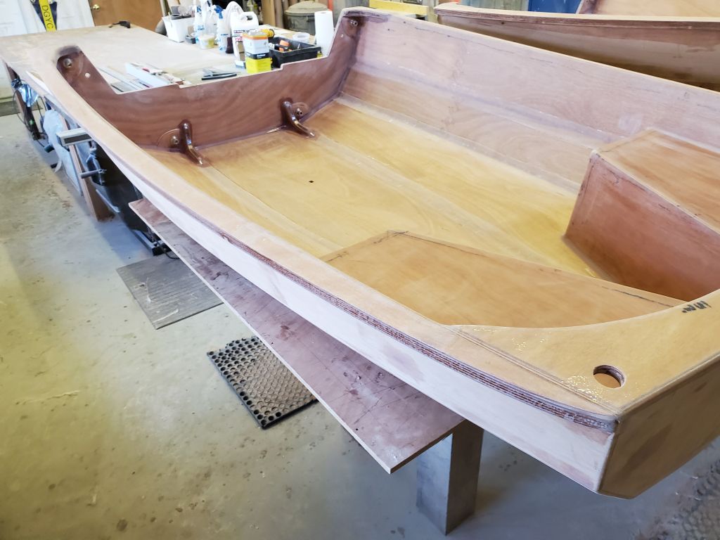
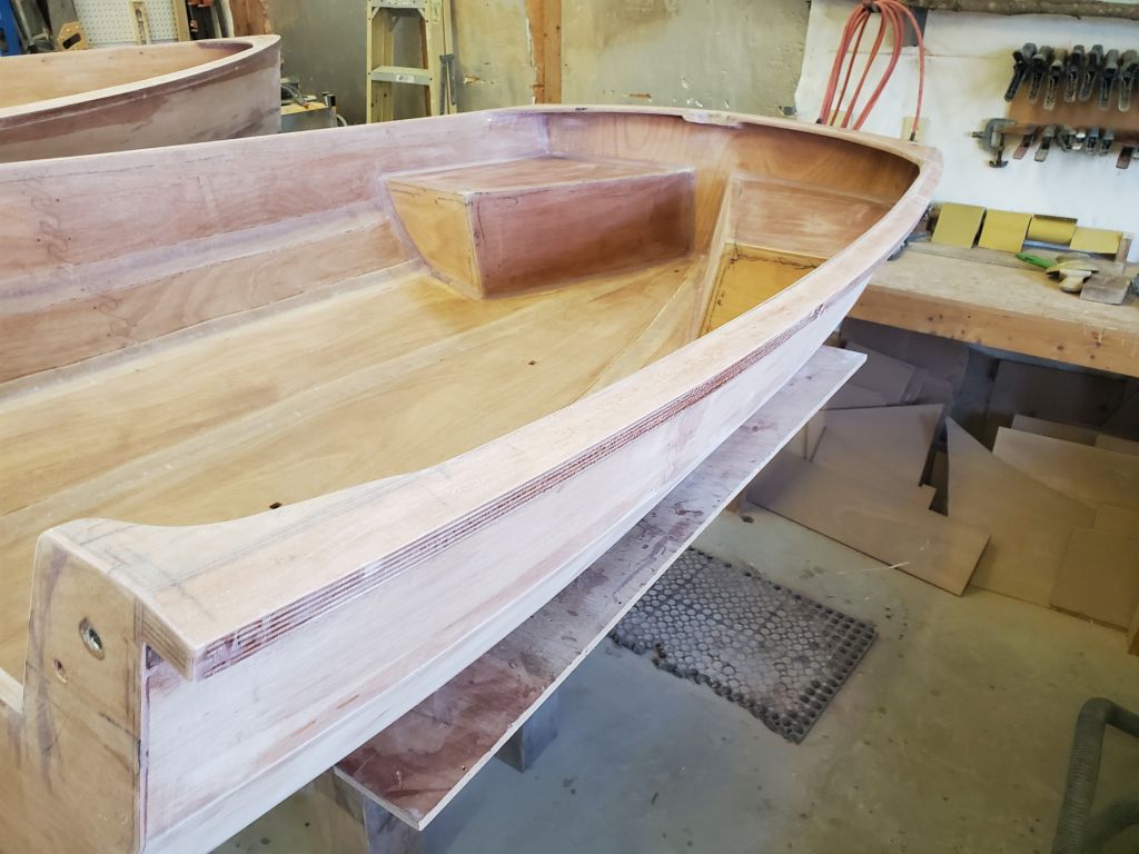
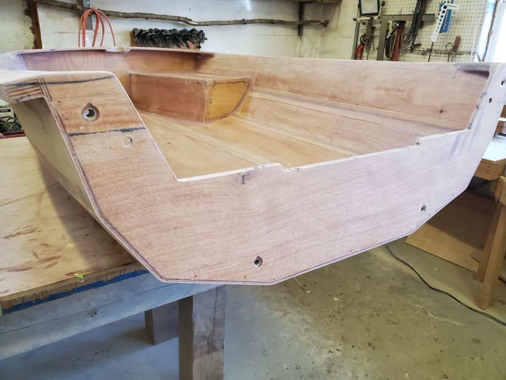
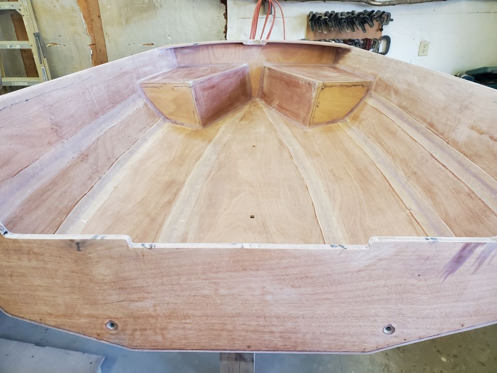
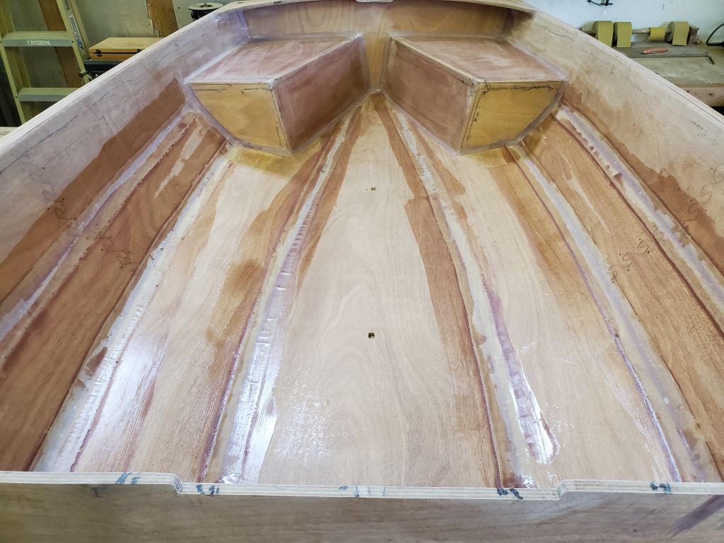
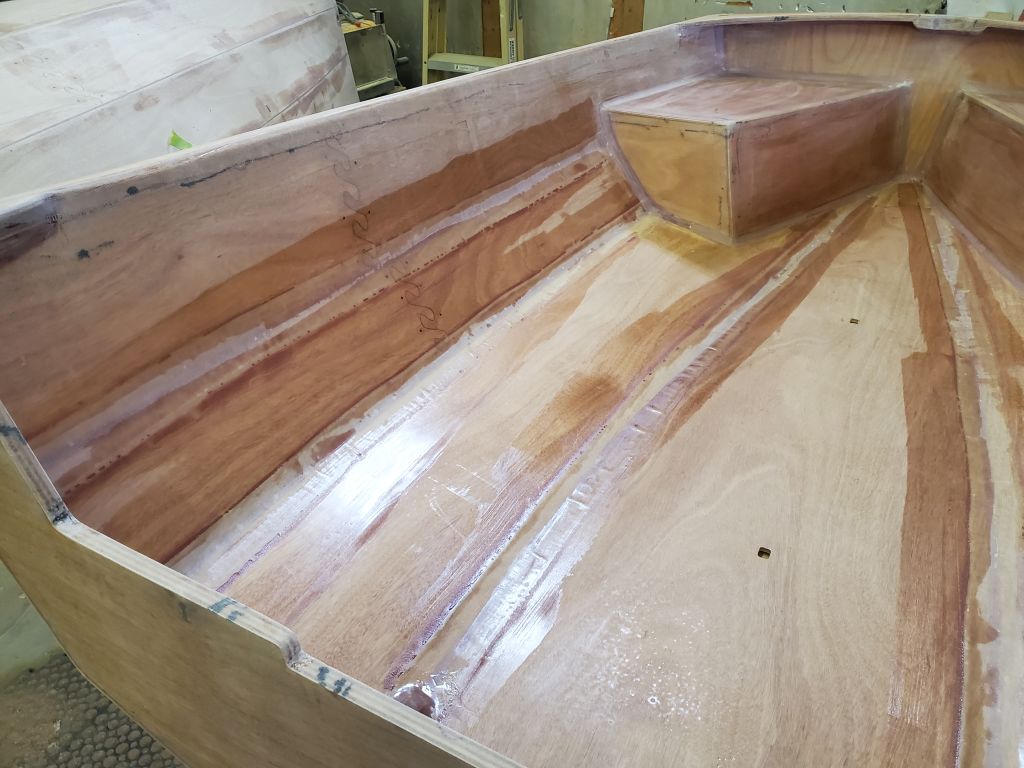
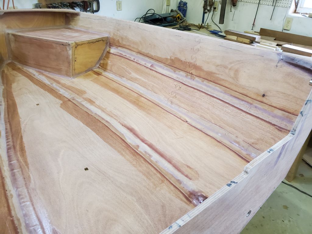
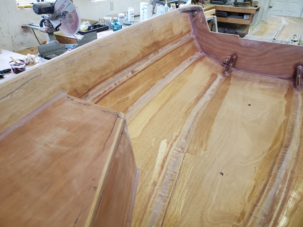
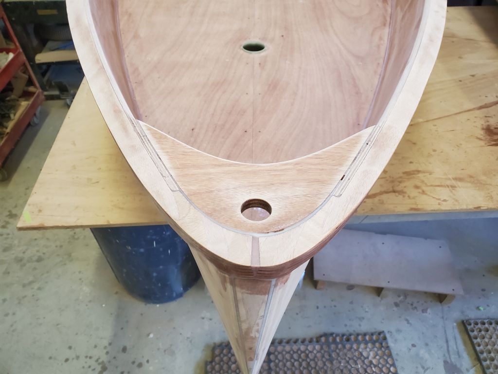
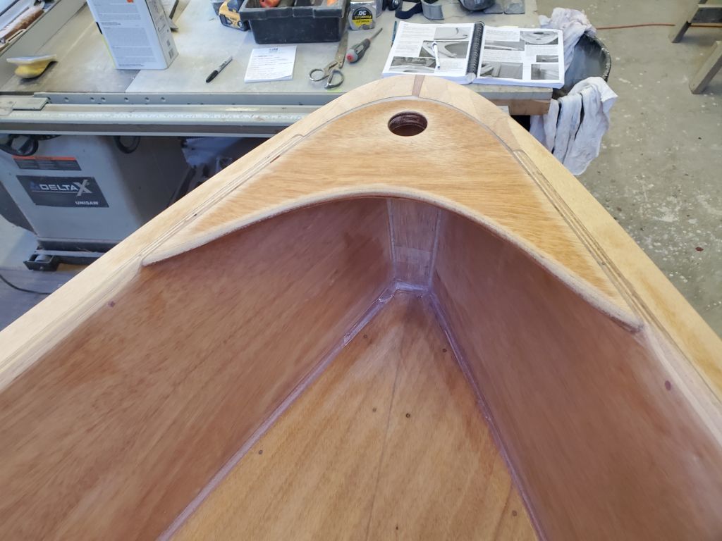
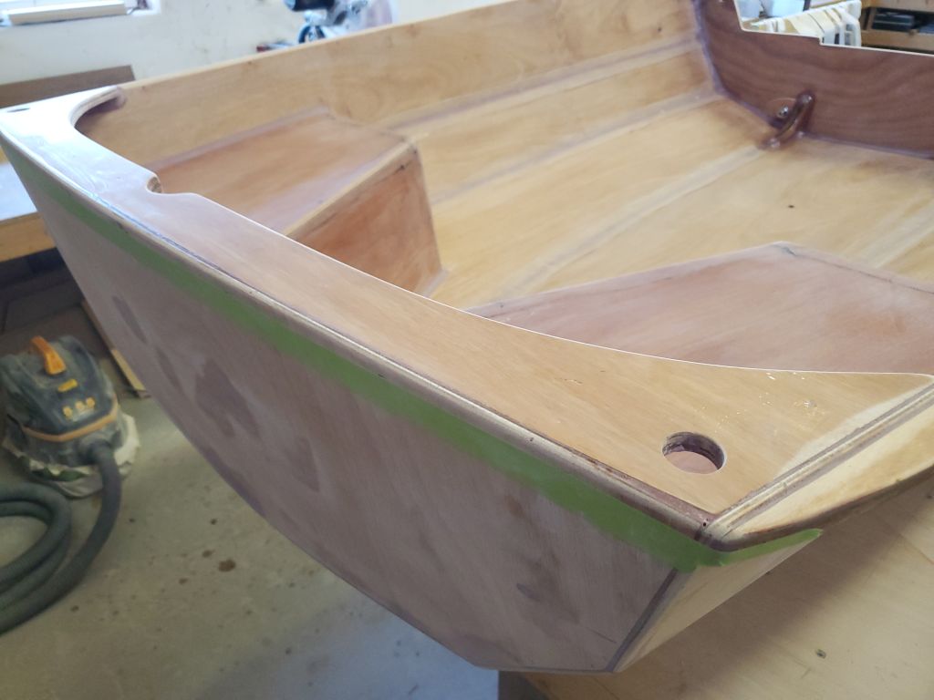
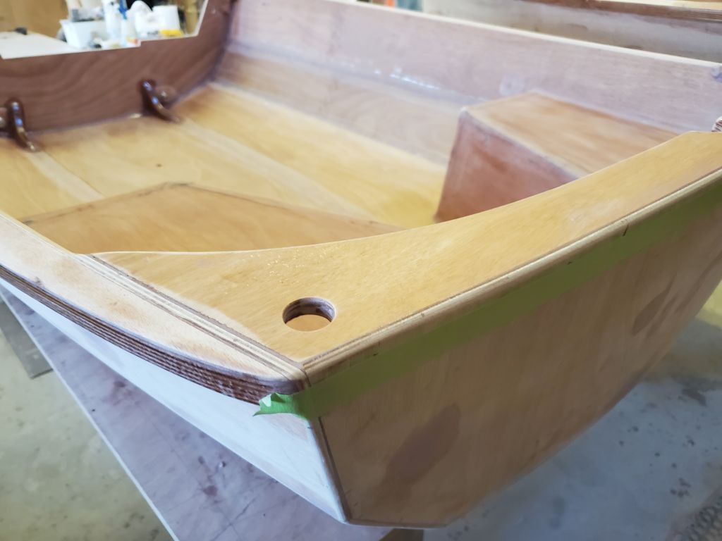
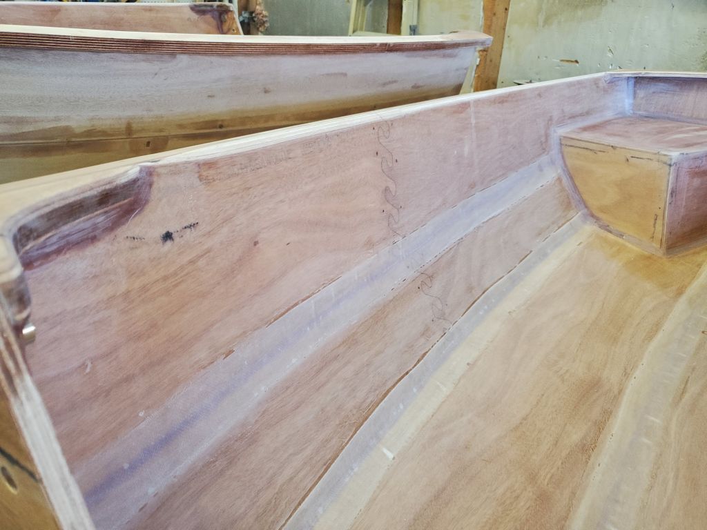
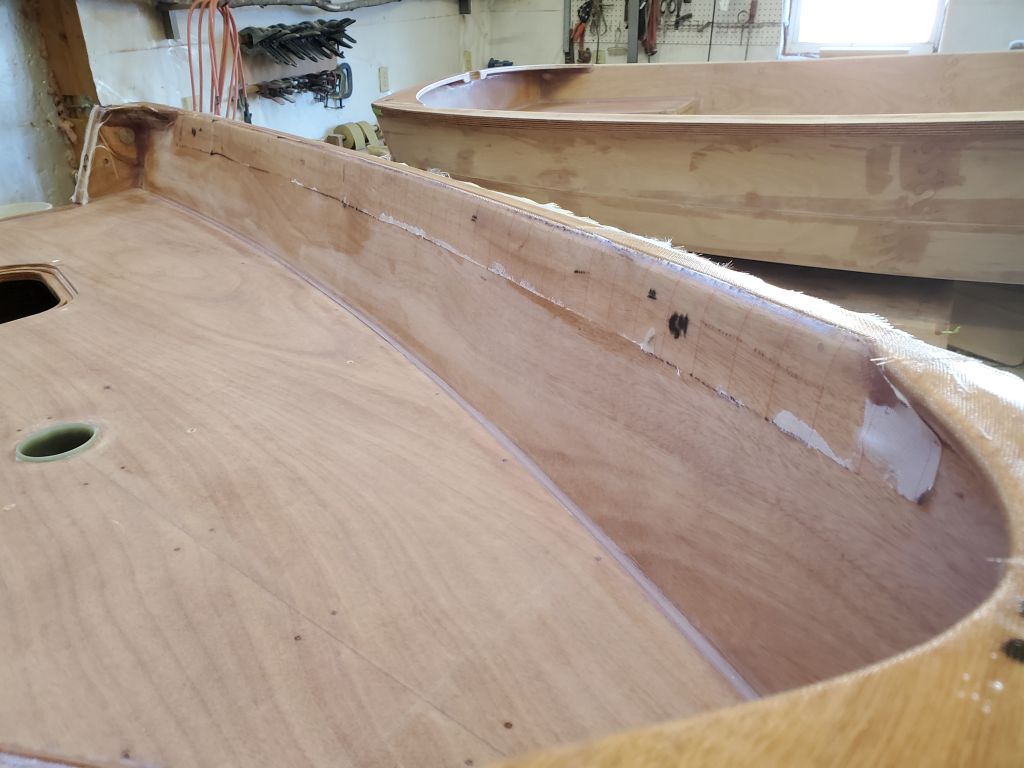
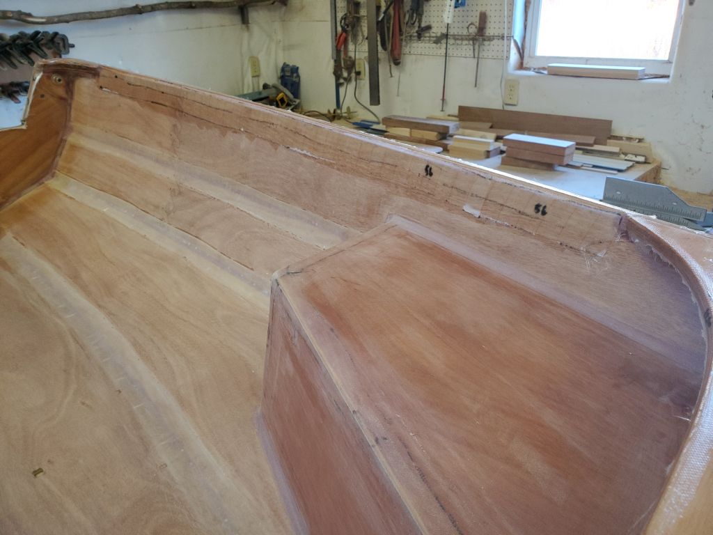
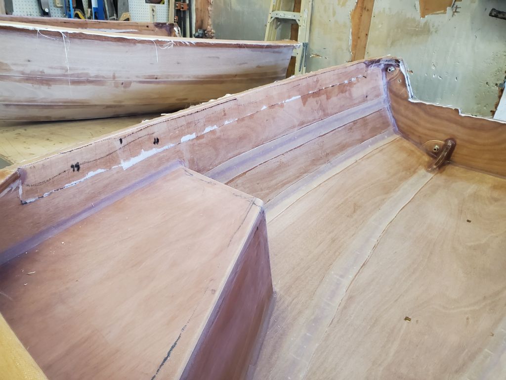
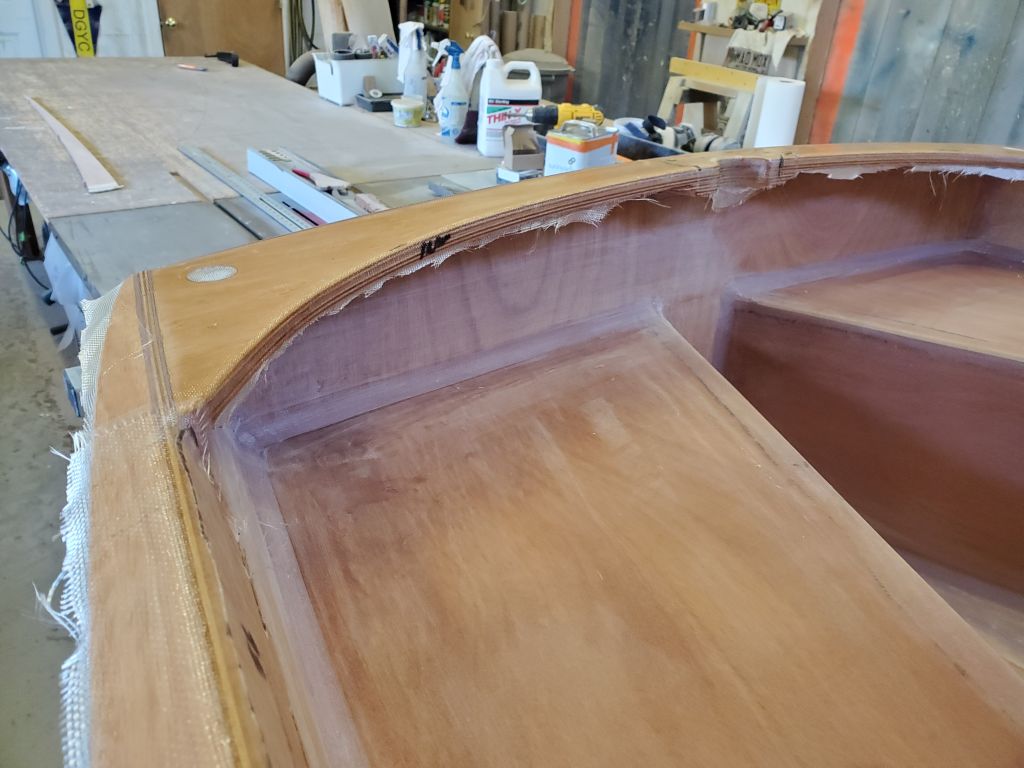
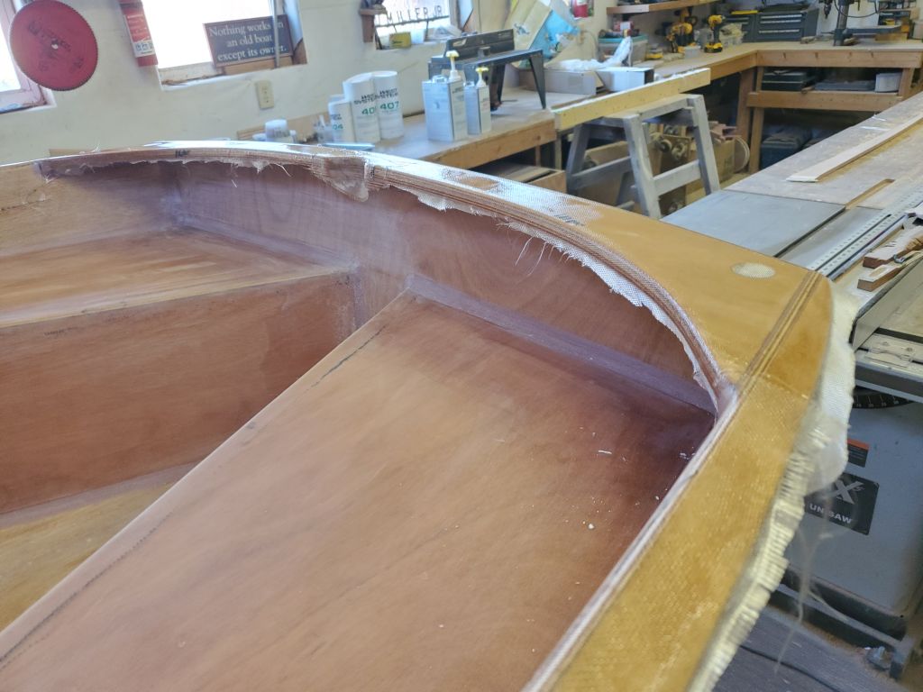
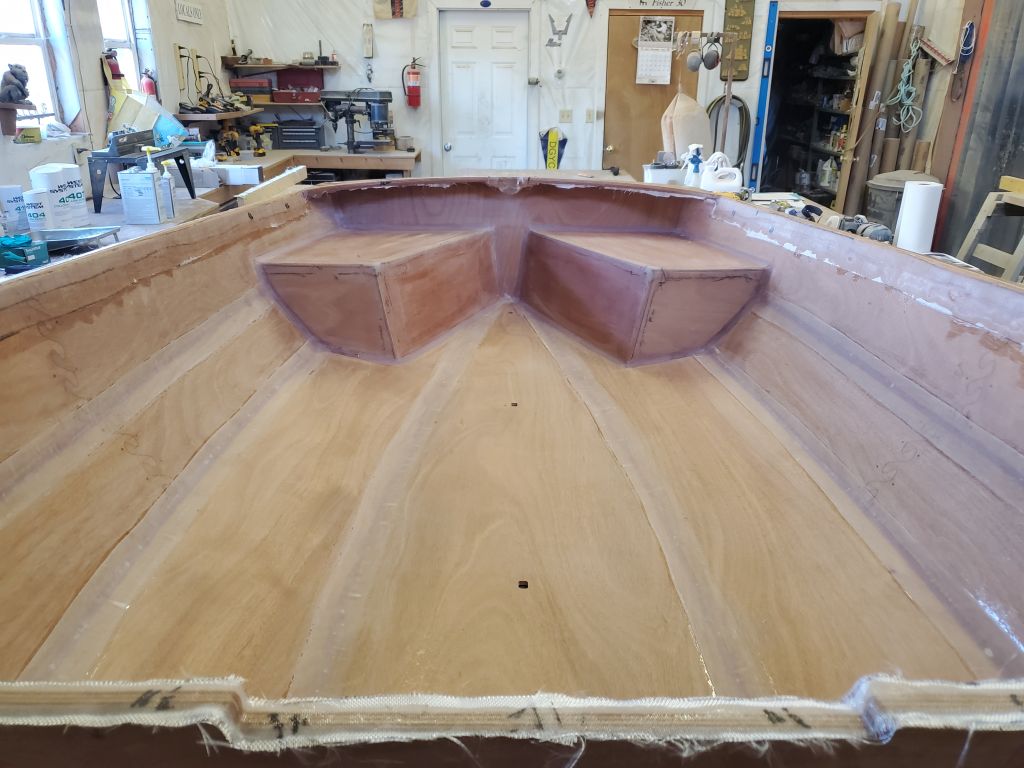
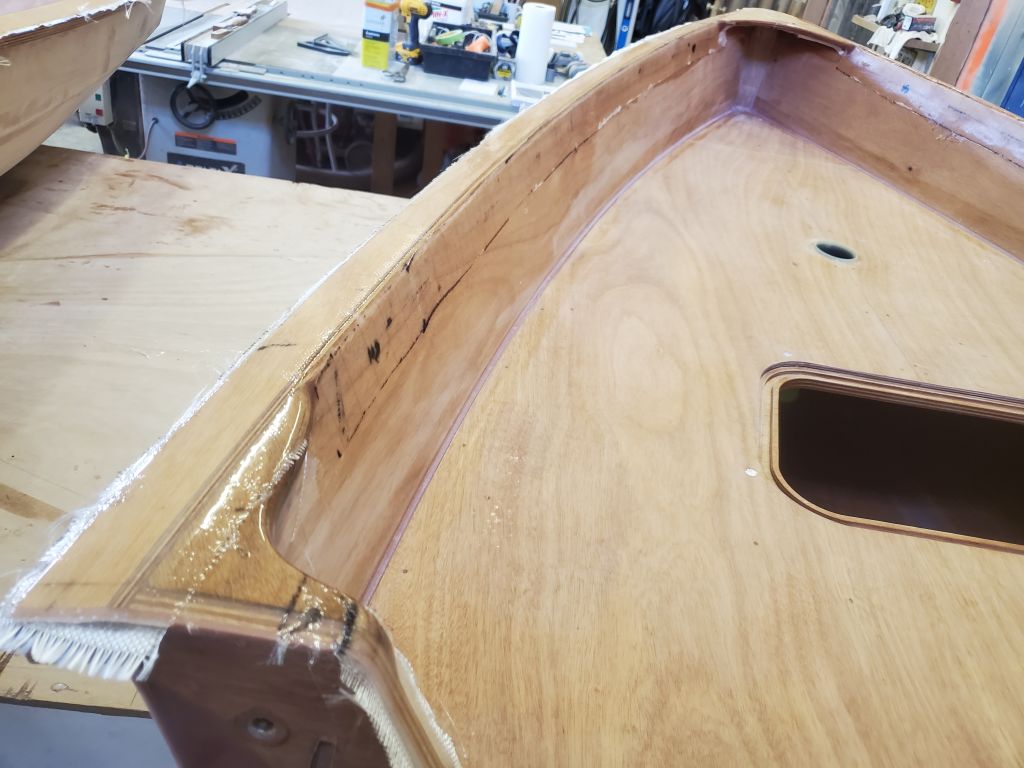
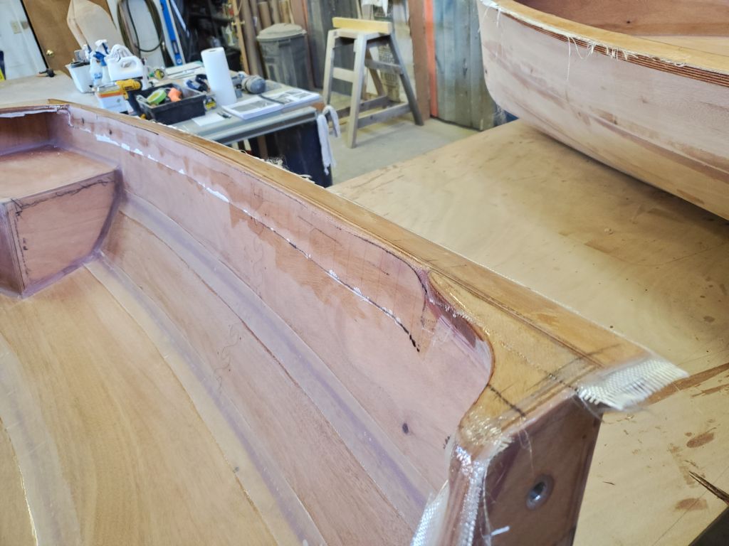
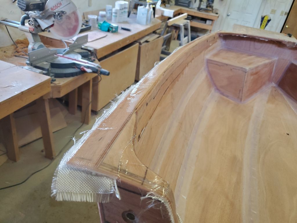
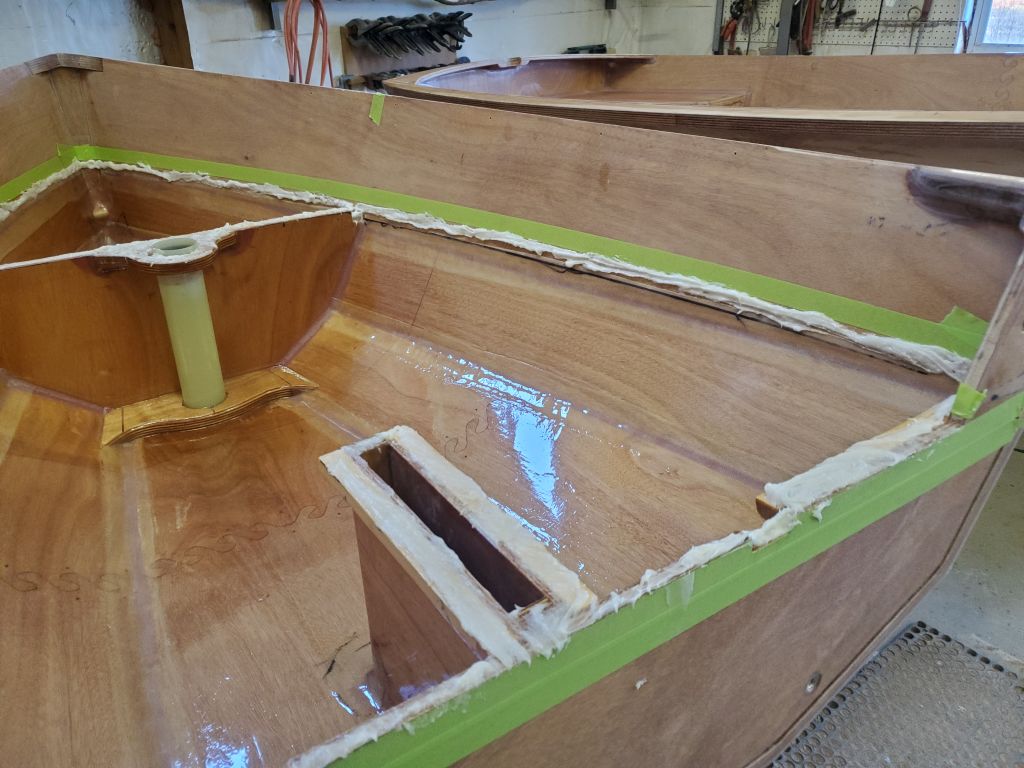
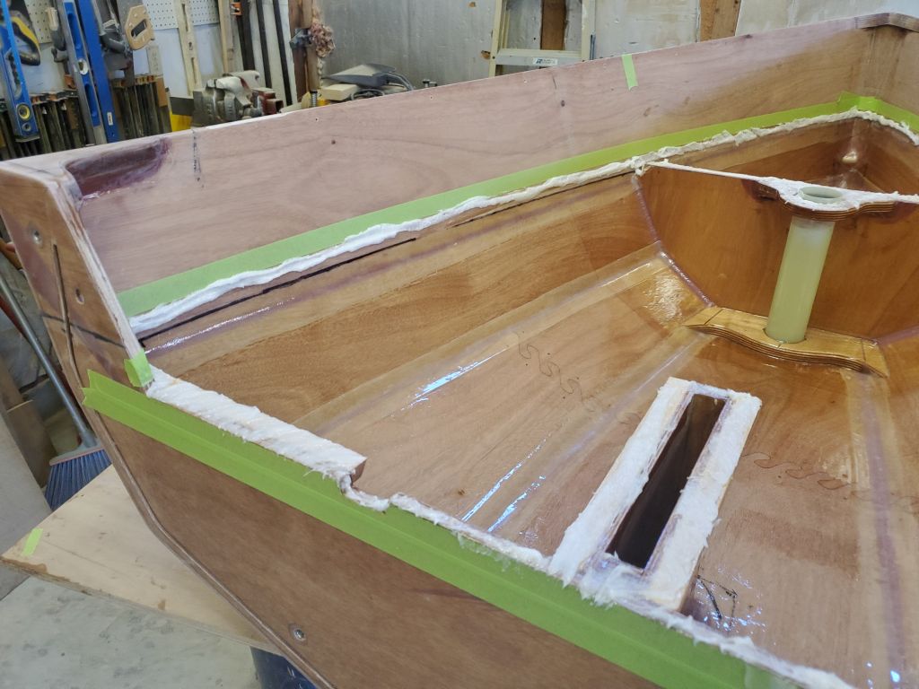
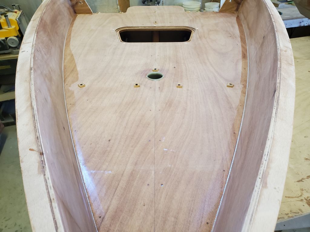
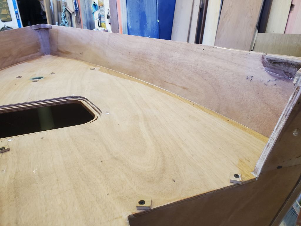
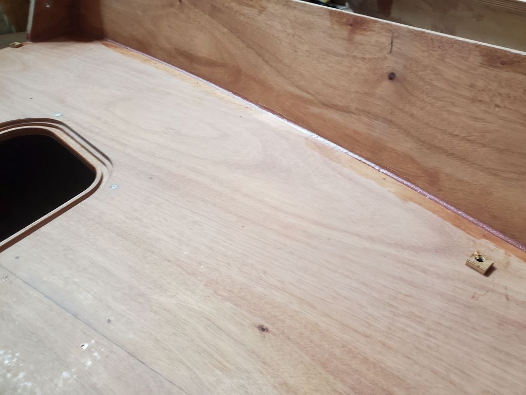
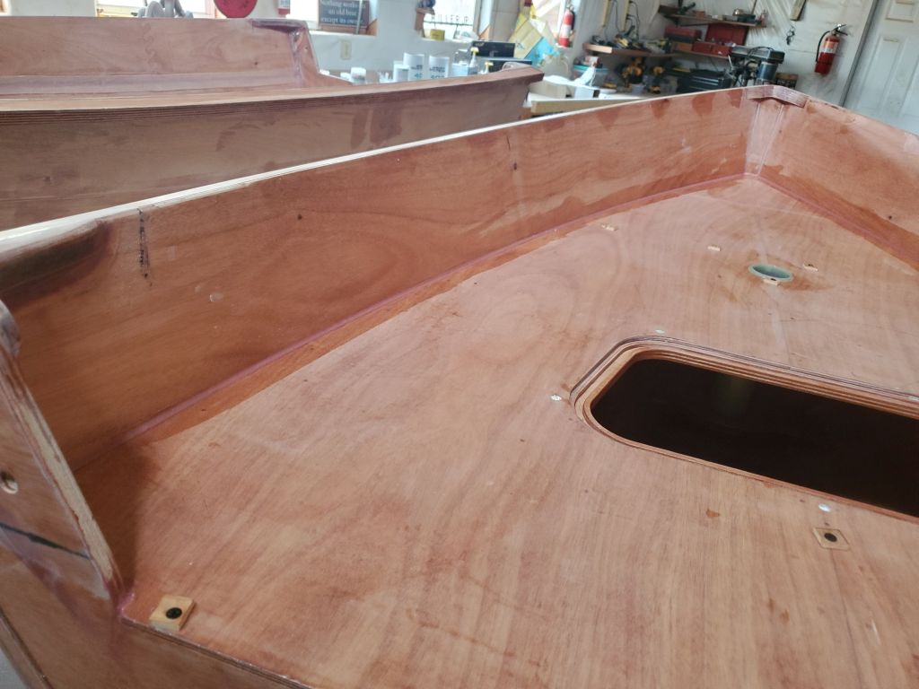
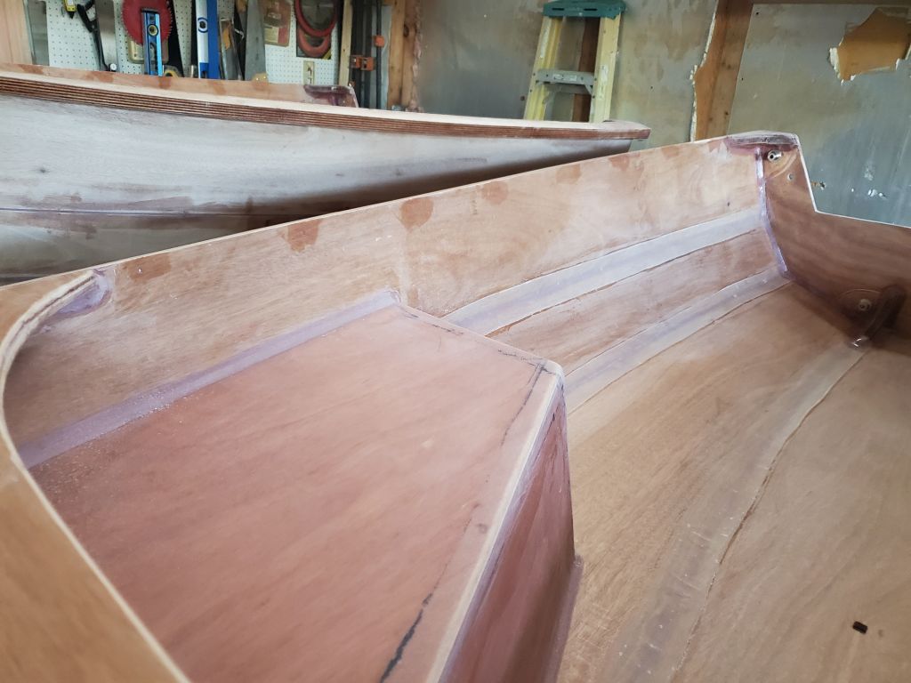
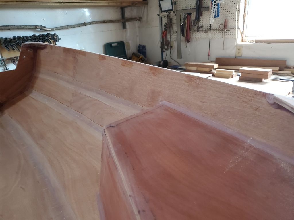
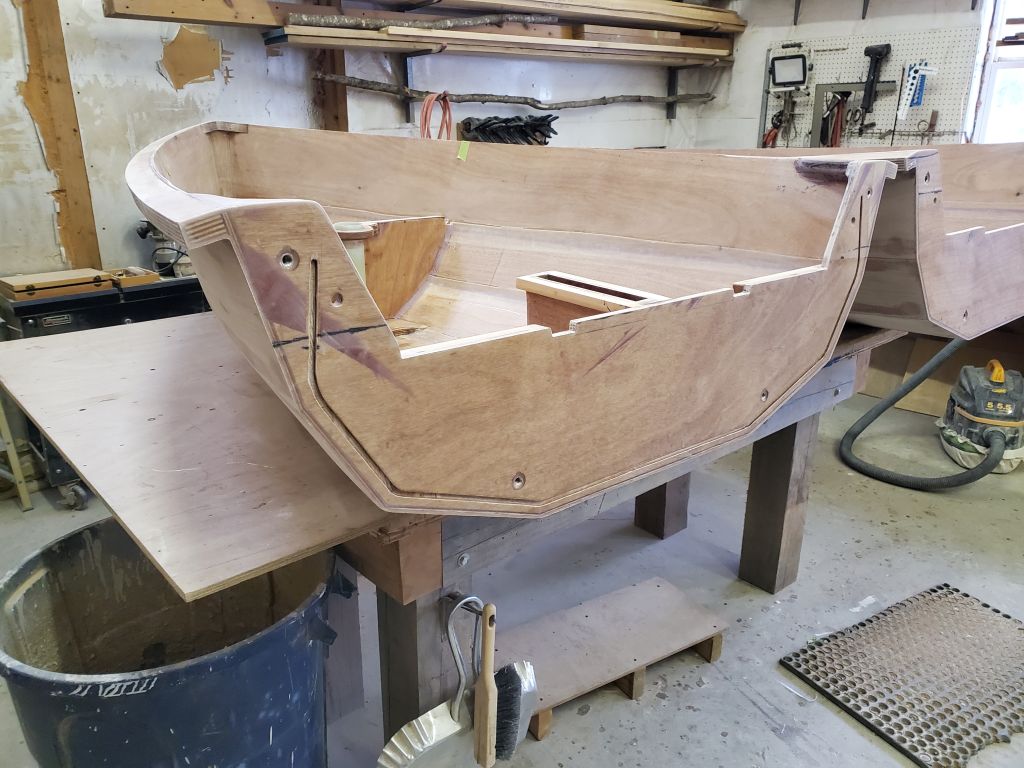
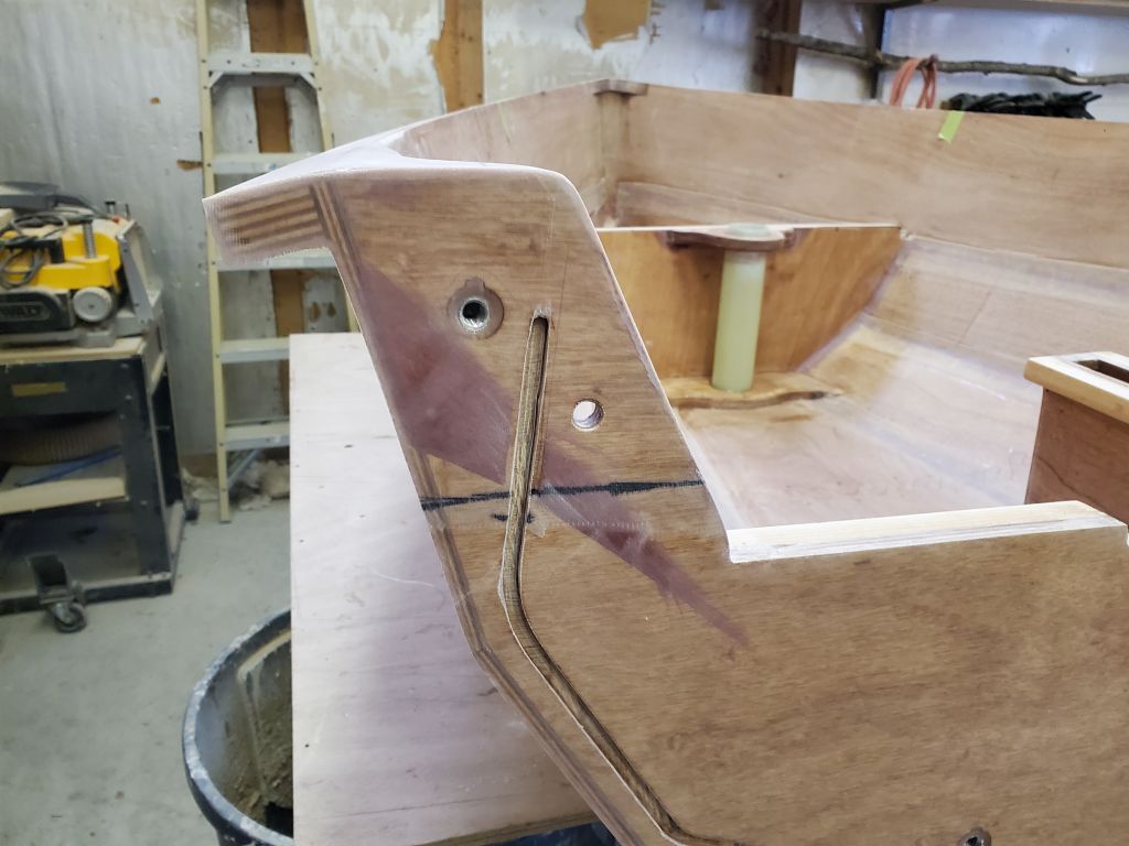
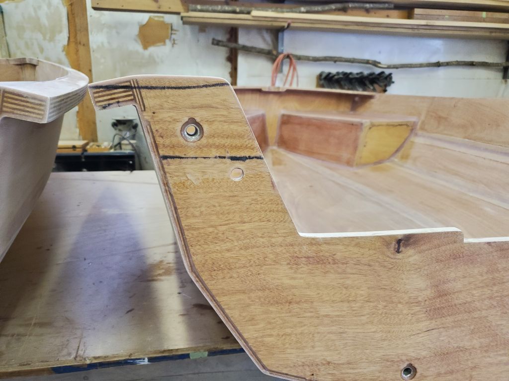
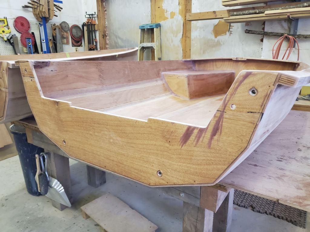
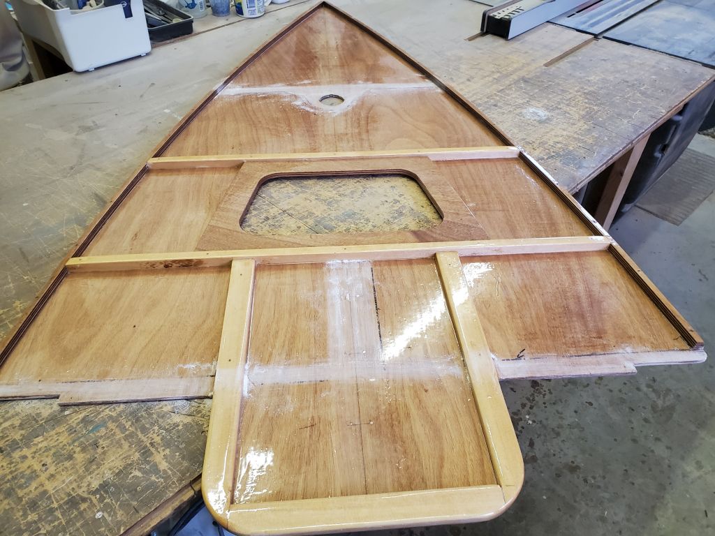
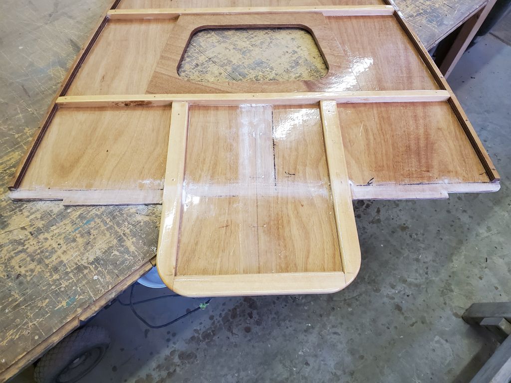
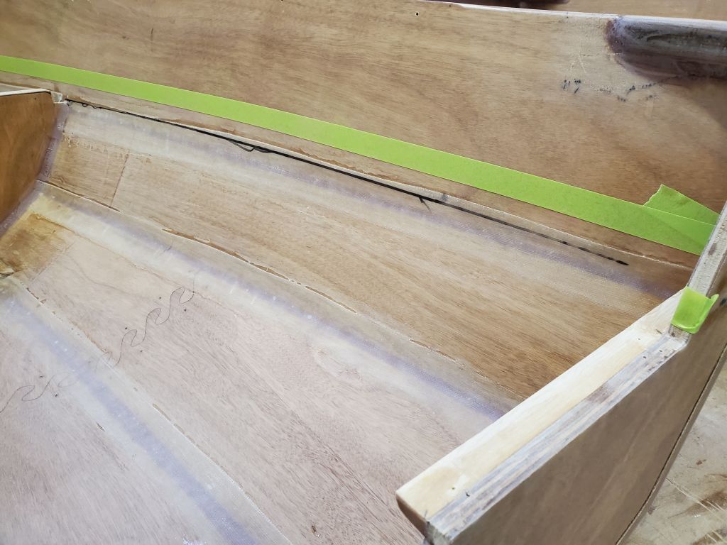
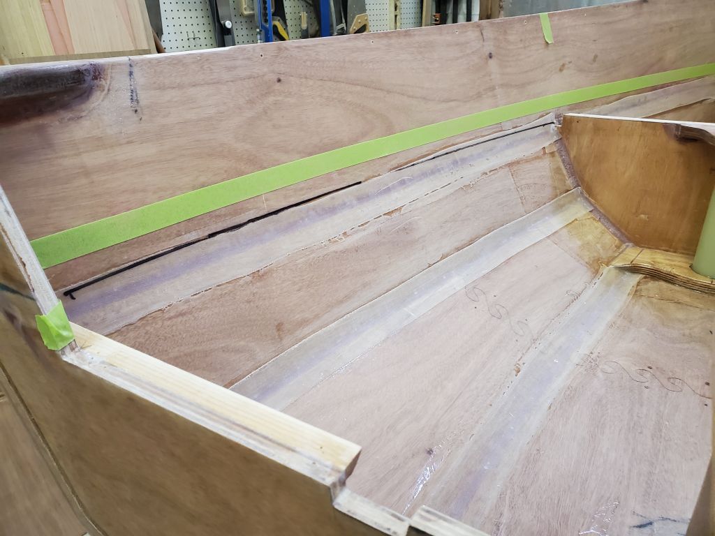
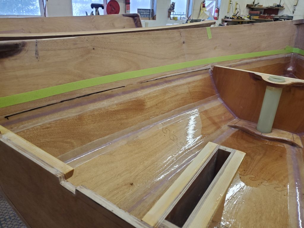
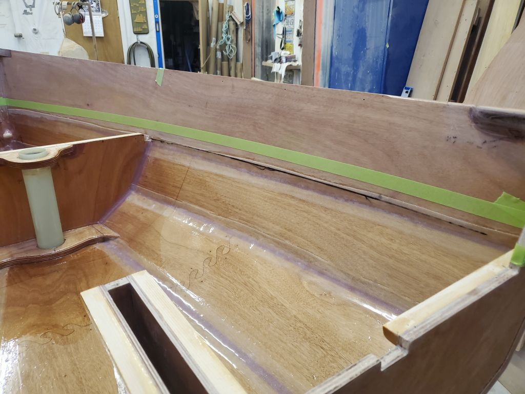
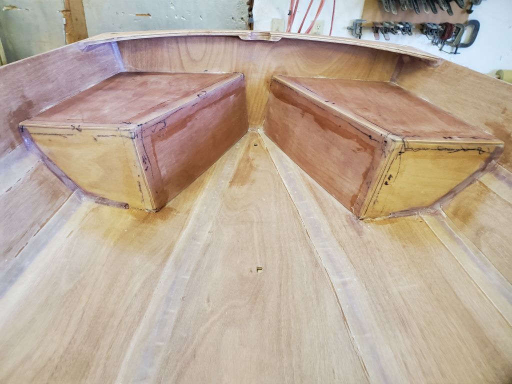
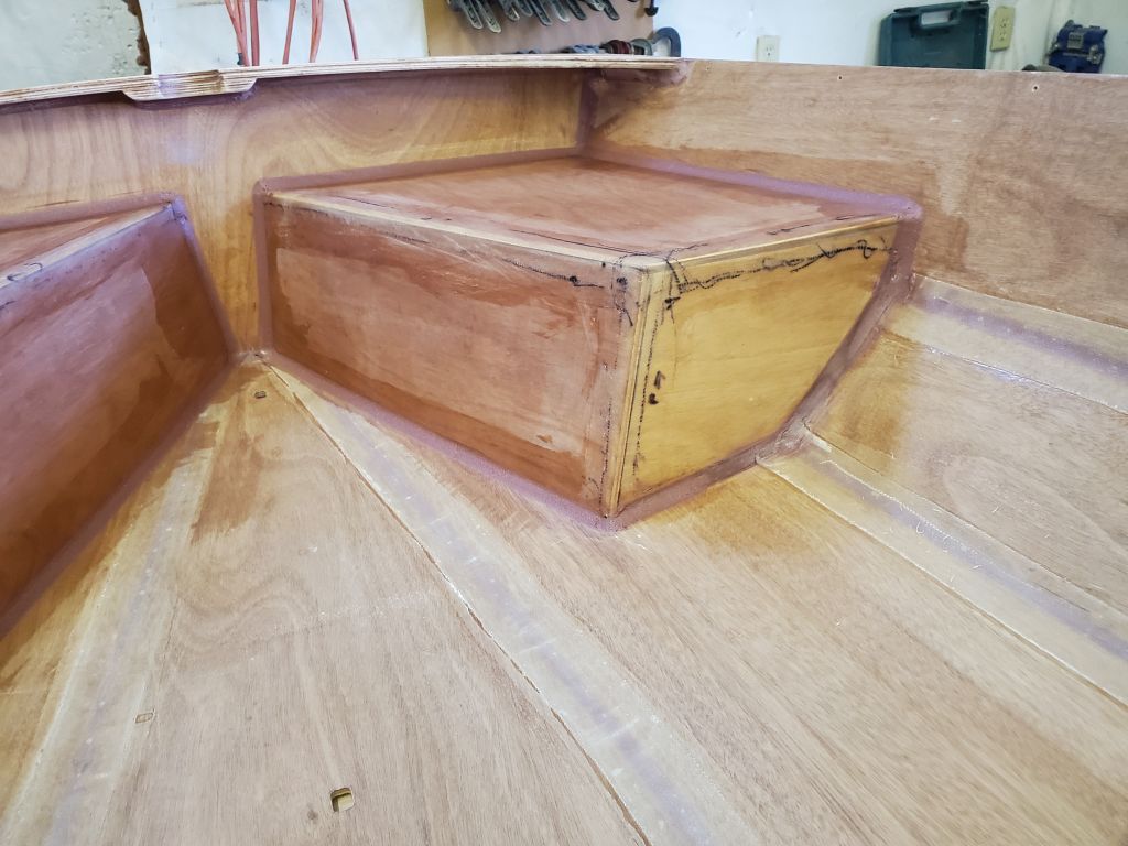
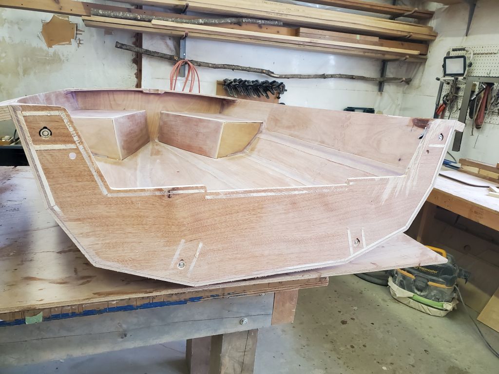
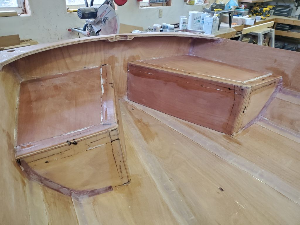
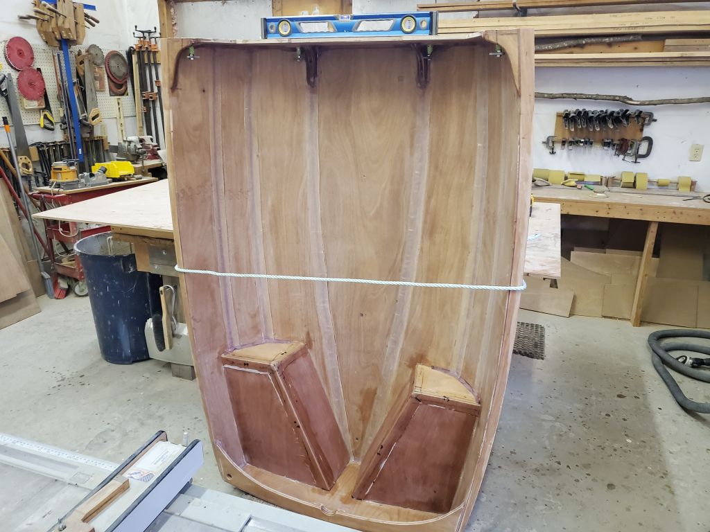
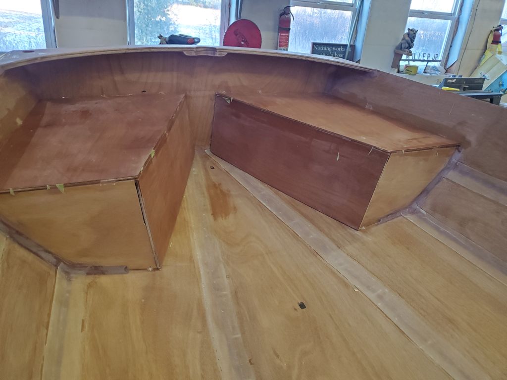
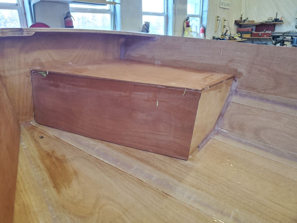
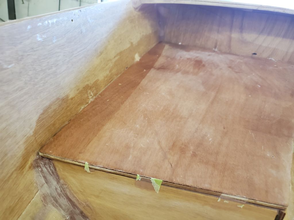
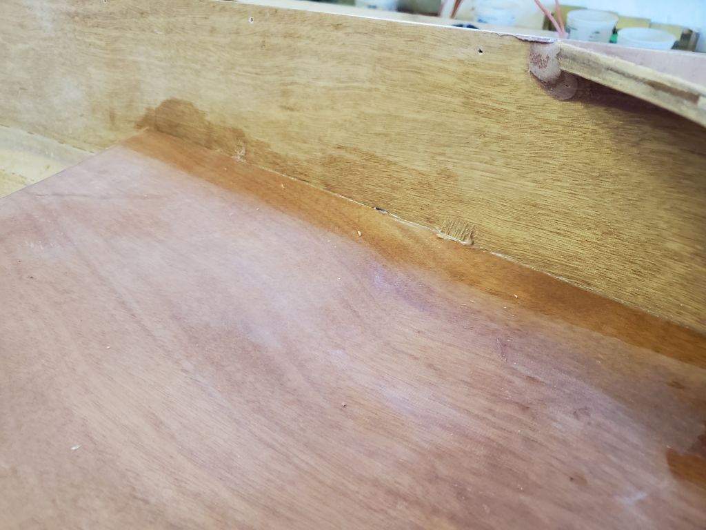
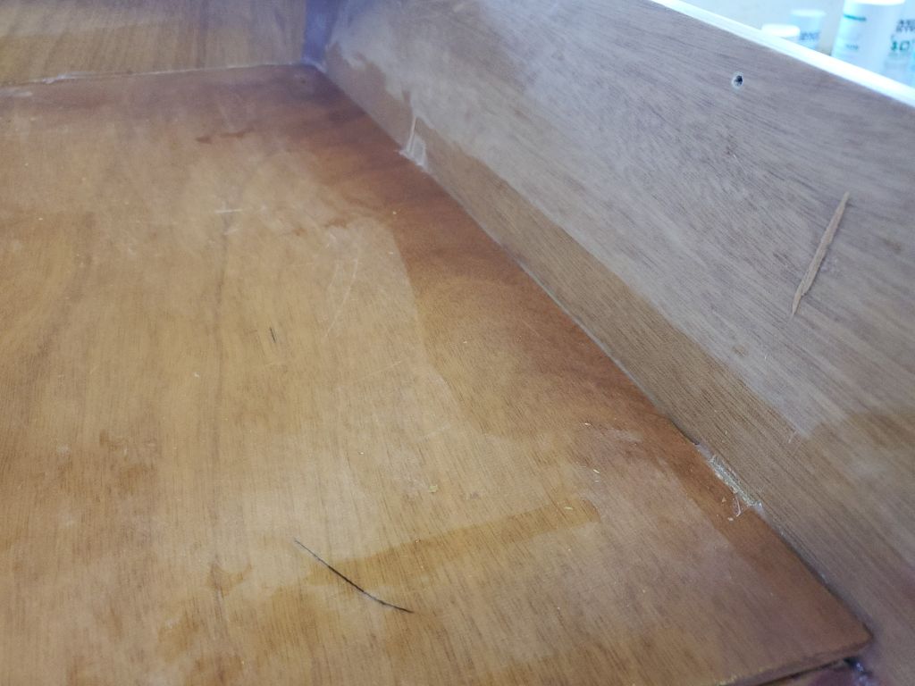
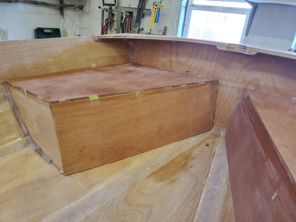
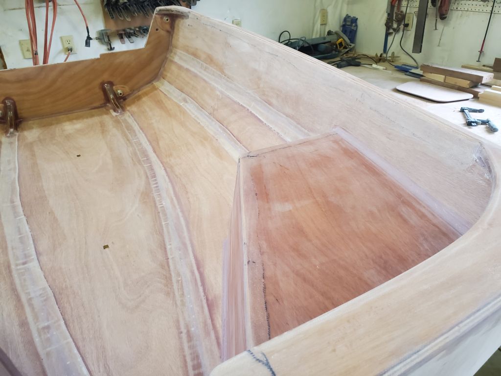
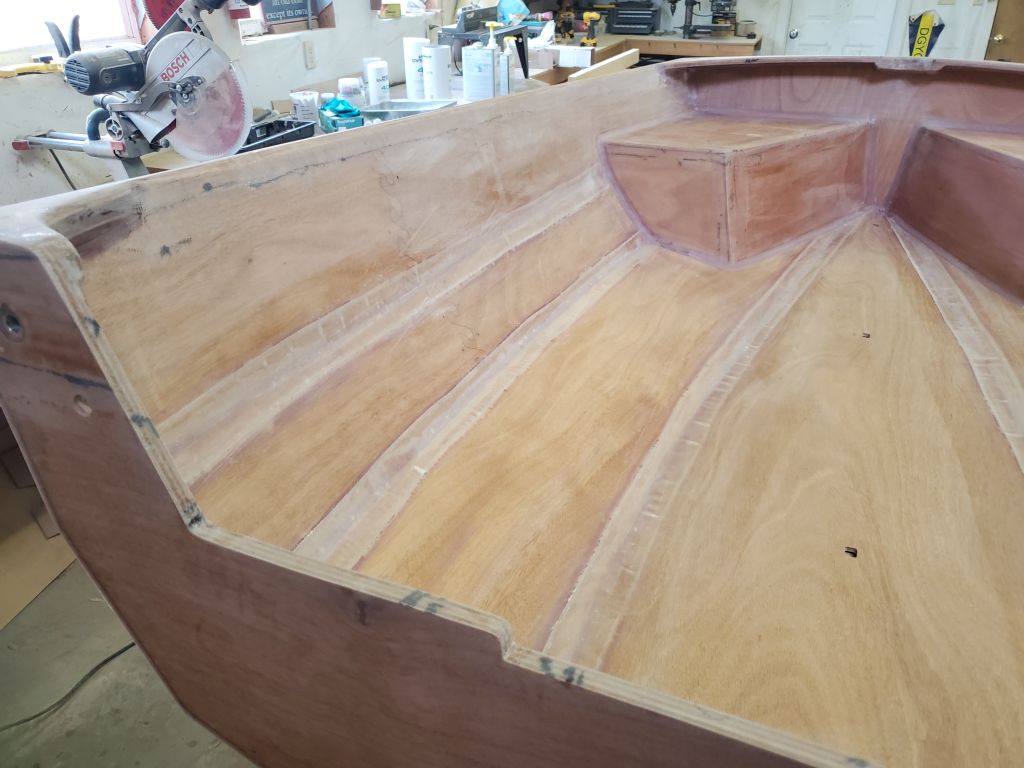
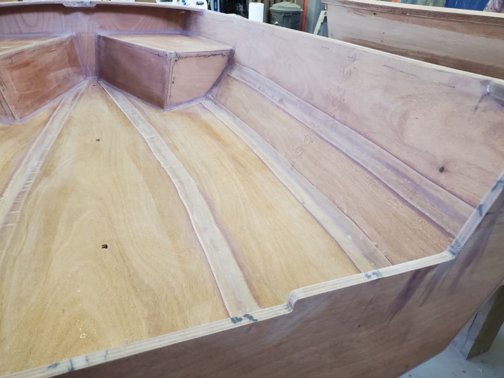
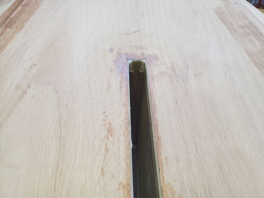
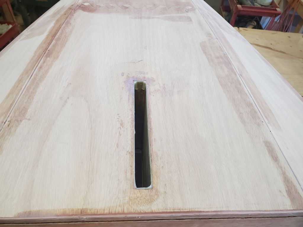
I got a late start on the day after an offsite appointment, but my first task was to lightly sand the interior of the stern half to finish off the minor fairing work.
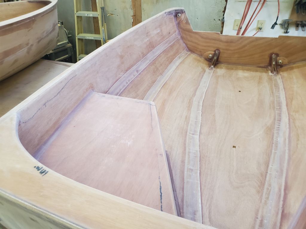
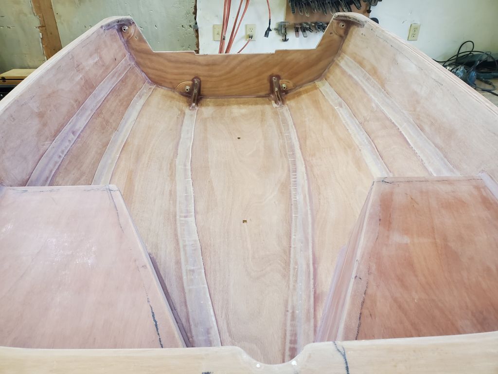
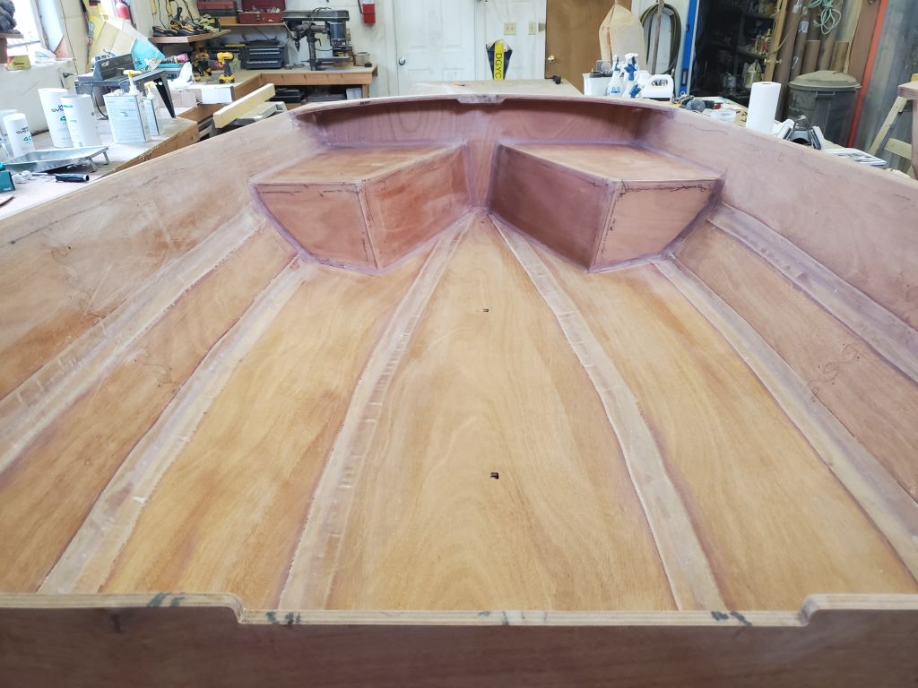
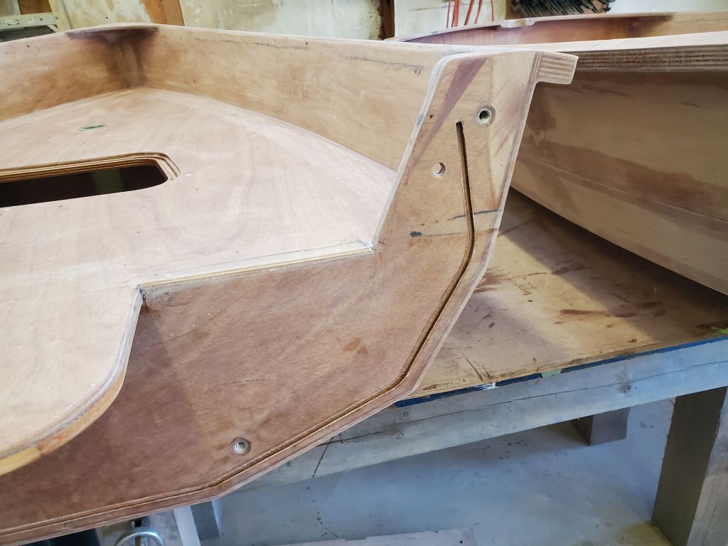
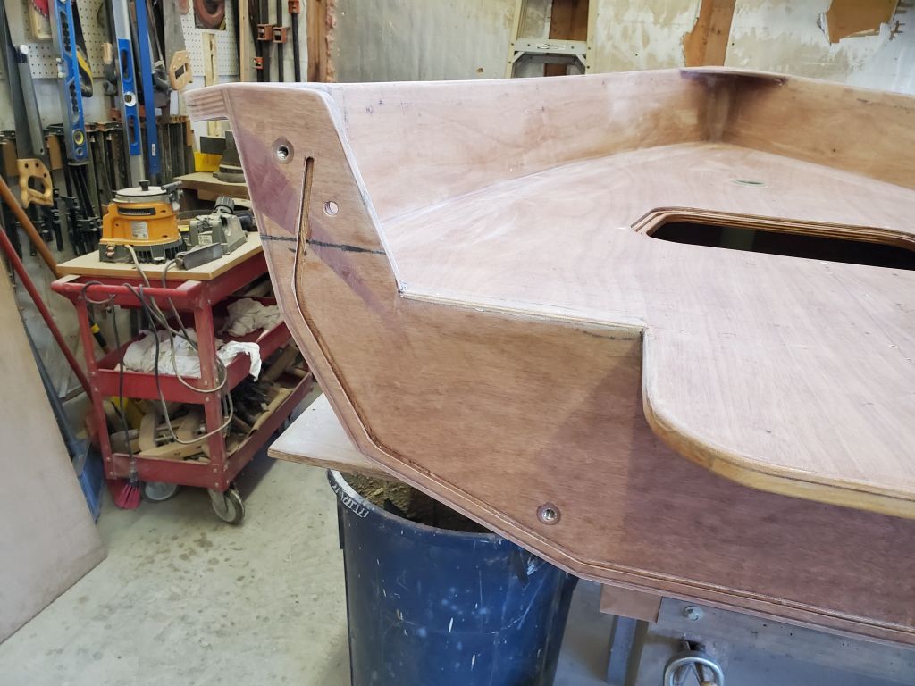
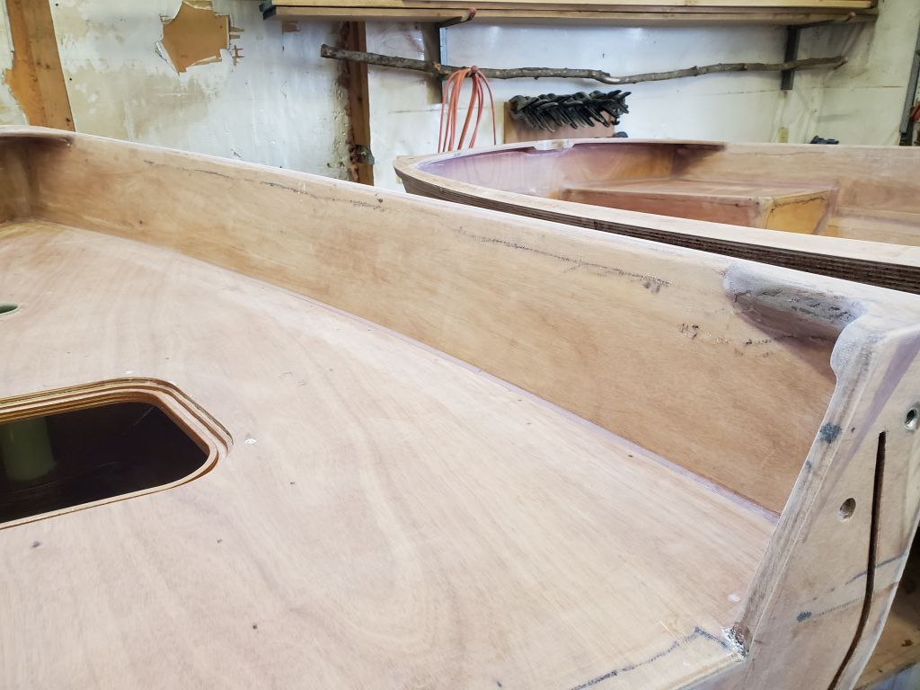
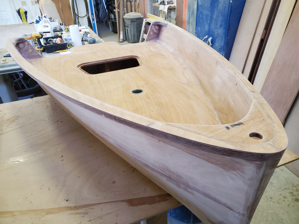
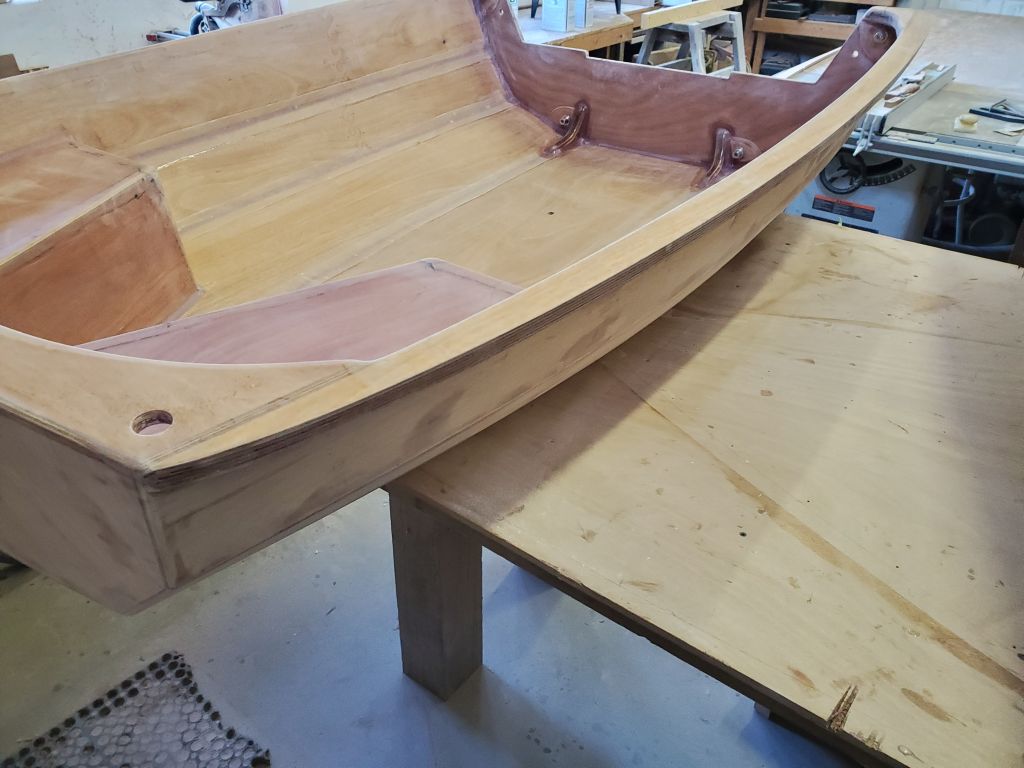
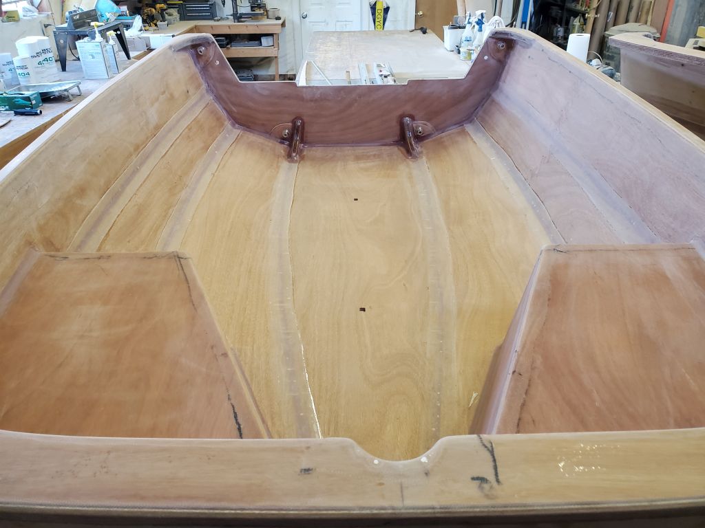
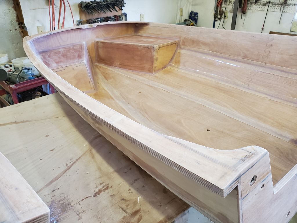
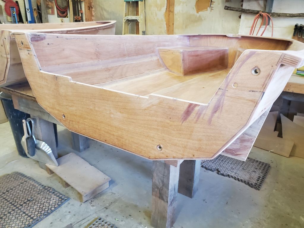
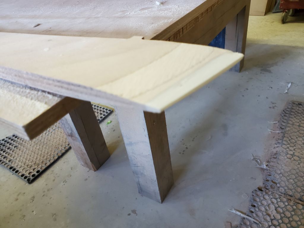
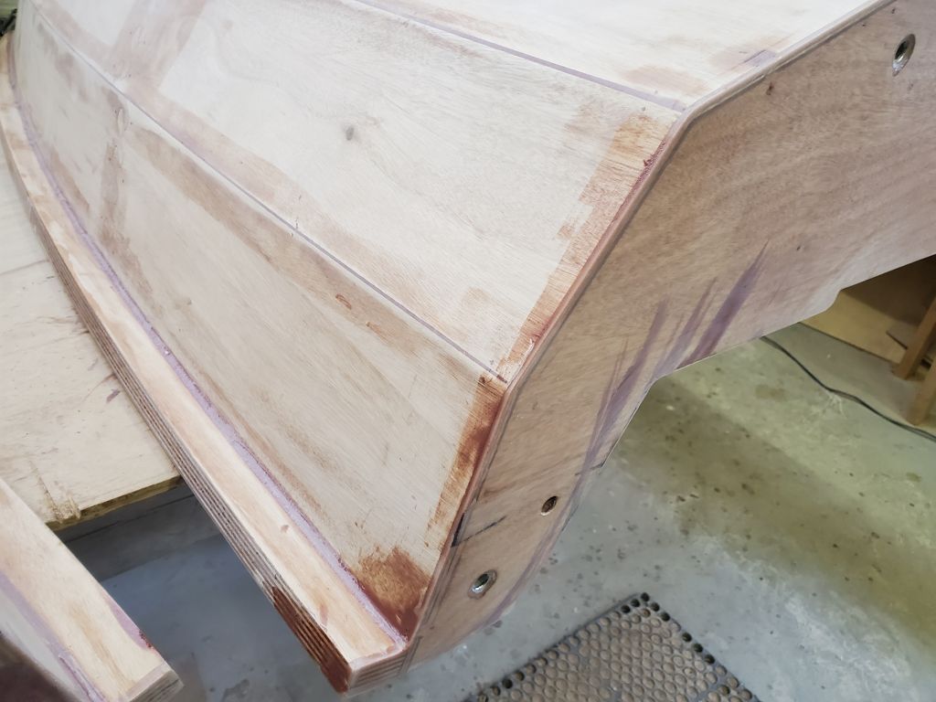
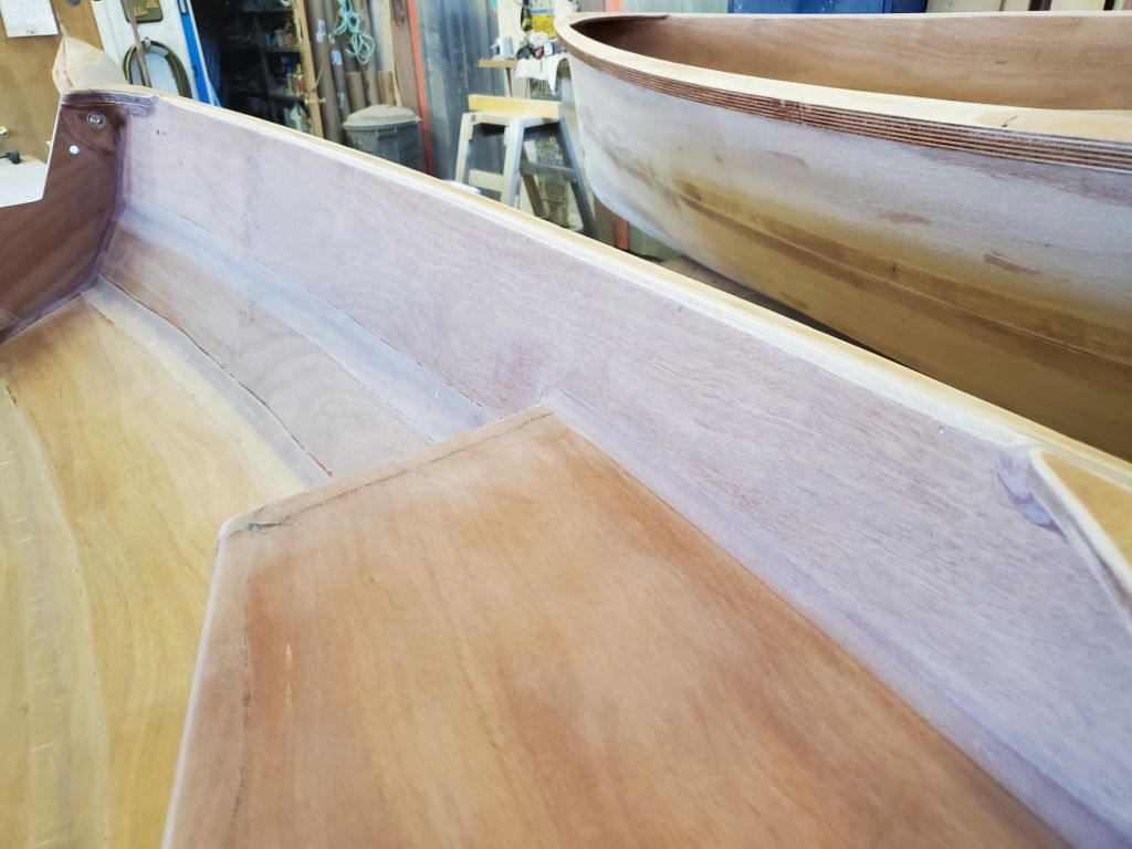
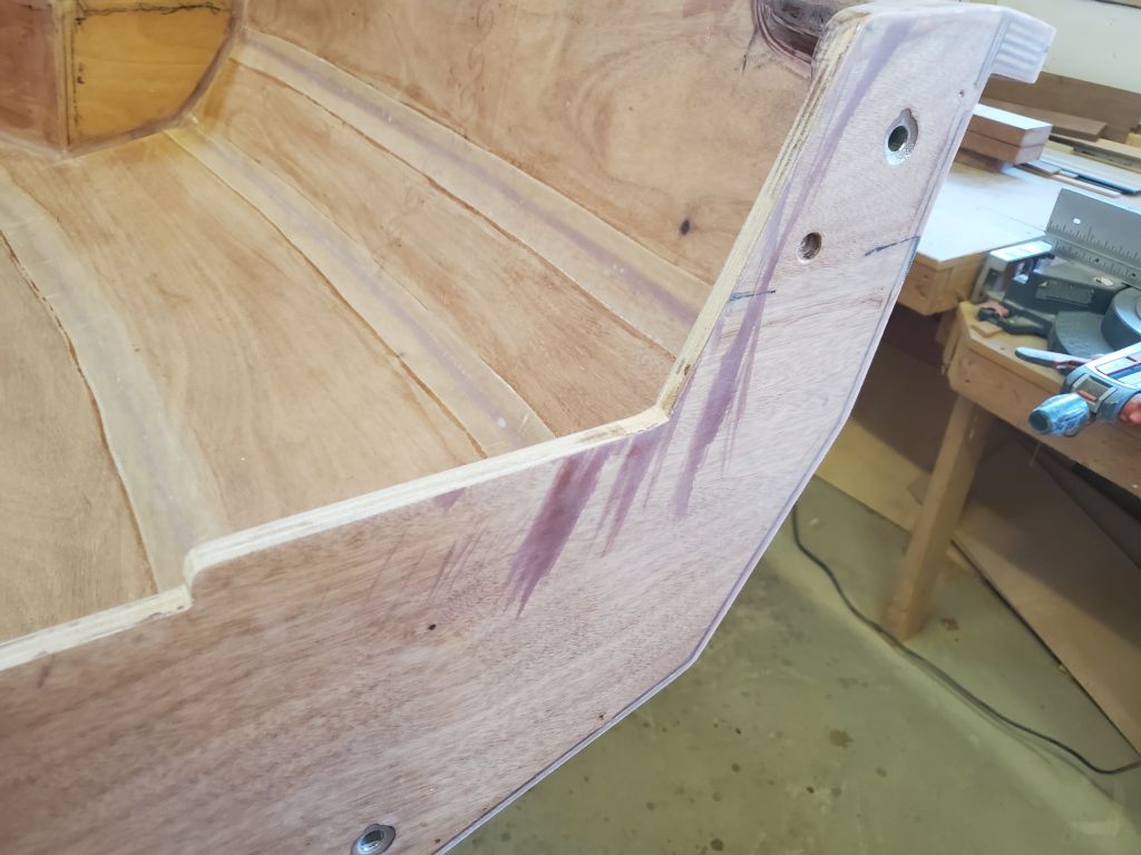
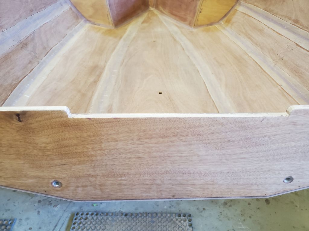
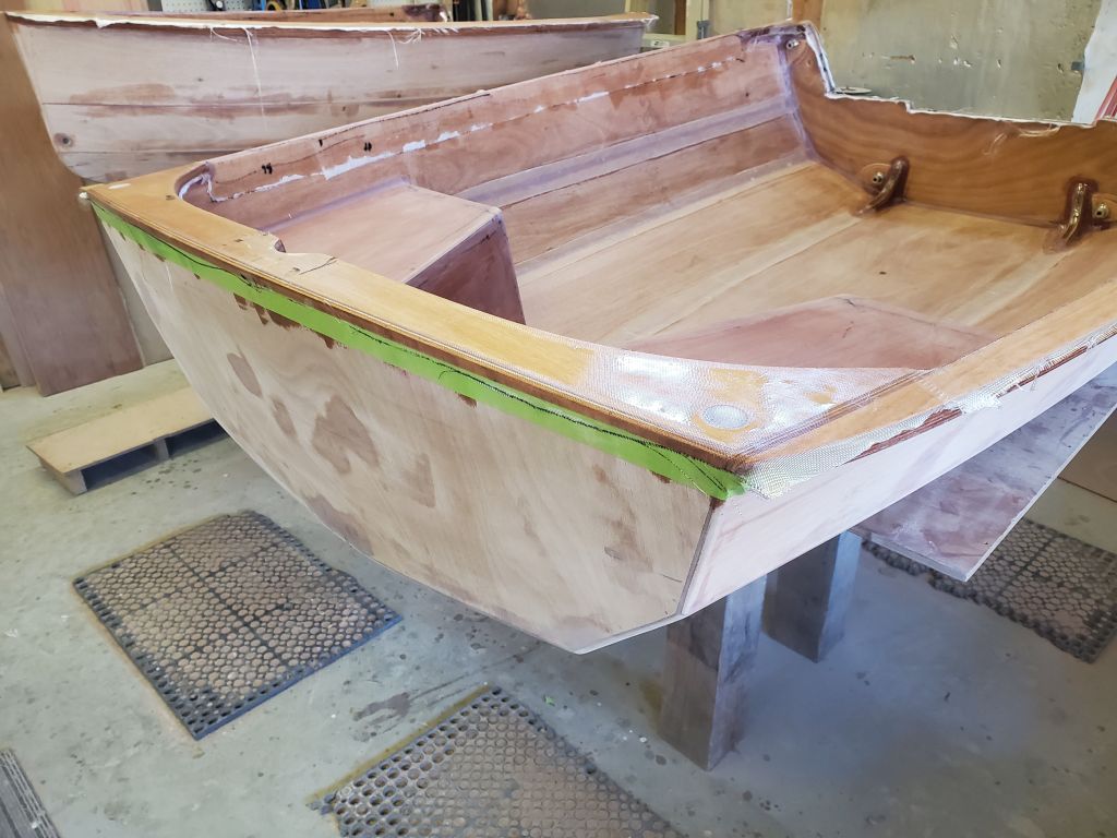
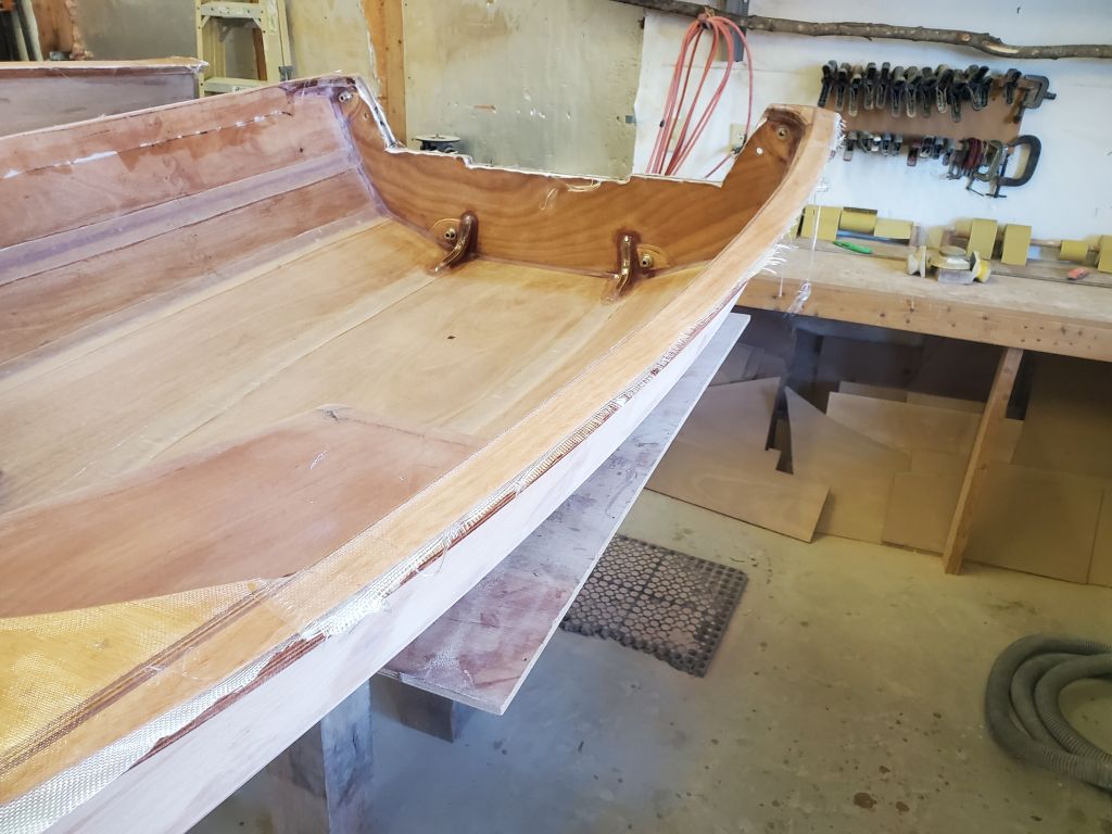
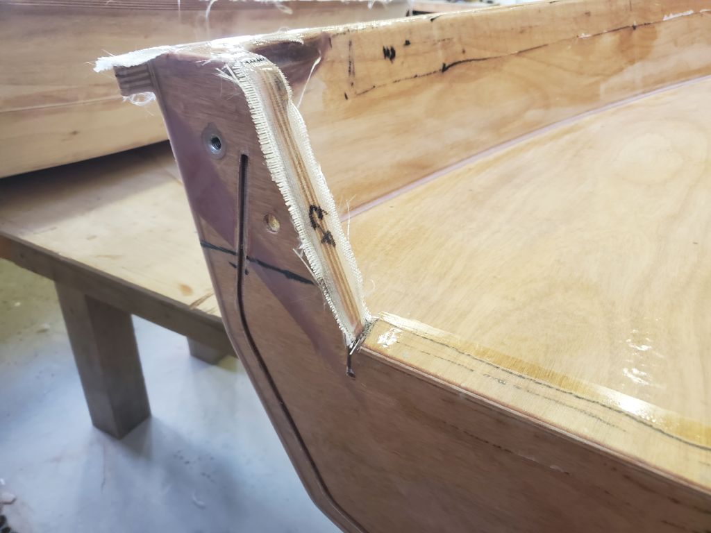
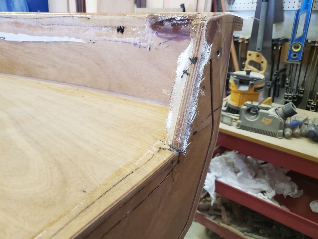
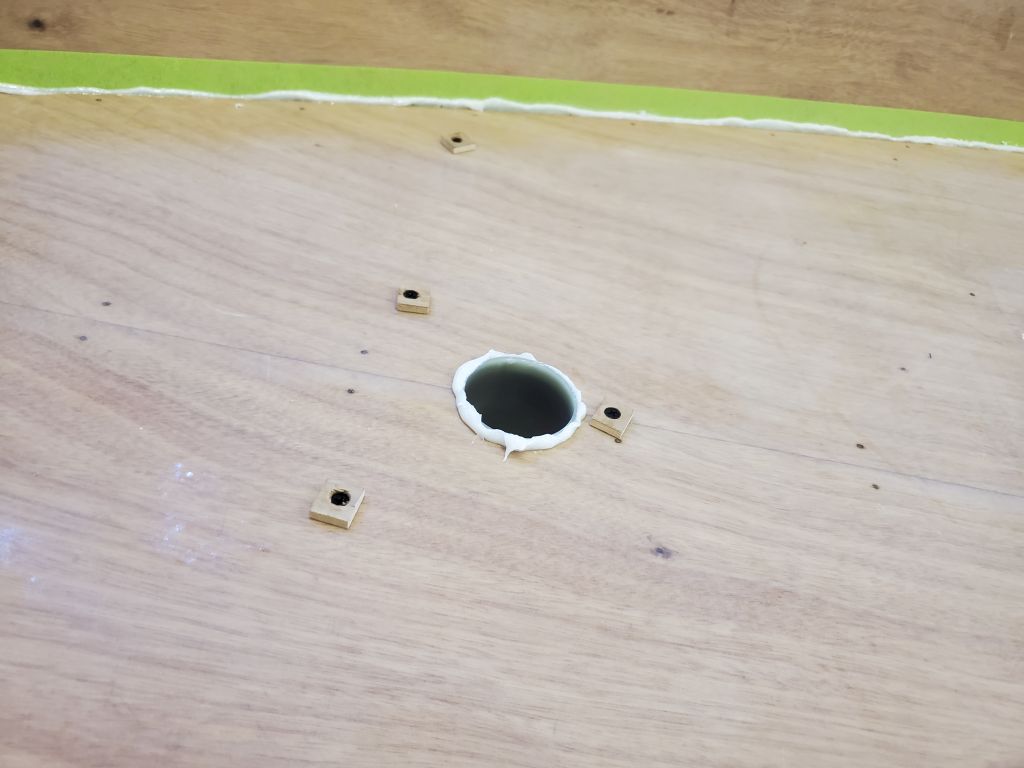
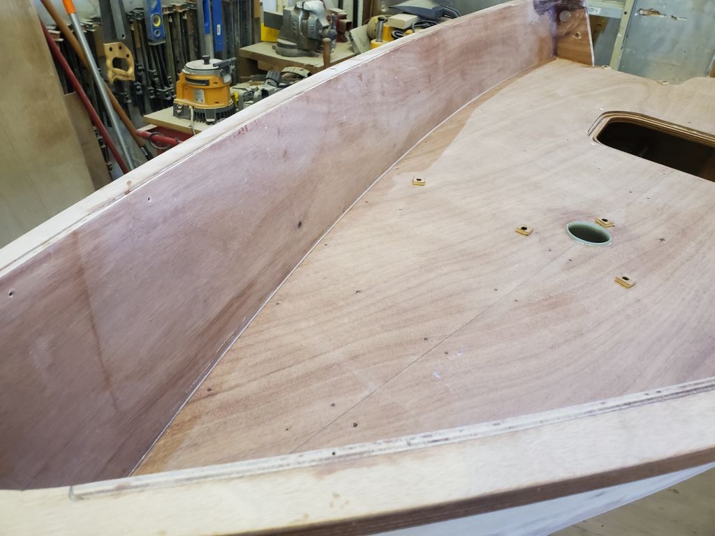
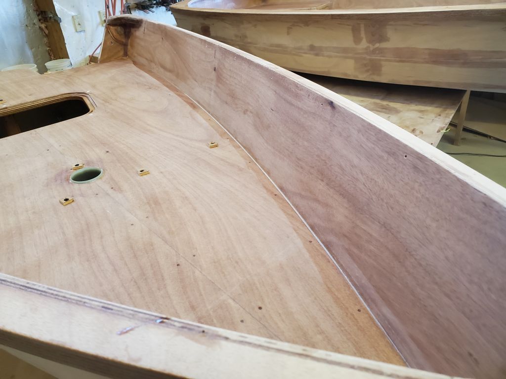
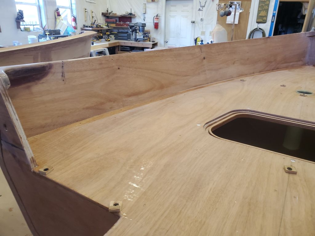
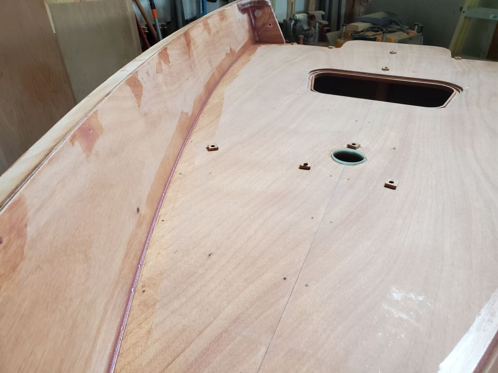
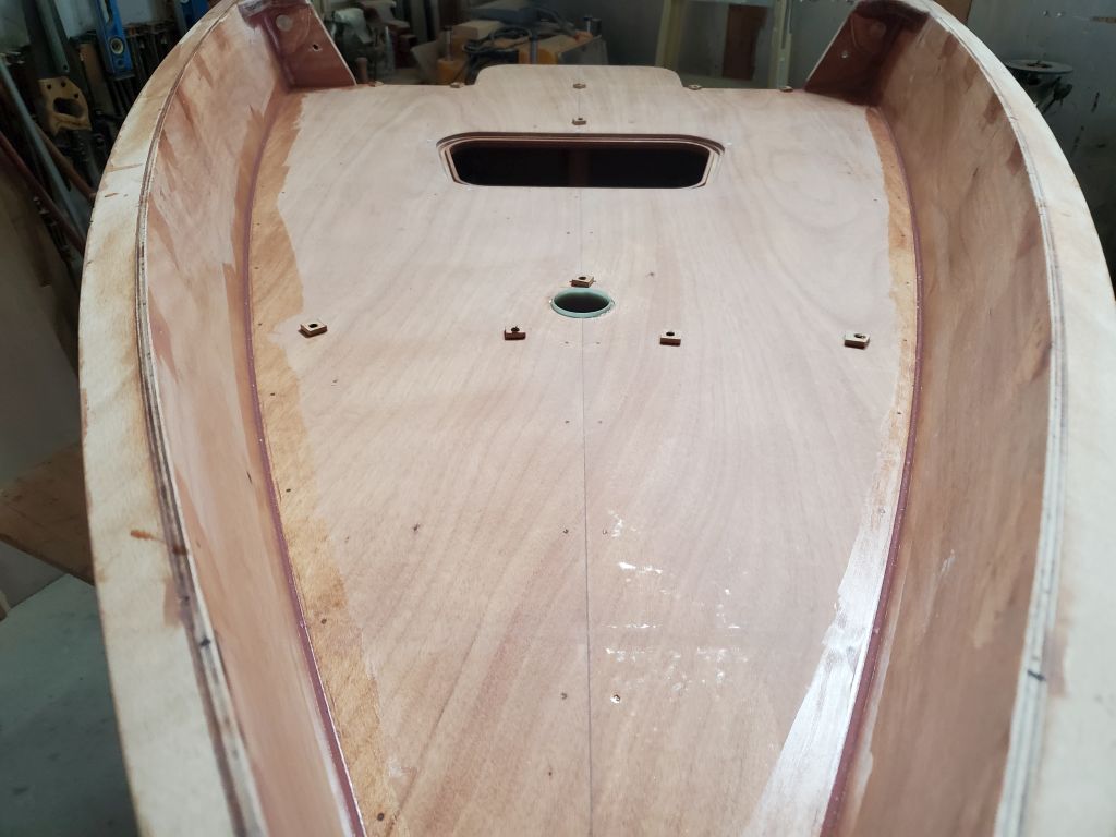
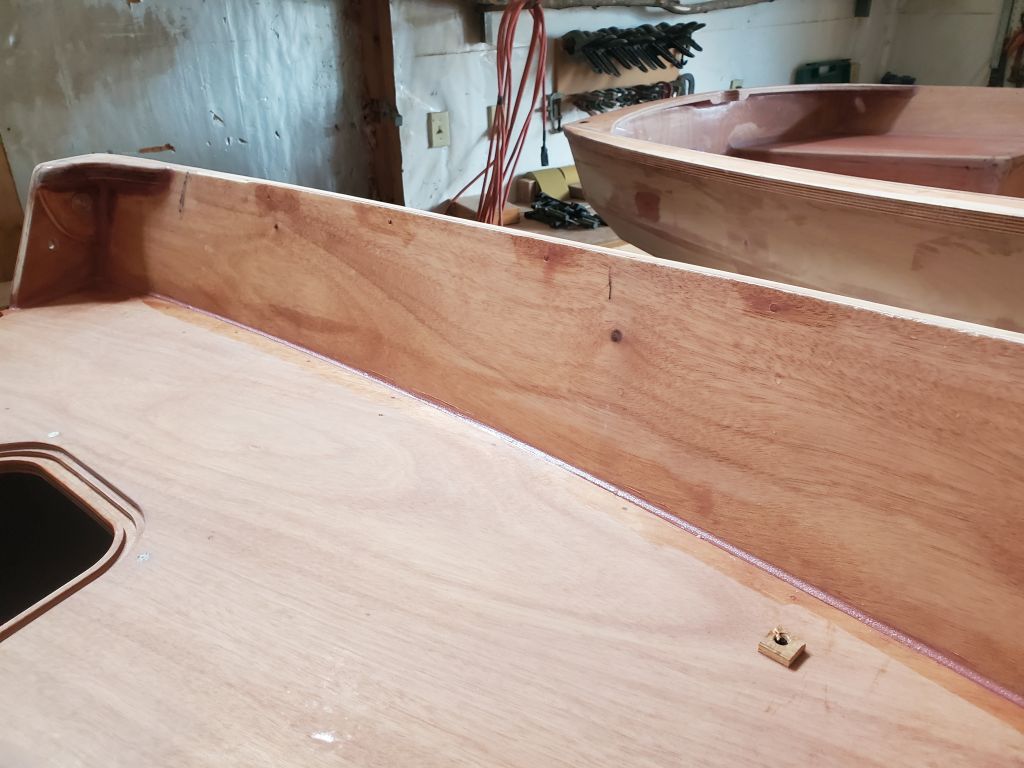
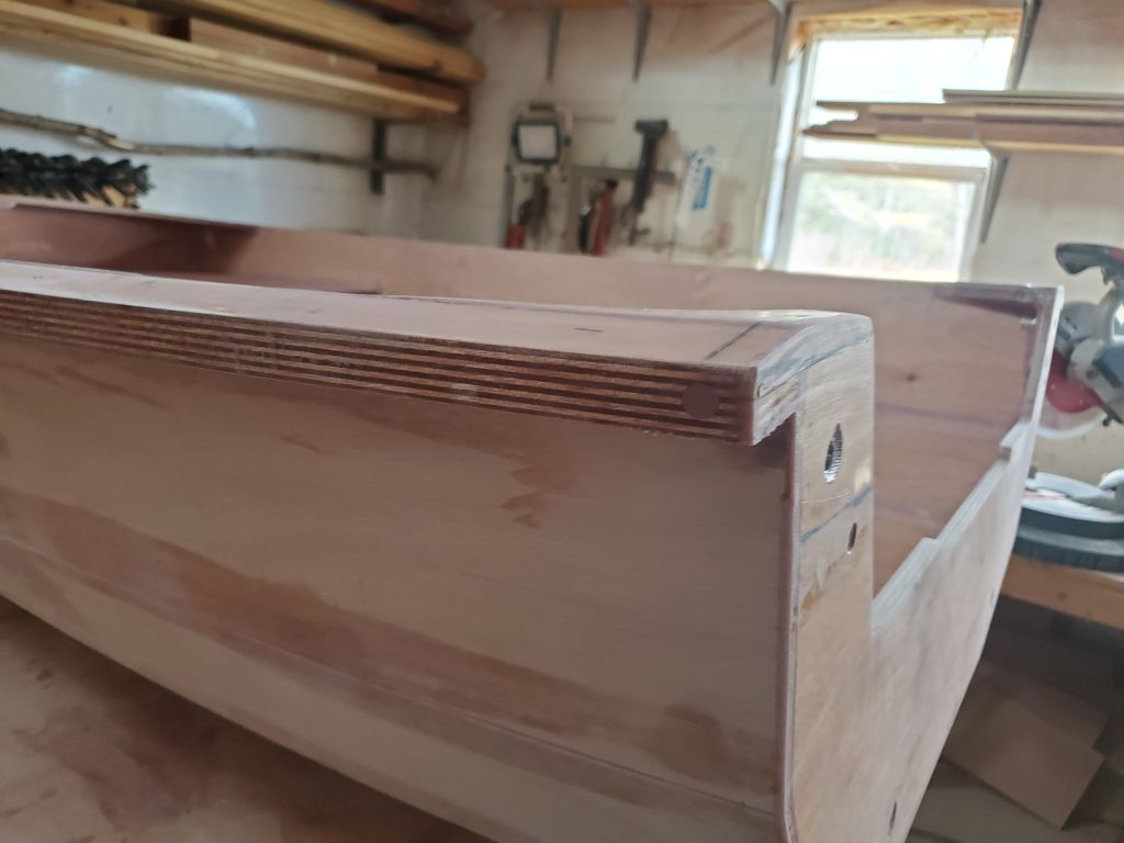
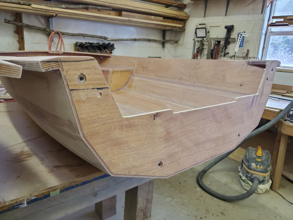
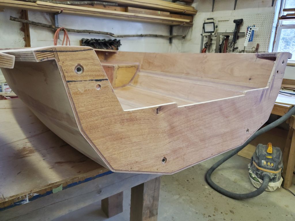
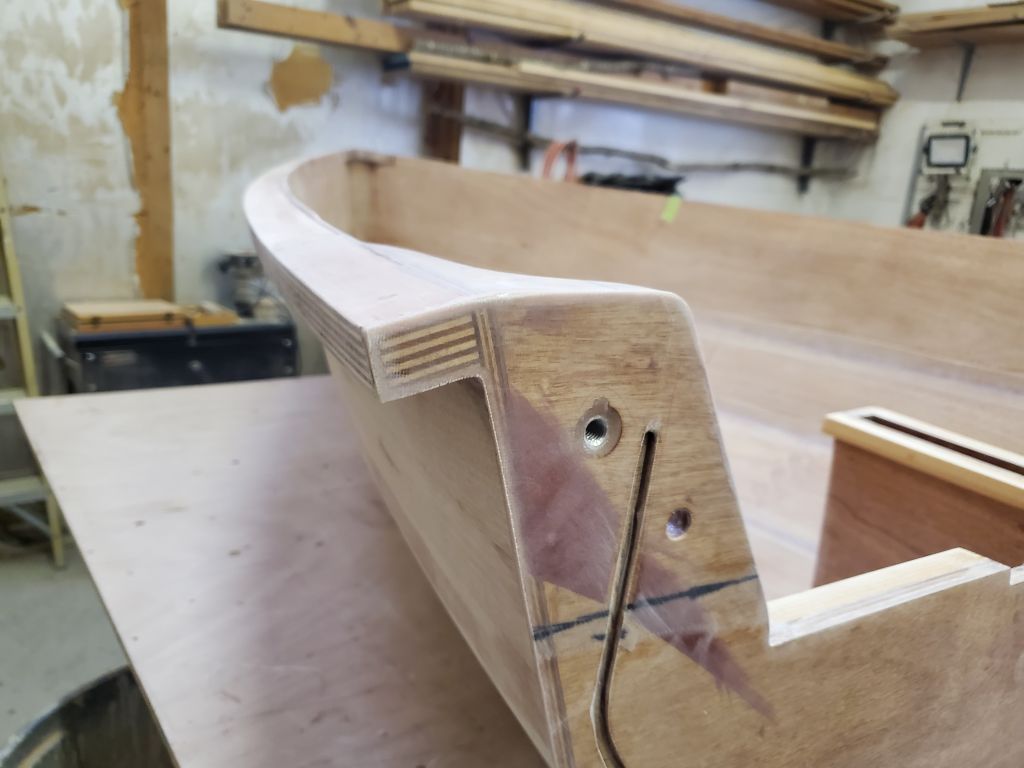
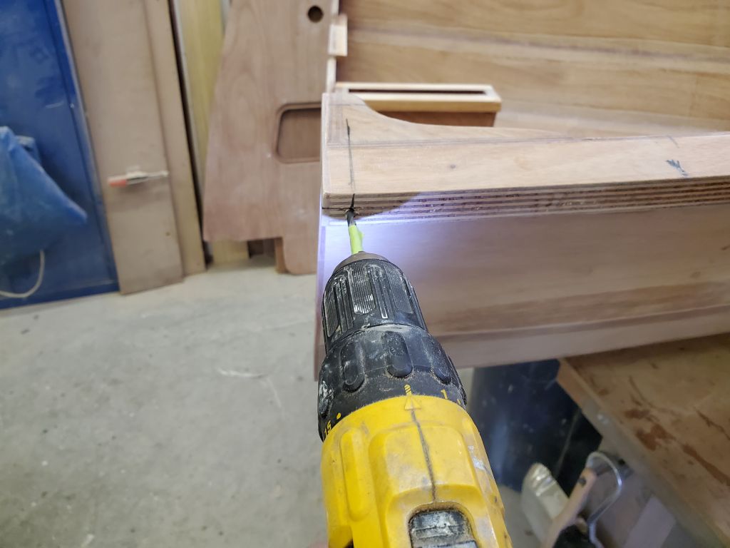
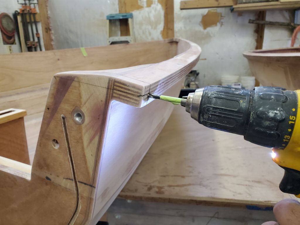
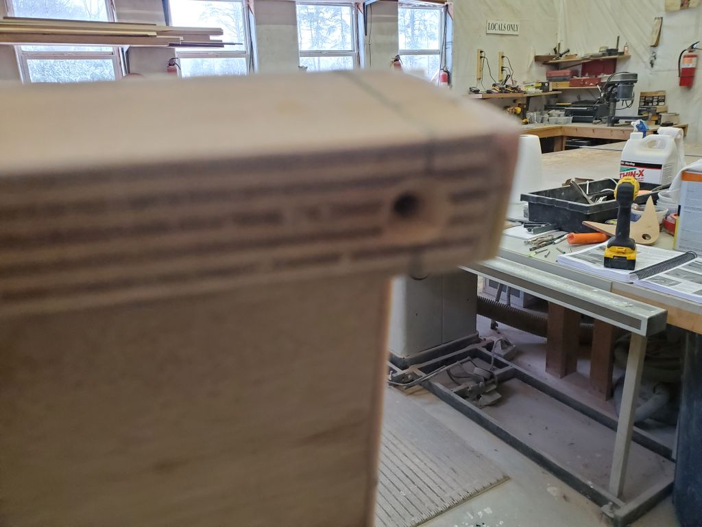
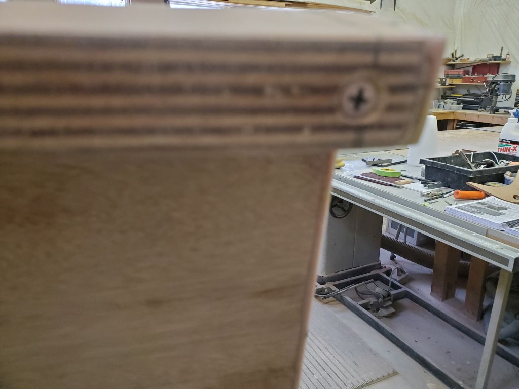
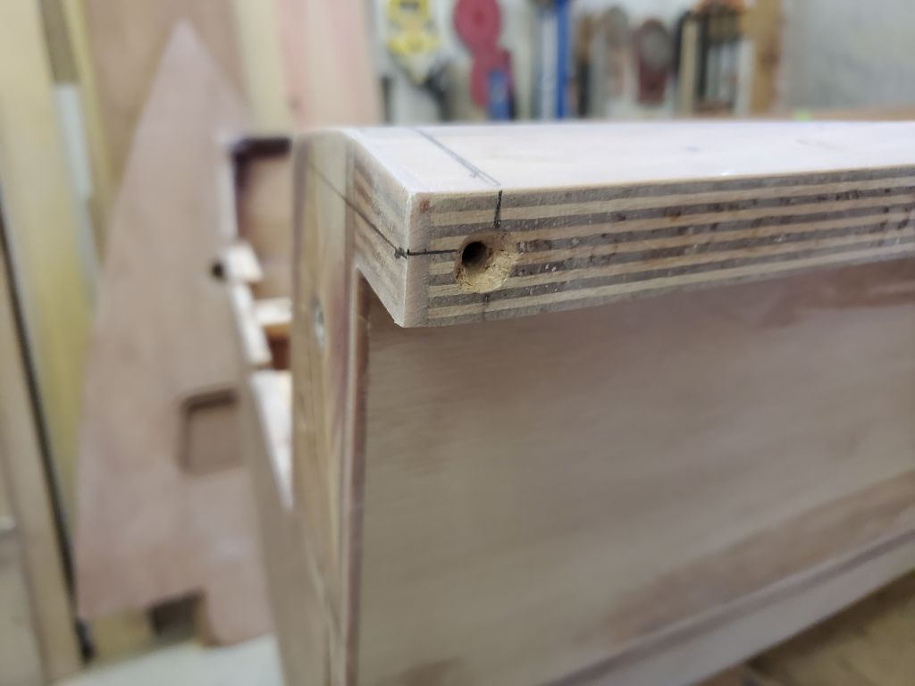
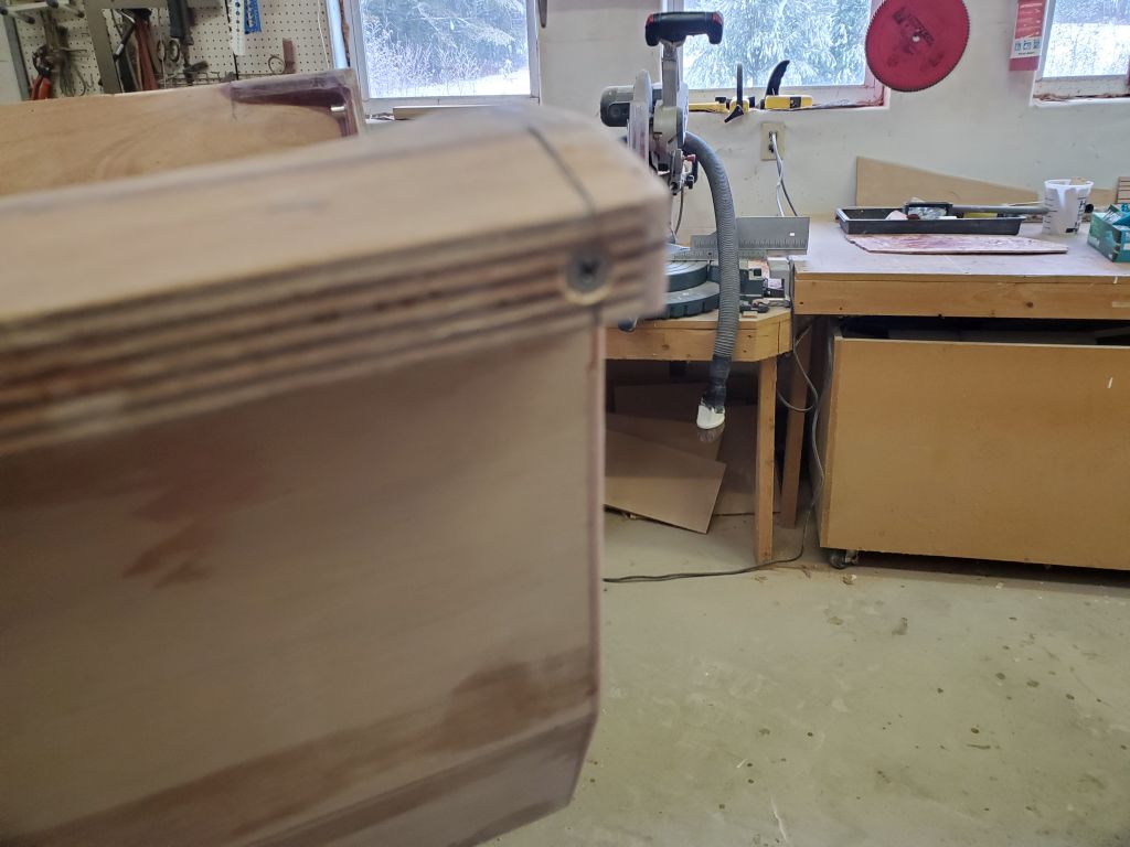
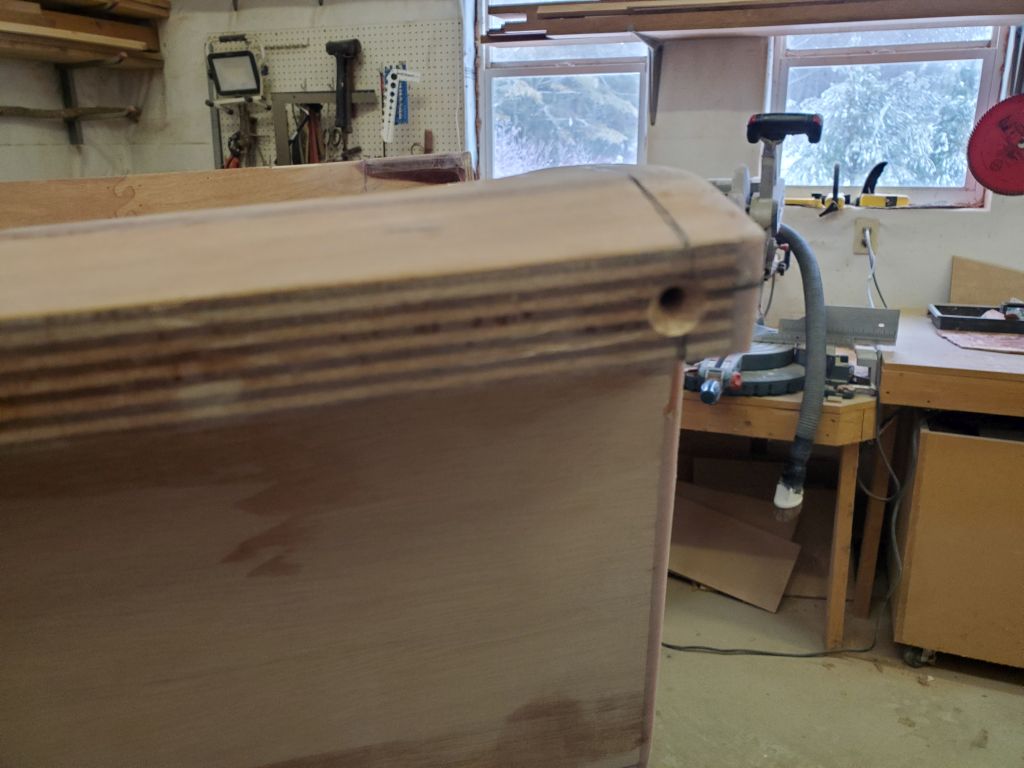
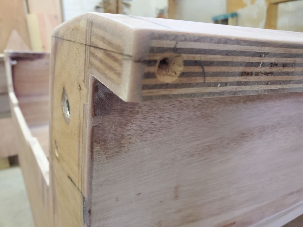
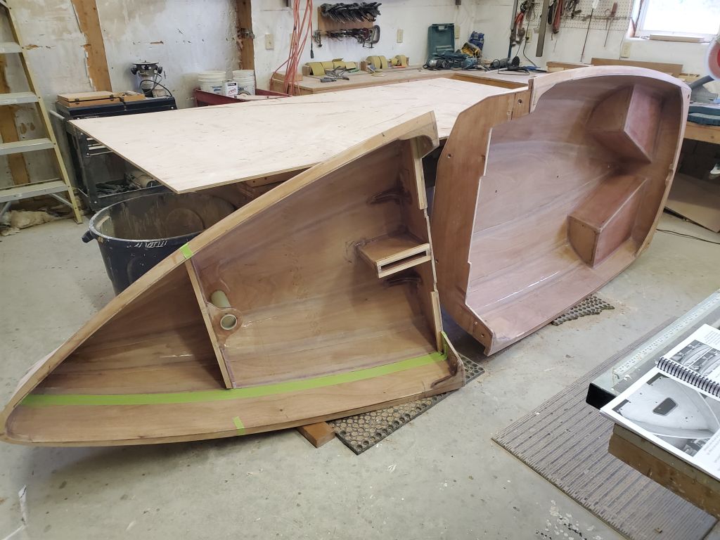
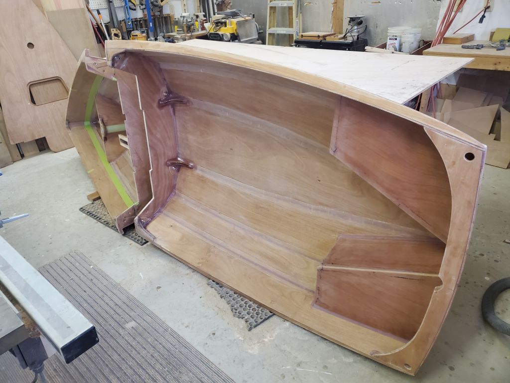
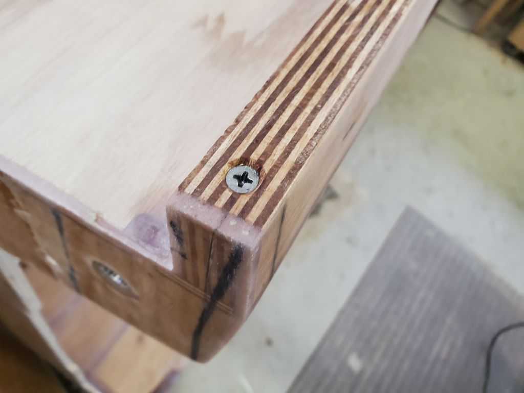
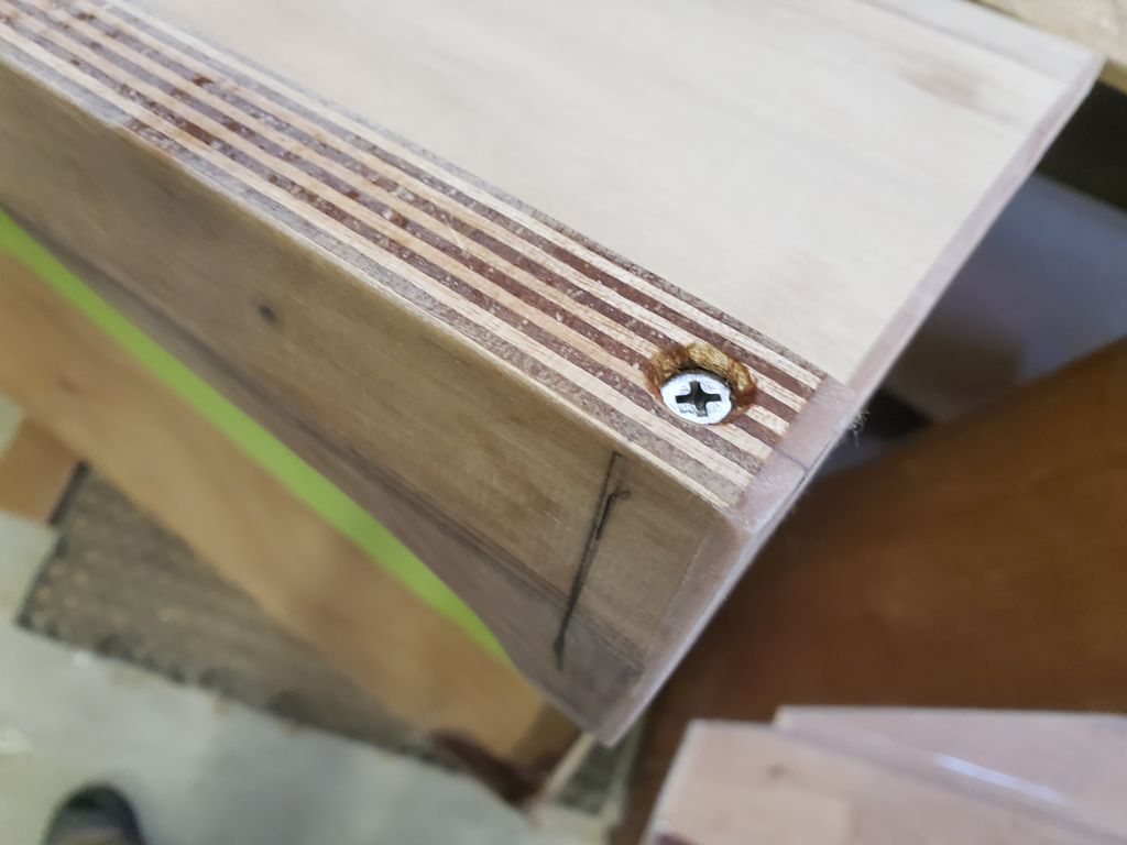
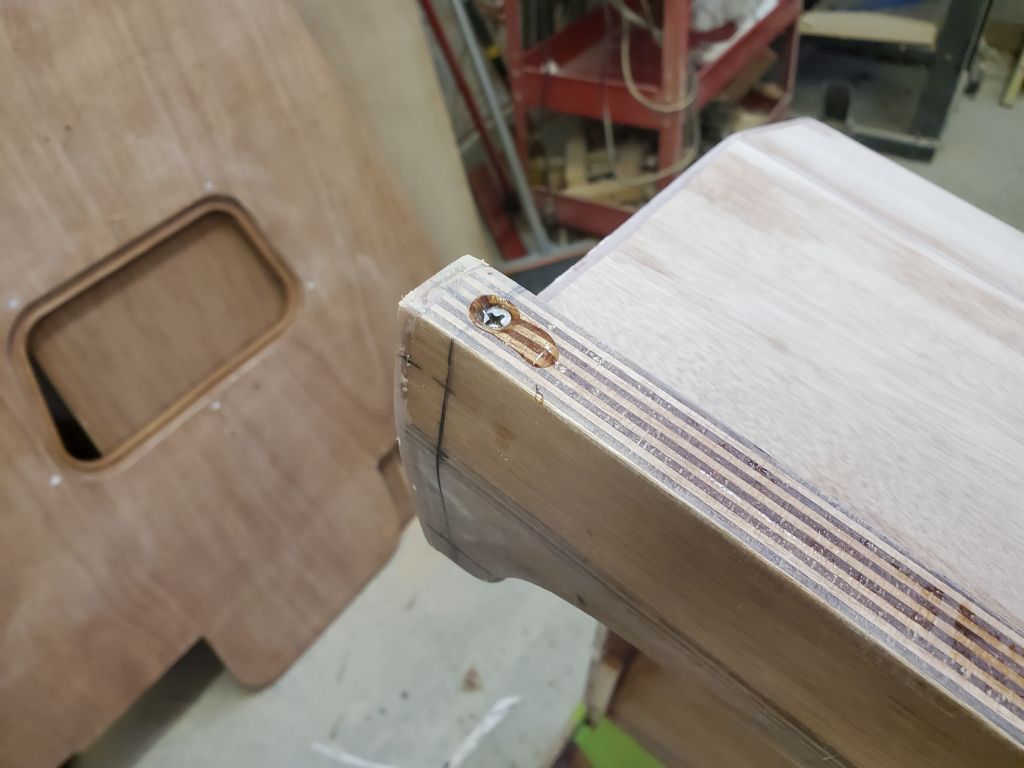
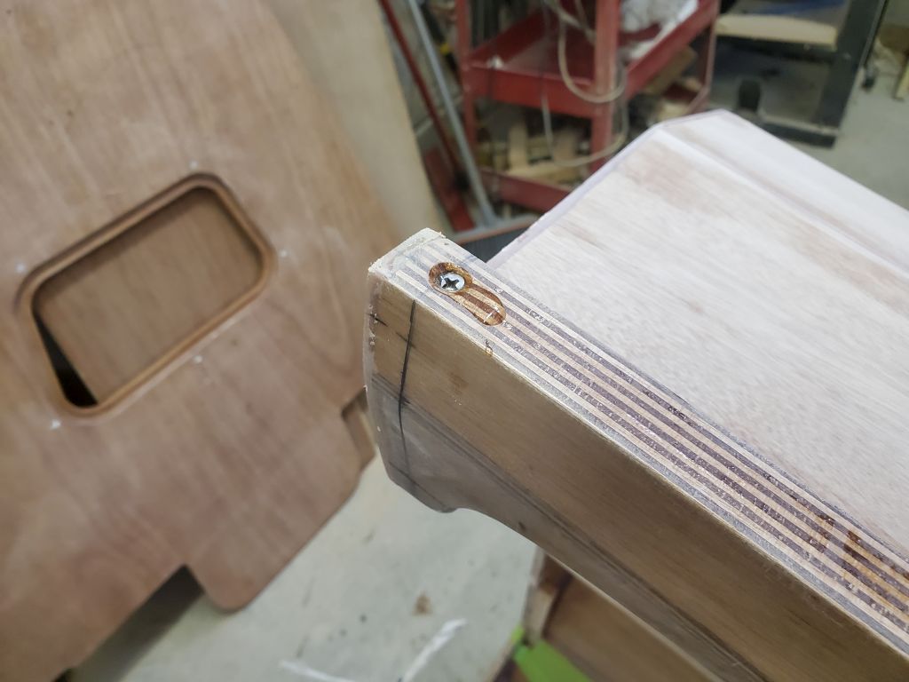
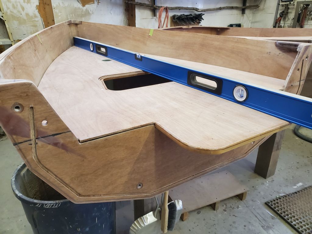
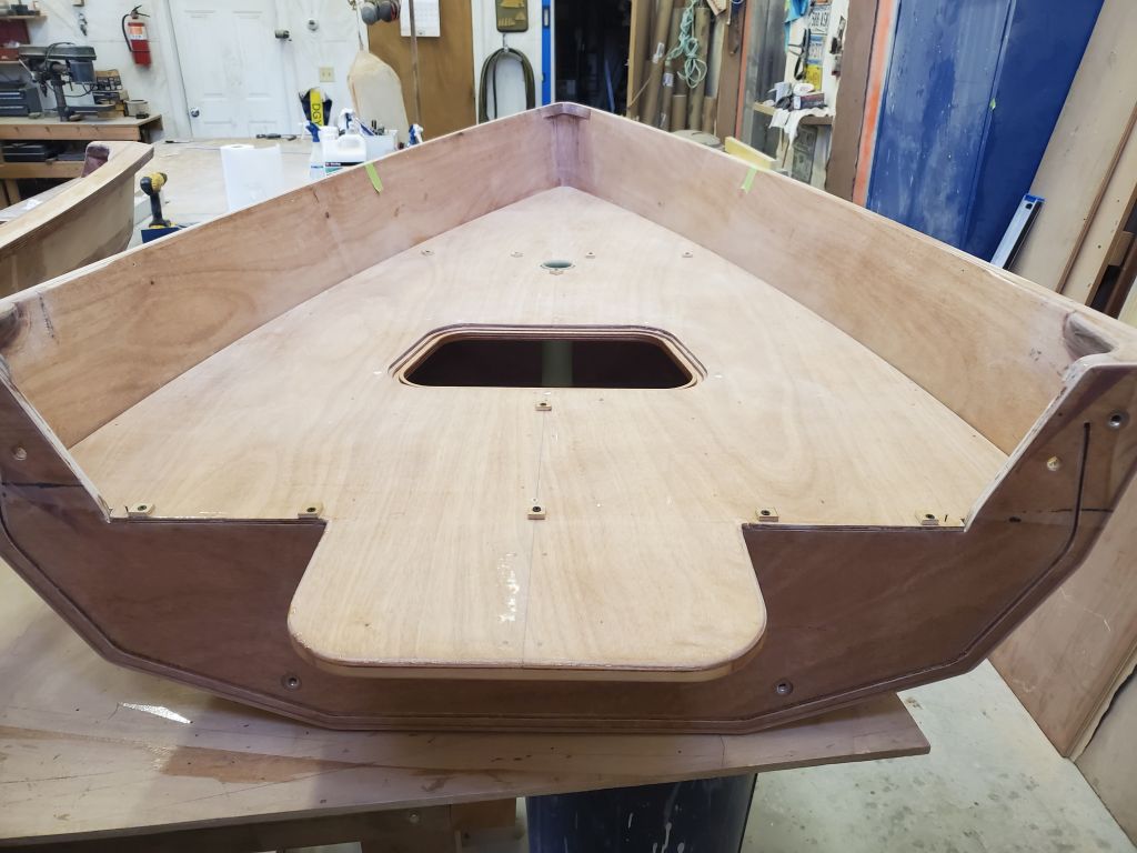
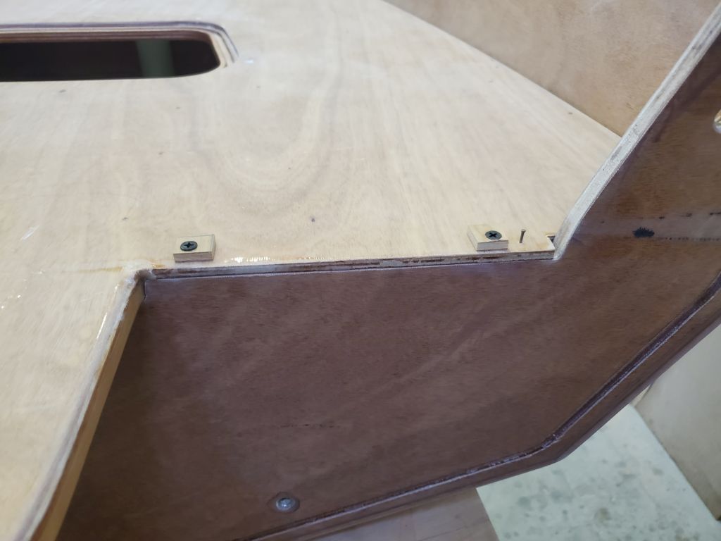
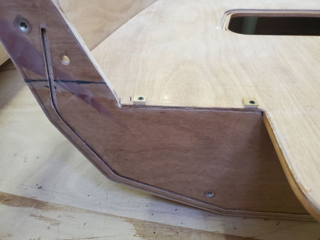
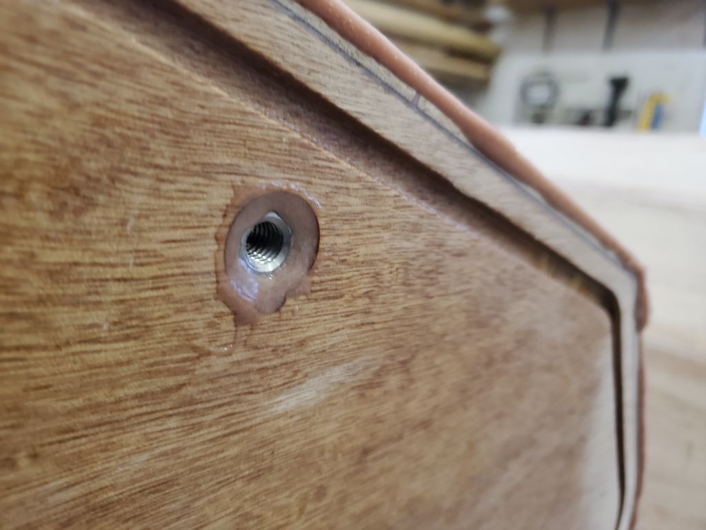
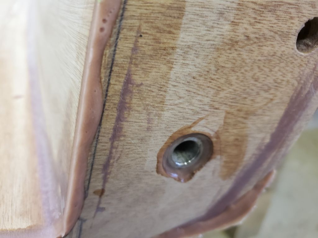
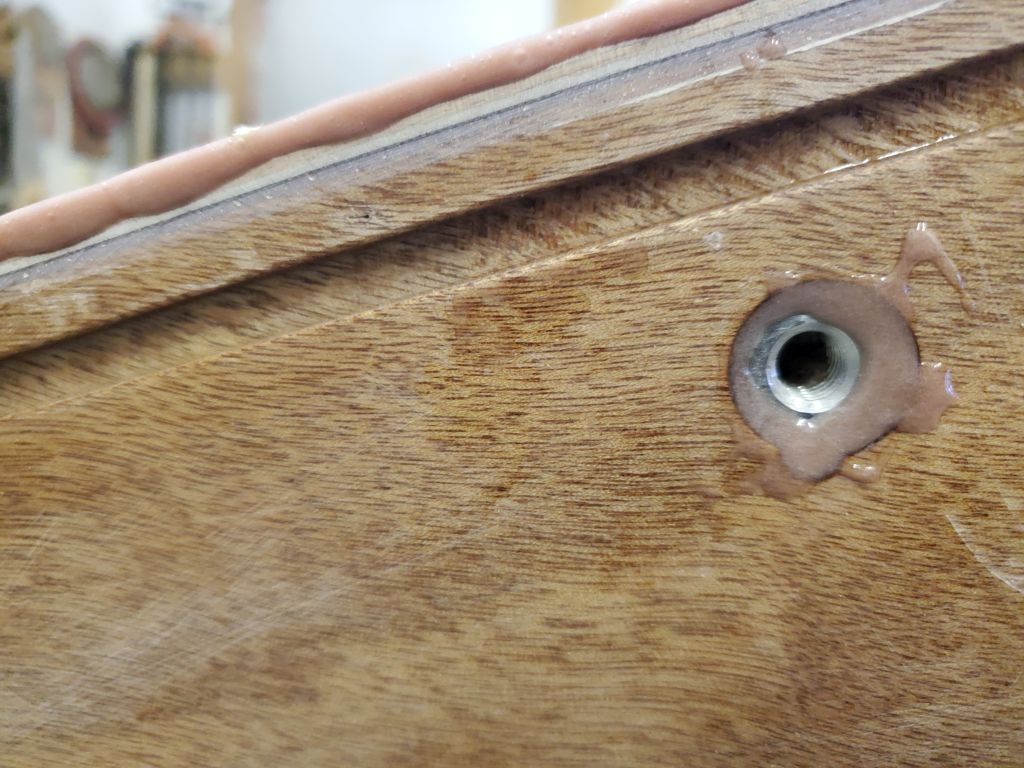
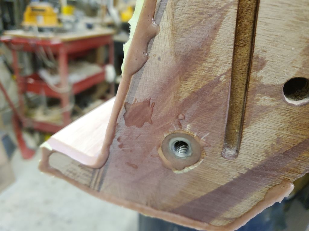
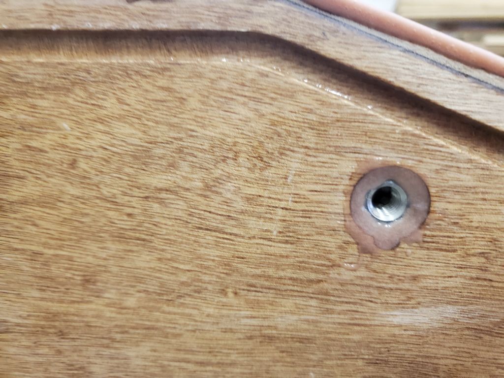
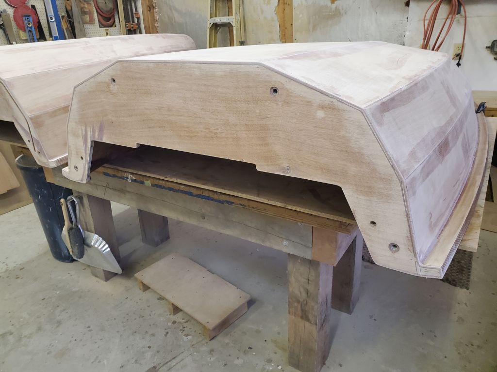
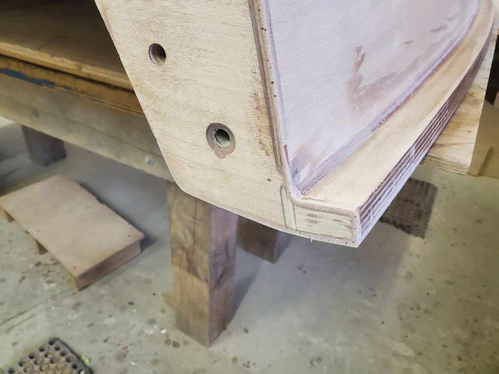
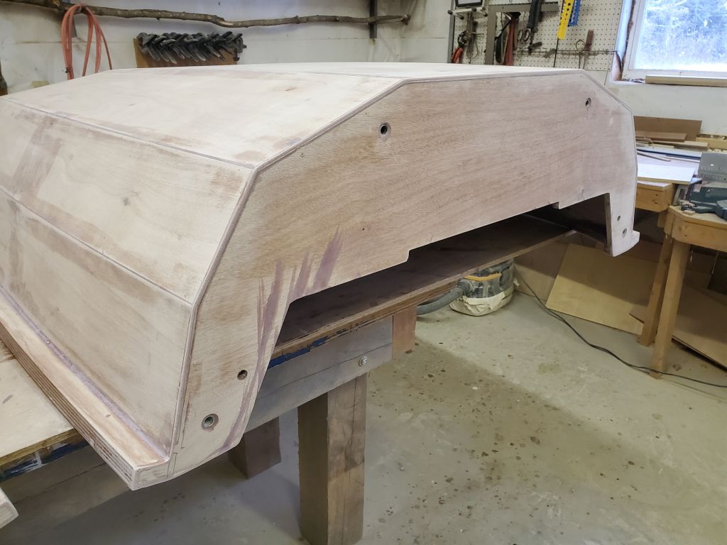
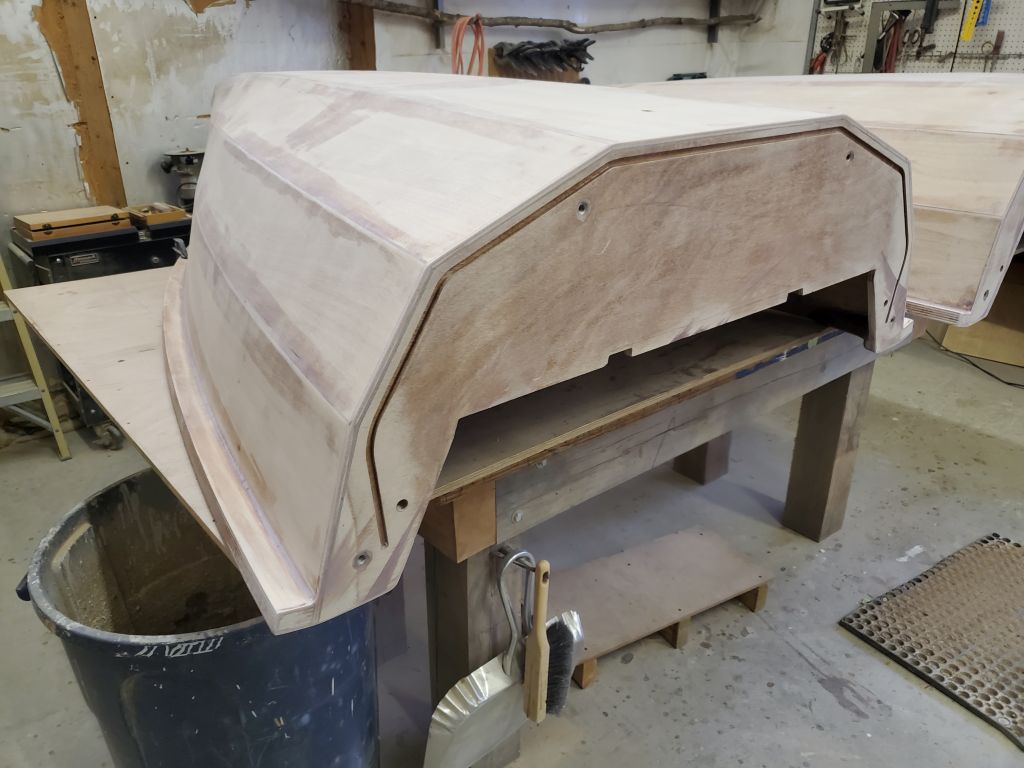
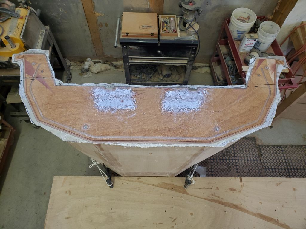
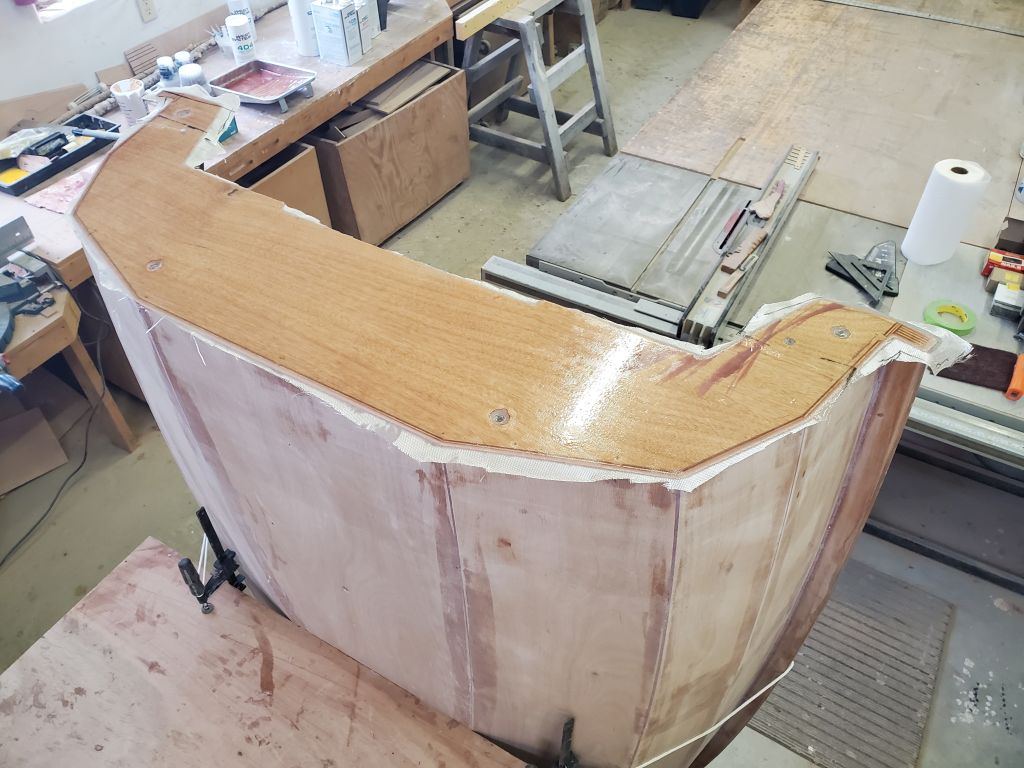
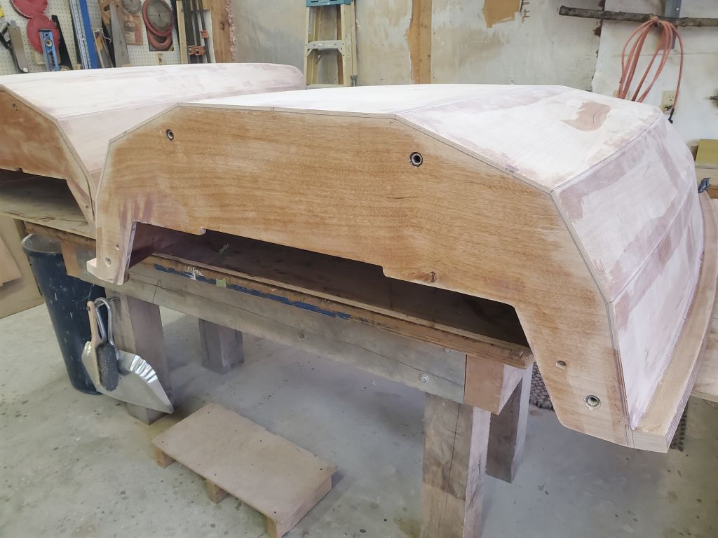
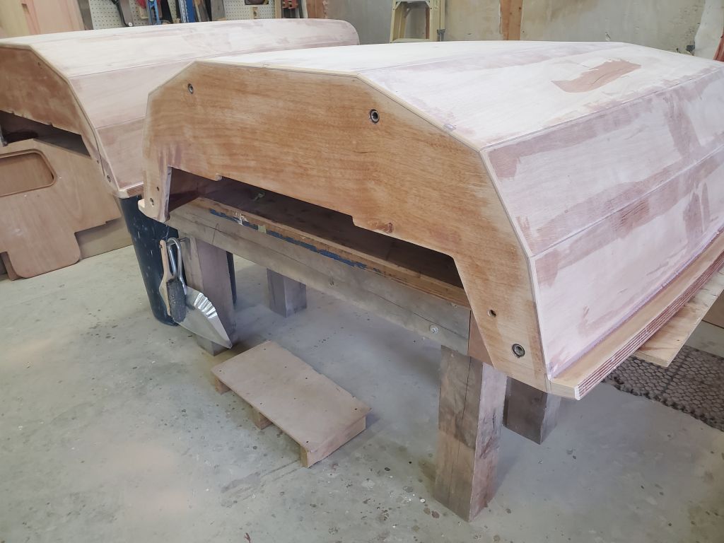
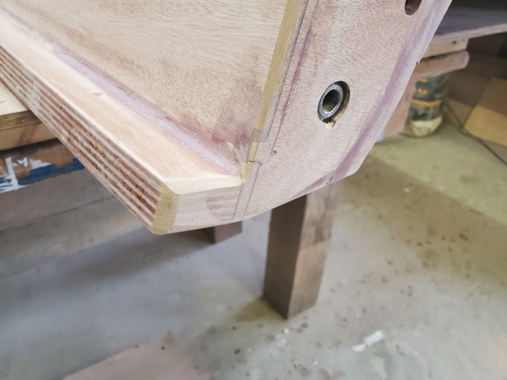
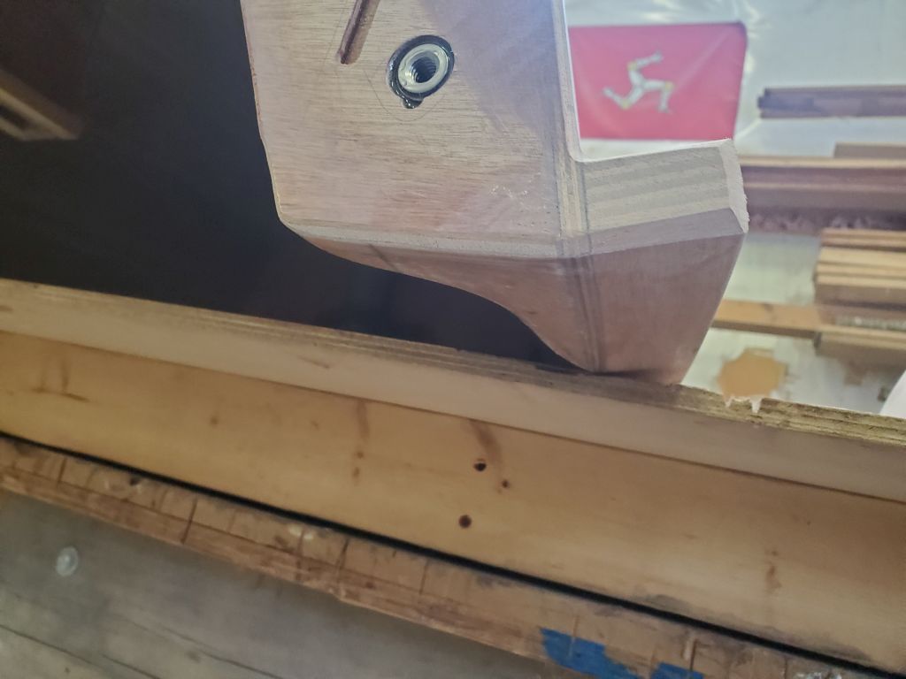
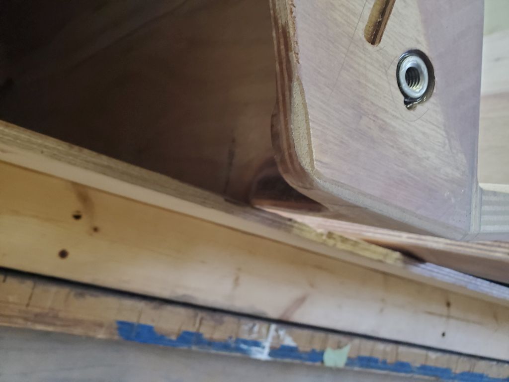
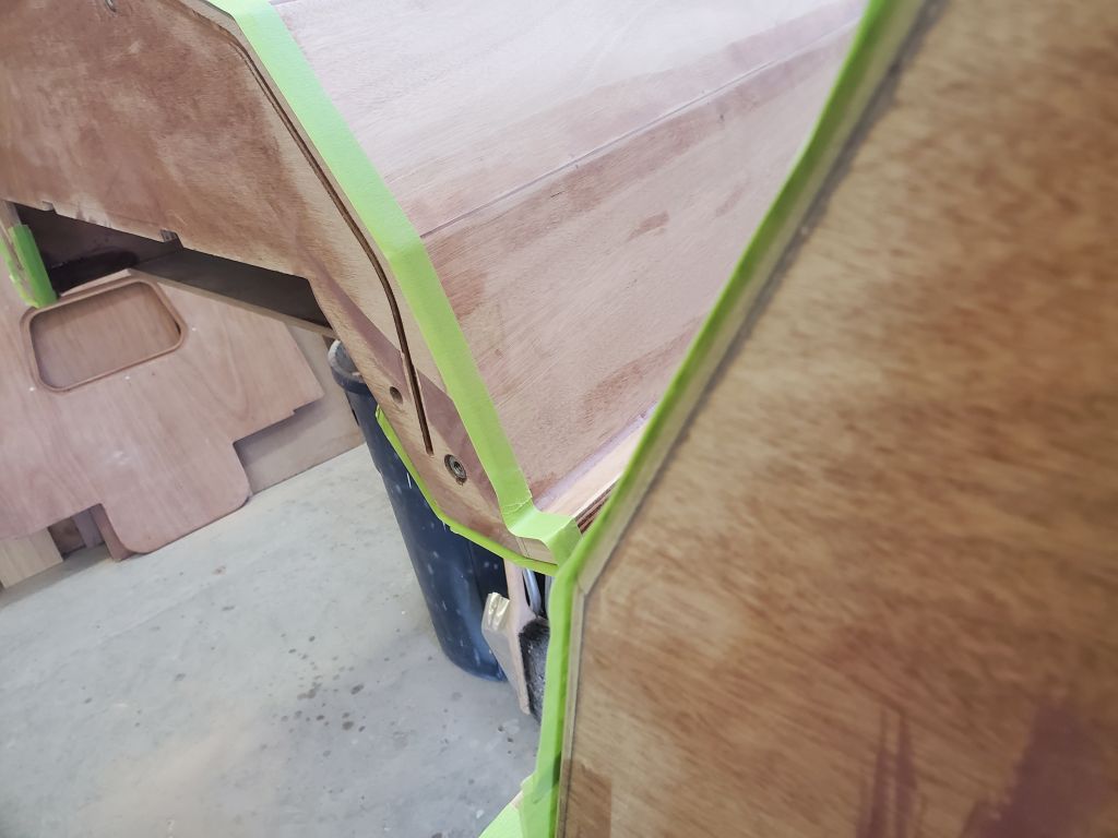
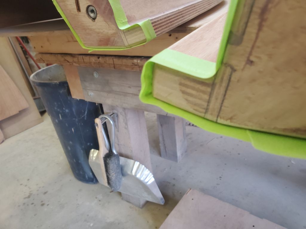
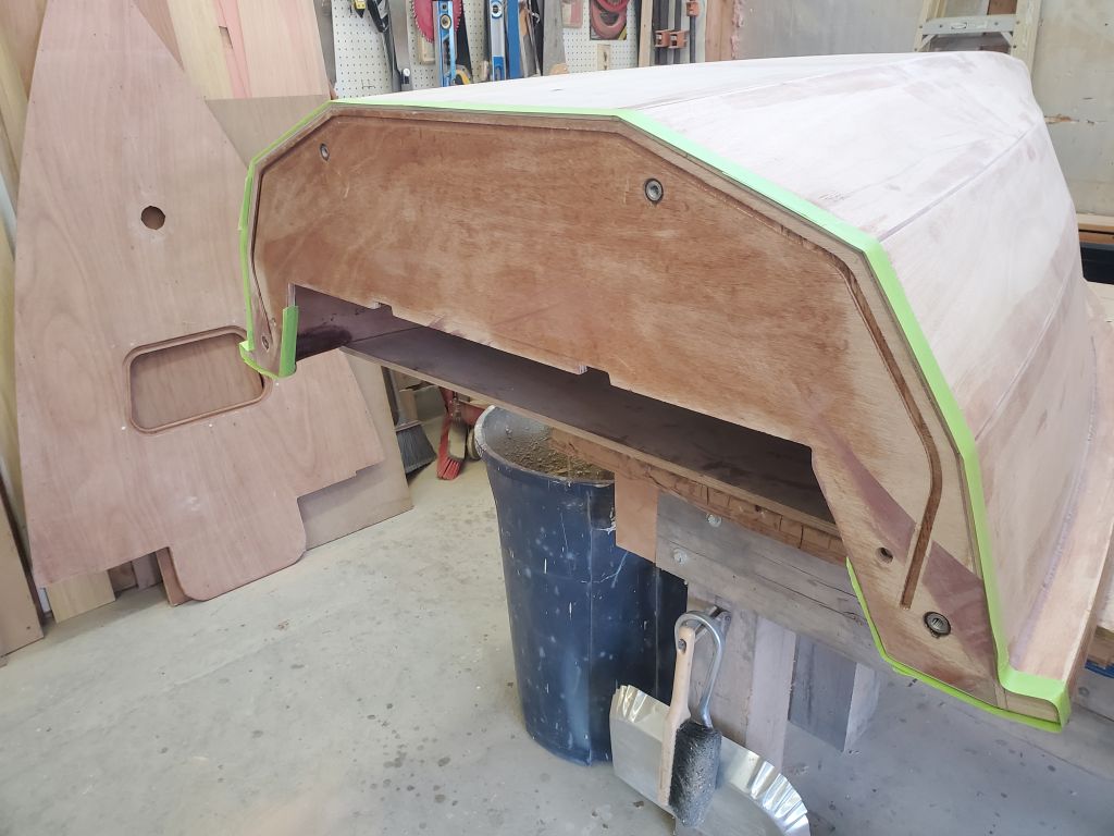
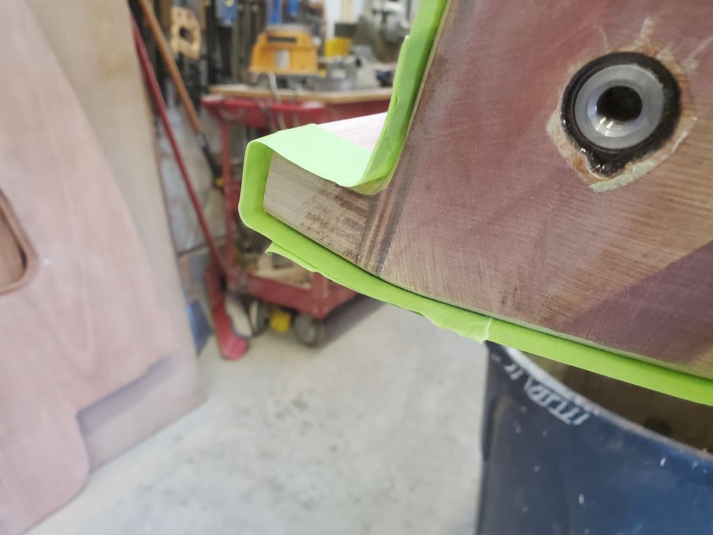
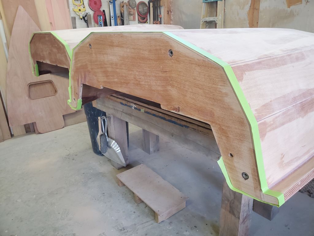
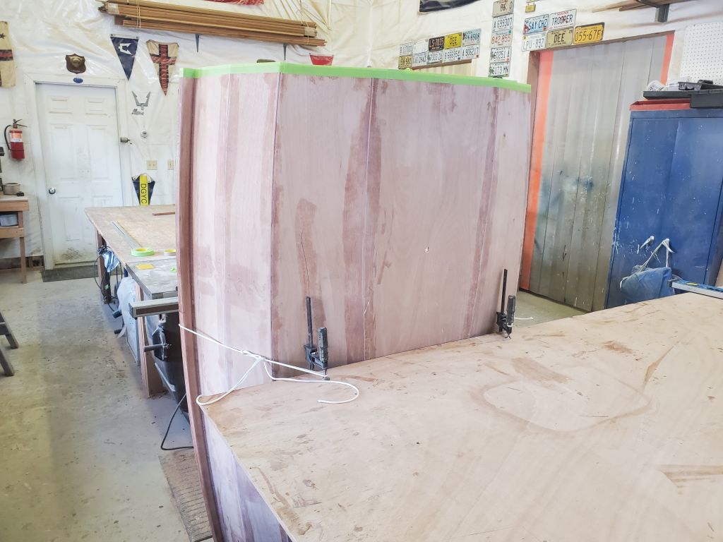
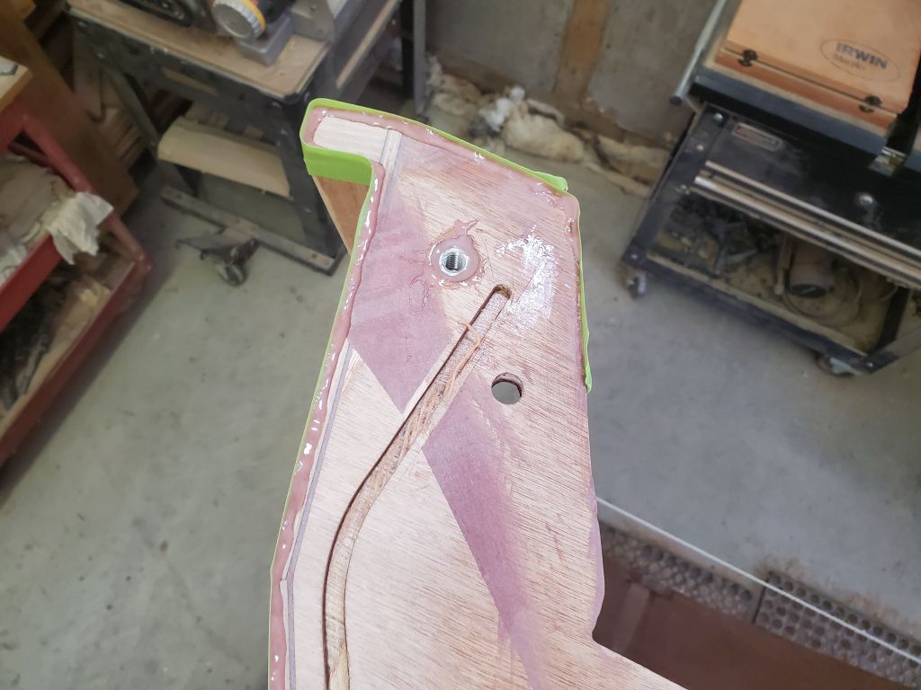
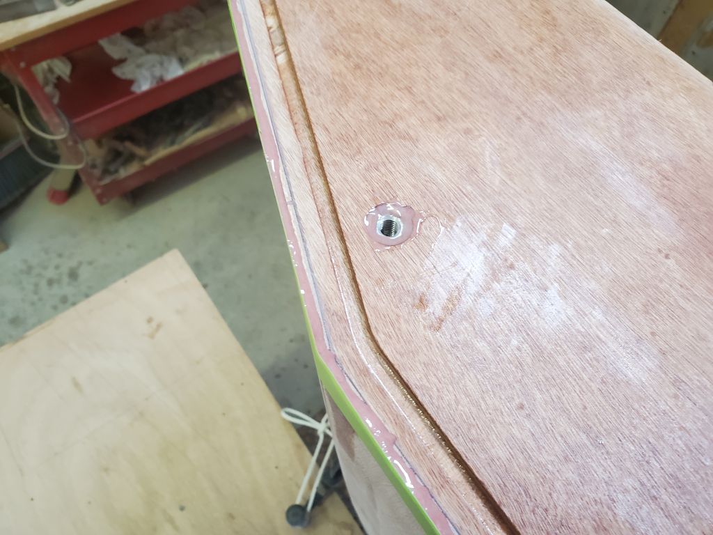
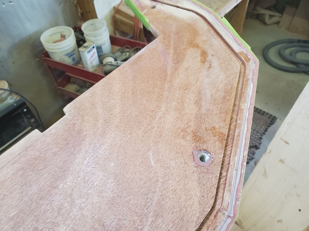
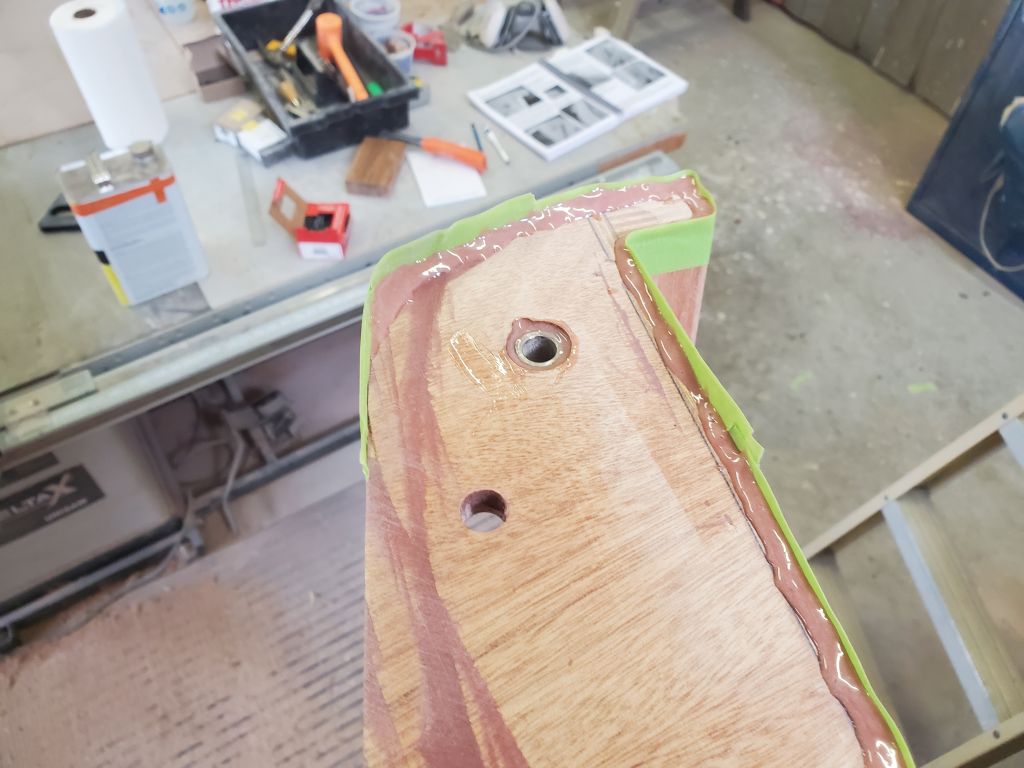
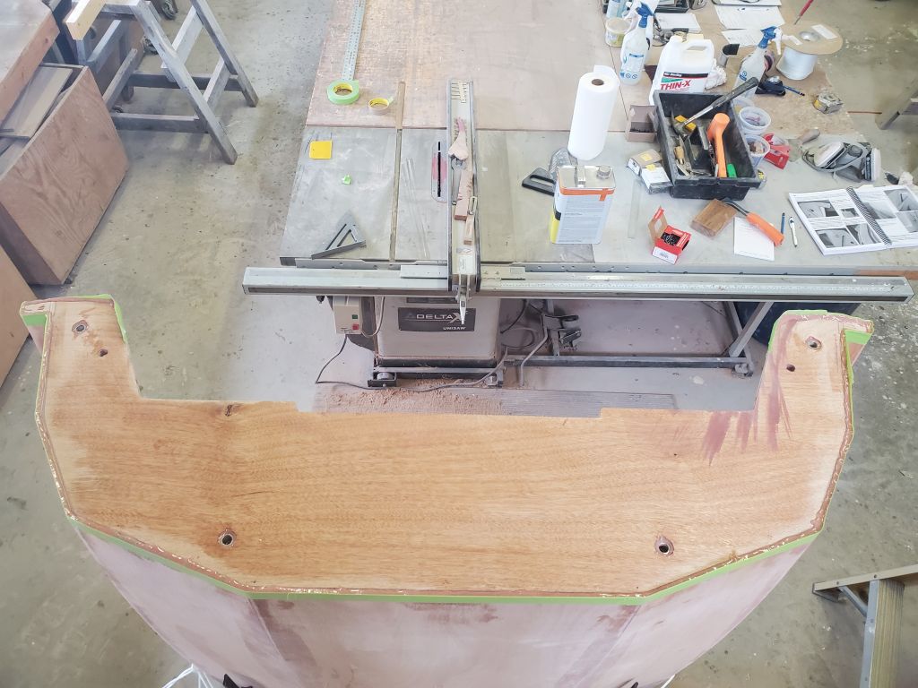
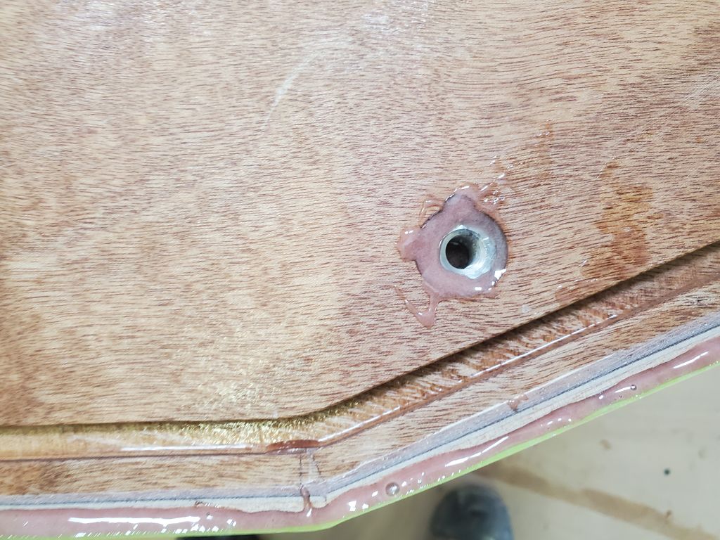
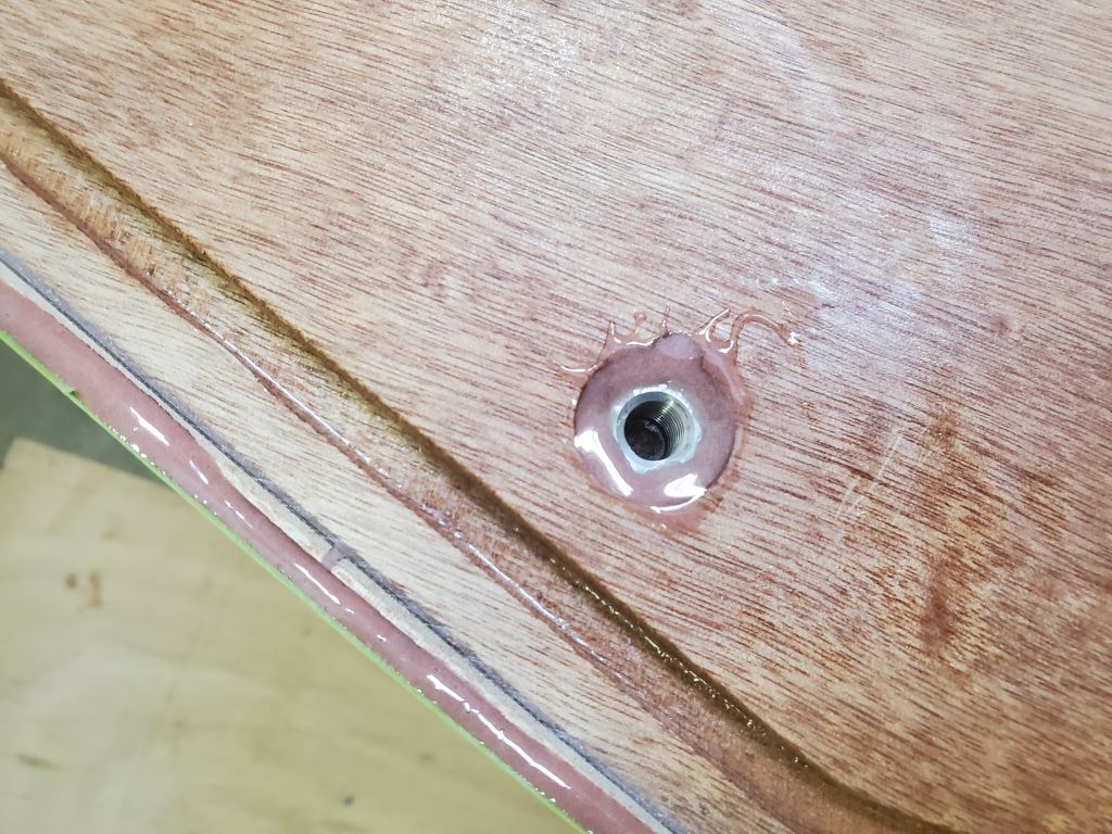
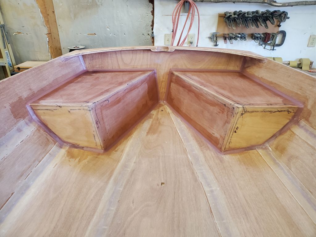
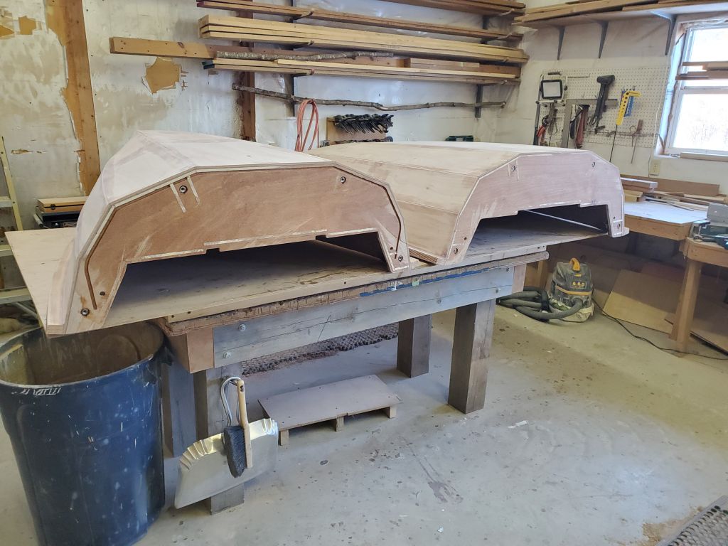
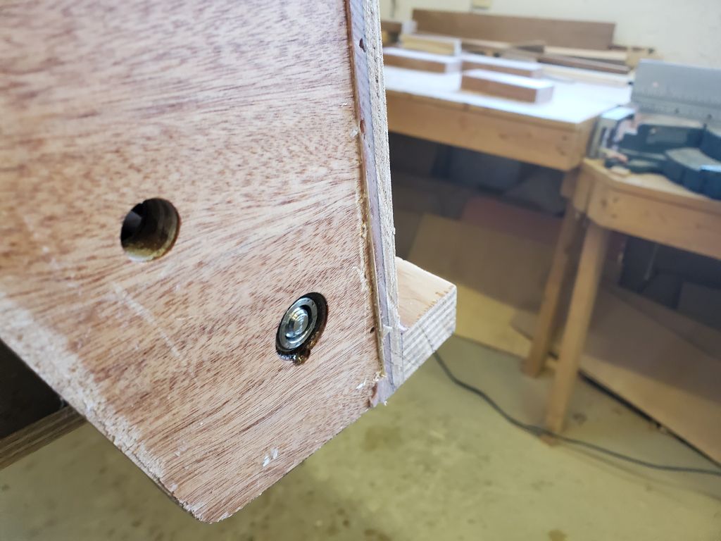
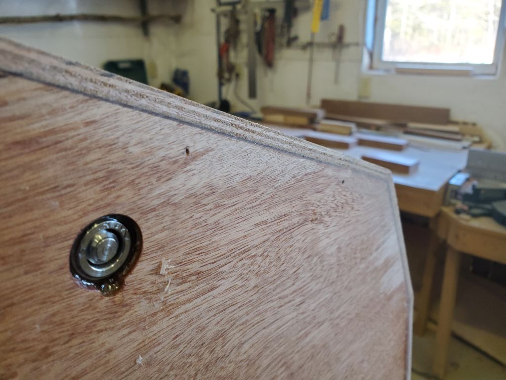
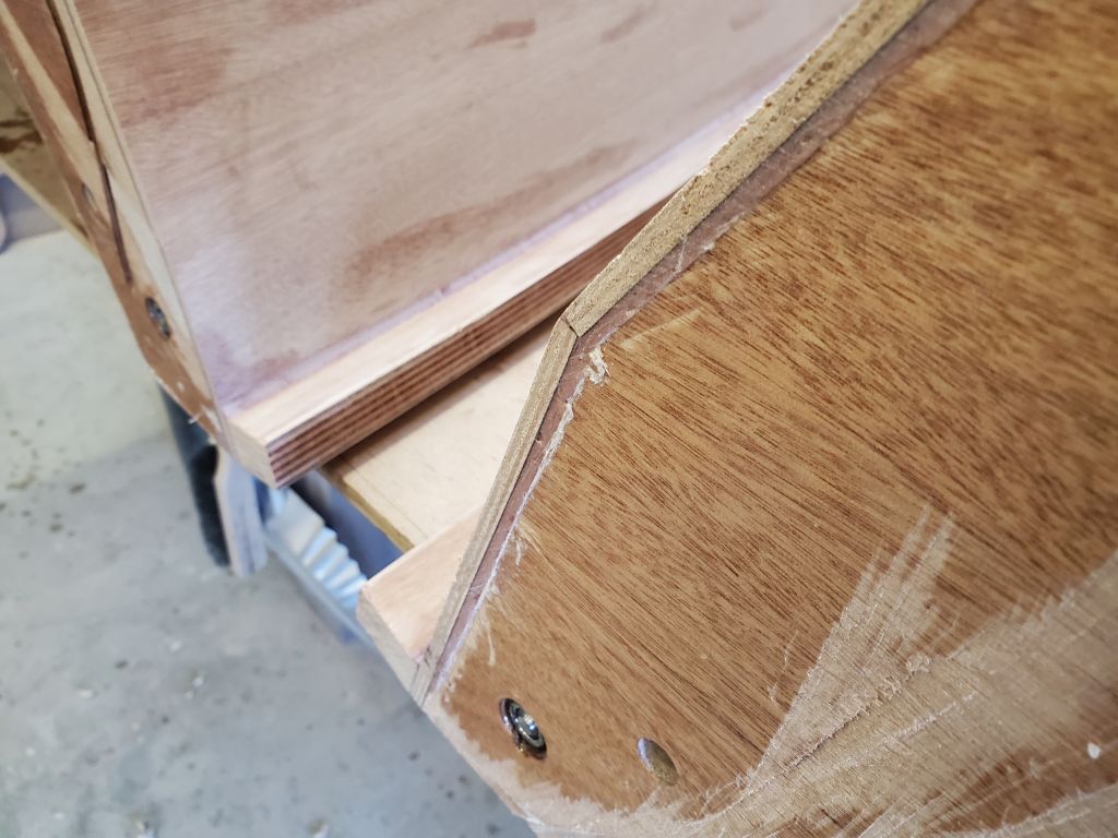
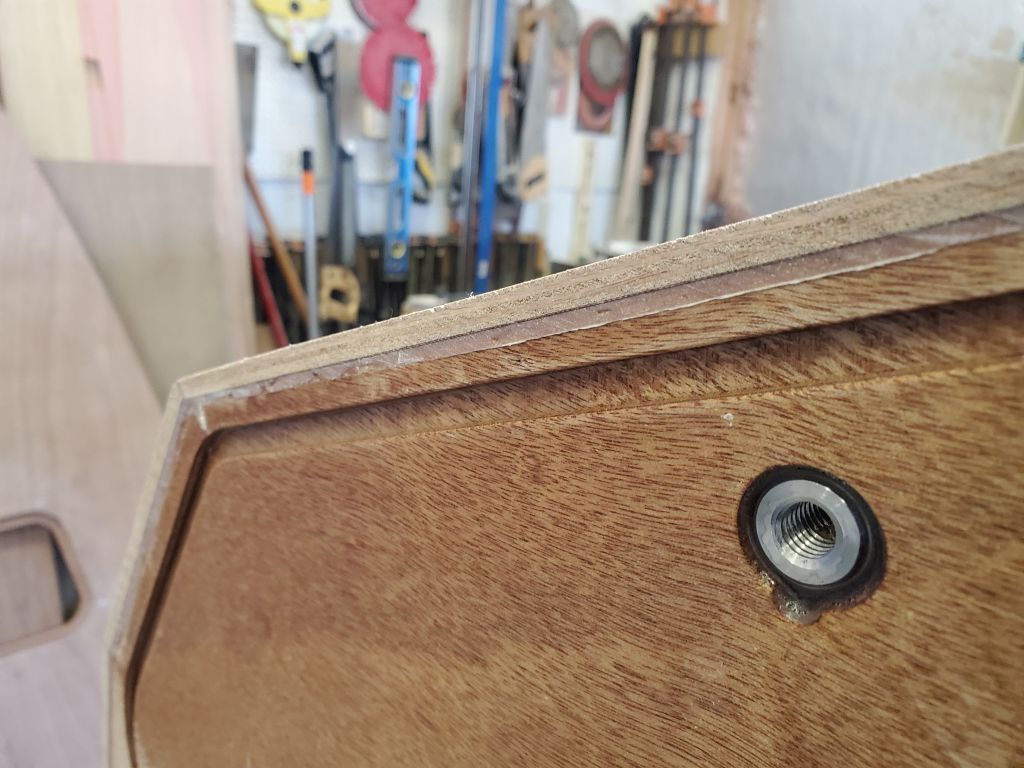
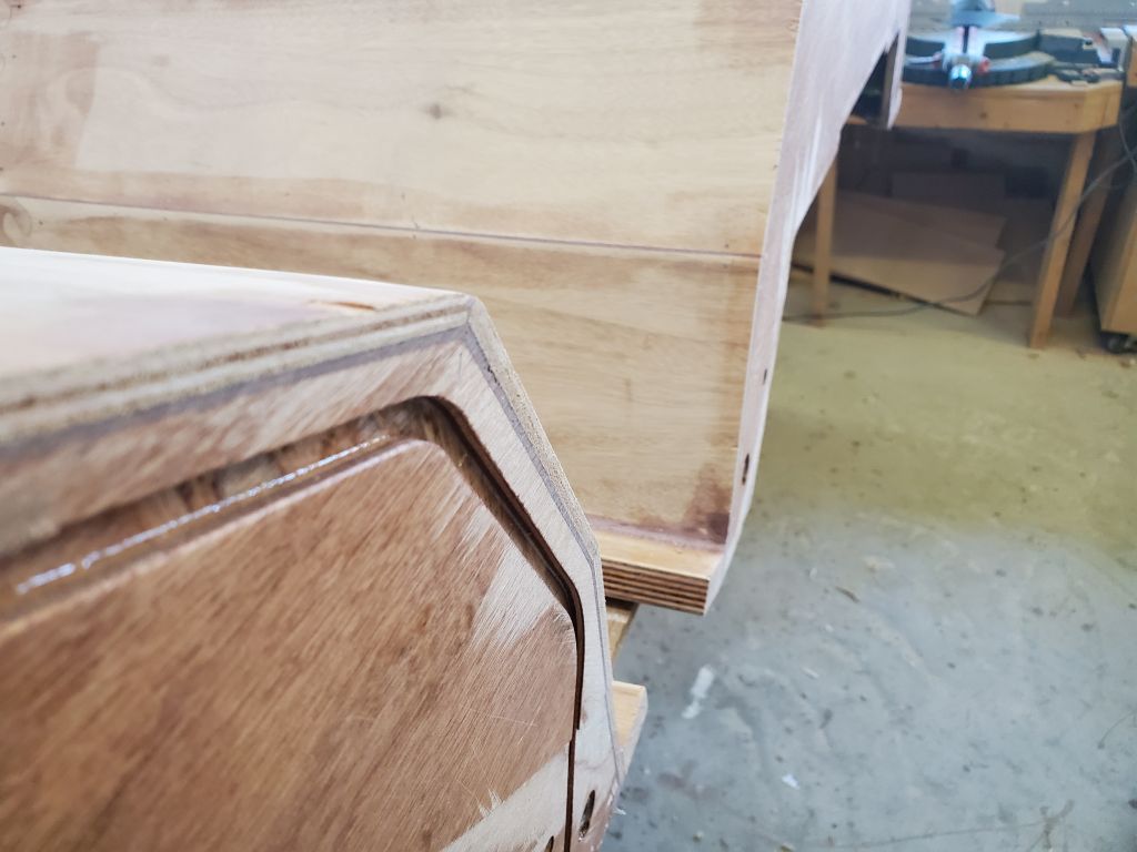
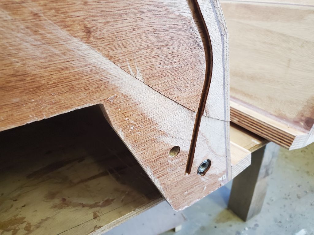
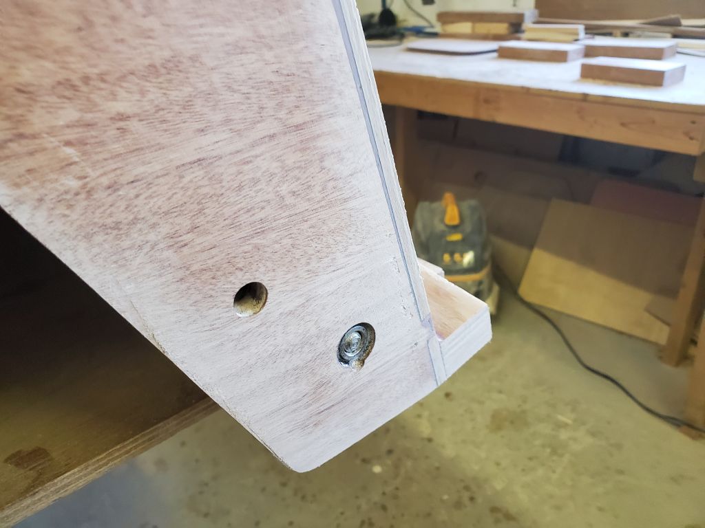
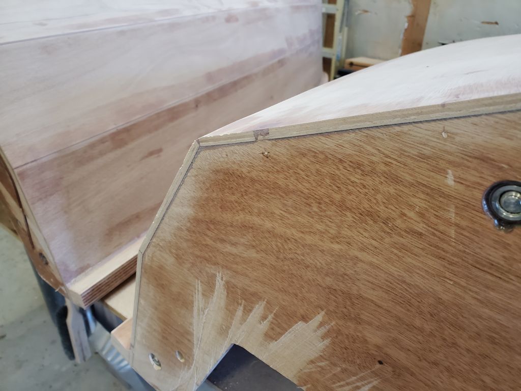
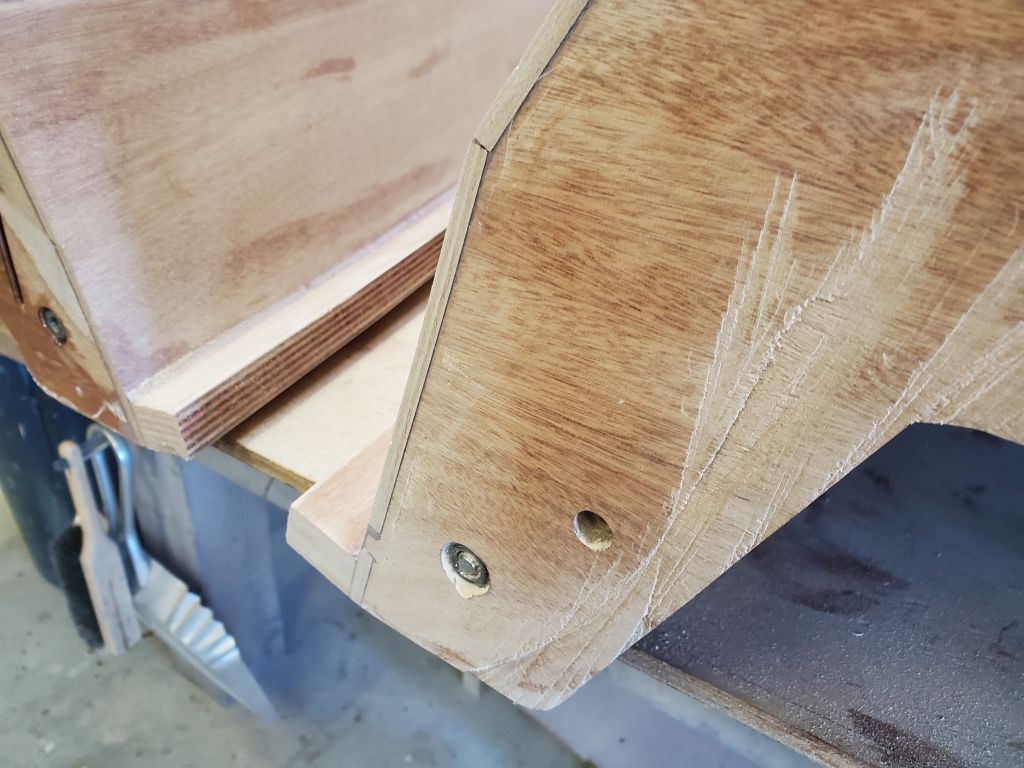
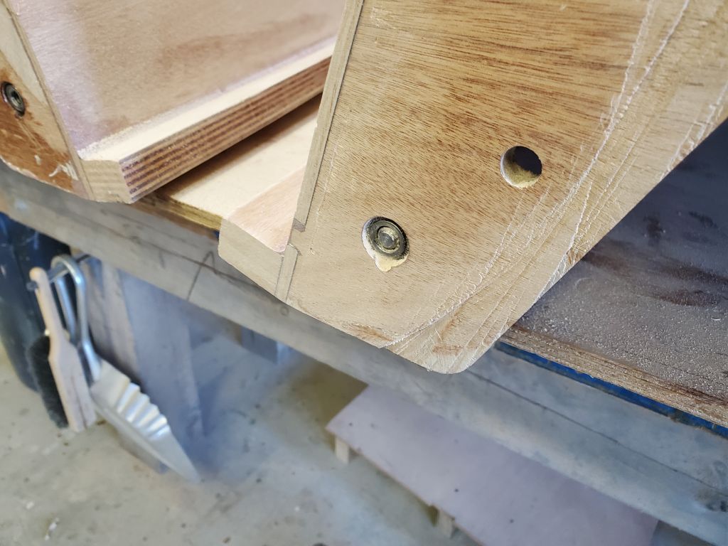
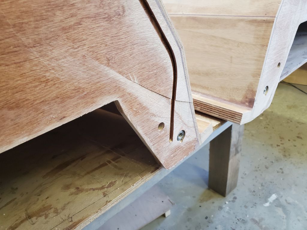
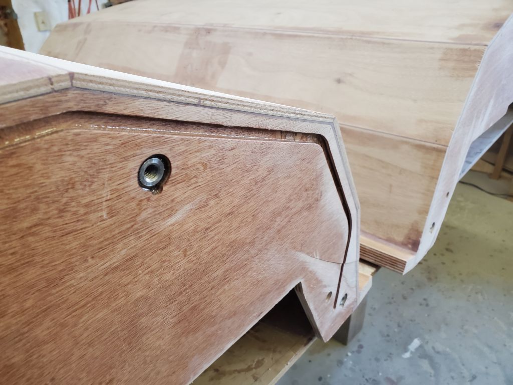
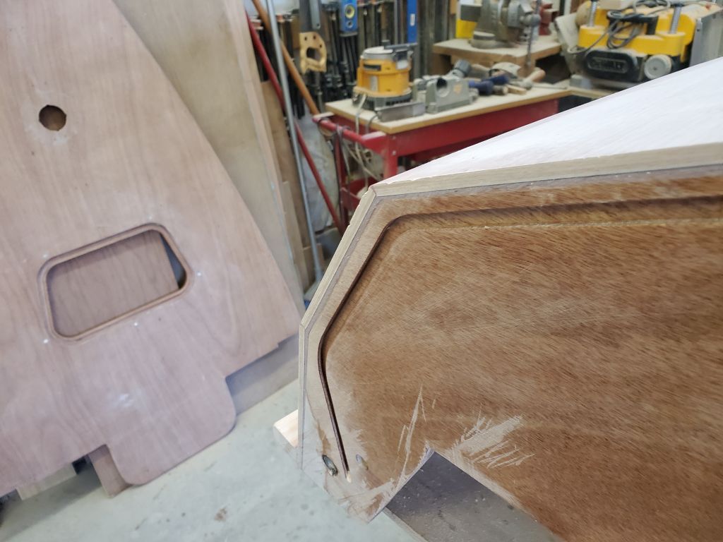
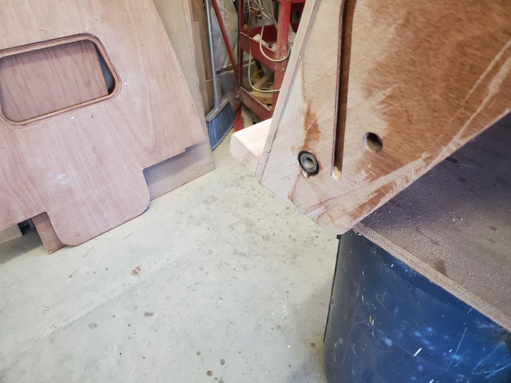
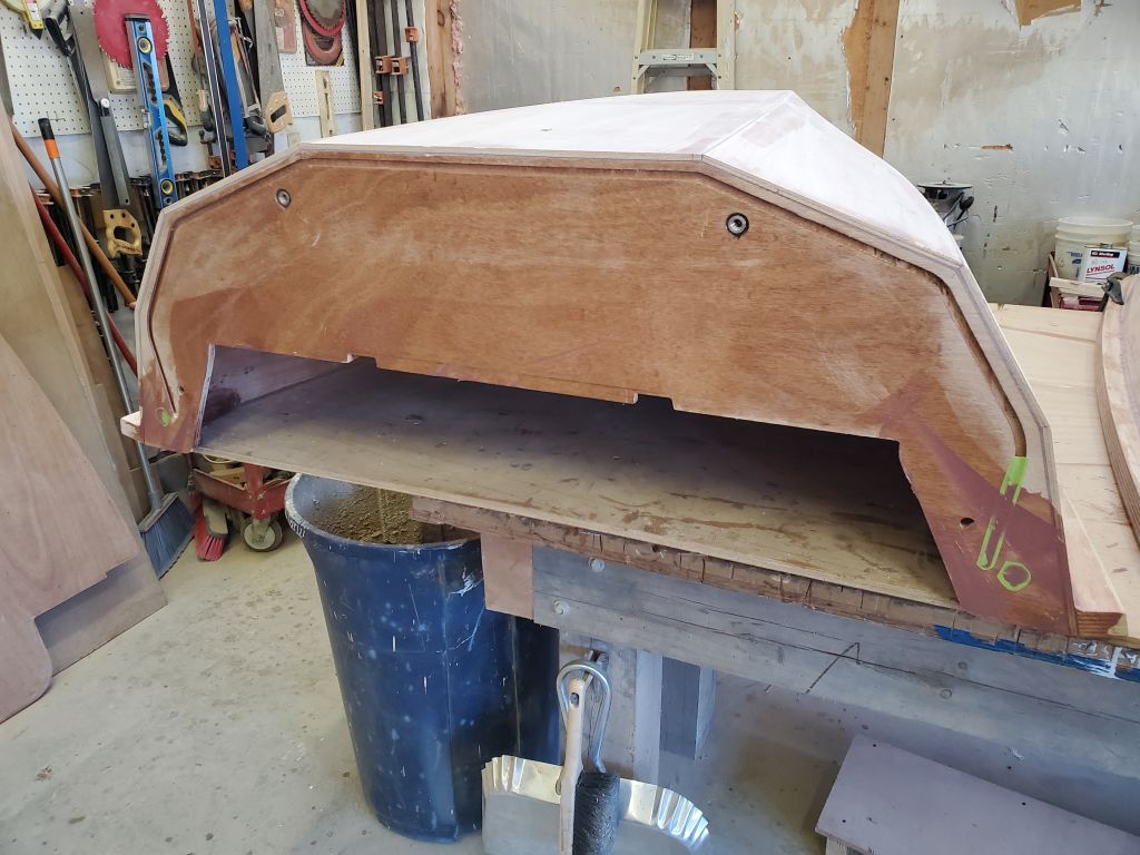
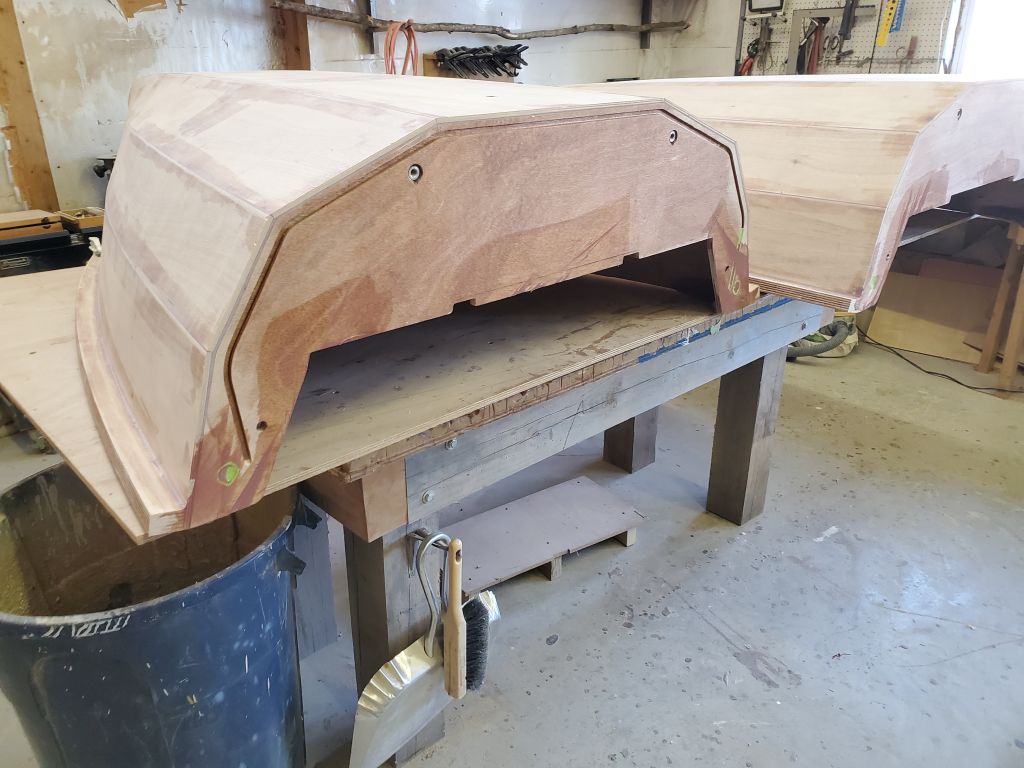
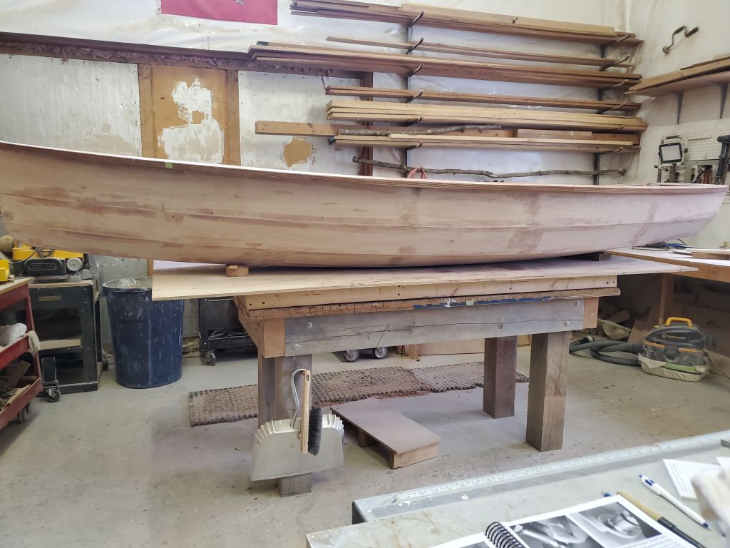
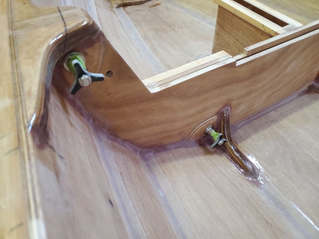
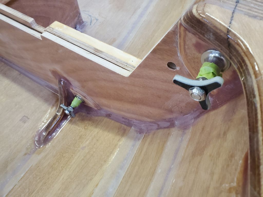
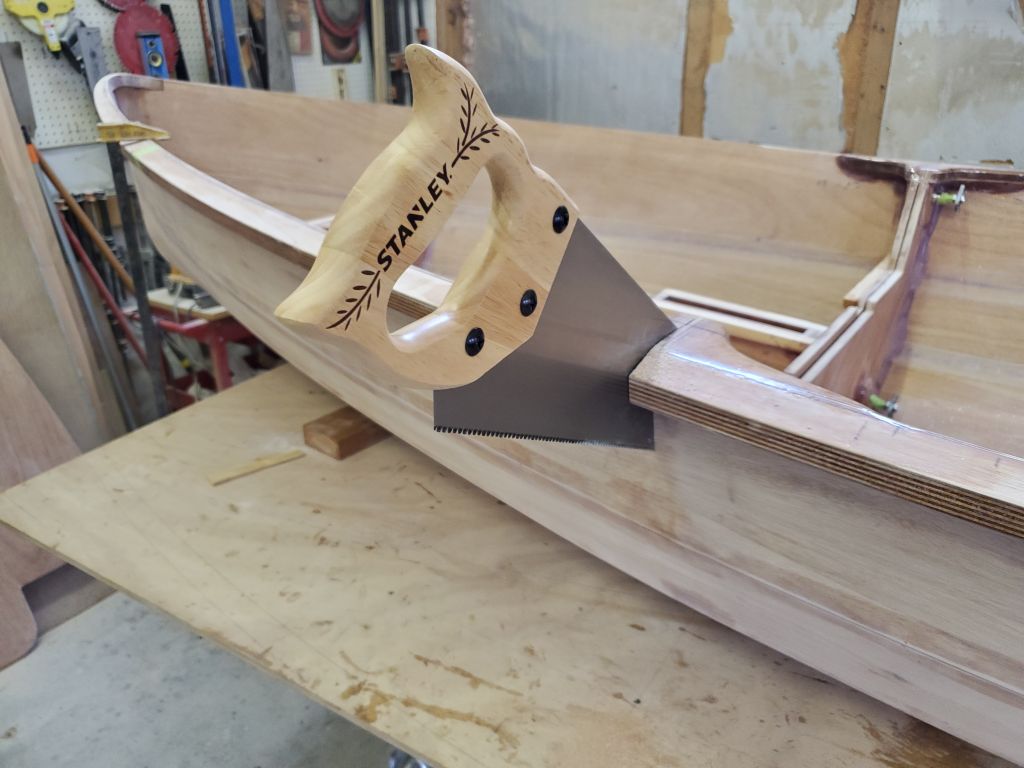
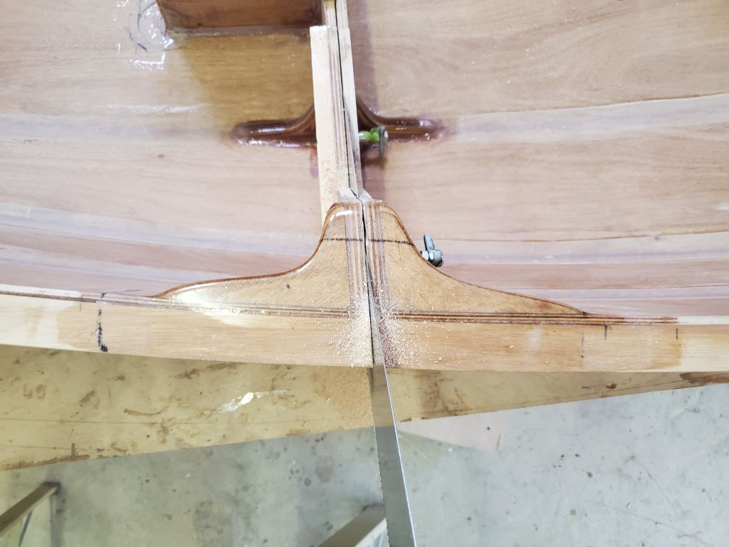
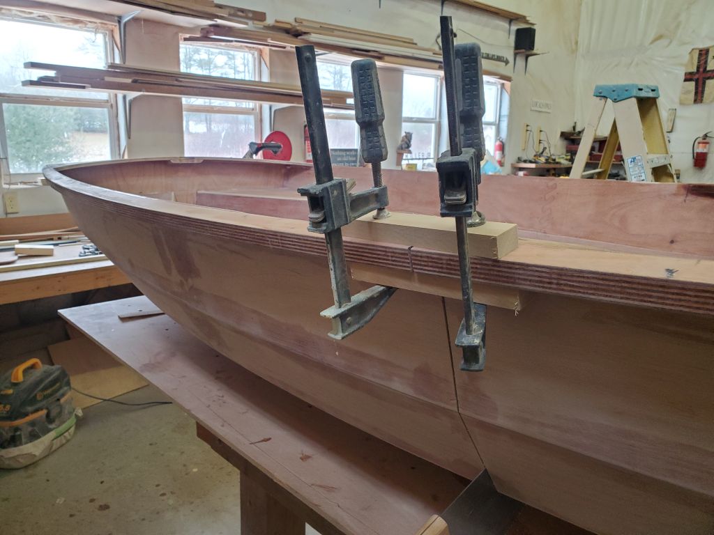
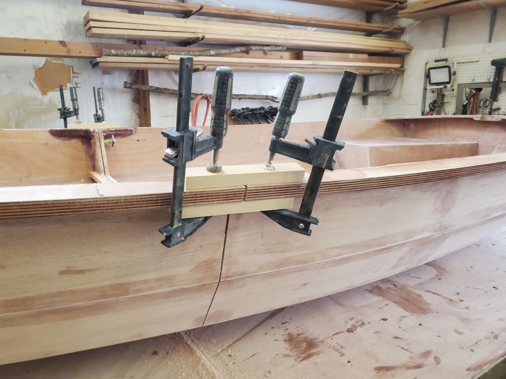
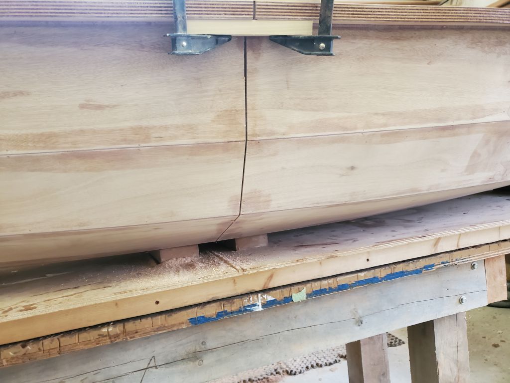
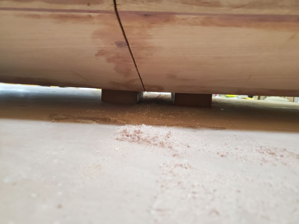
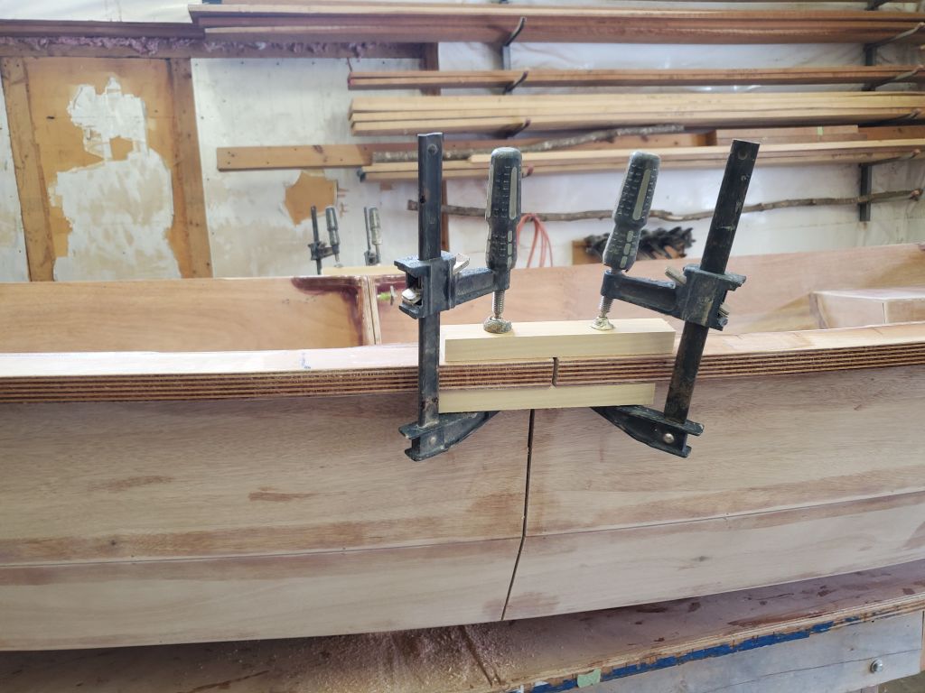
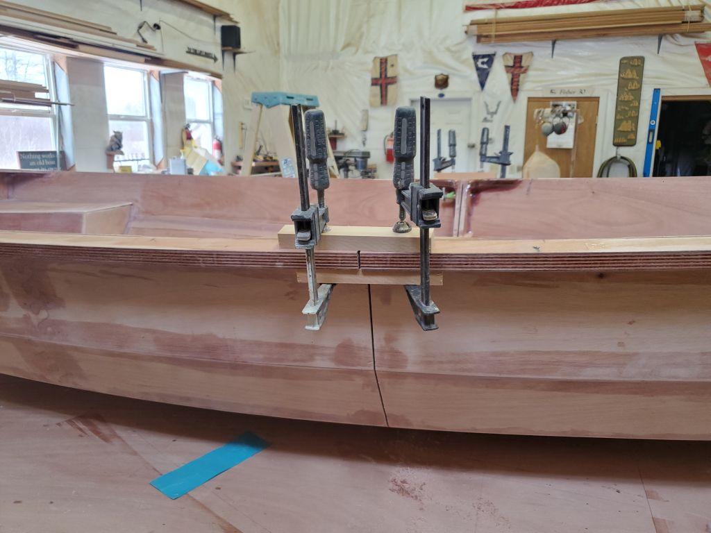
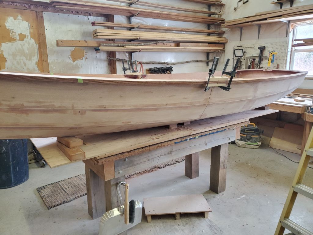
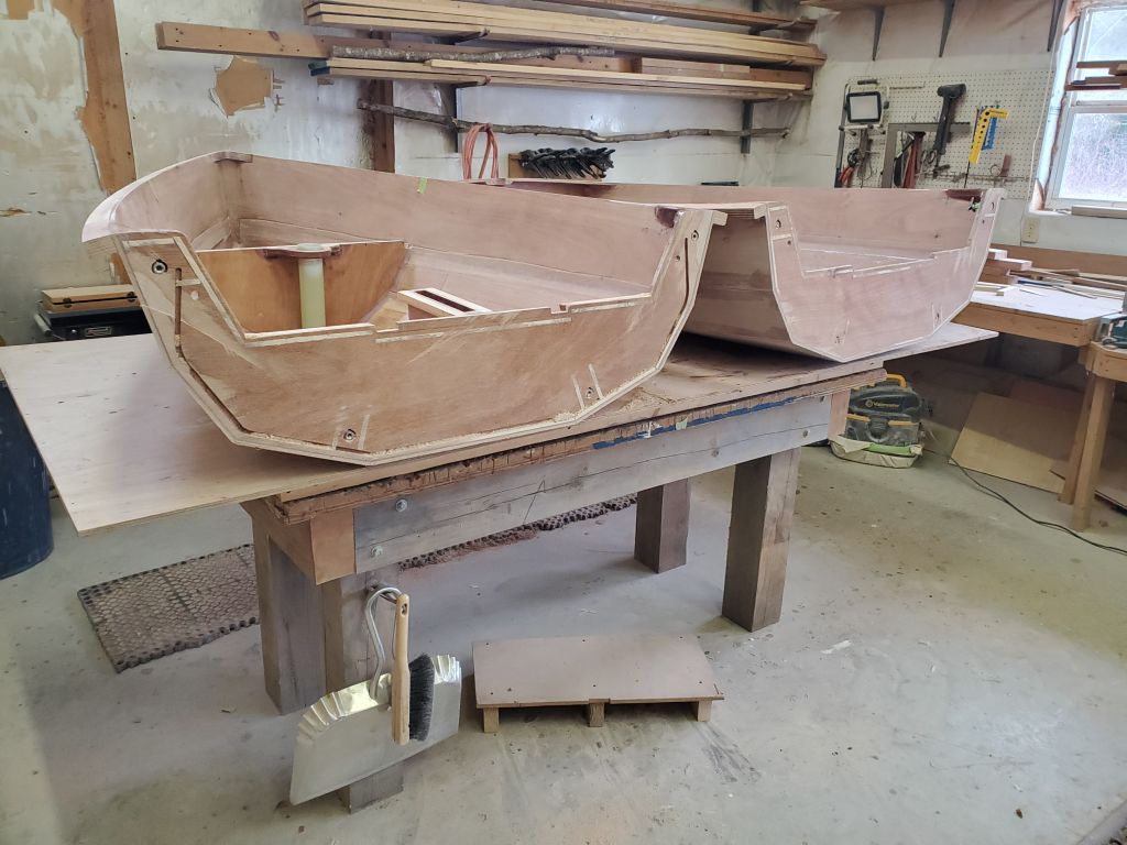
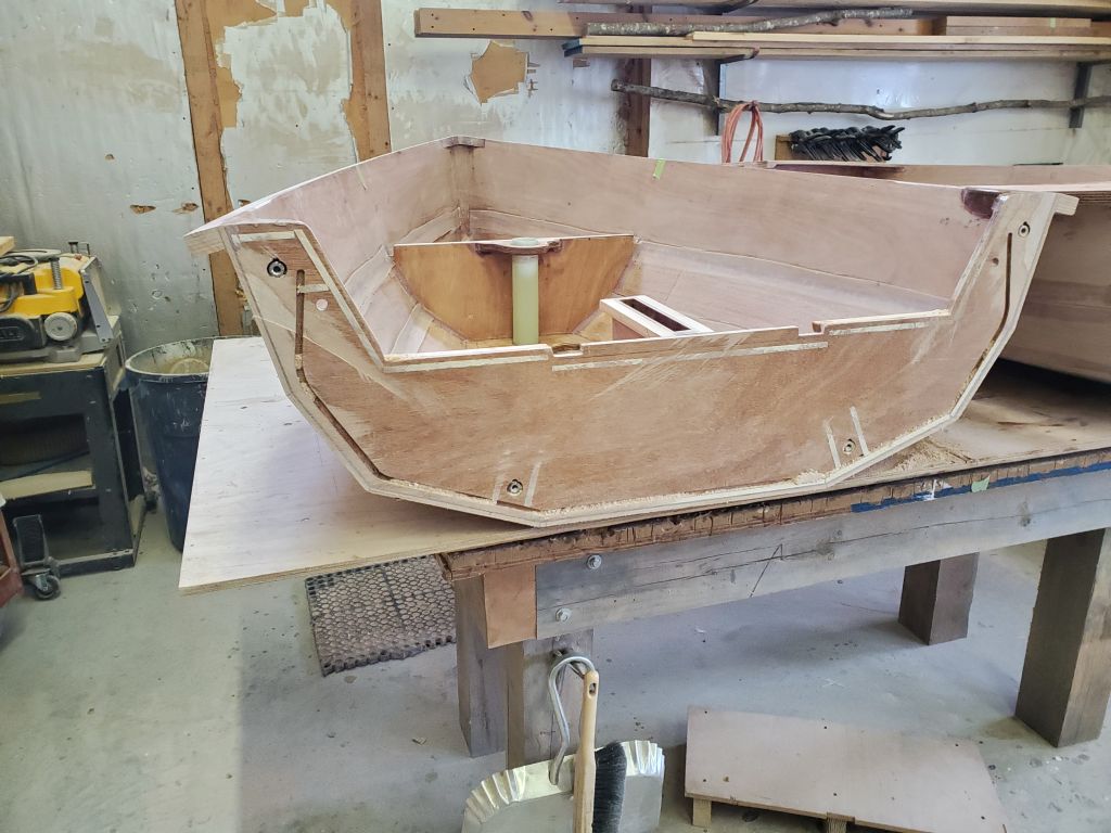
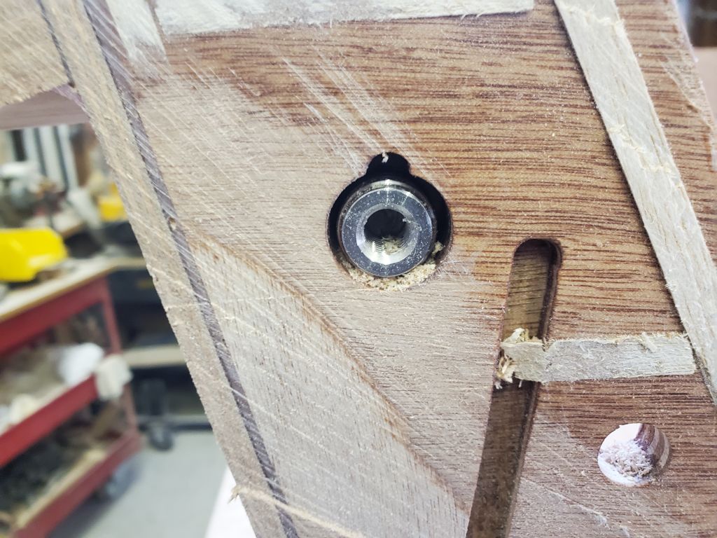
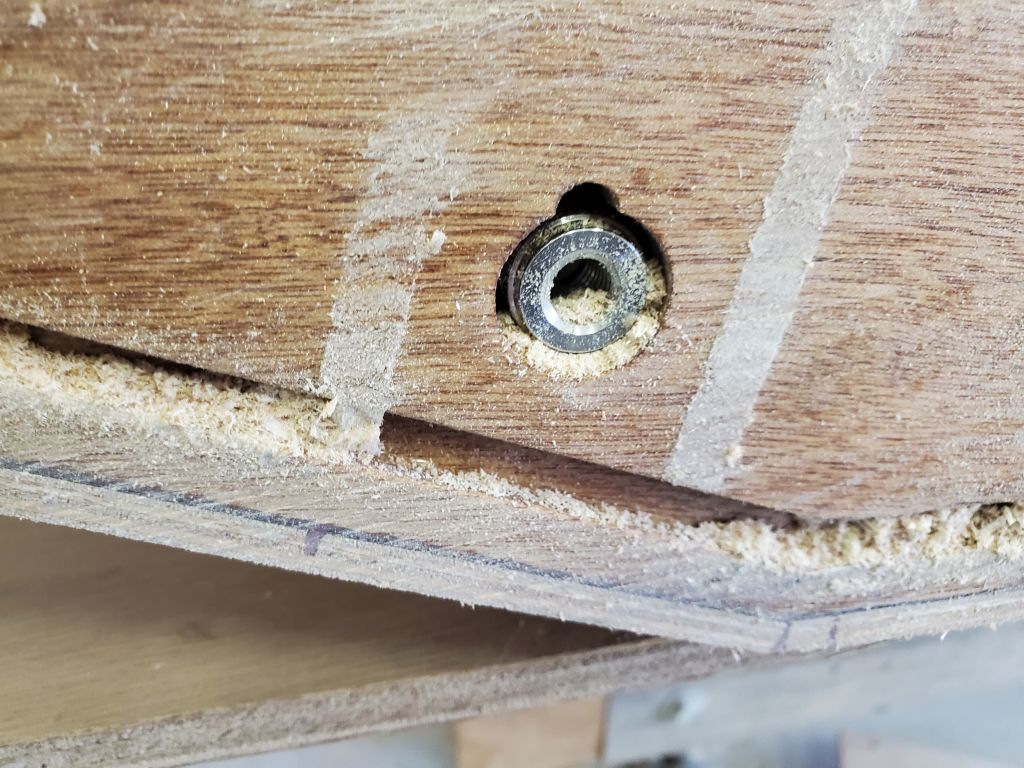
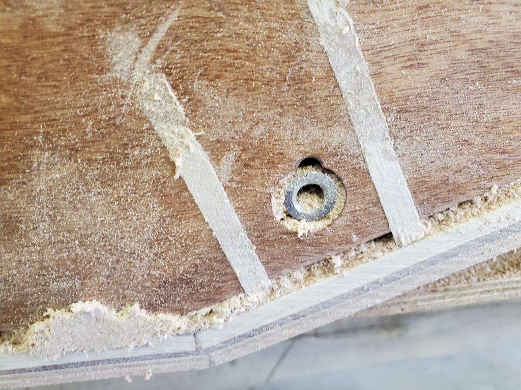
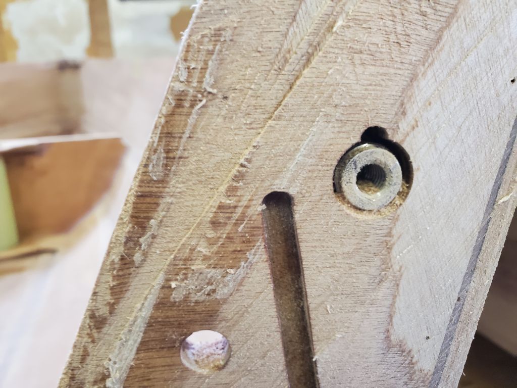
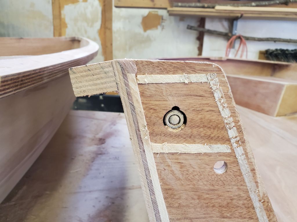
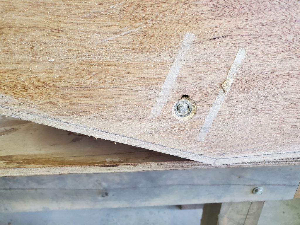
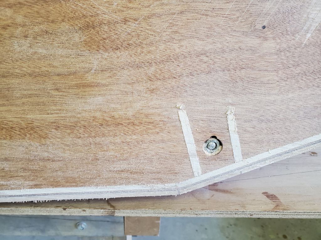
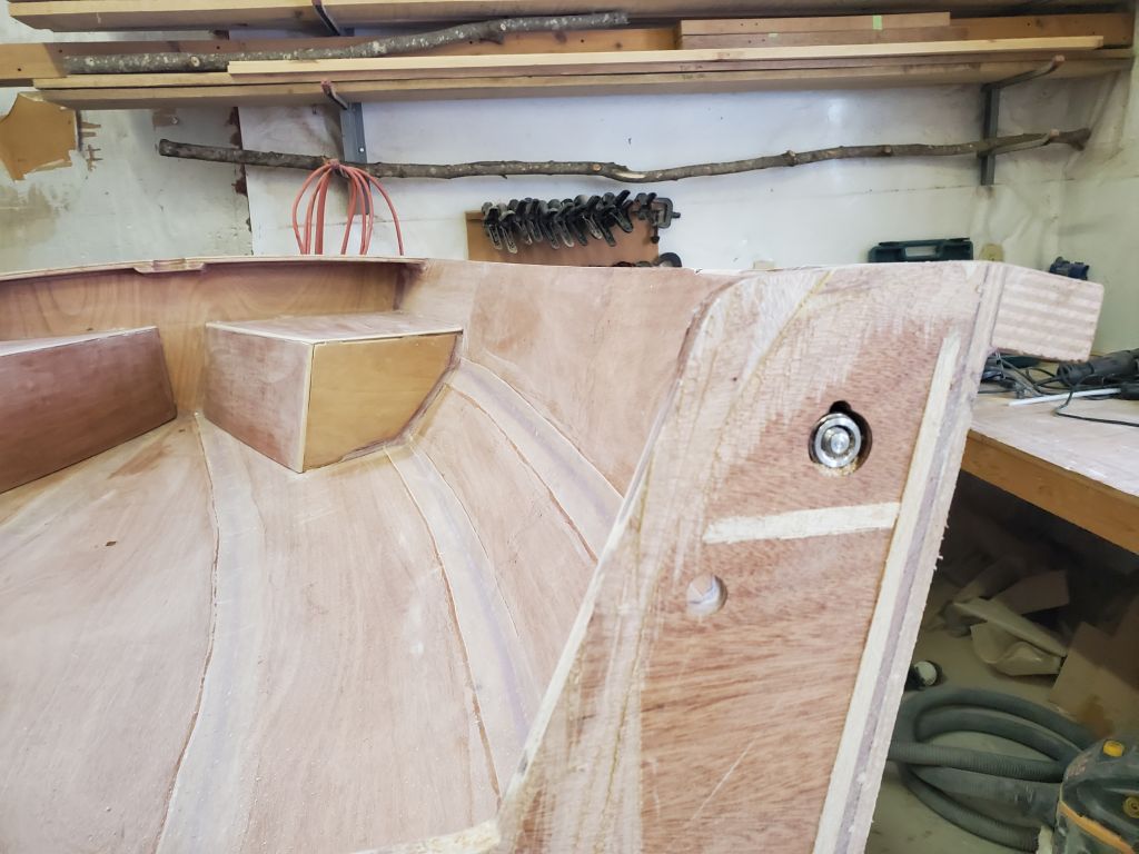
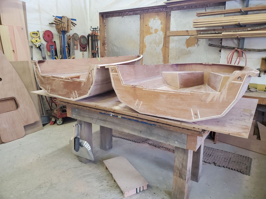
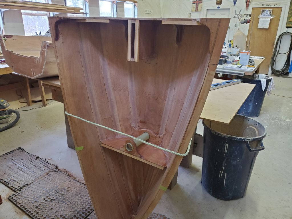
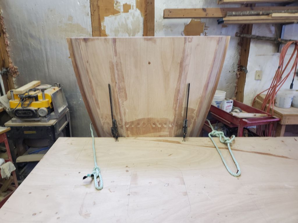
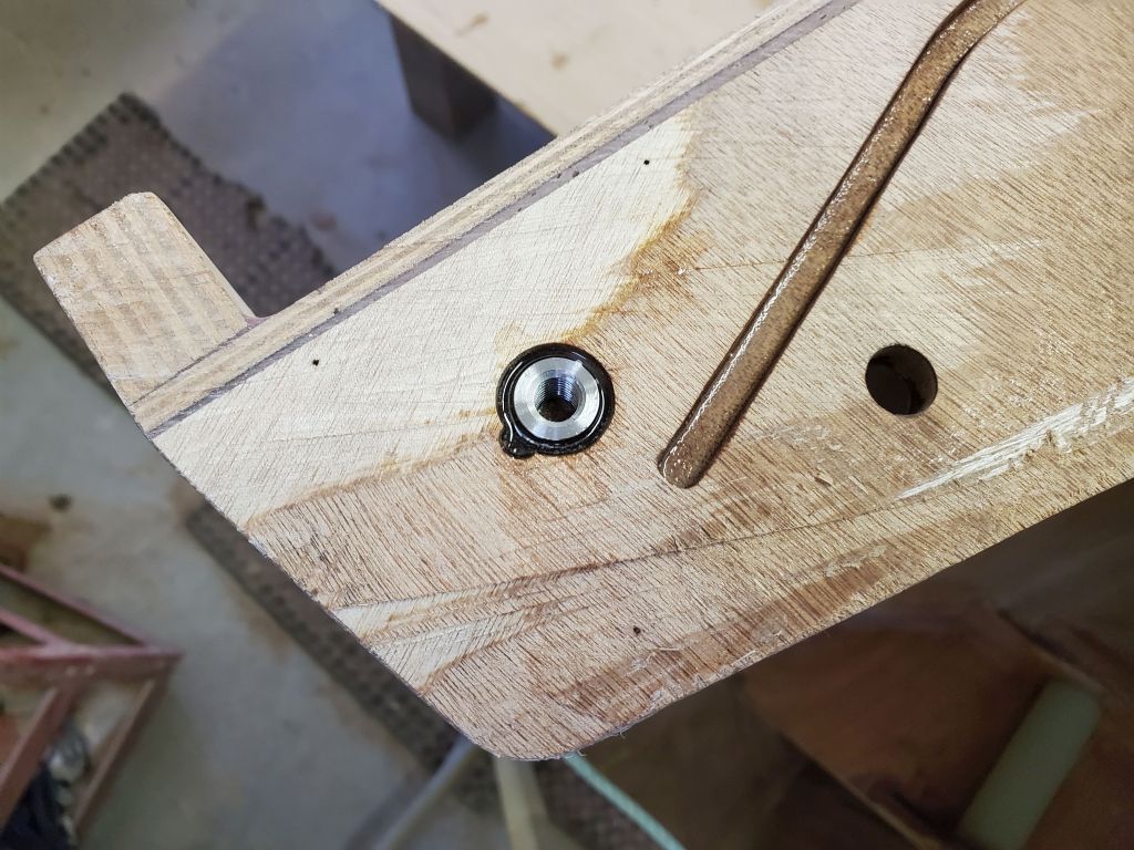
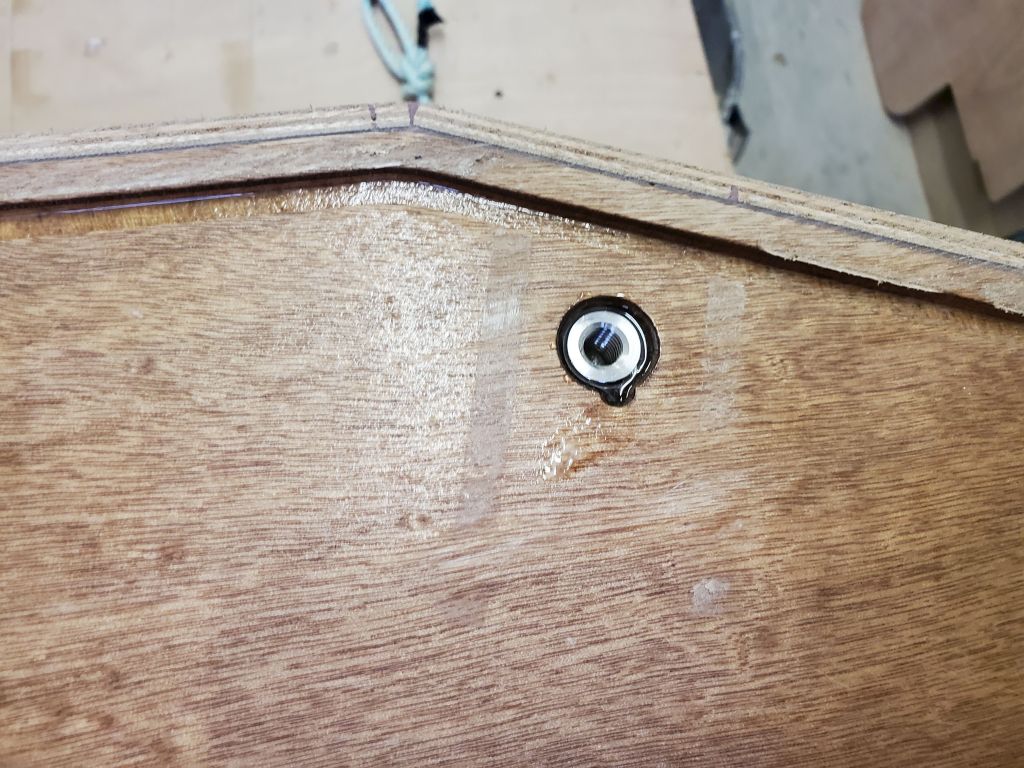
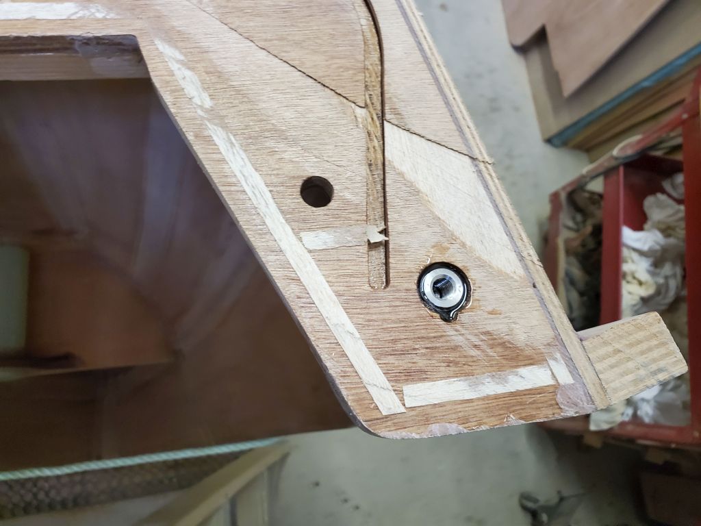
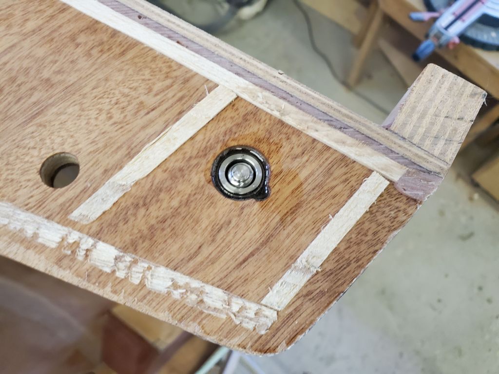
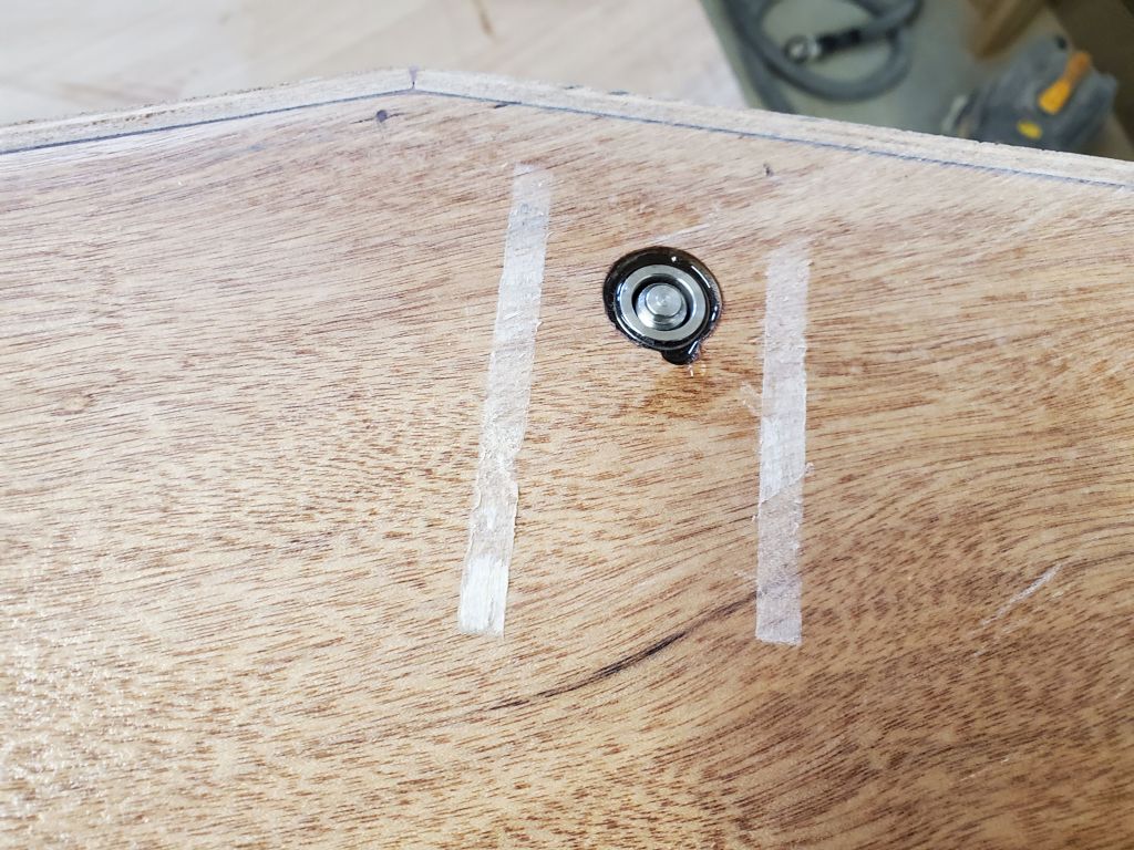
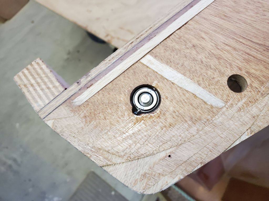
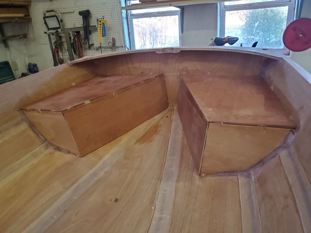
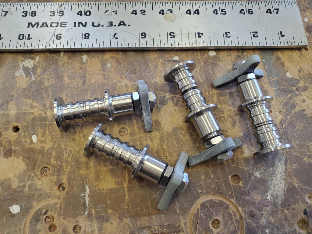
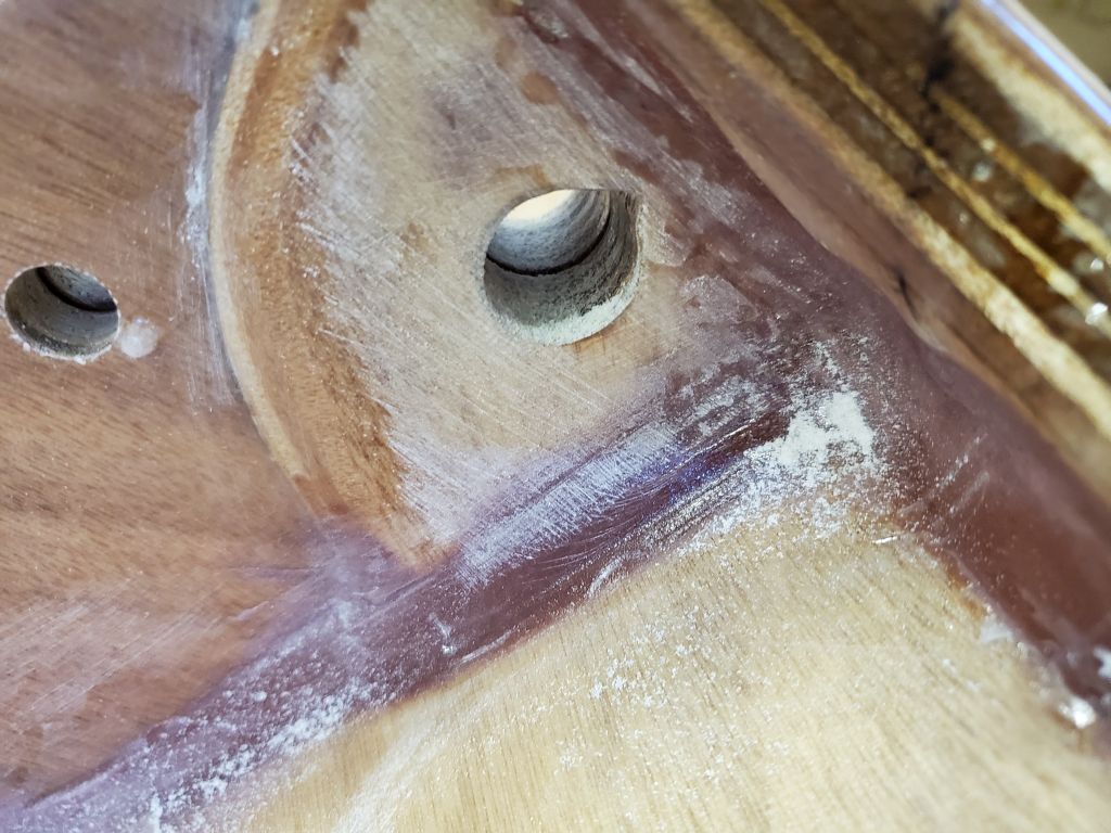
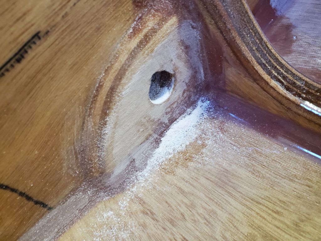
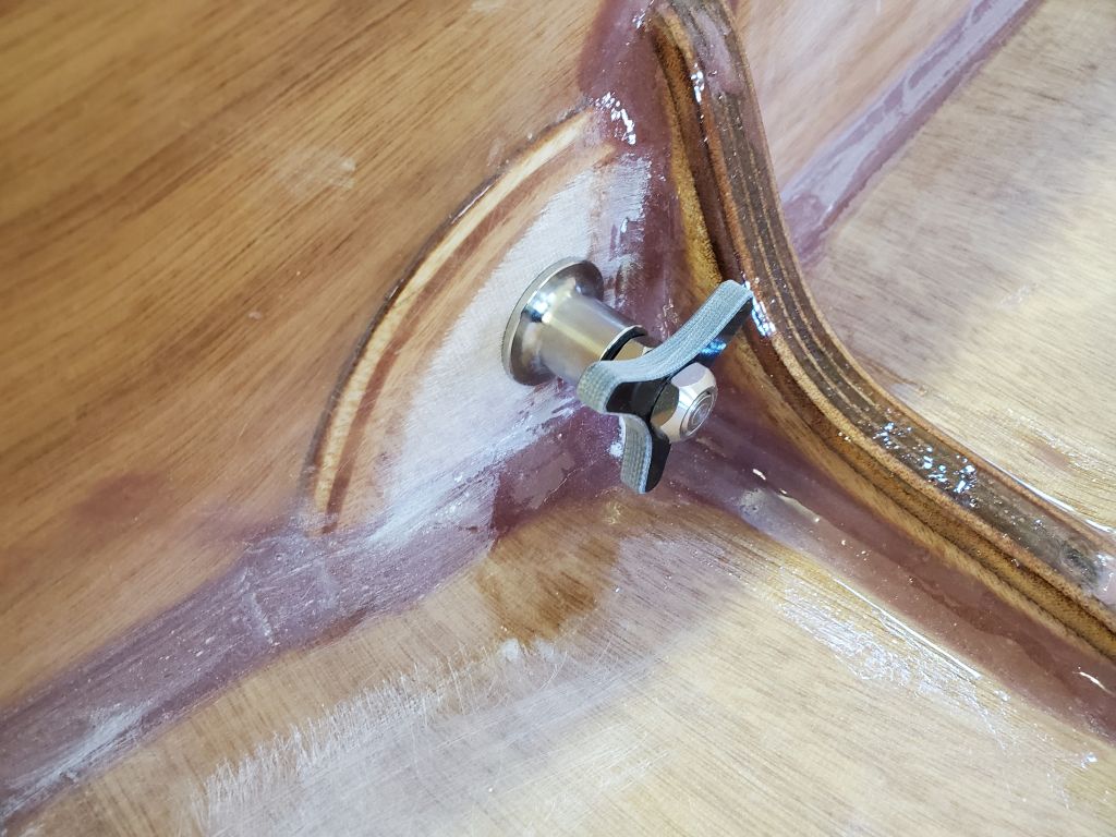
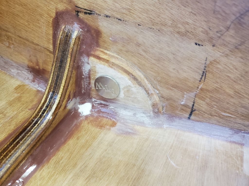
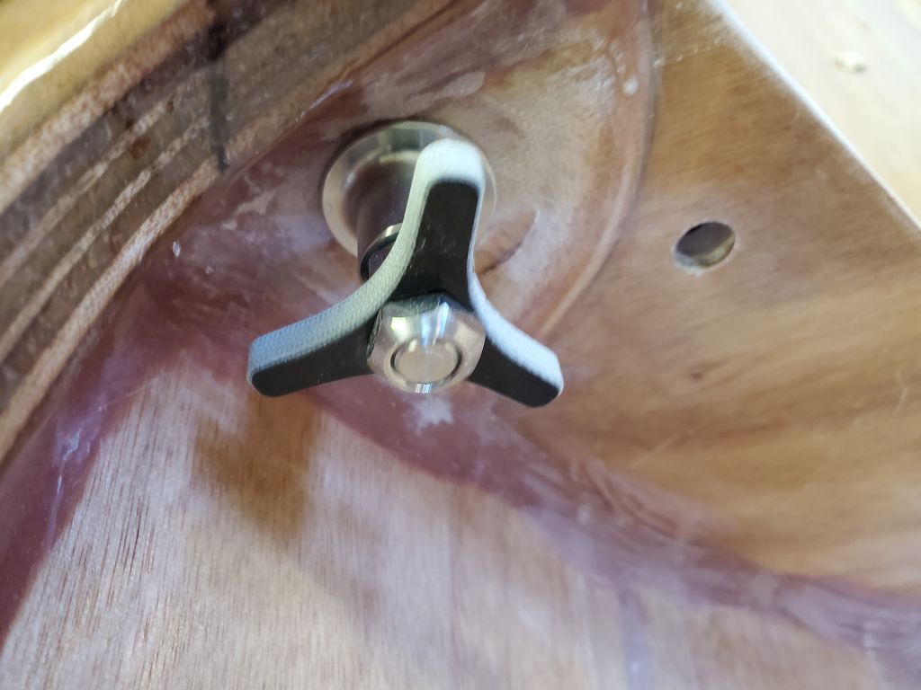
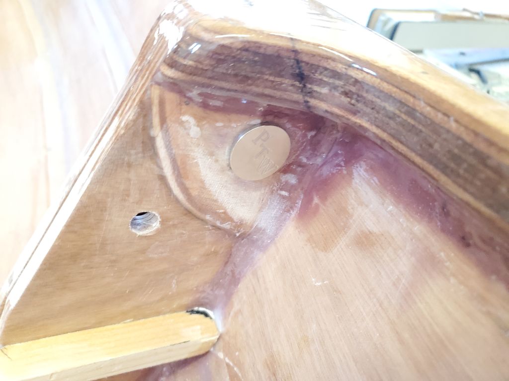
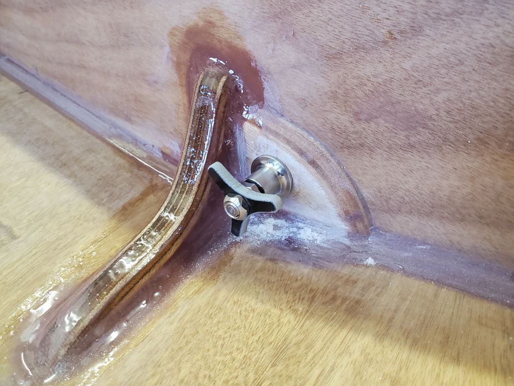
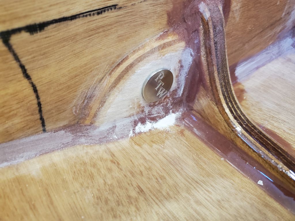
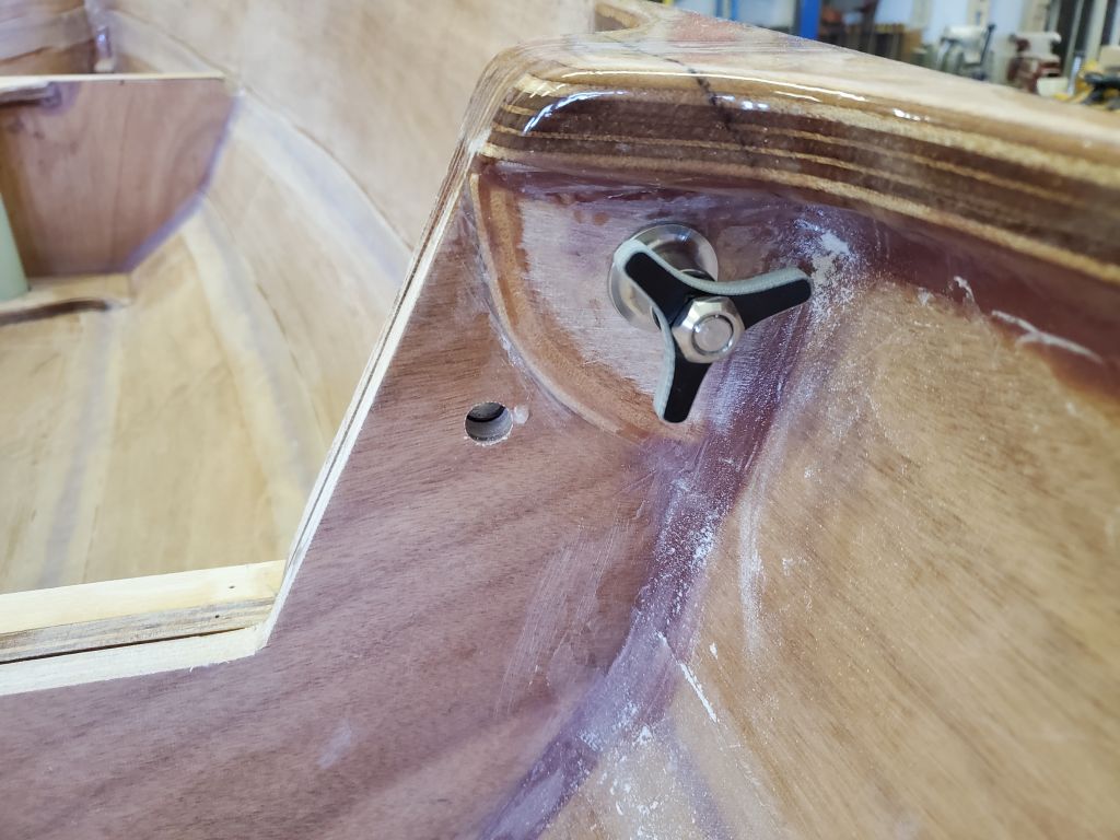
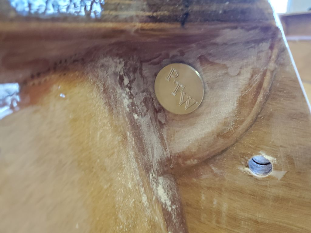
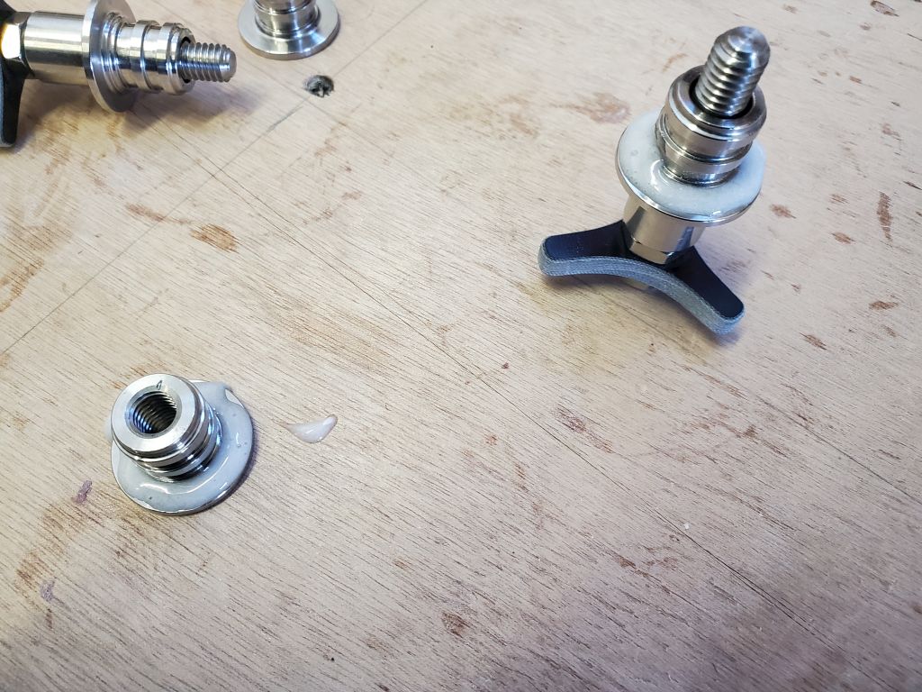
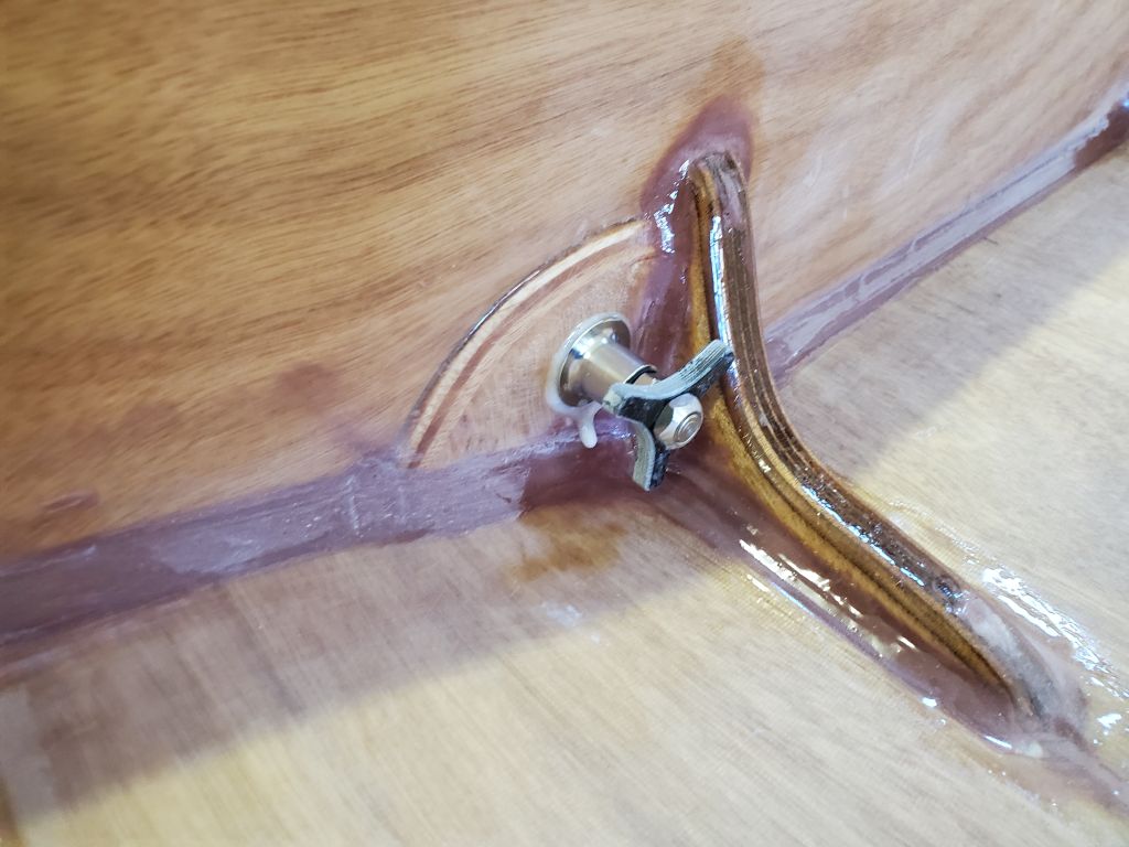
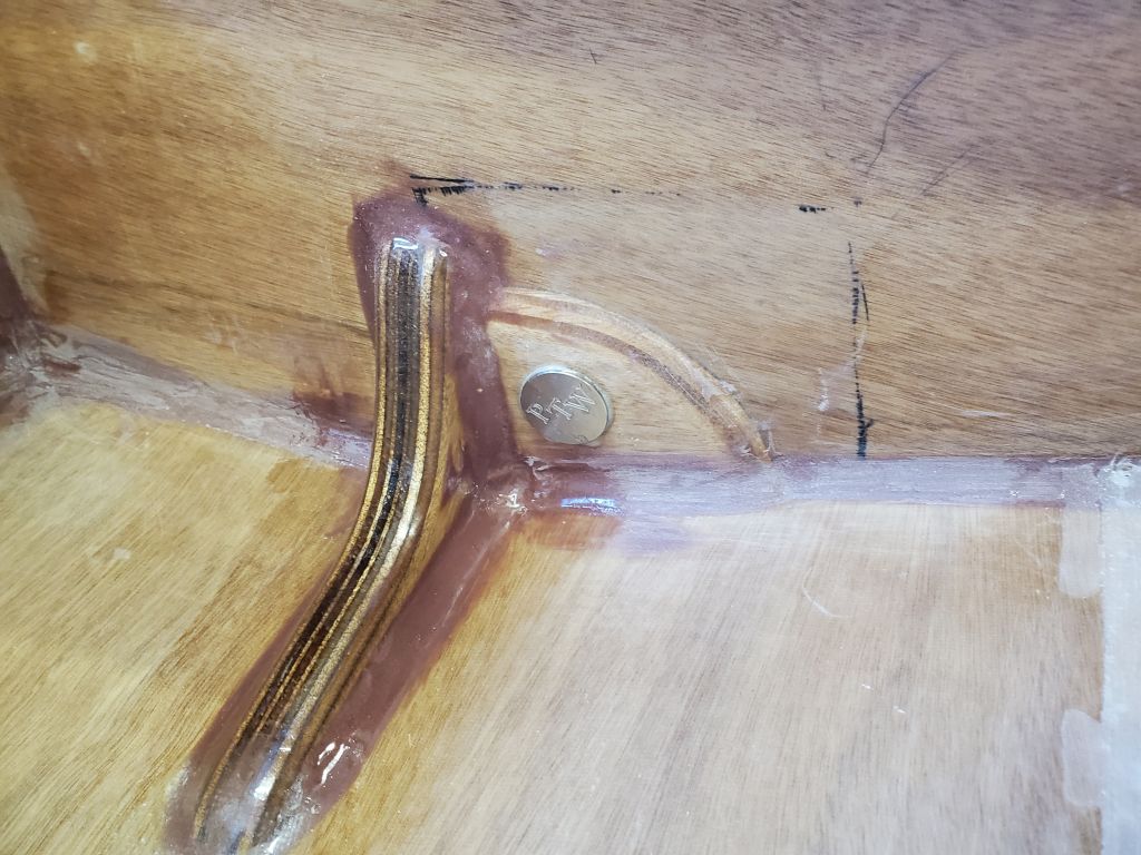
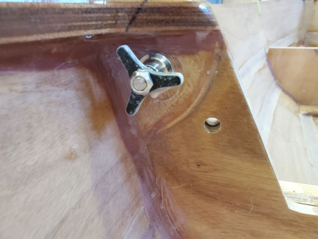
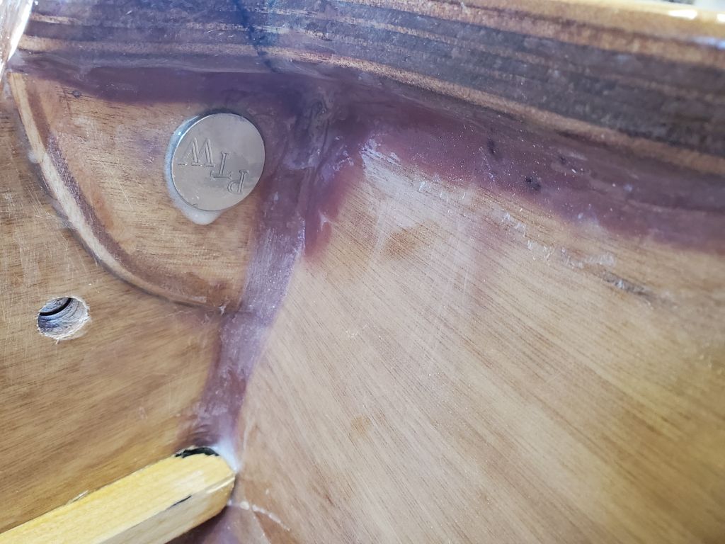
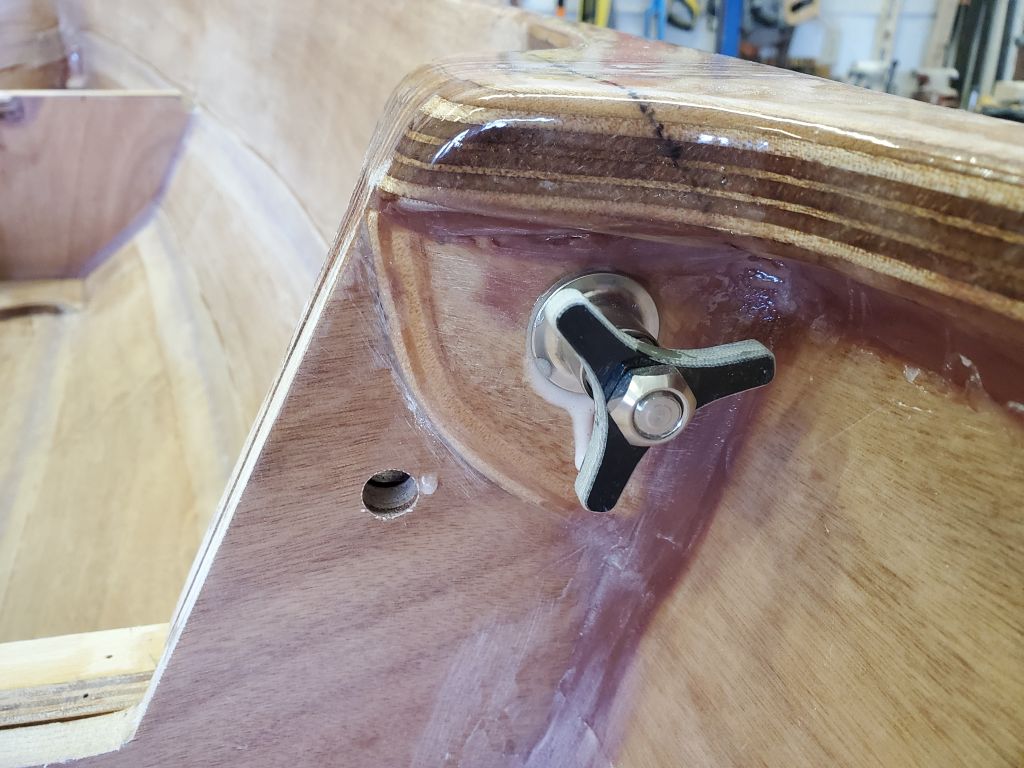
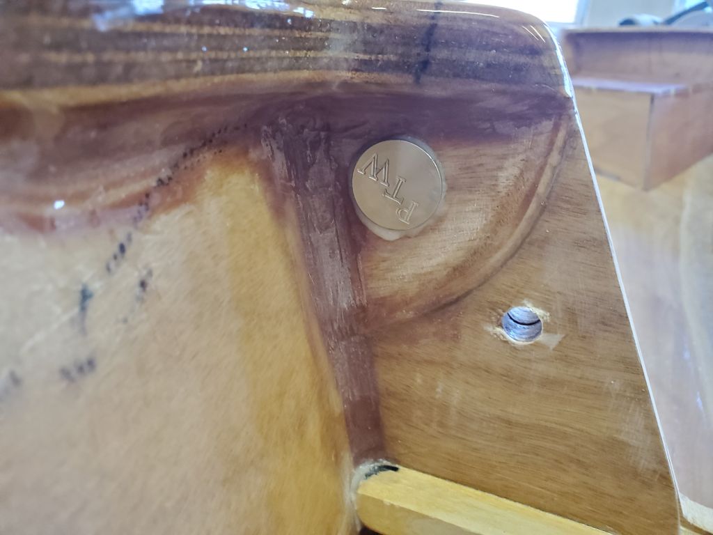
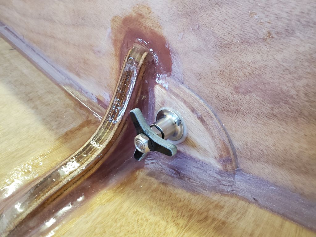
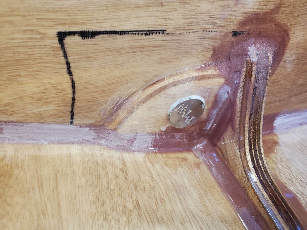
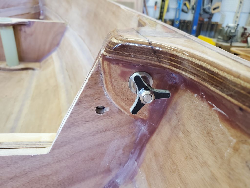
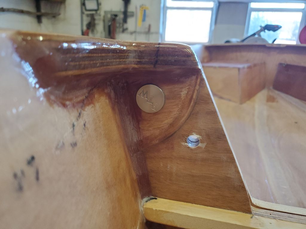
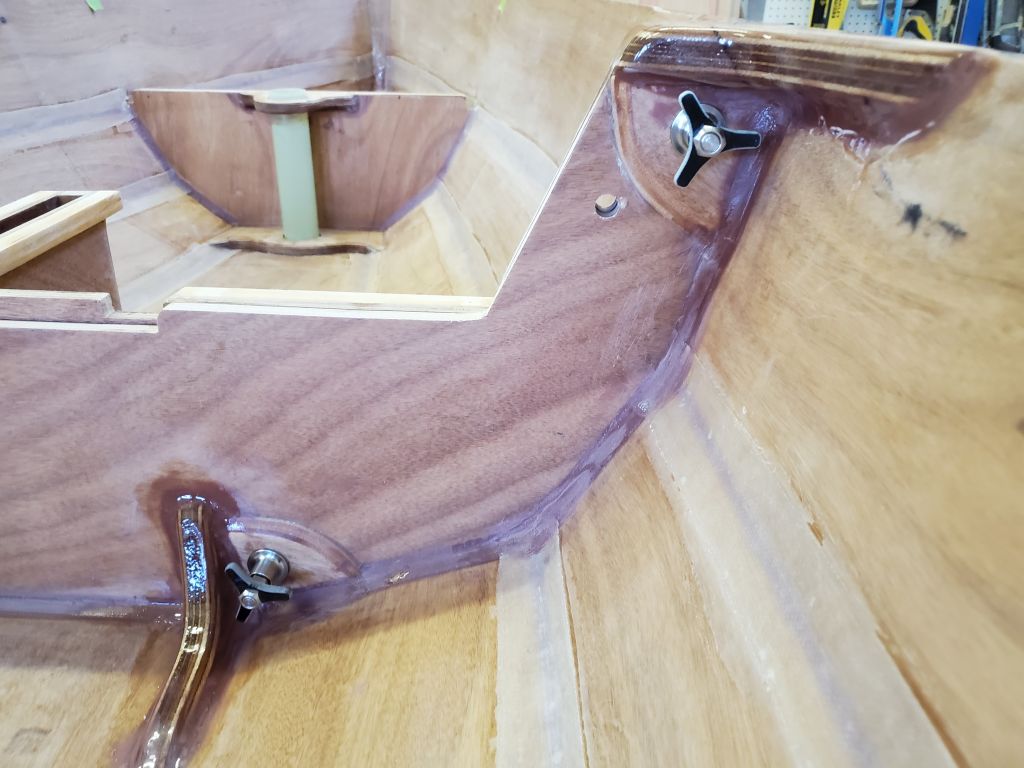
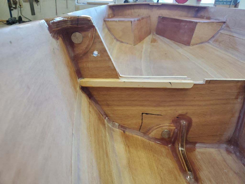
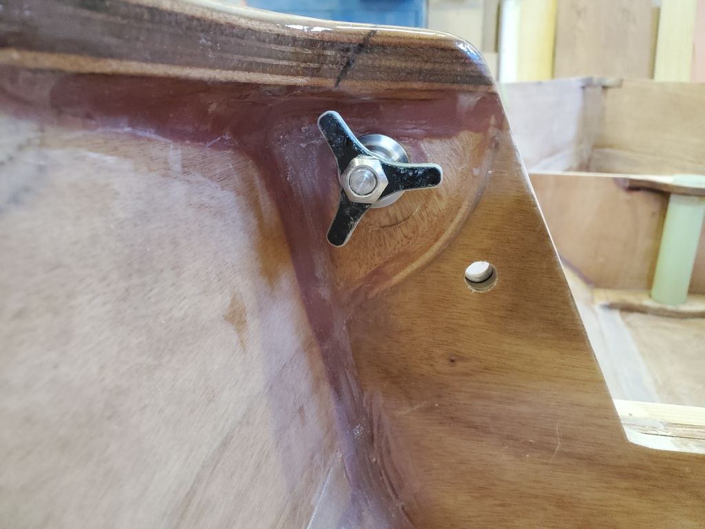
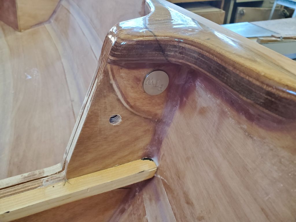
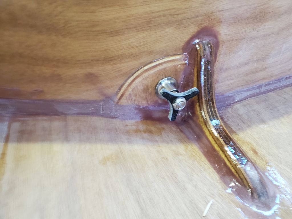
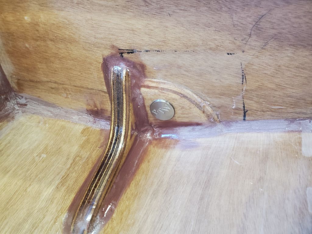
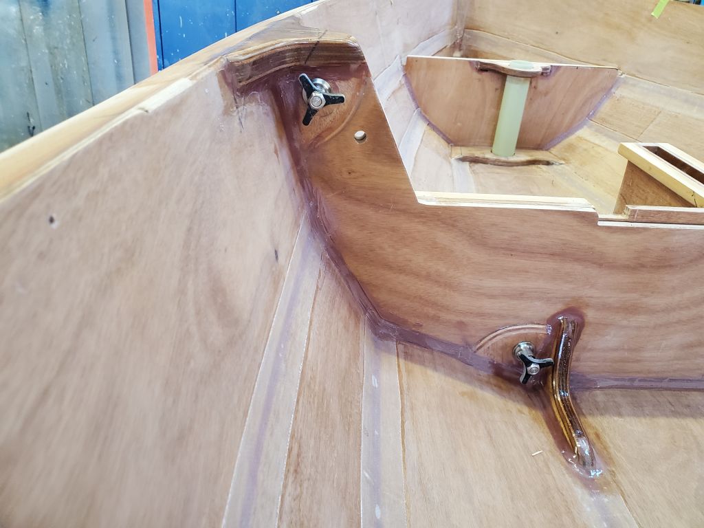
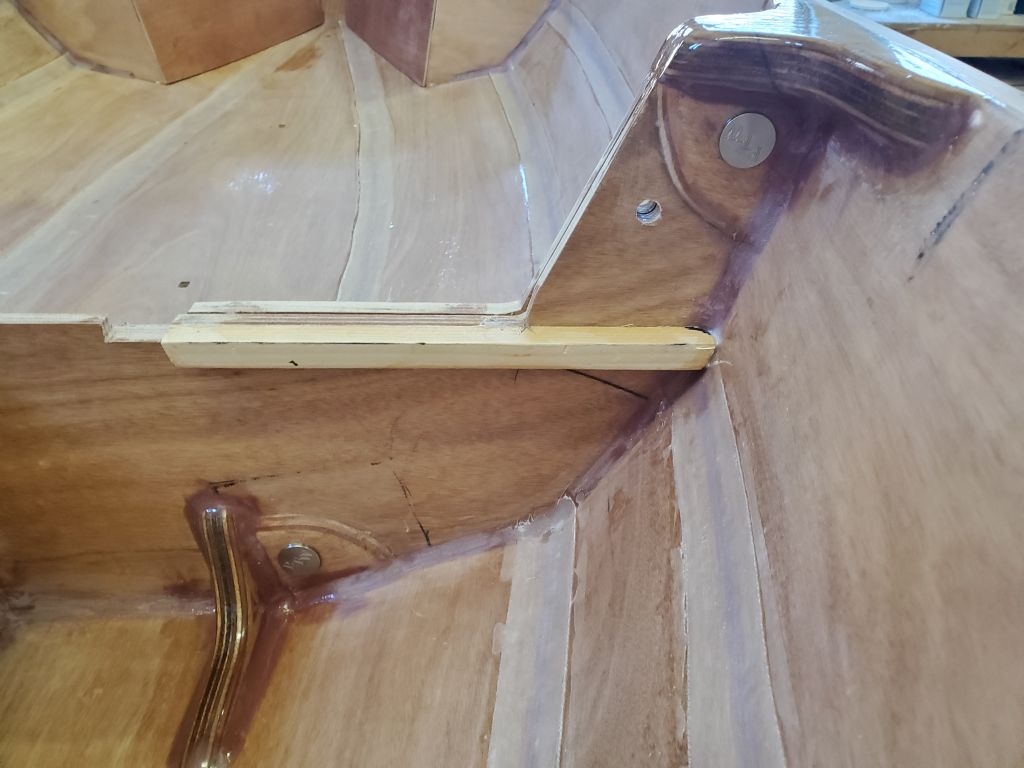
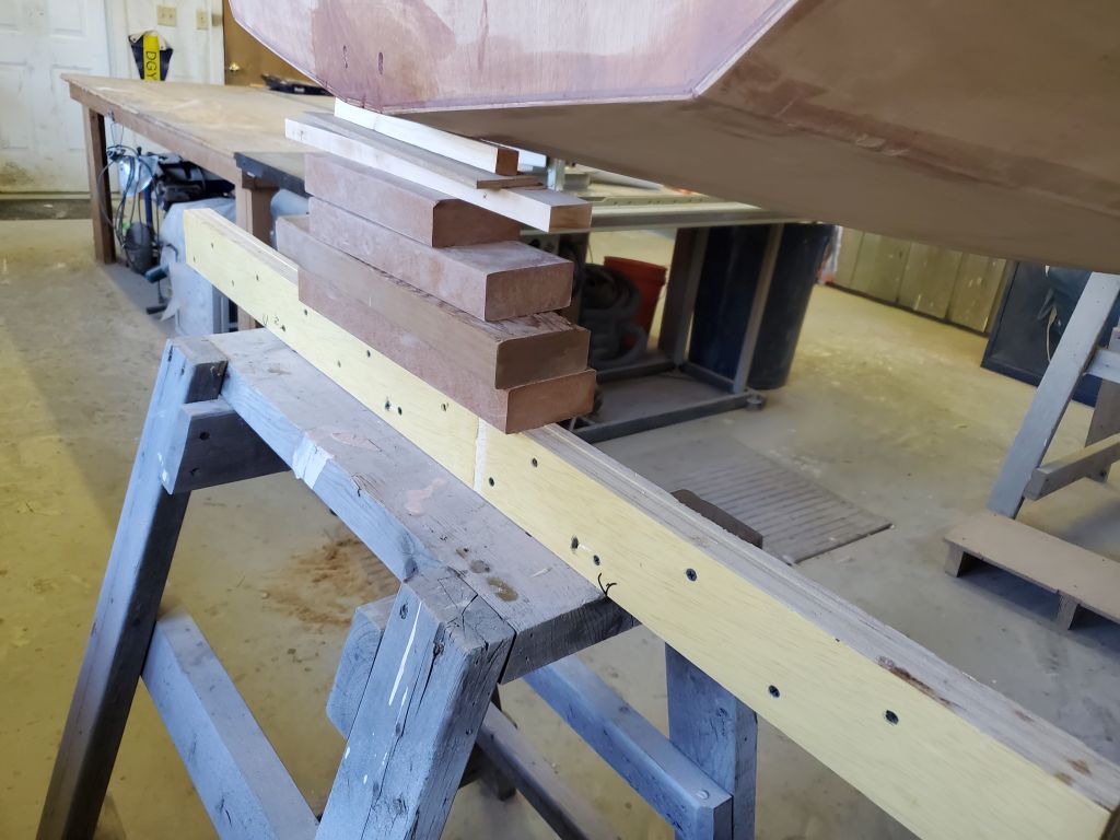
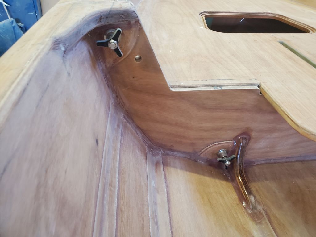
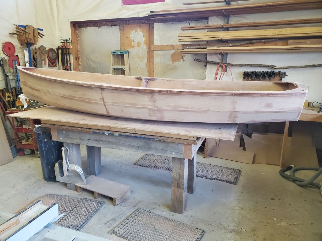
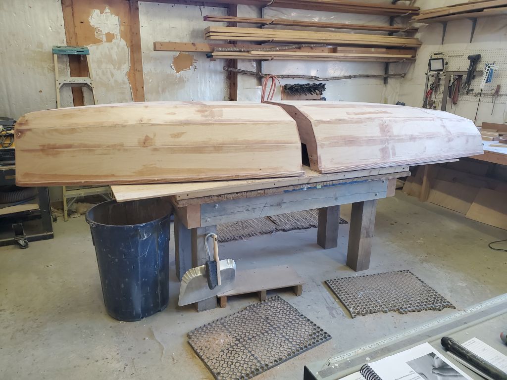
Next, I reinstalled the mating hardware and connected the two boat halves together again for the first time since cutting the boat. I did this on the benchtop, supporting the ends with some blocking as needed to bring the bulkheads flat together so I could start to engage the threads of the four connecting bolts. It took a little doing to get things aligned, but before long the boat was reconnected. Sometime later in the build, I’d install some alignment hardware that would make this process foolproof on the water.
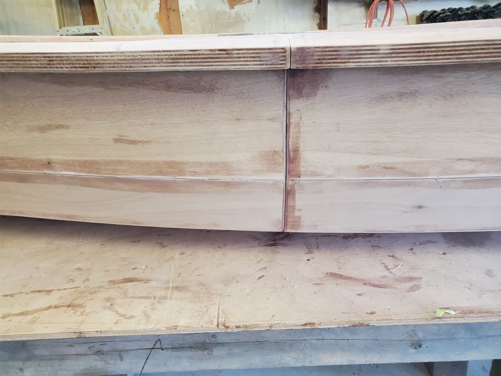
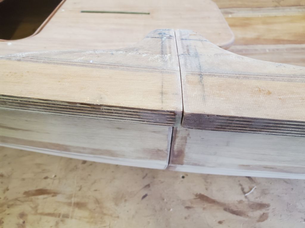
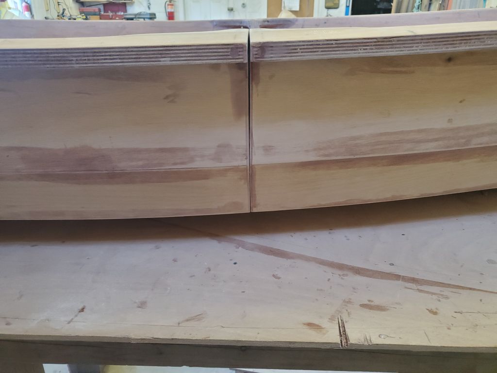
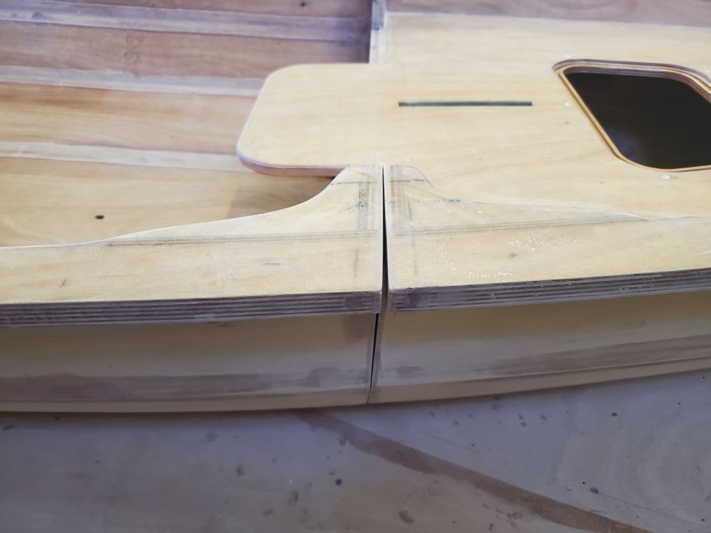
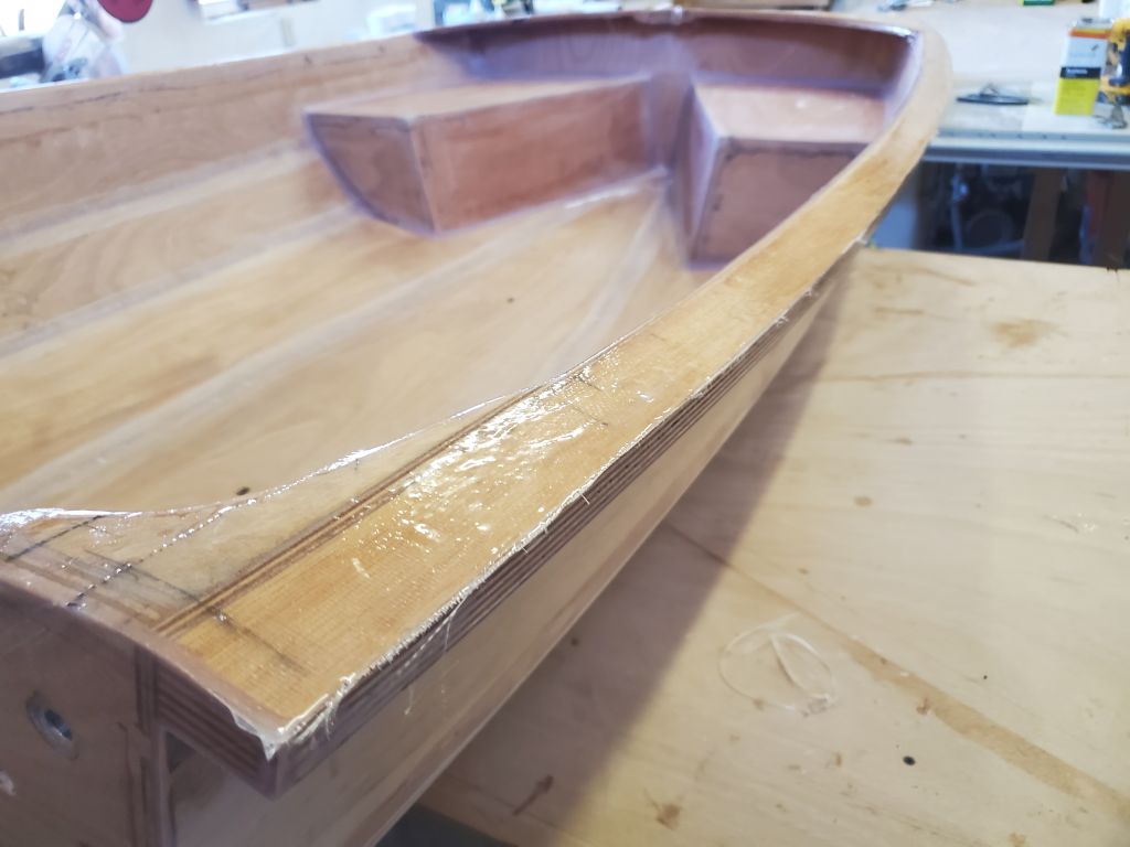
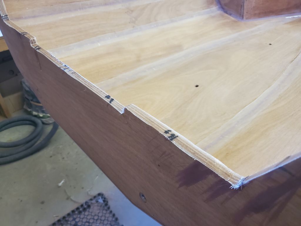
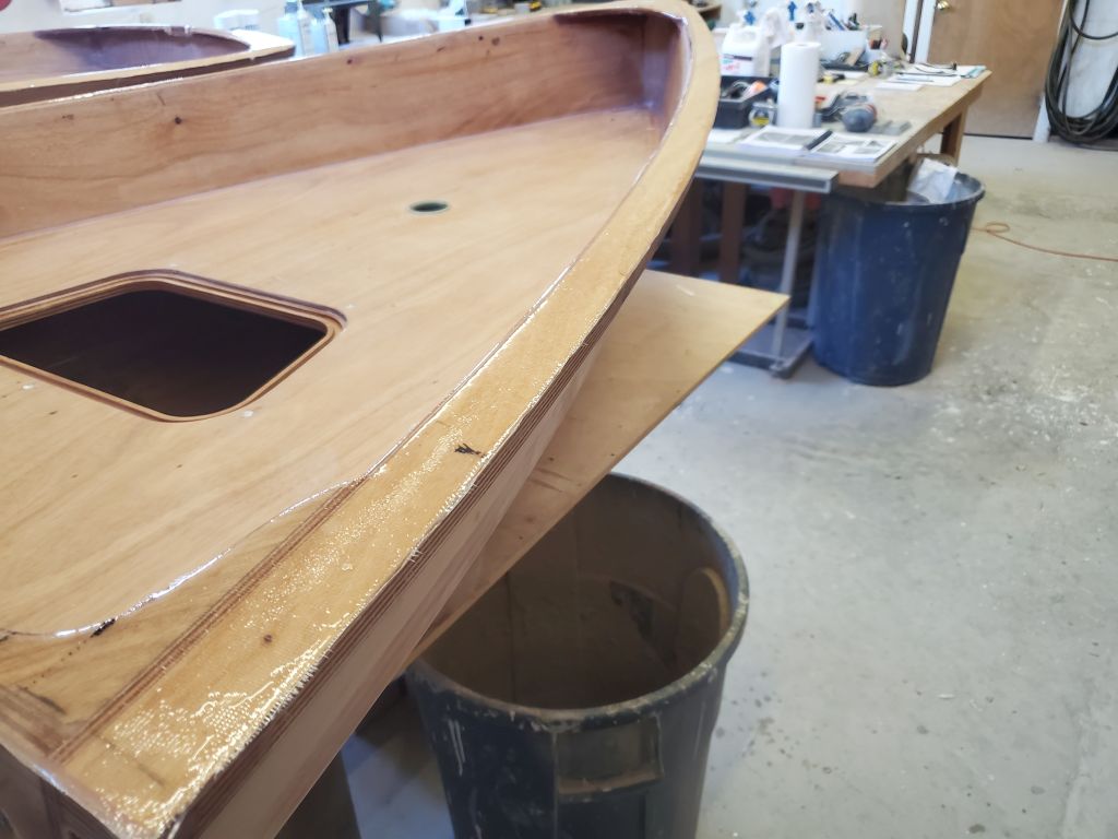
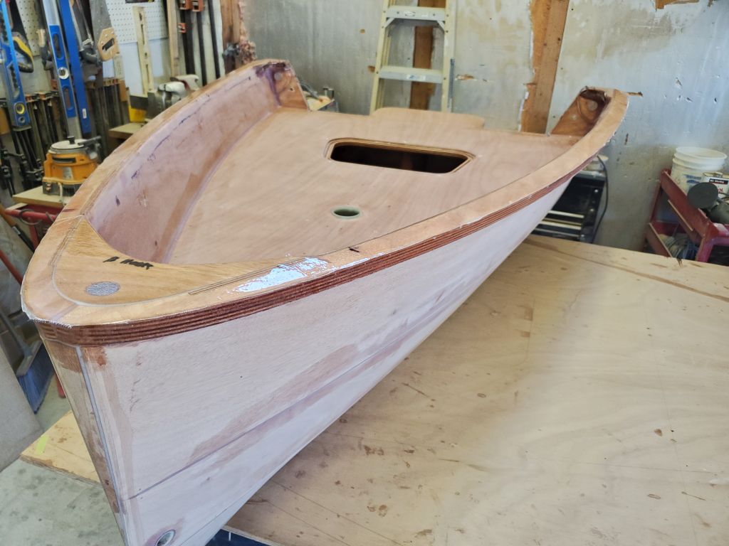
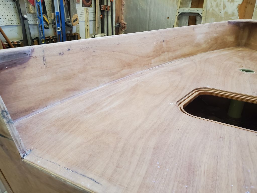
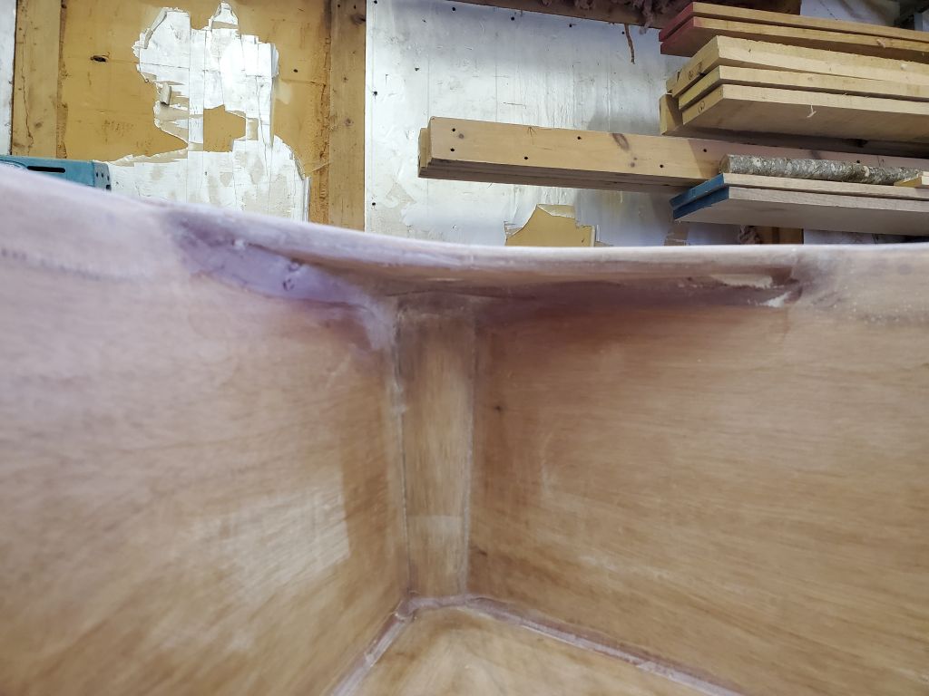
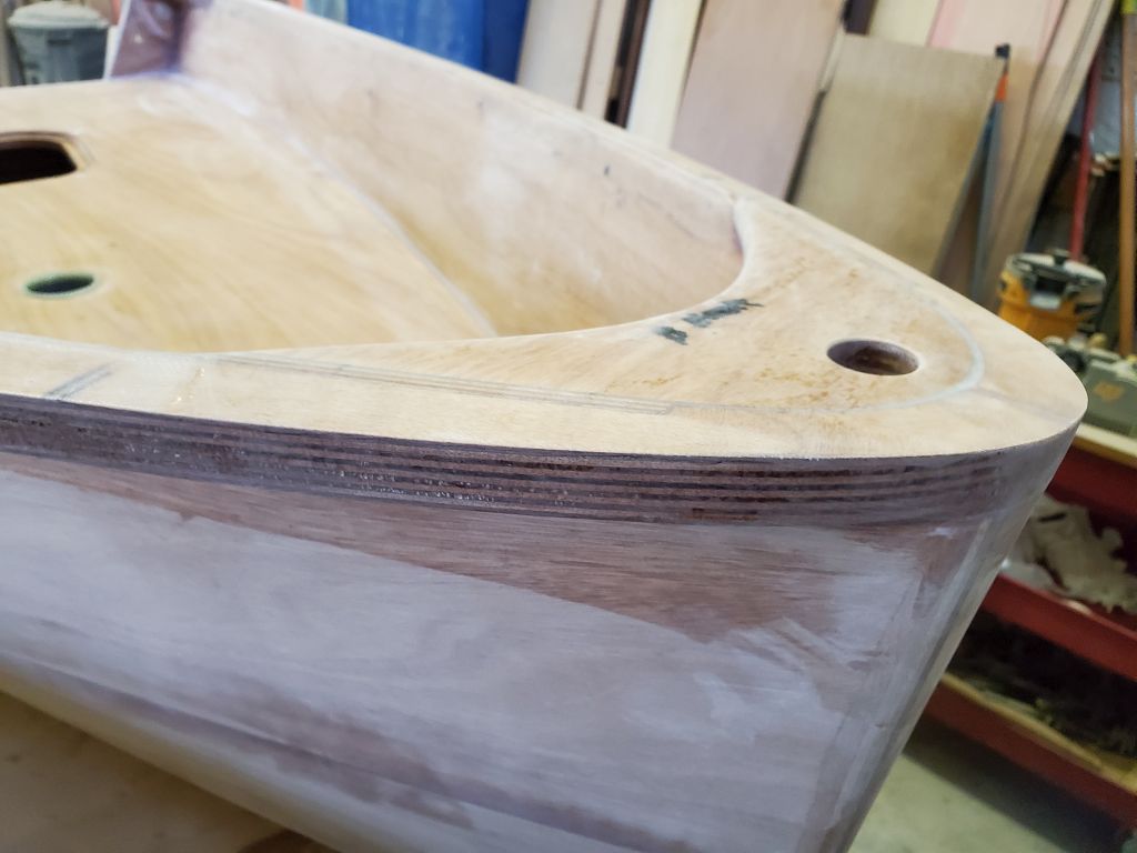
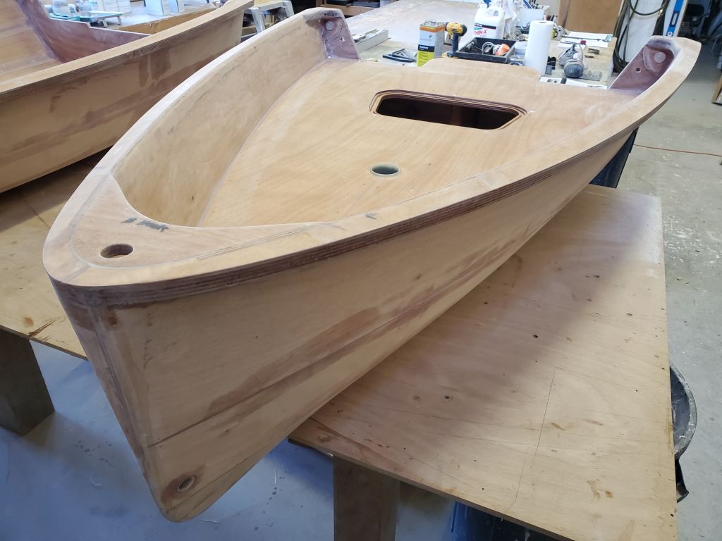
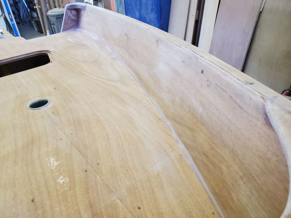
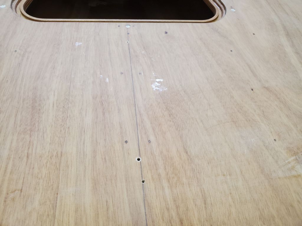
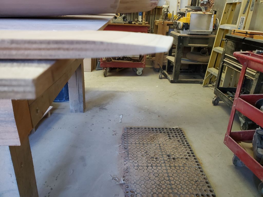
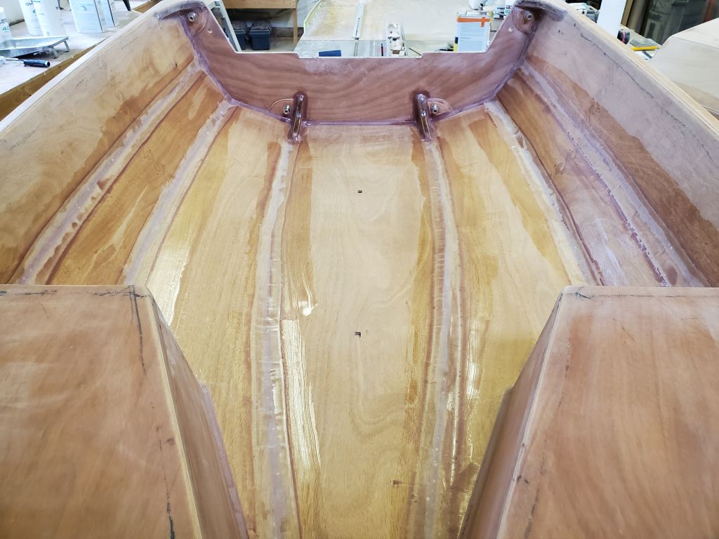
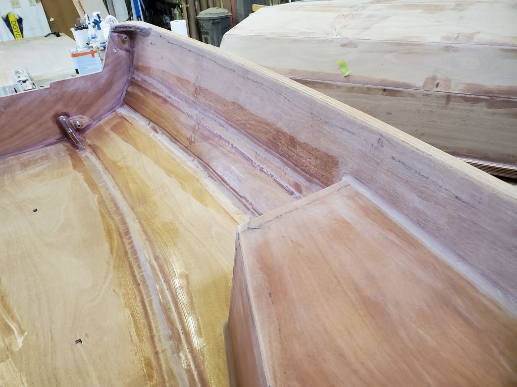
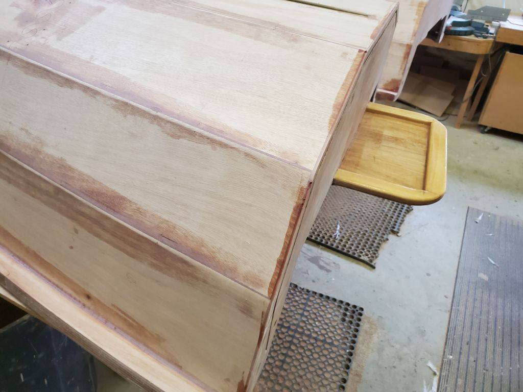
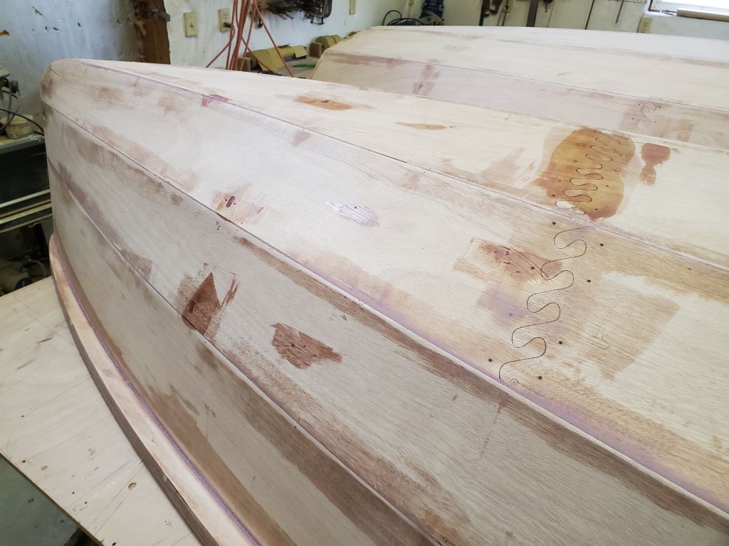
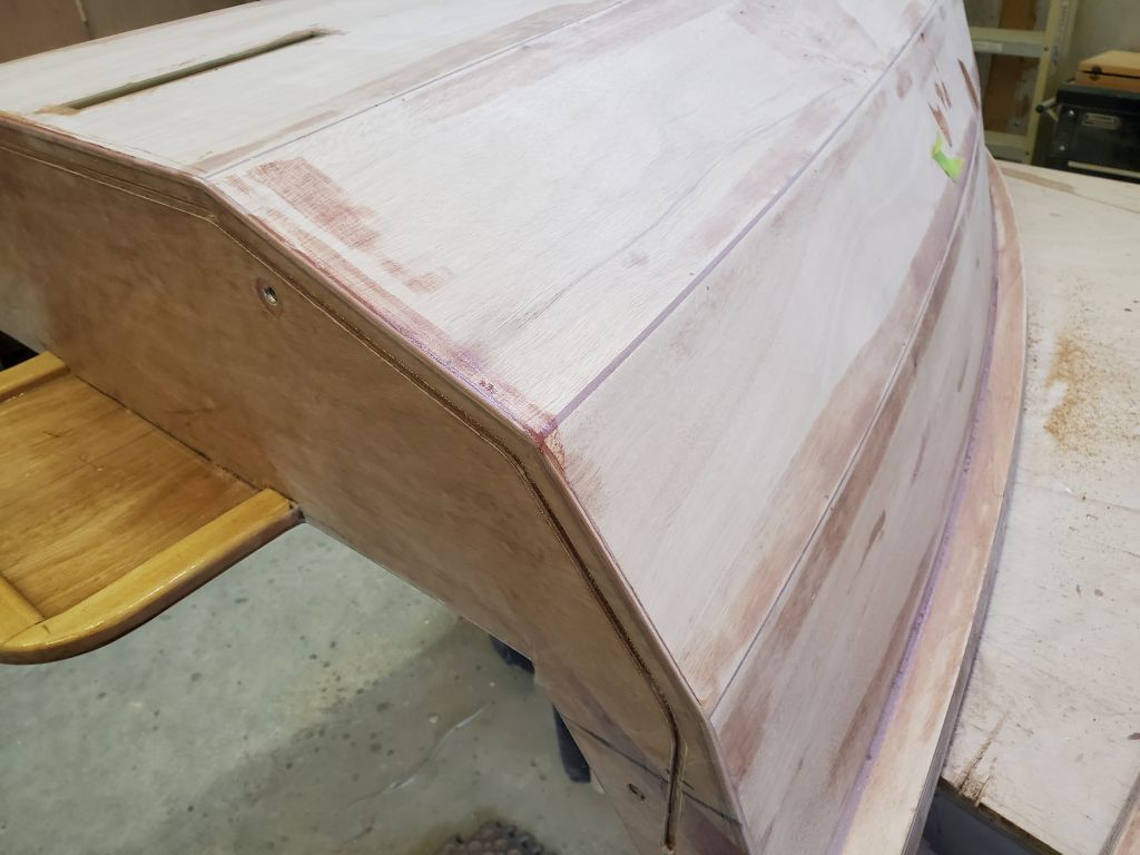
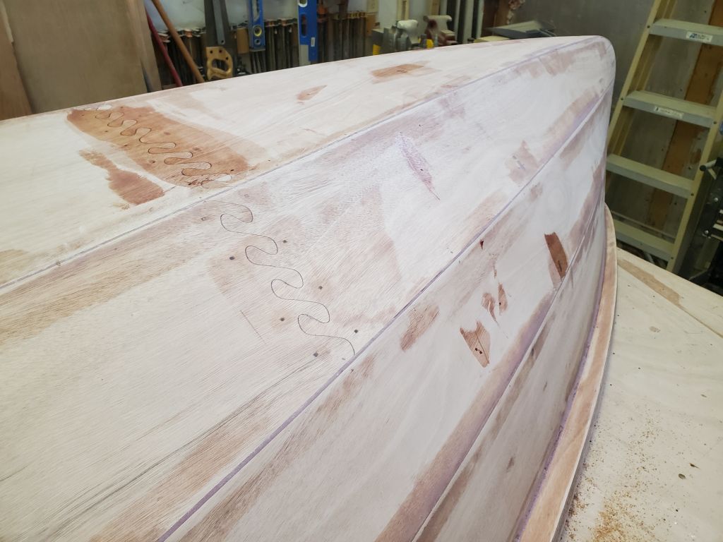
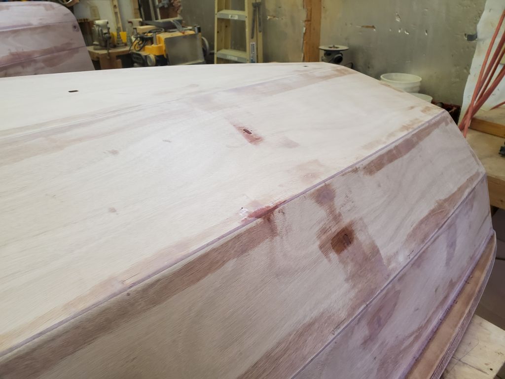
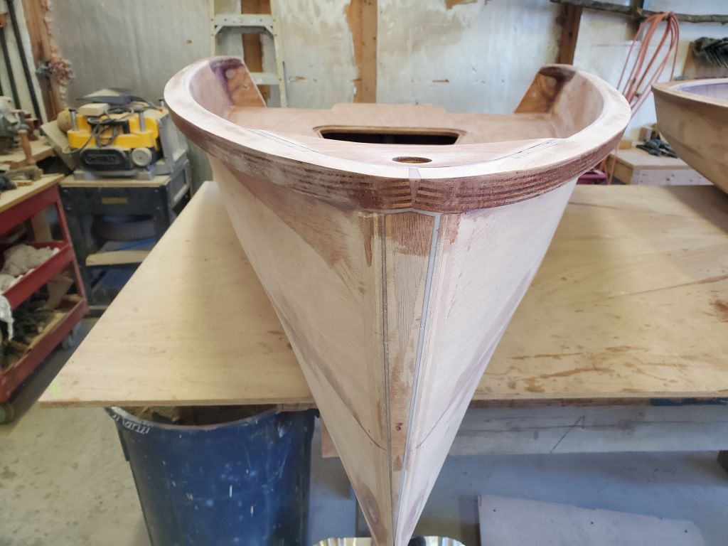
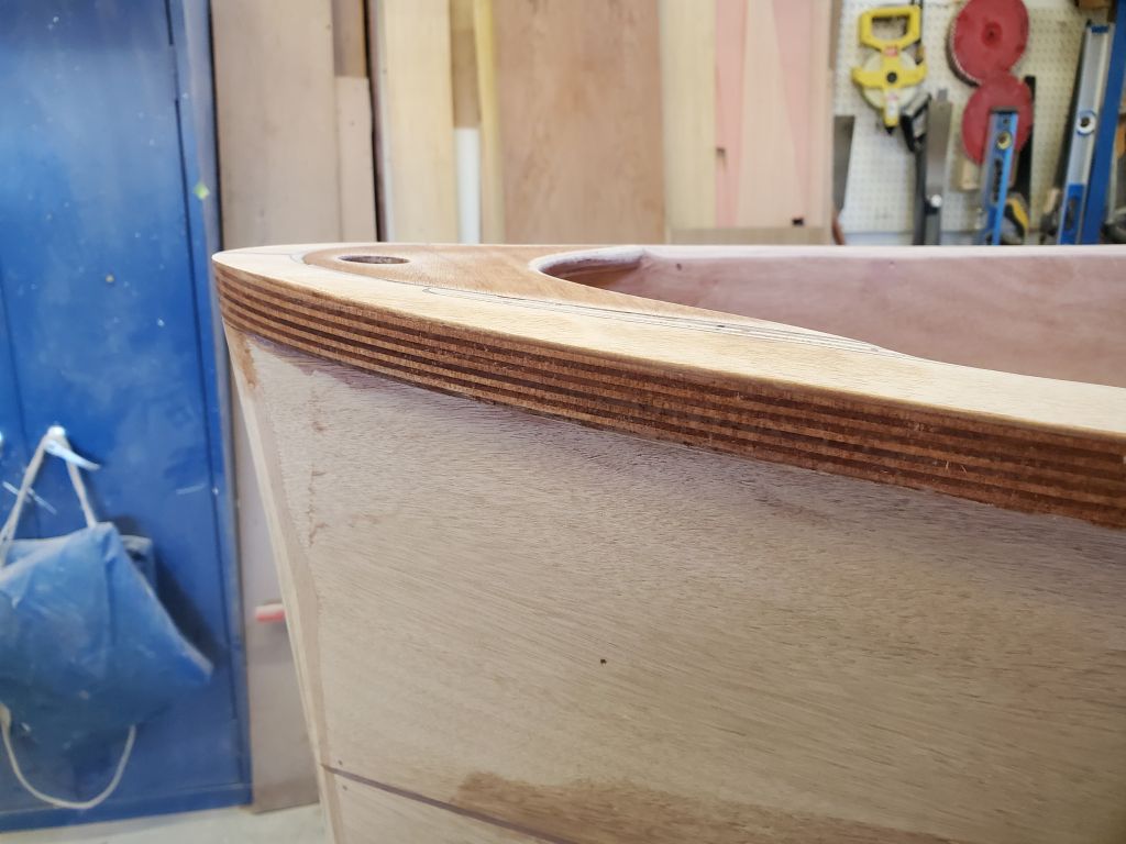
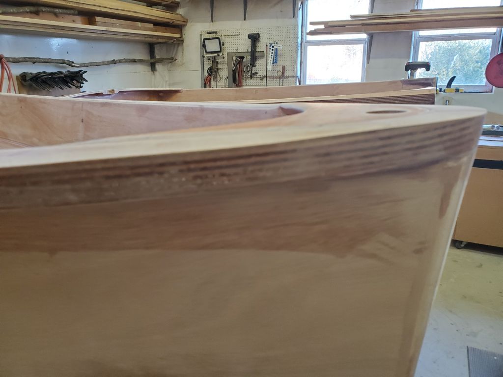
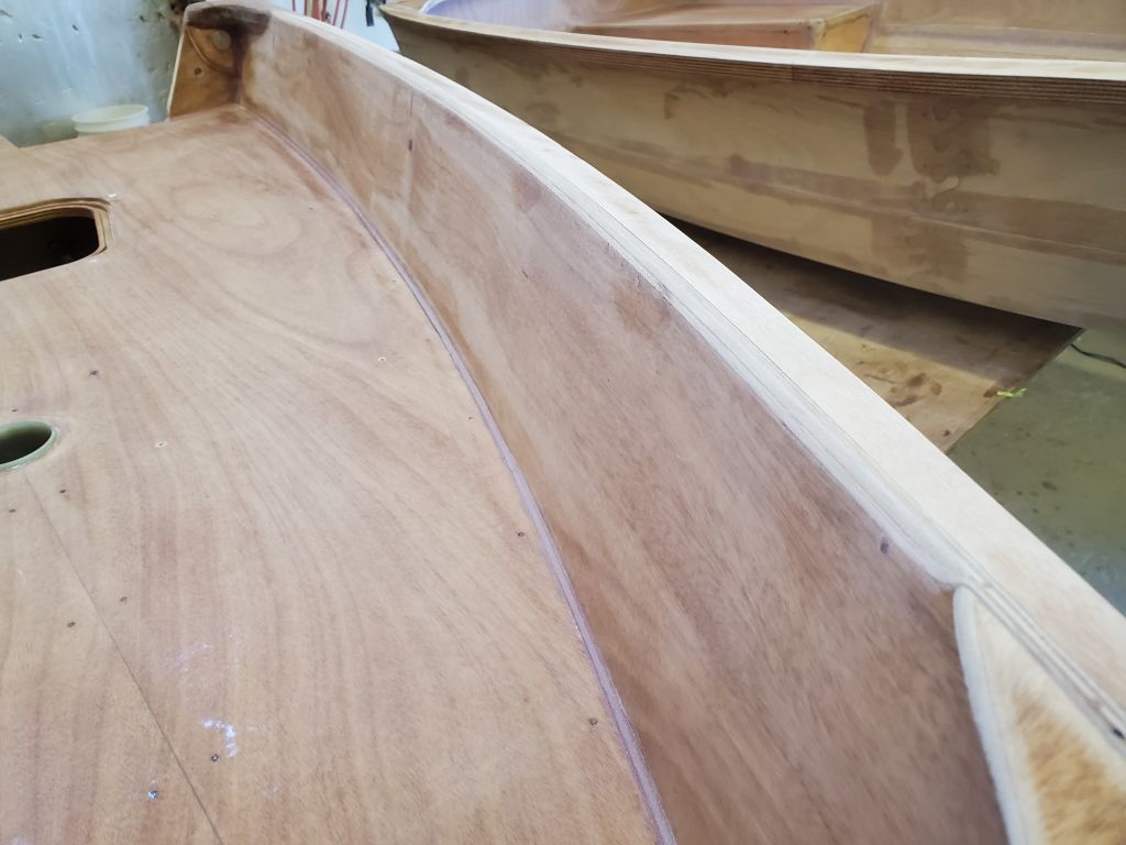
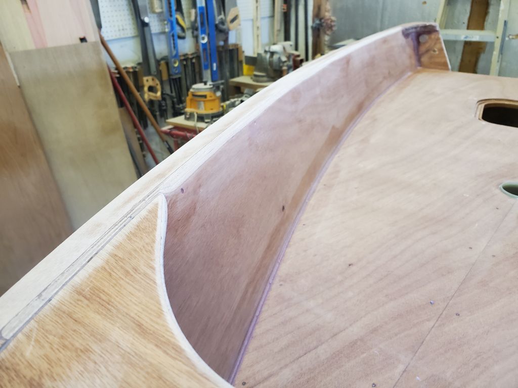
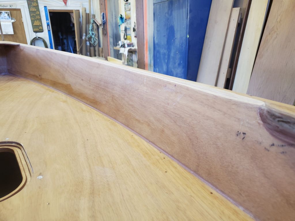
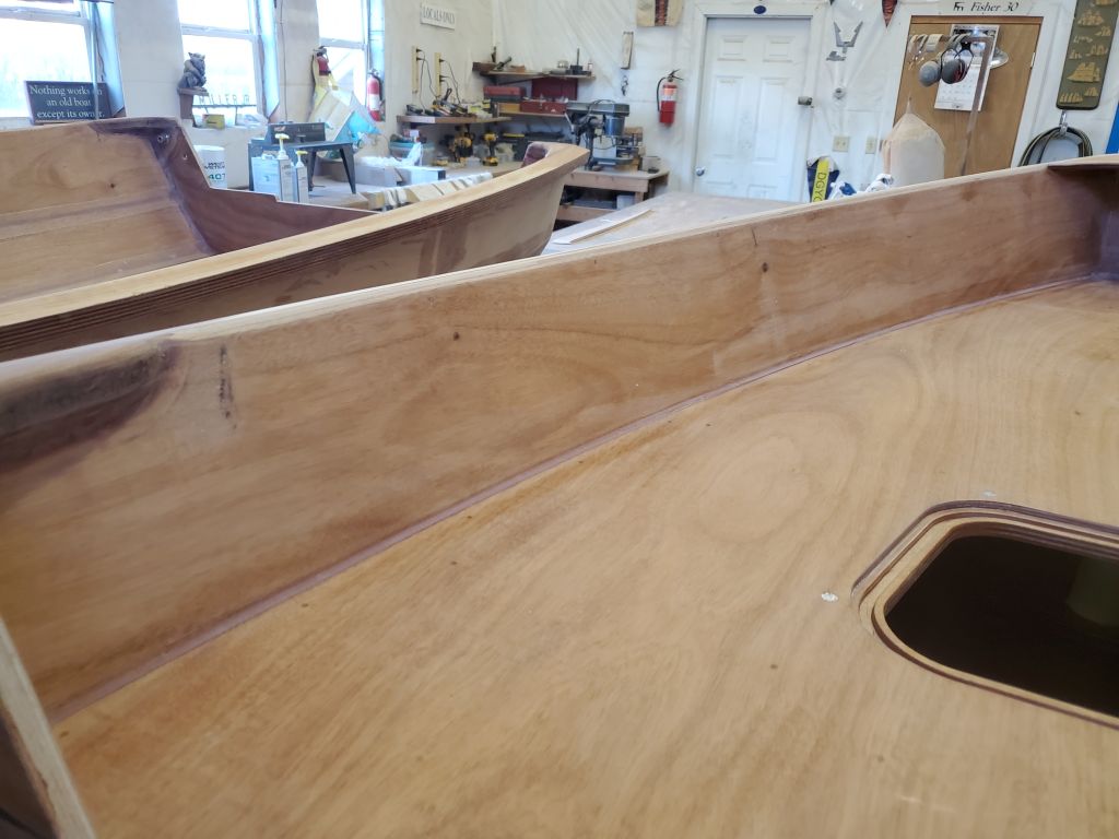
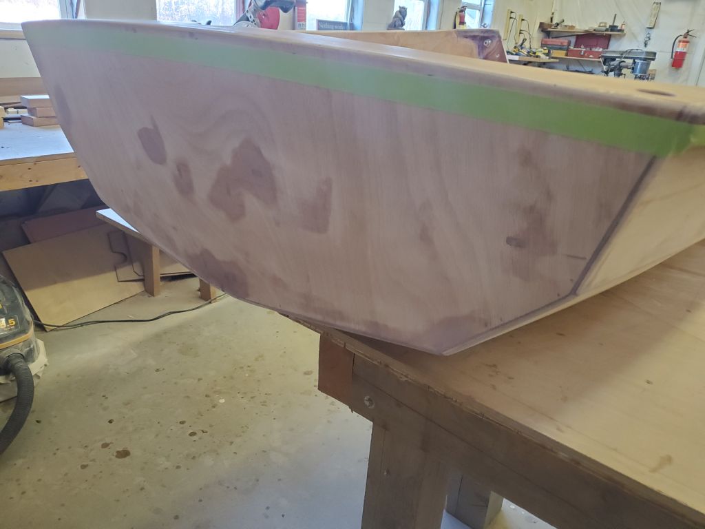
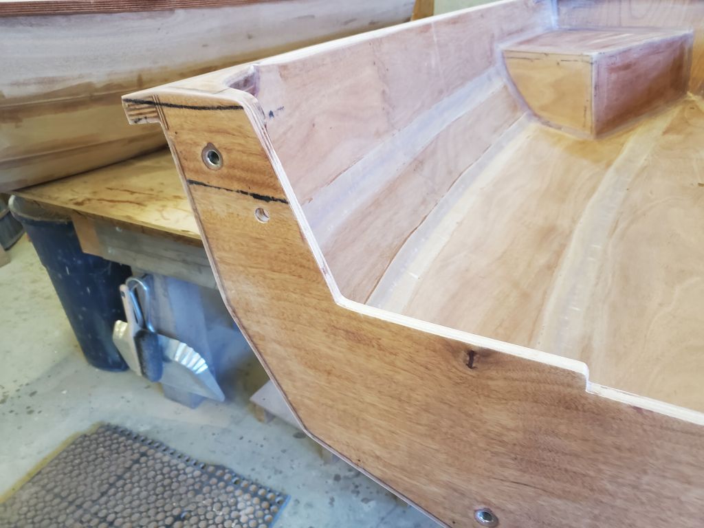
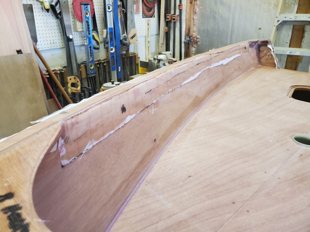
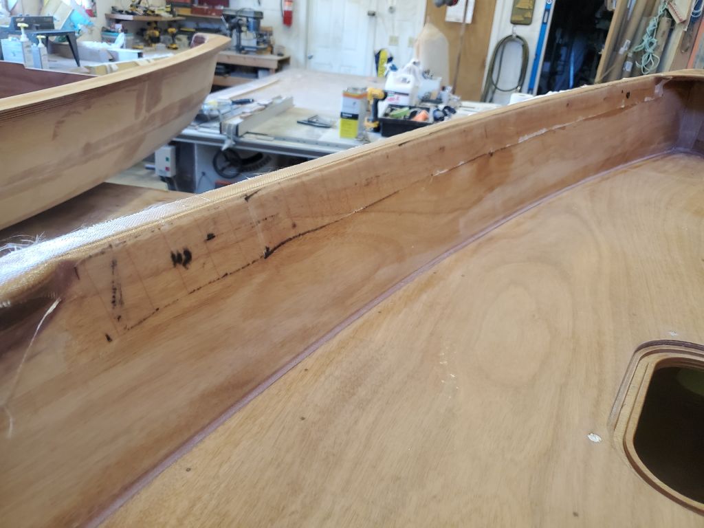
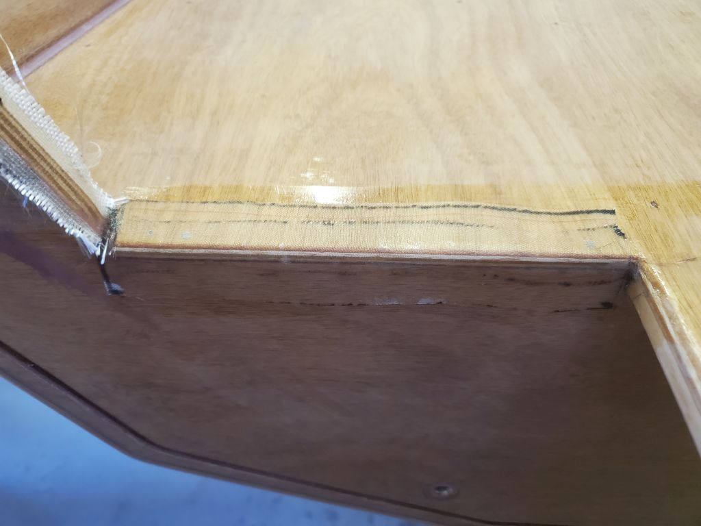
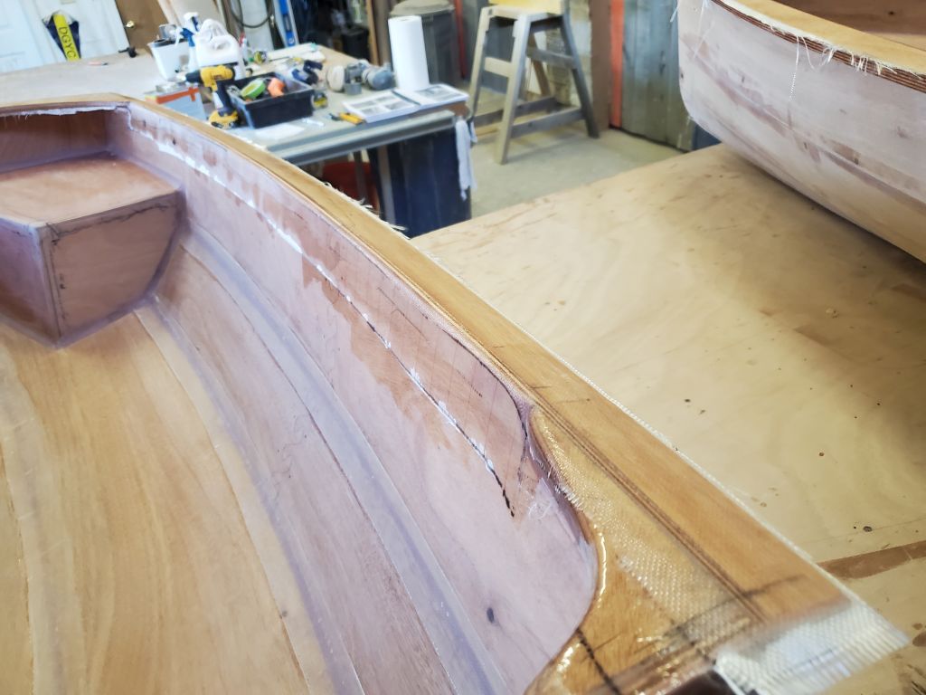
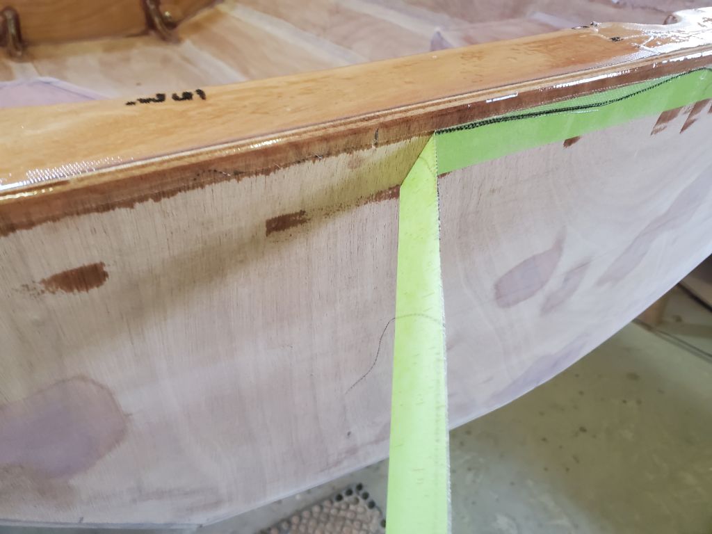
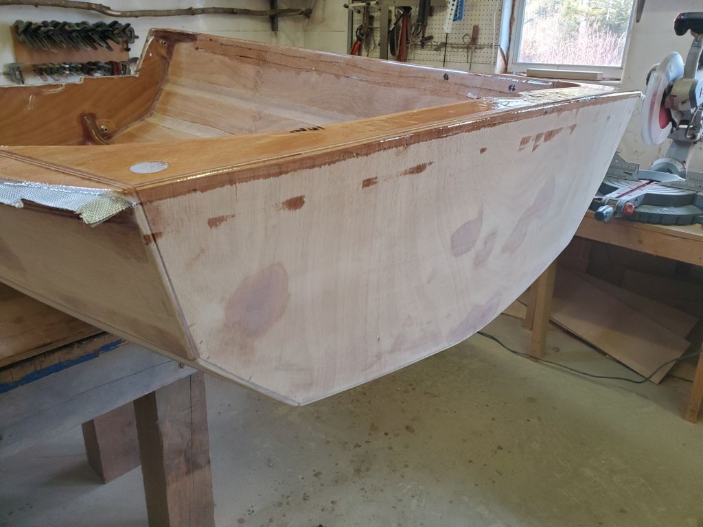
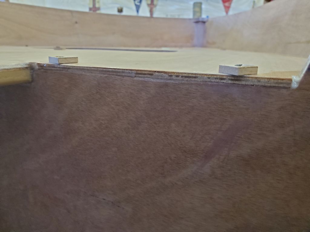
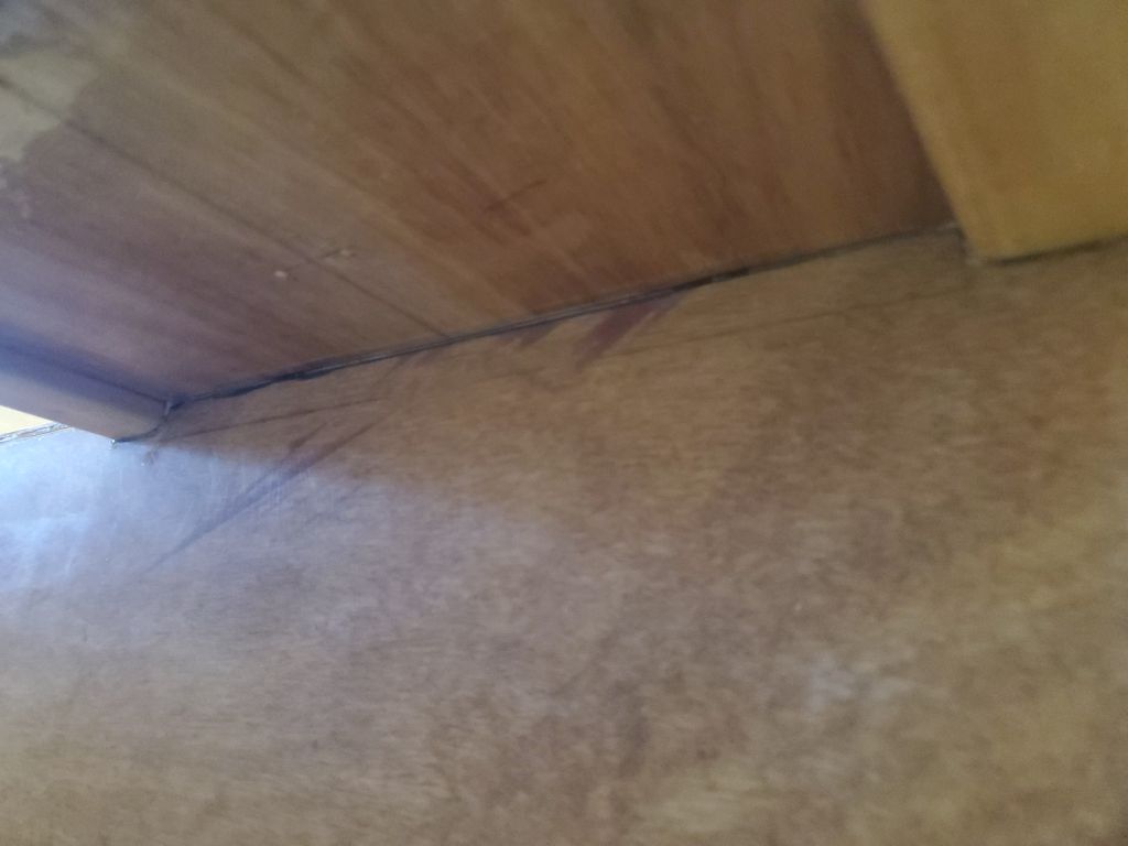
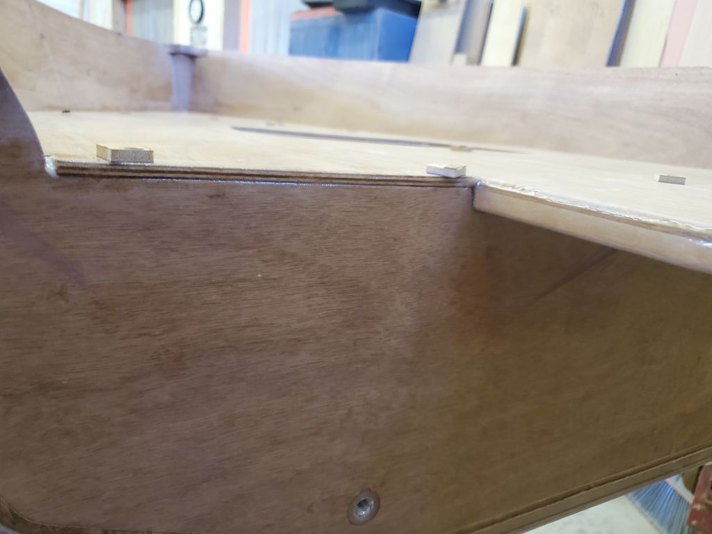
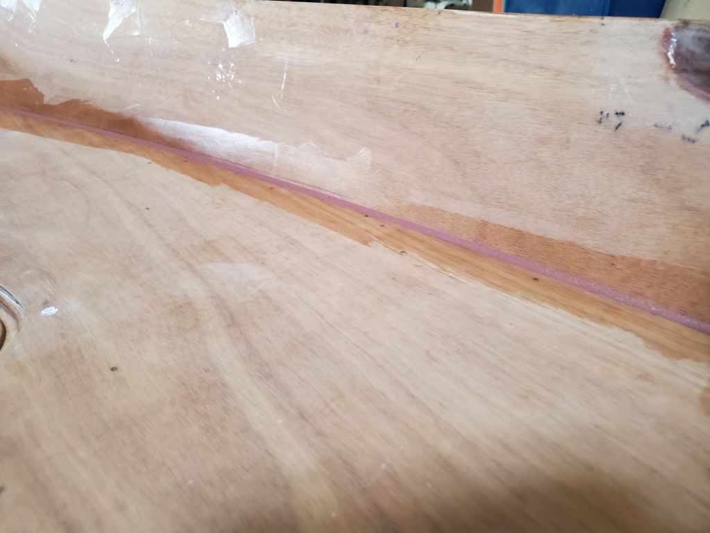
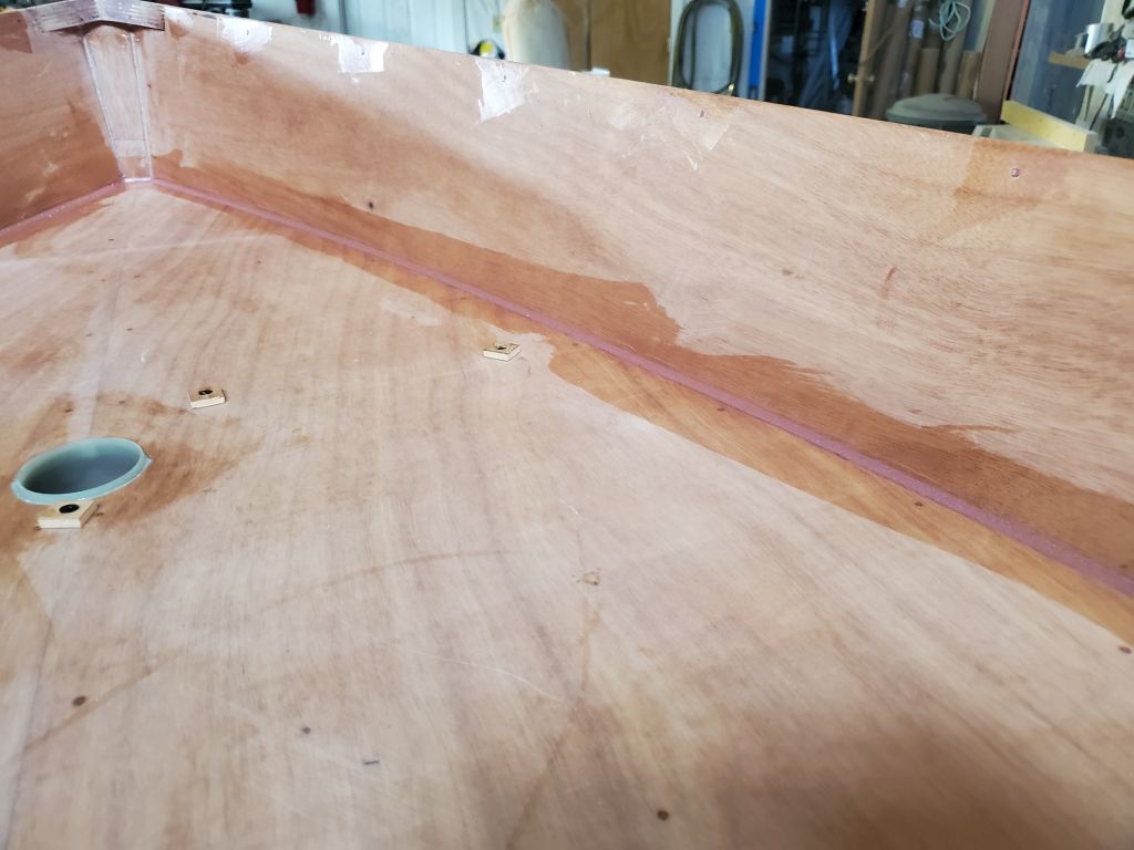
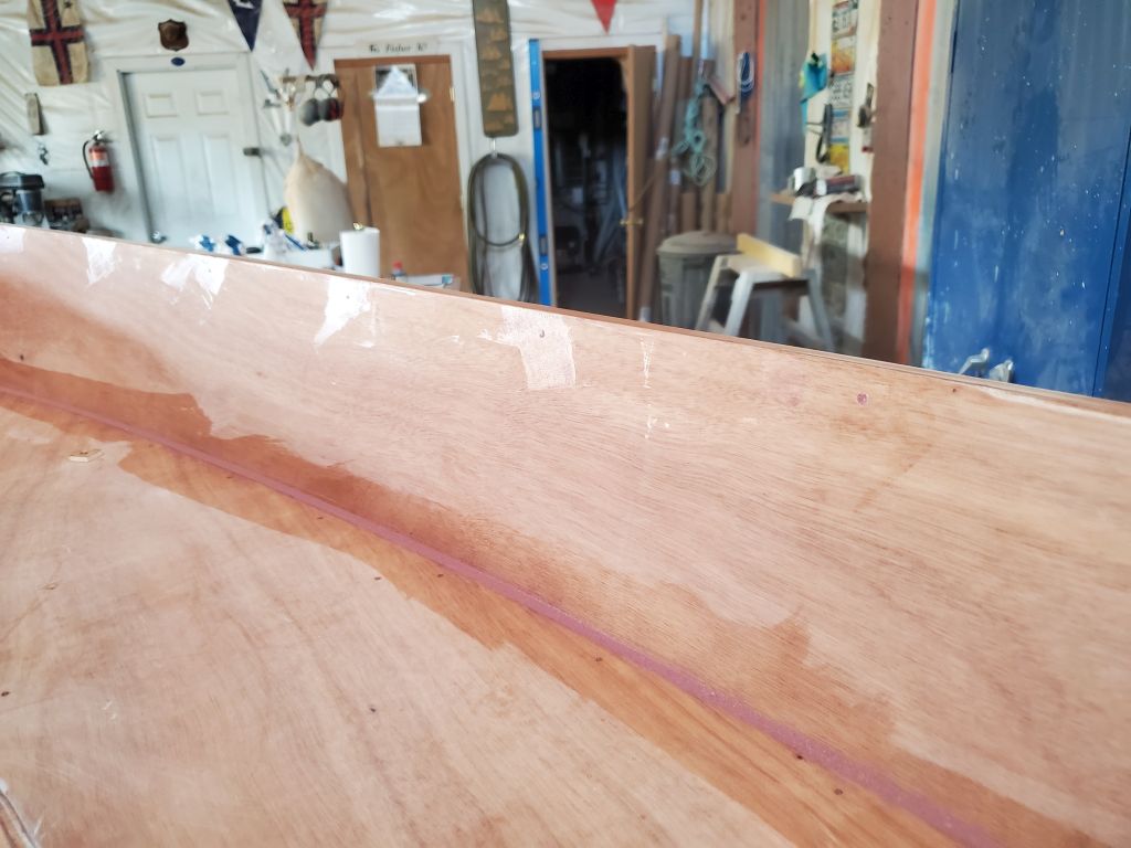
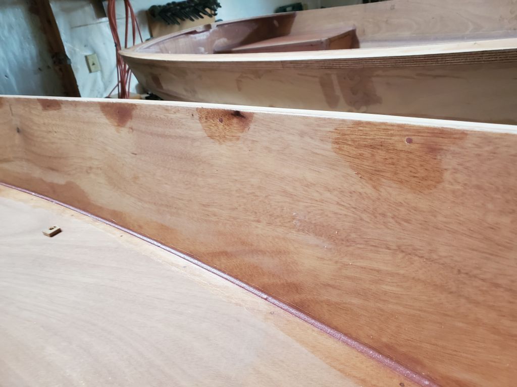
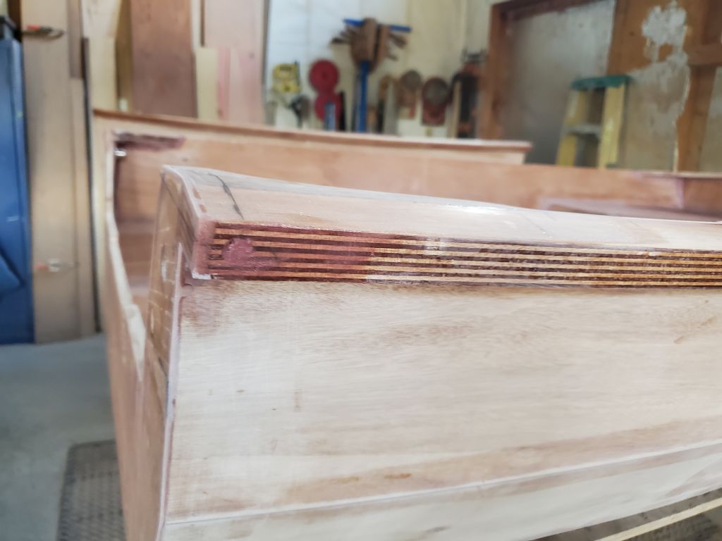
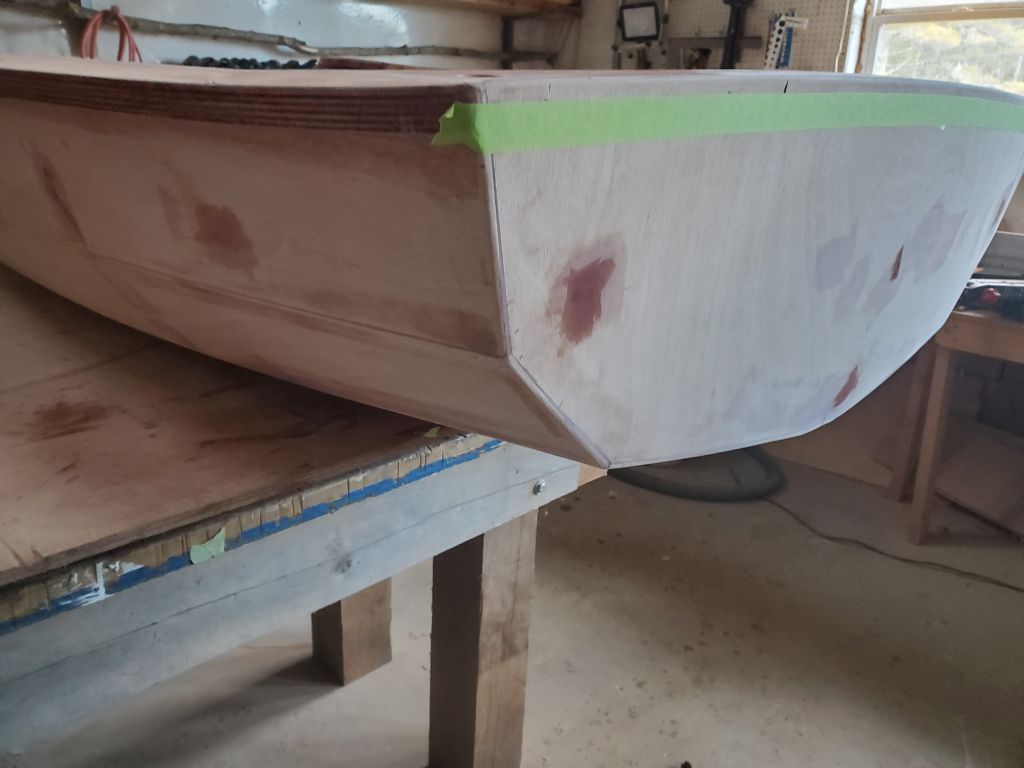
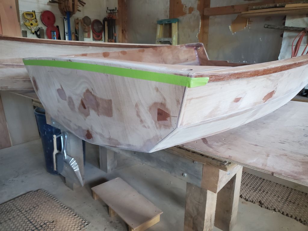
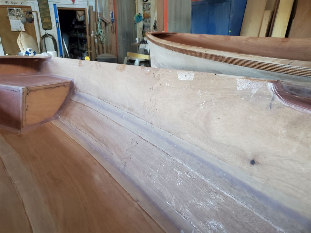
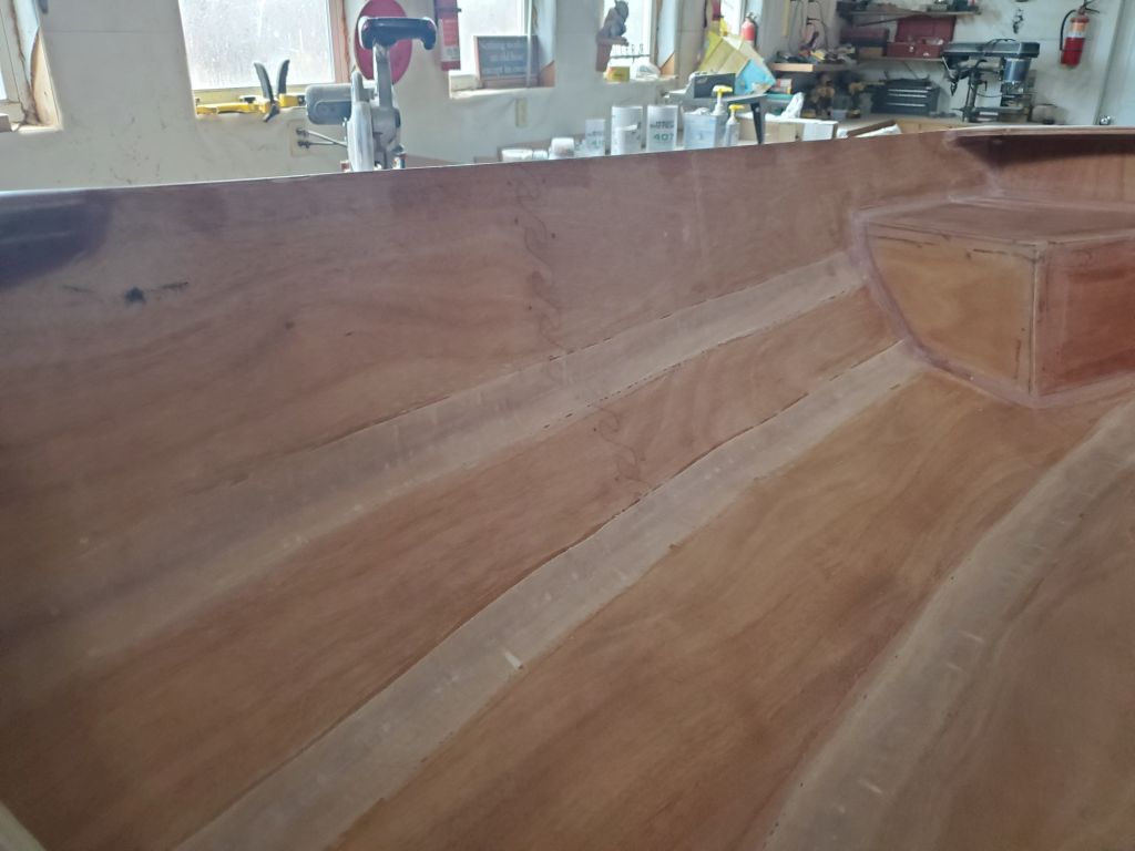
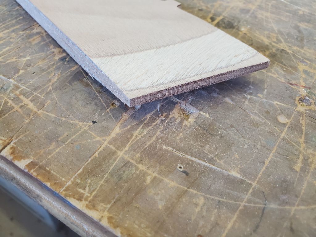
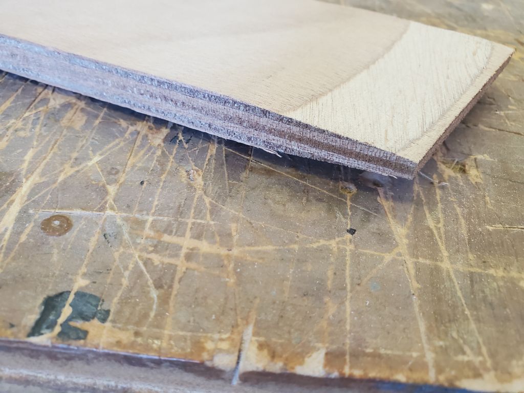
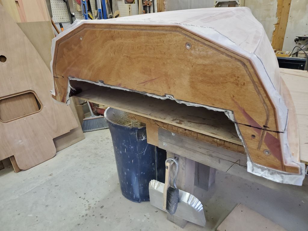
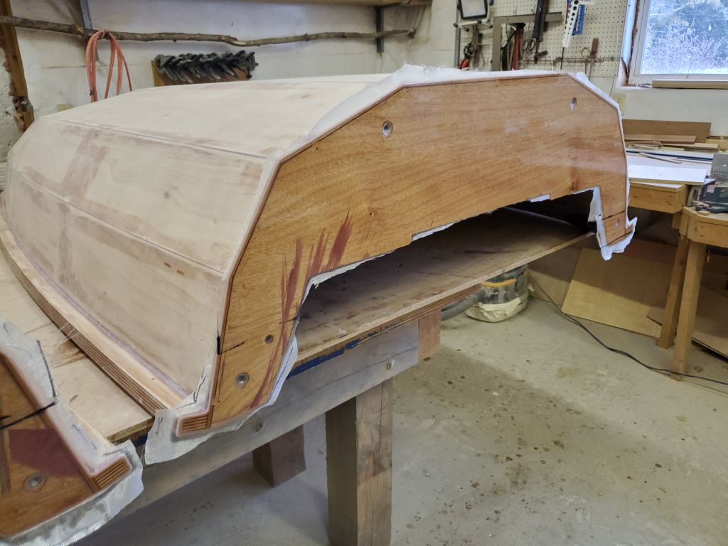
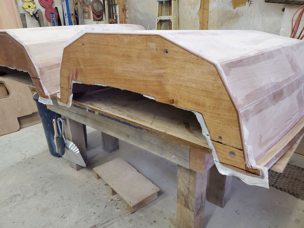
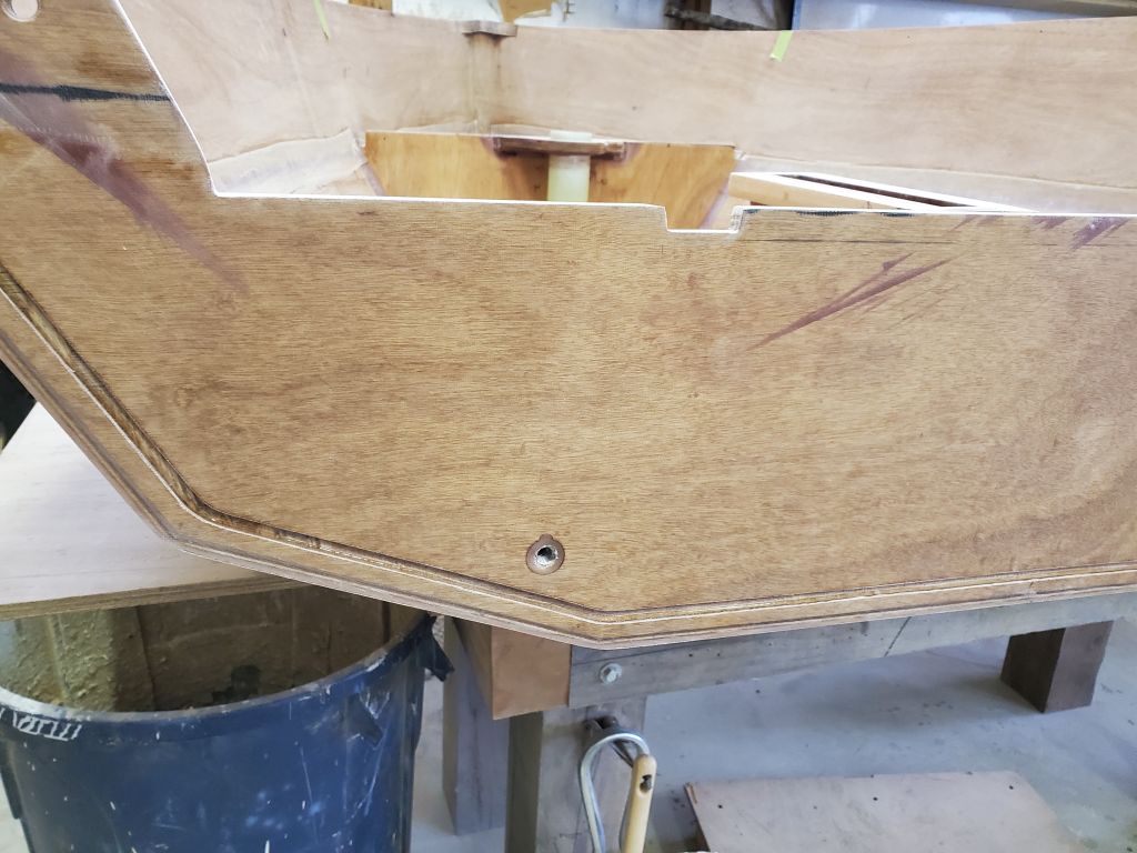
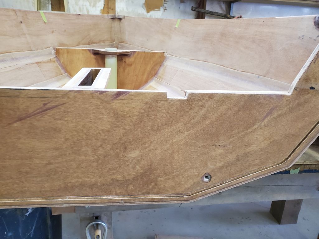
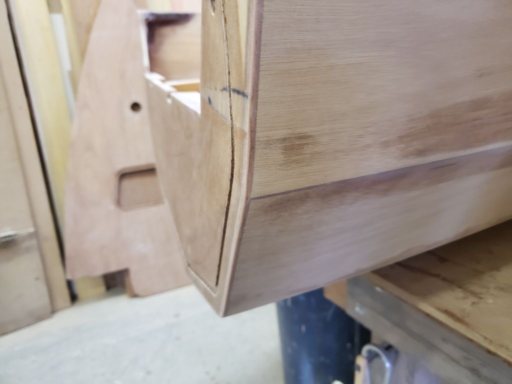
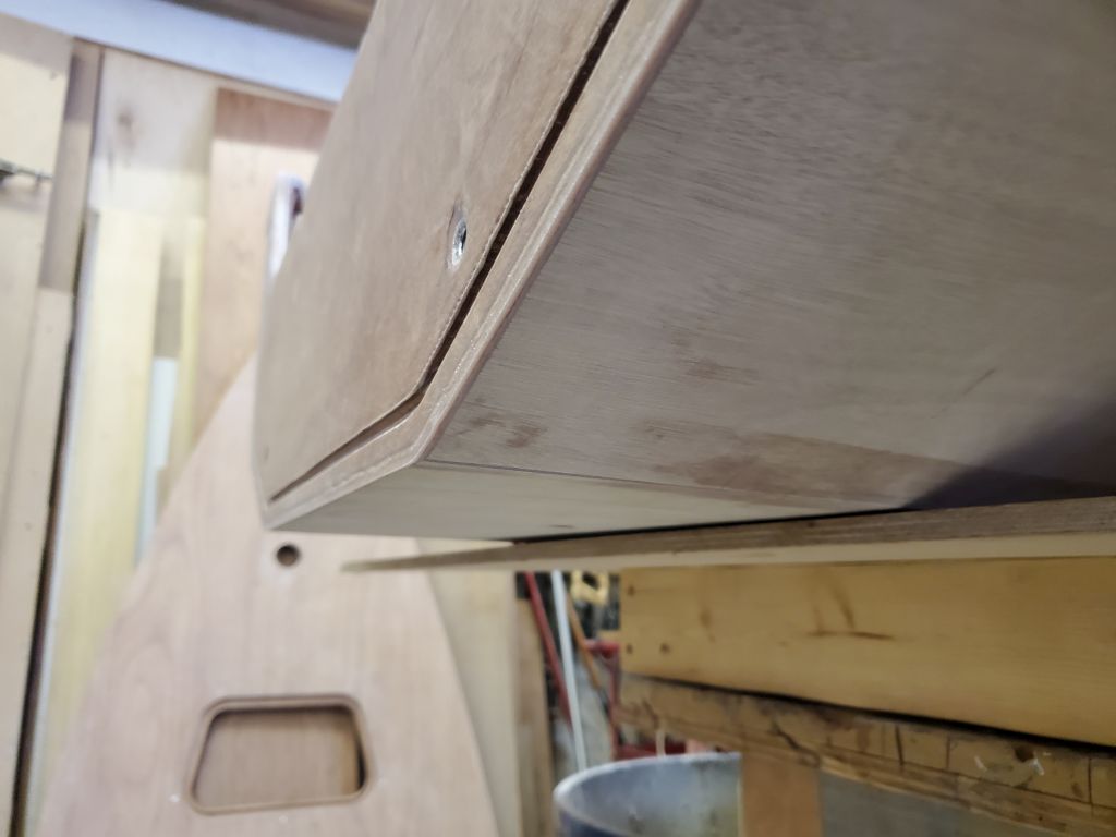
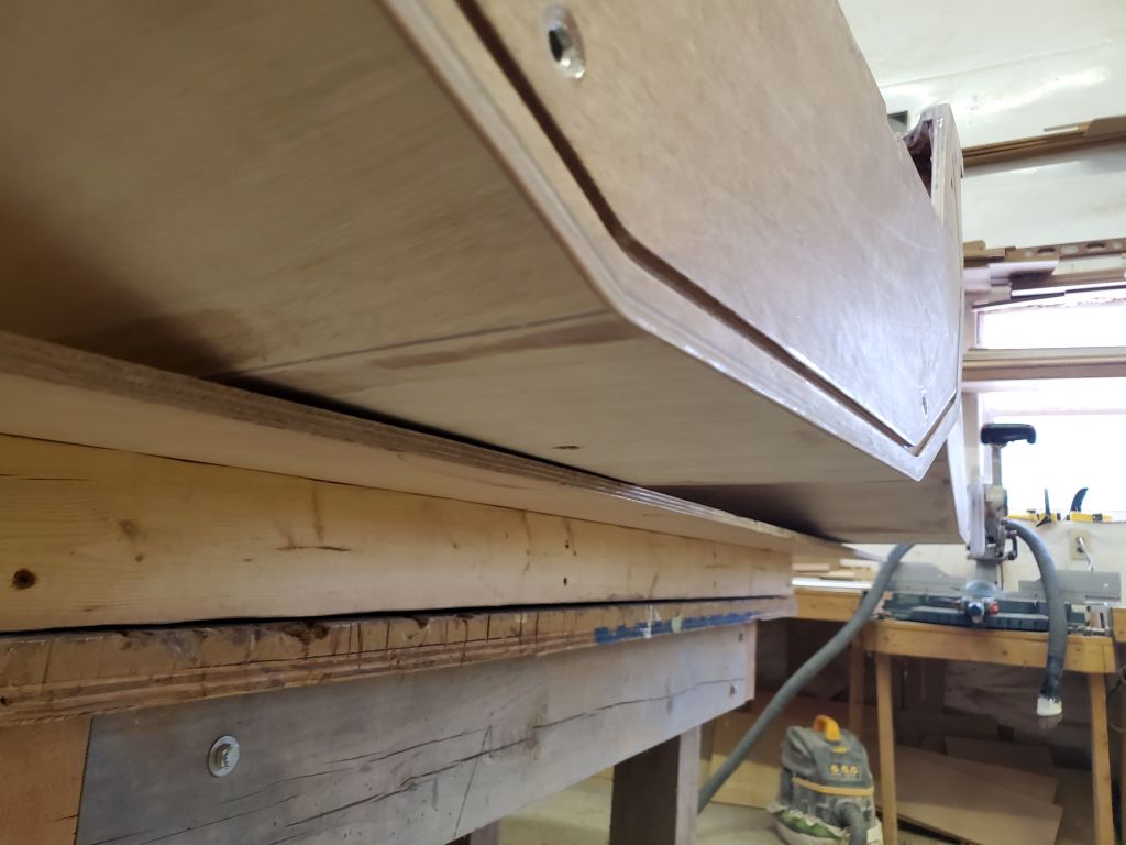
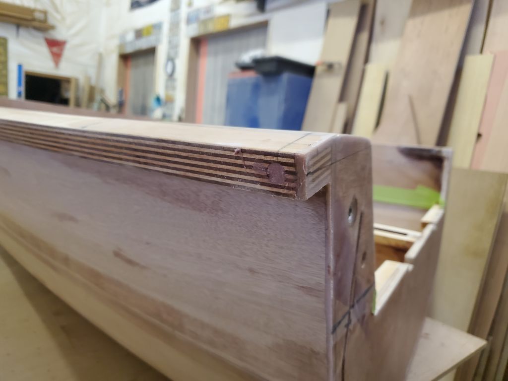
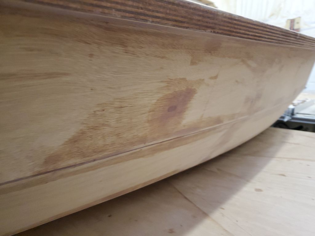
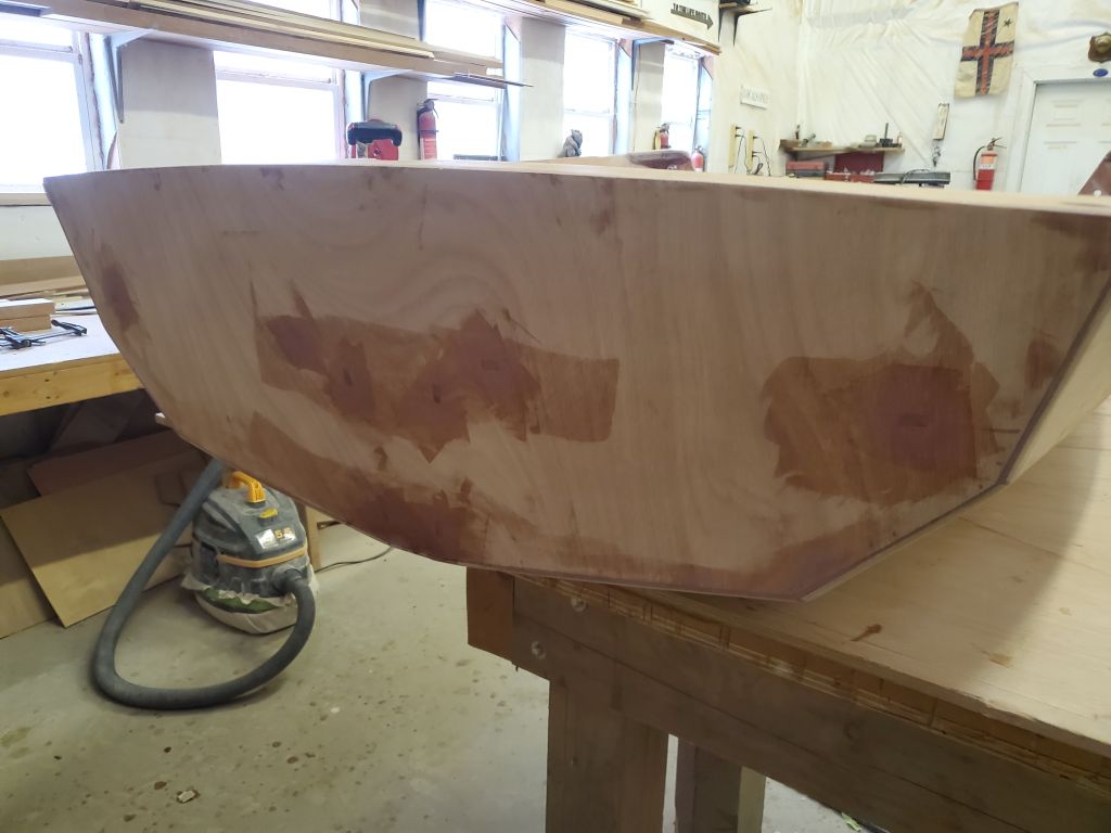
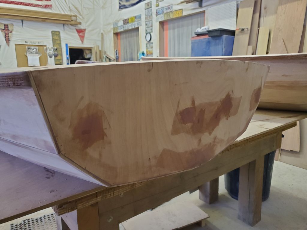
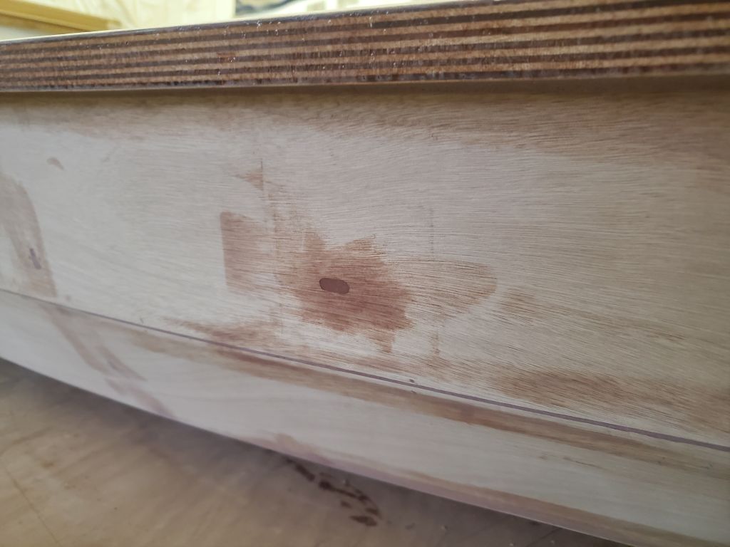
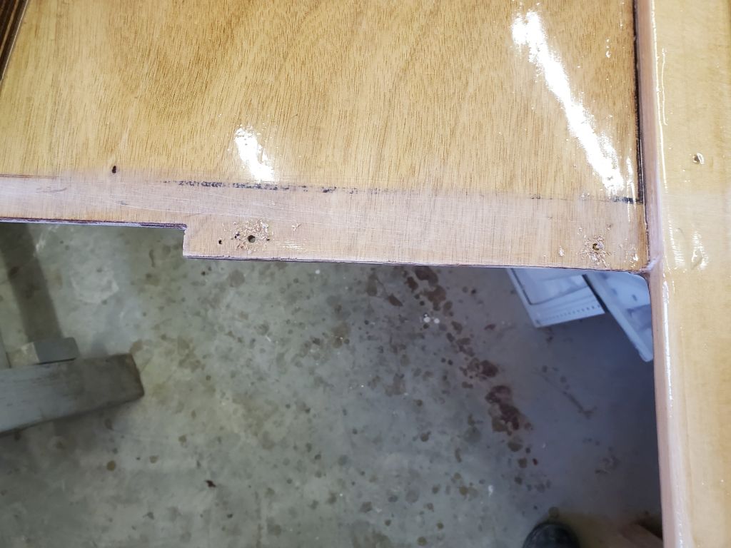
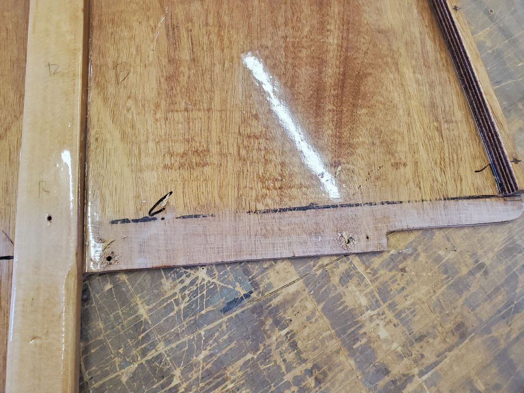
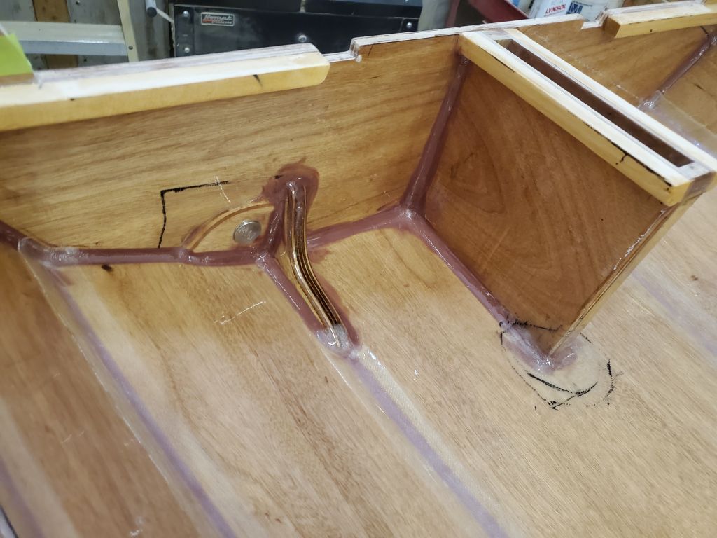
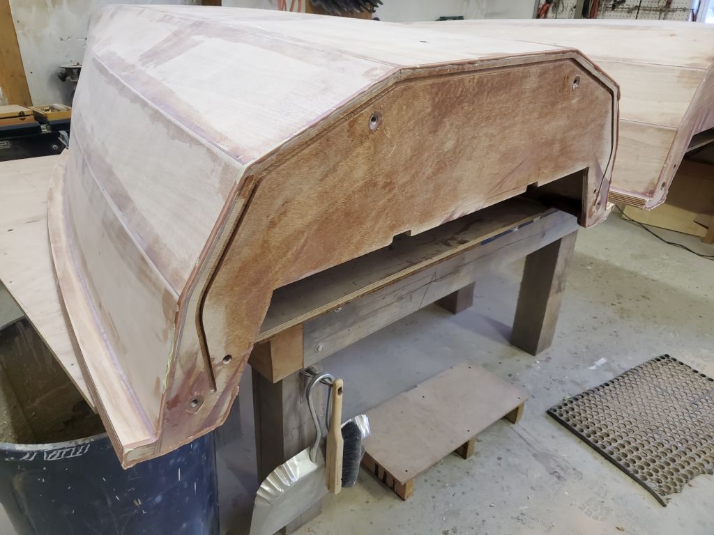
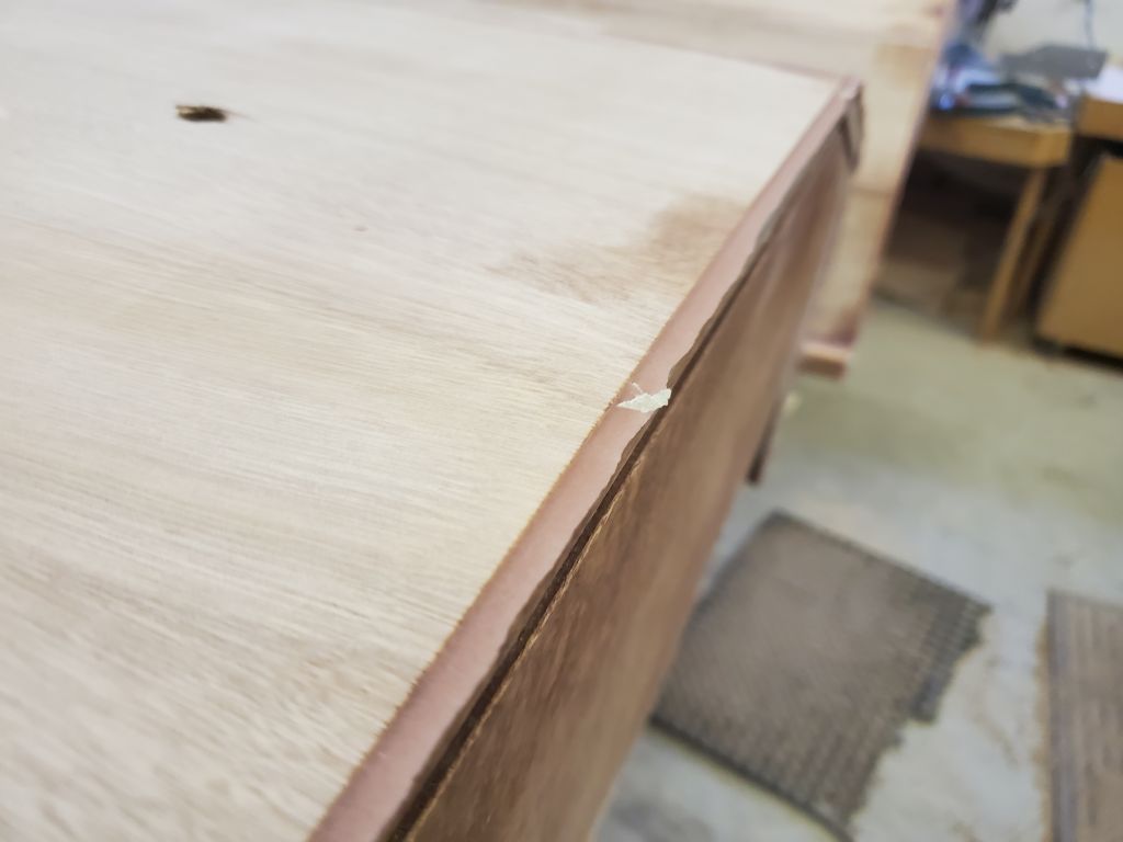
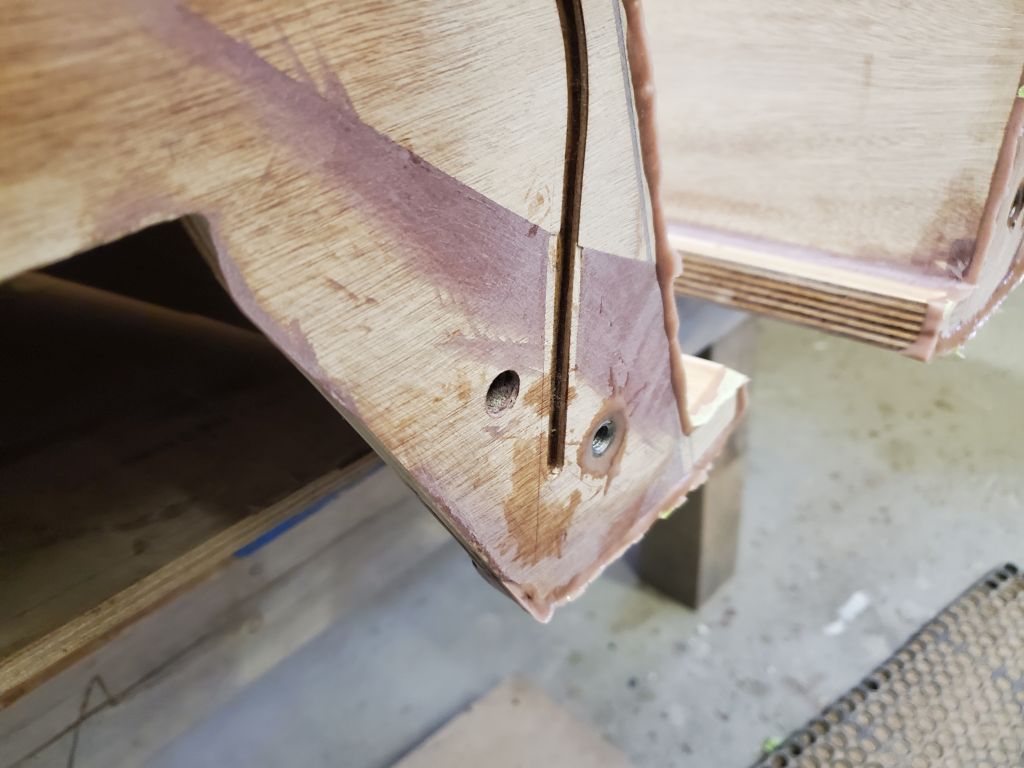
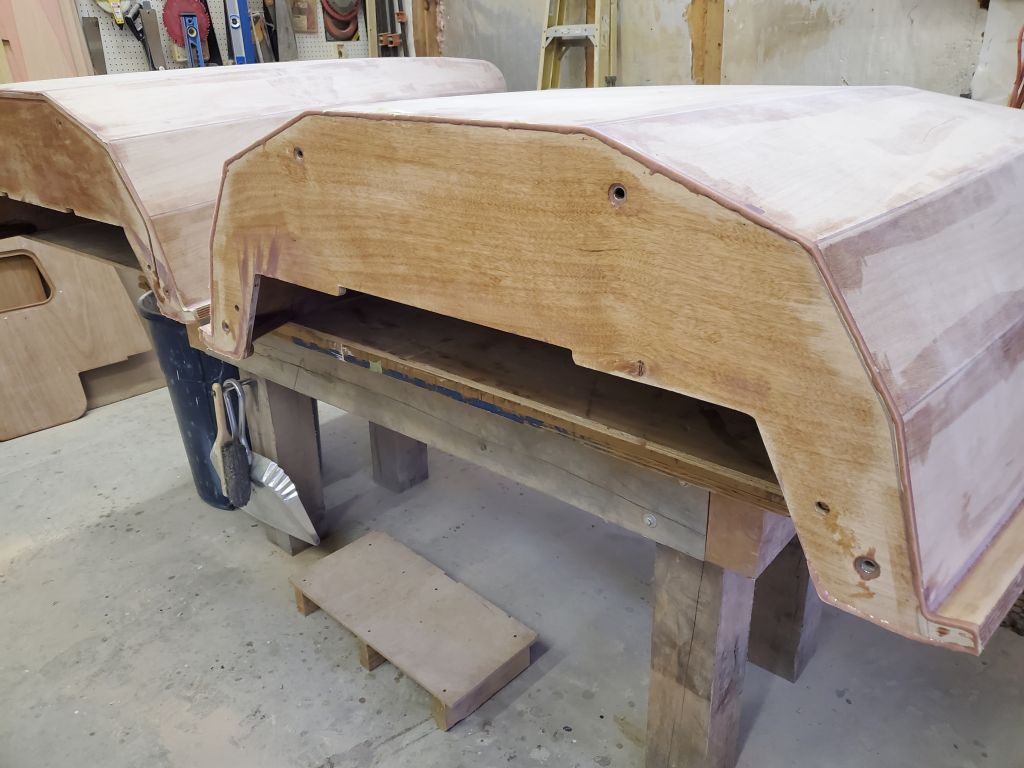
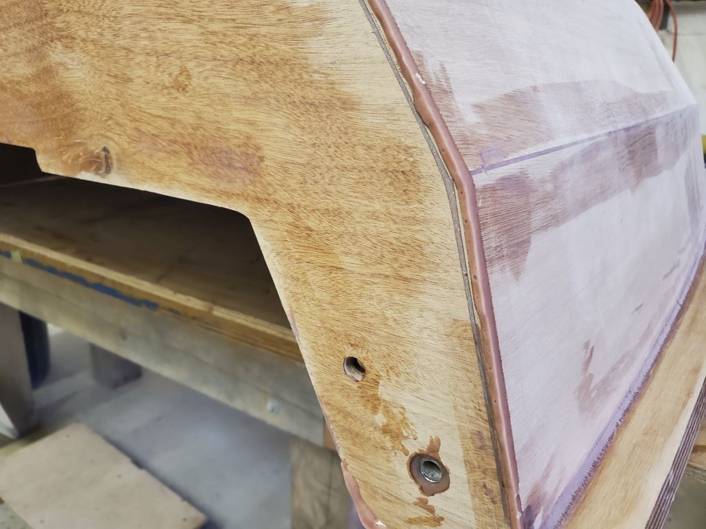
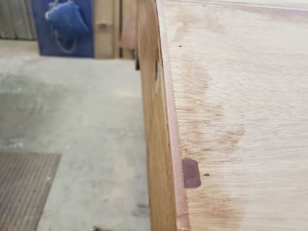
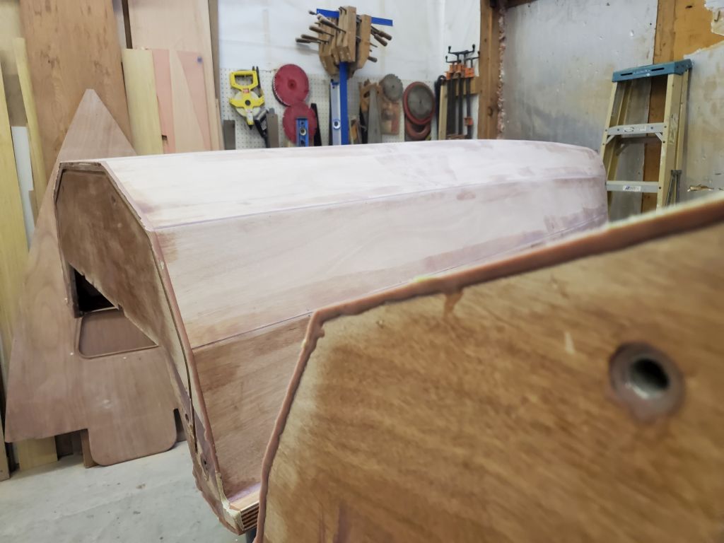
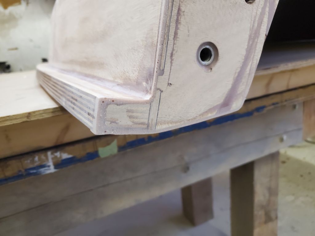
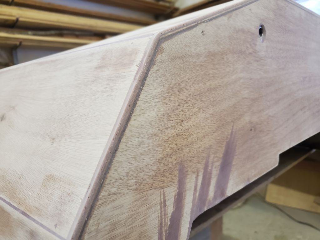
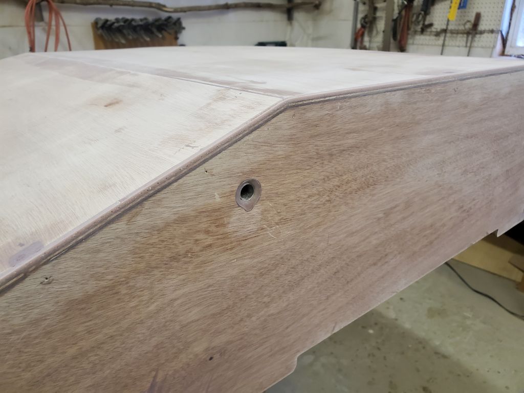
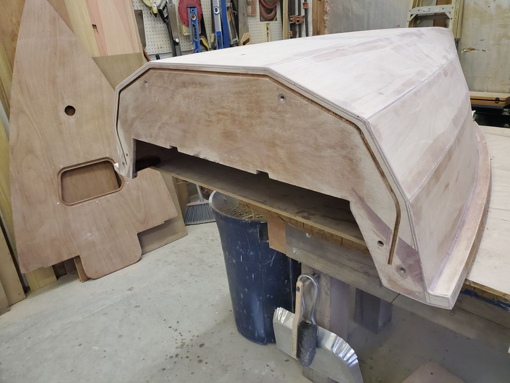
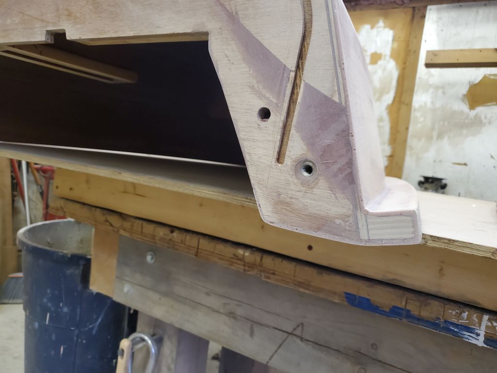
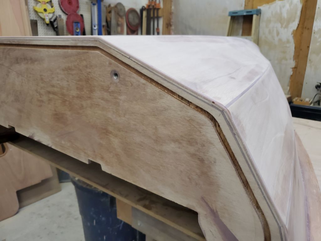
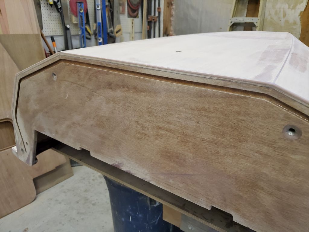
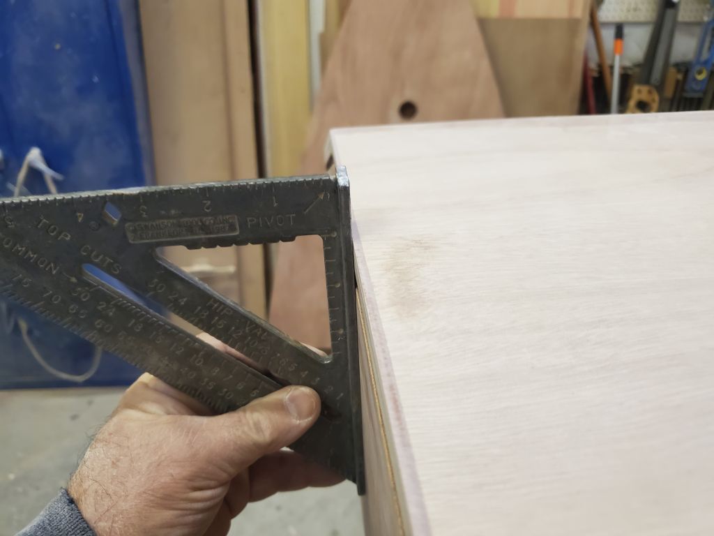
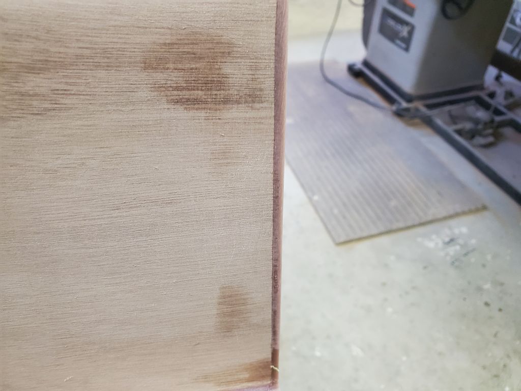
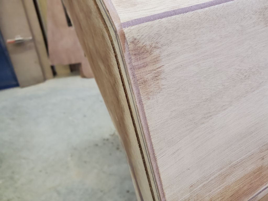
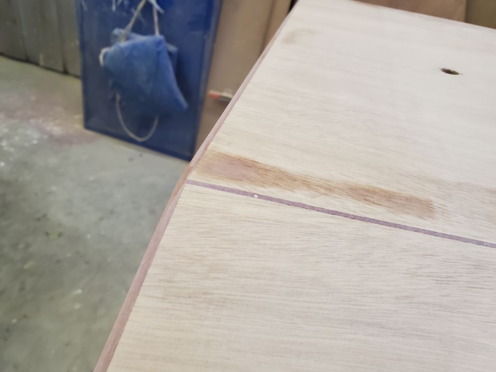
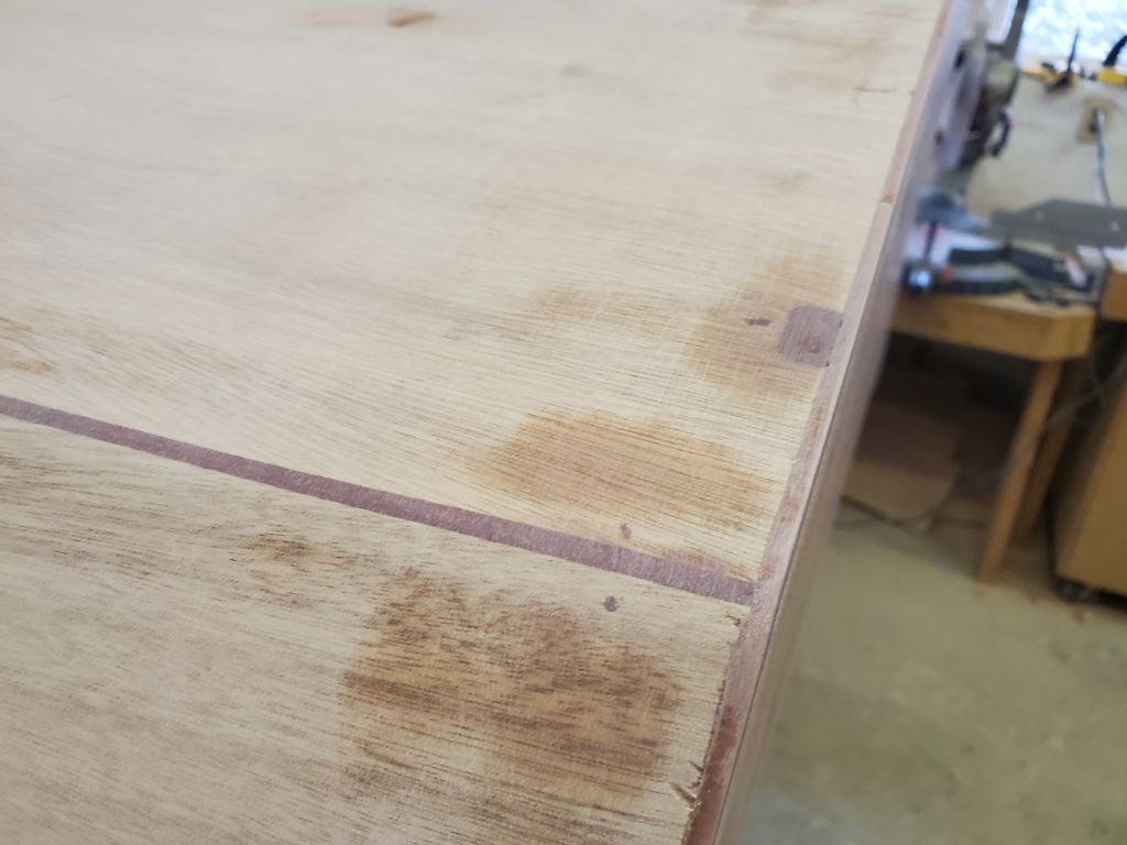
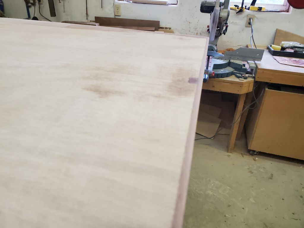
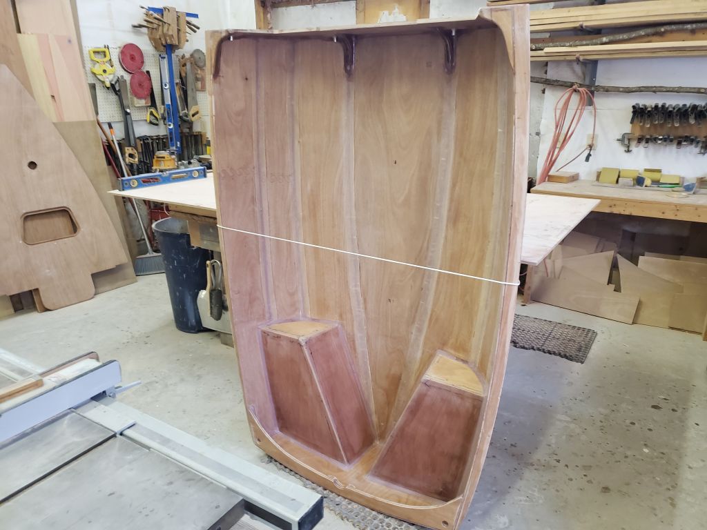
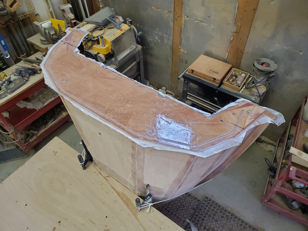
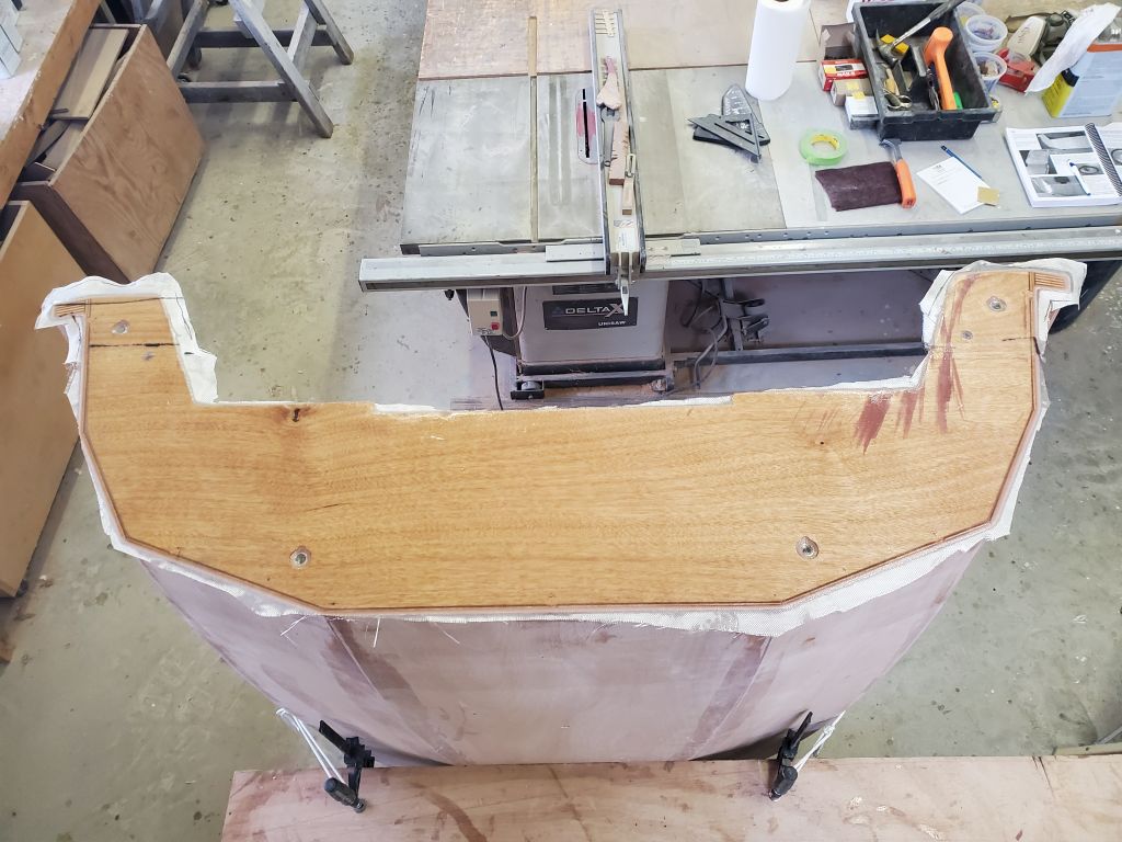
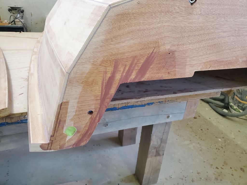
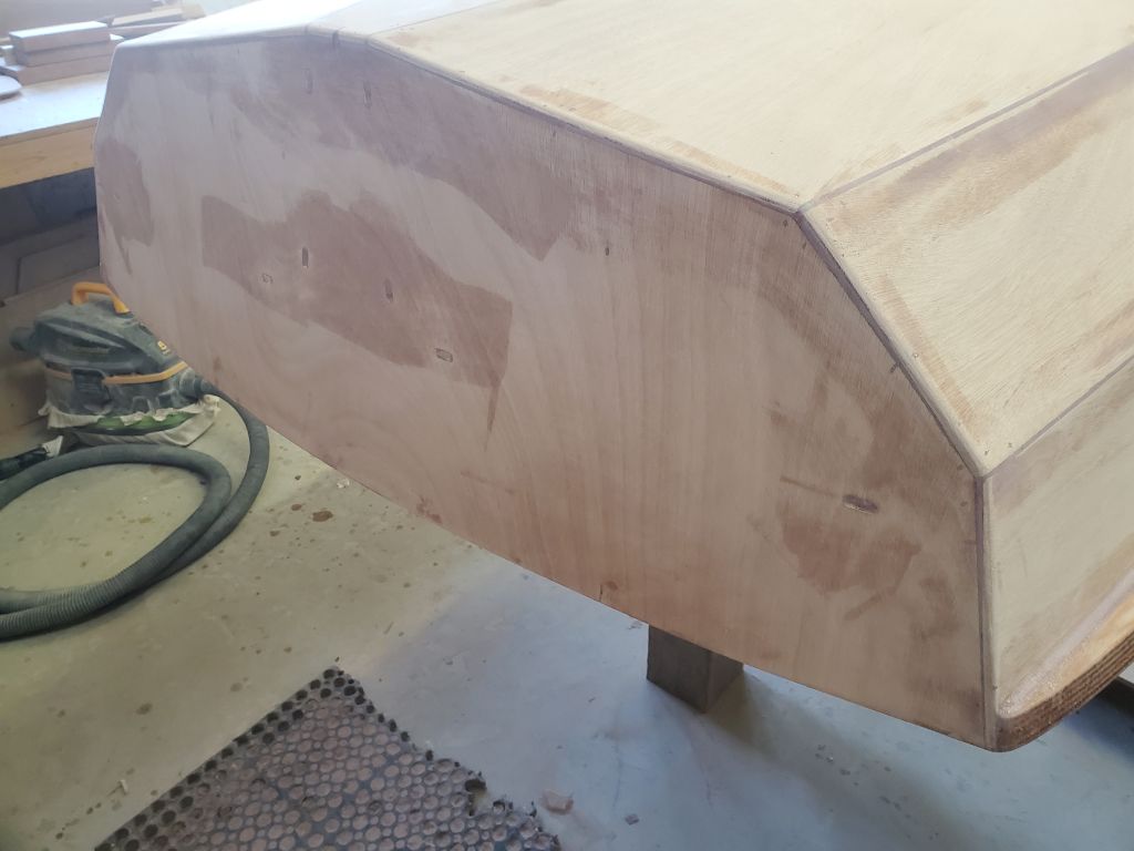
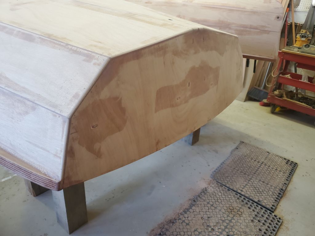
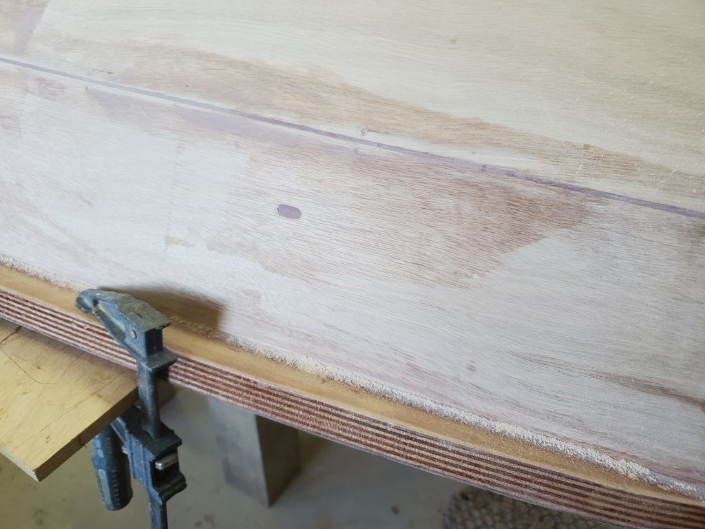
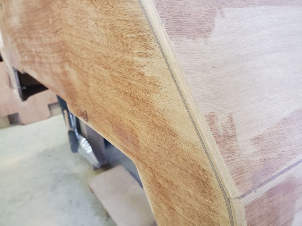
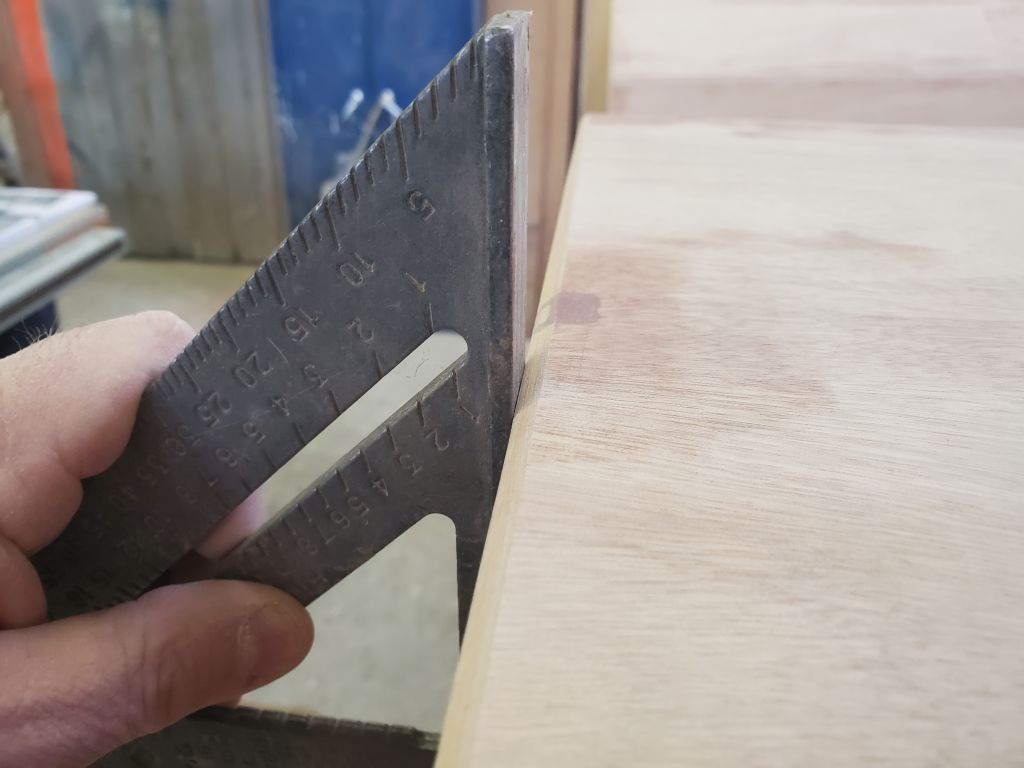
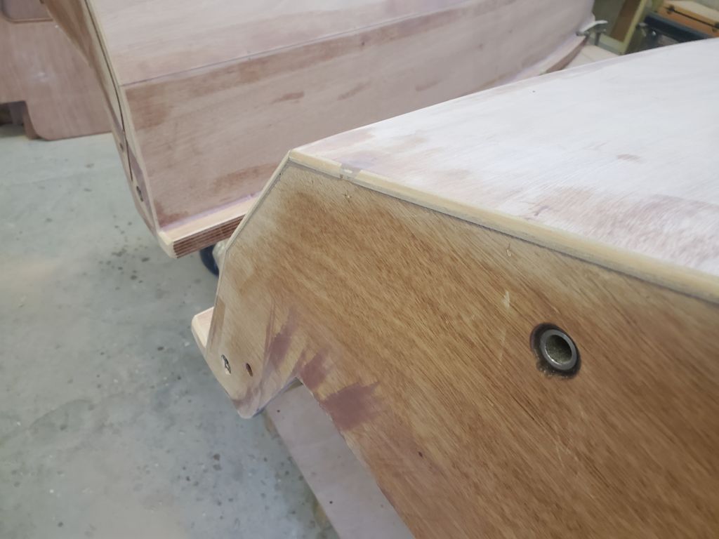
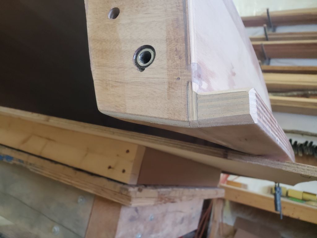
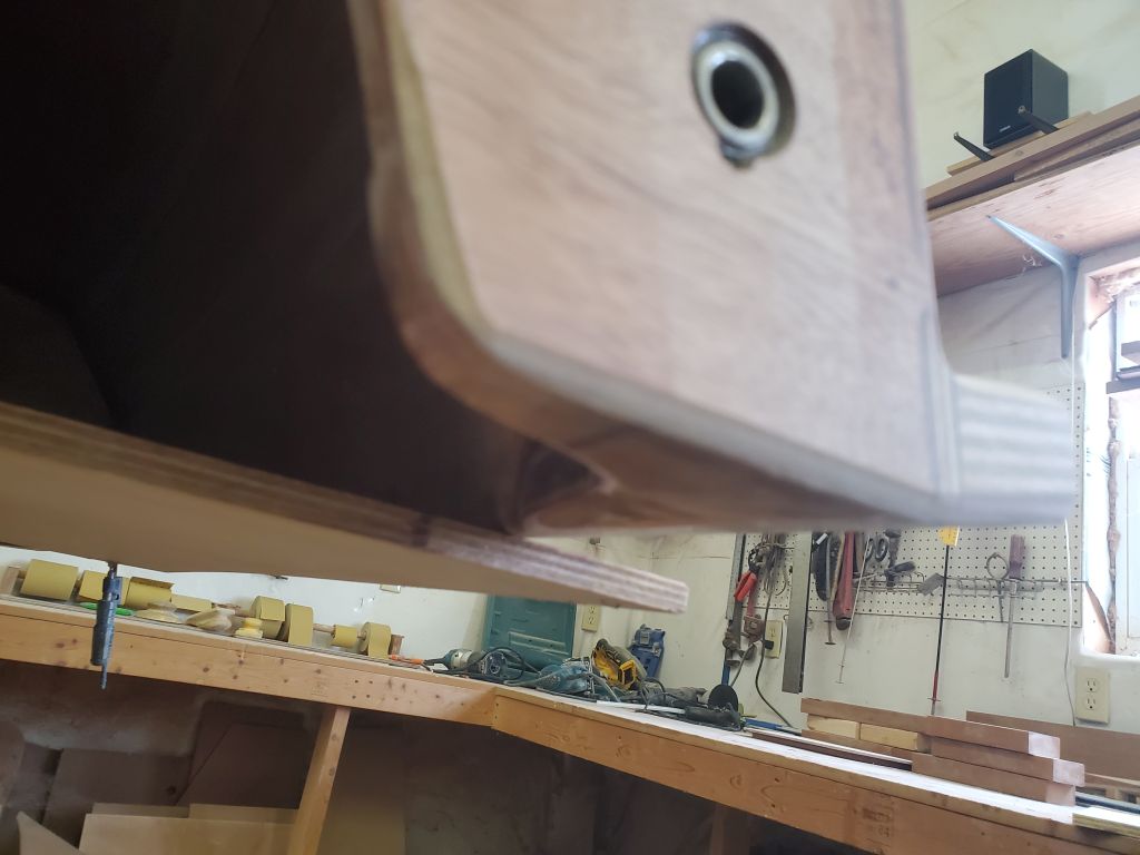
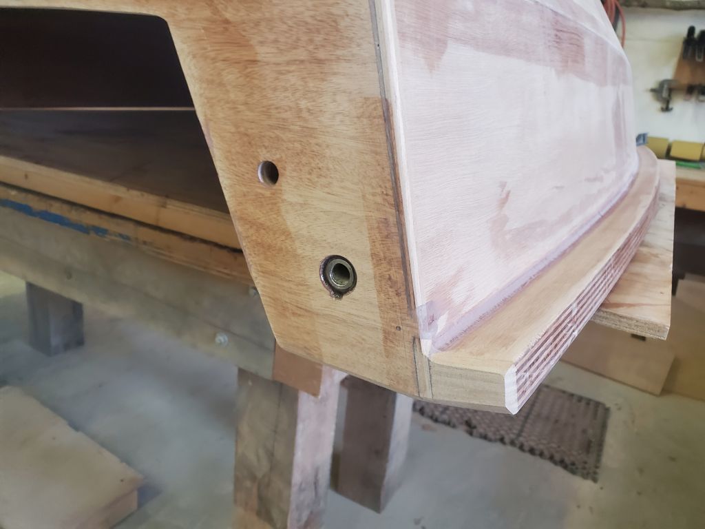
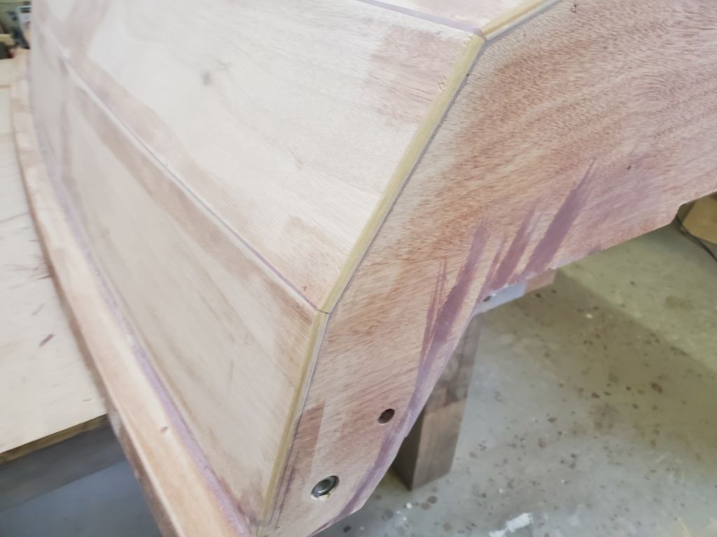
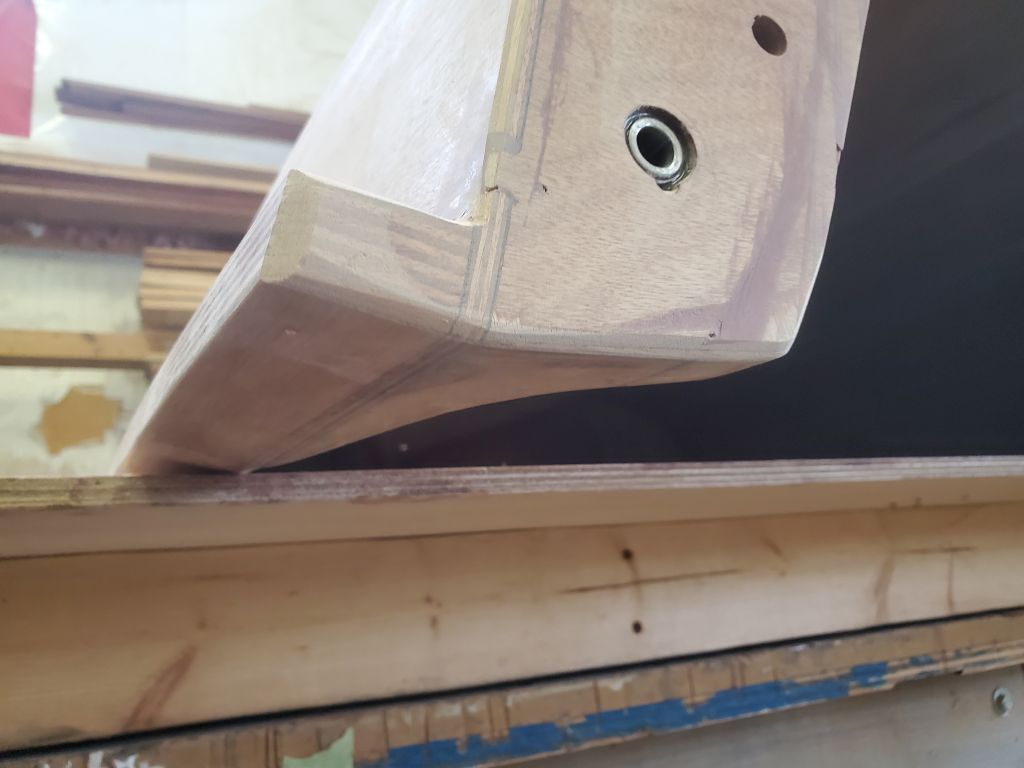
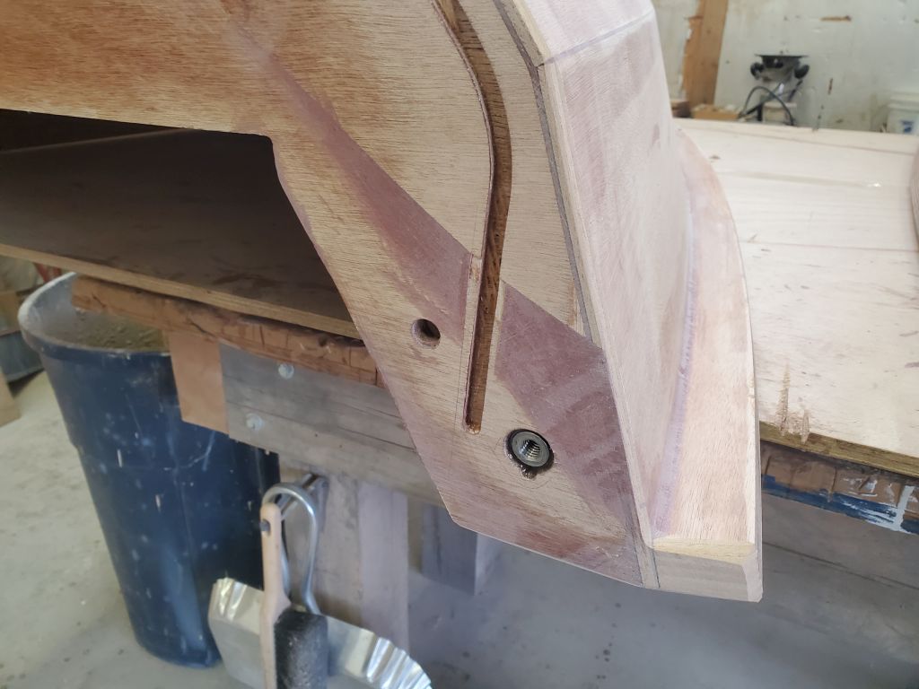
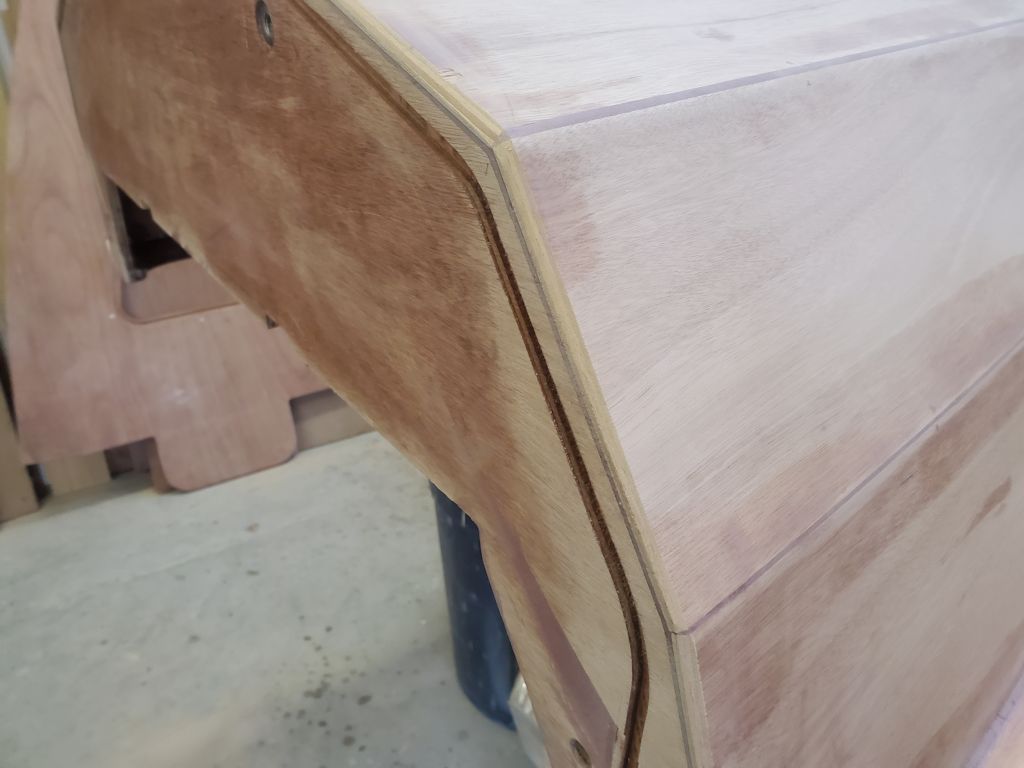
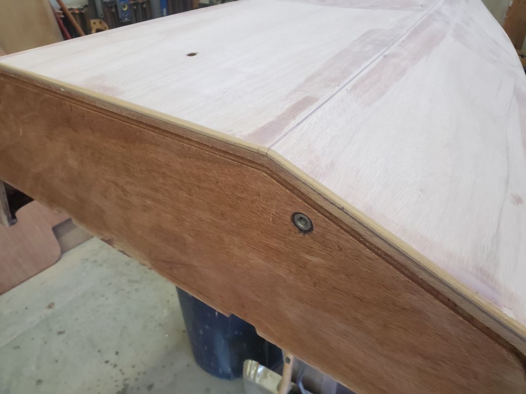
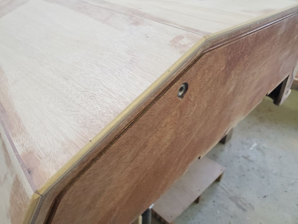
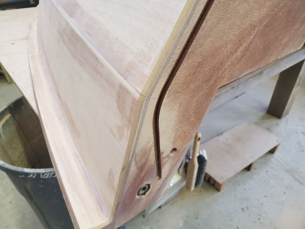
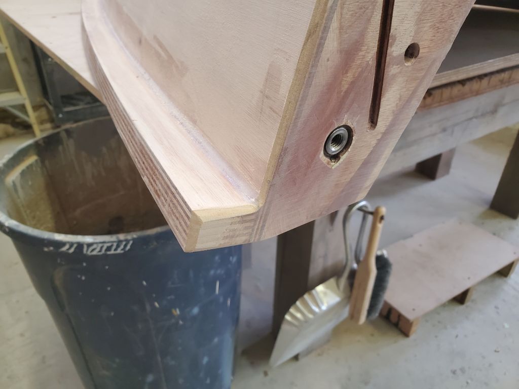
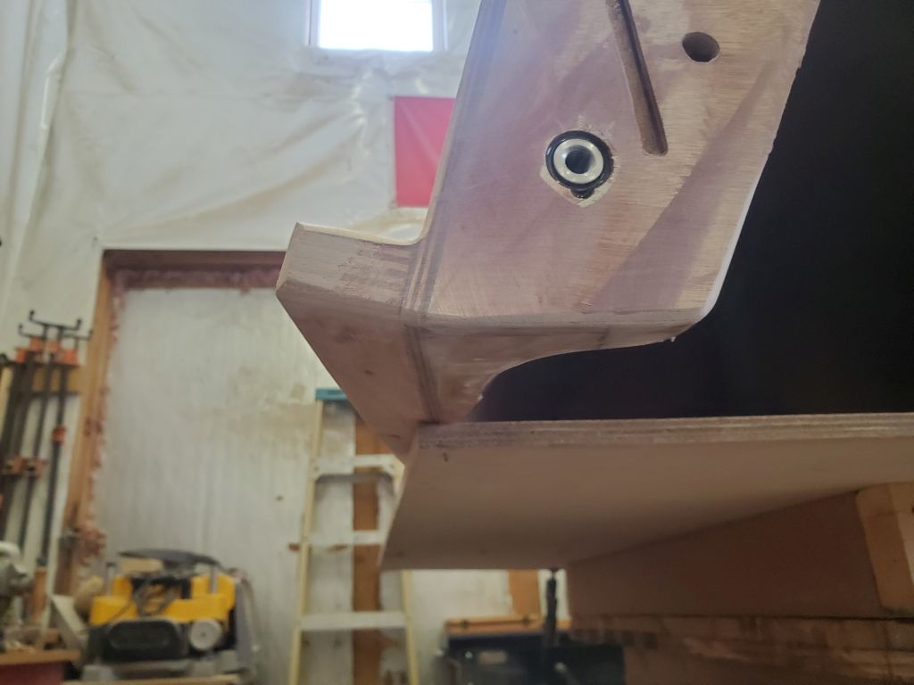
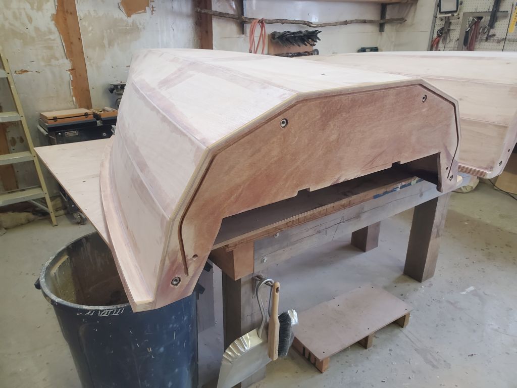
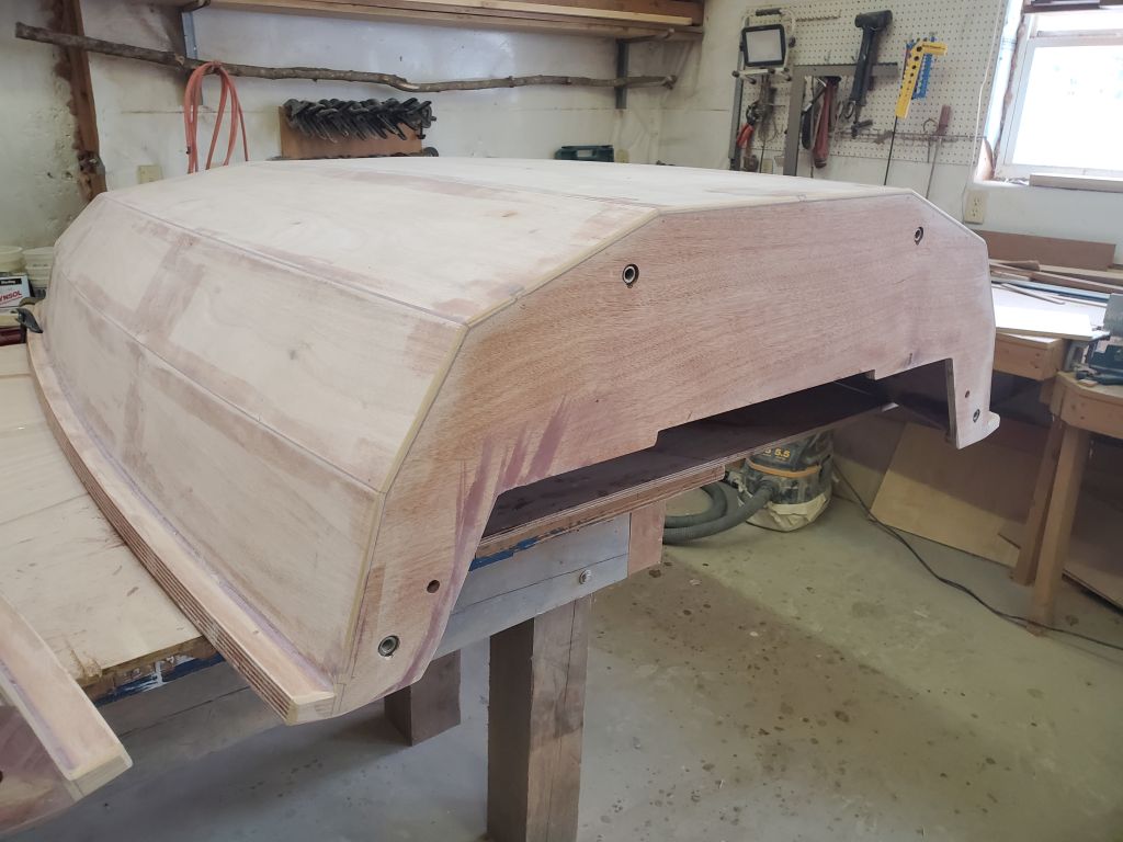
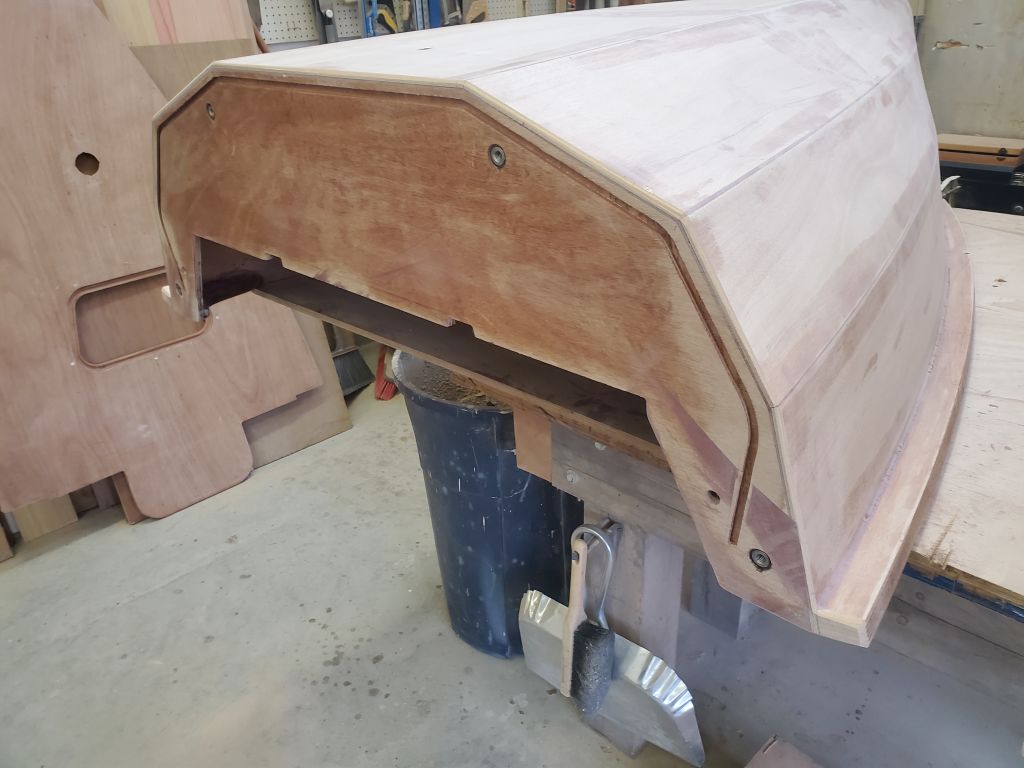
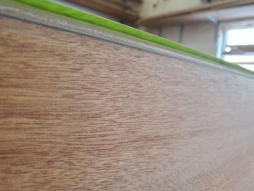
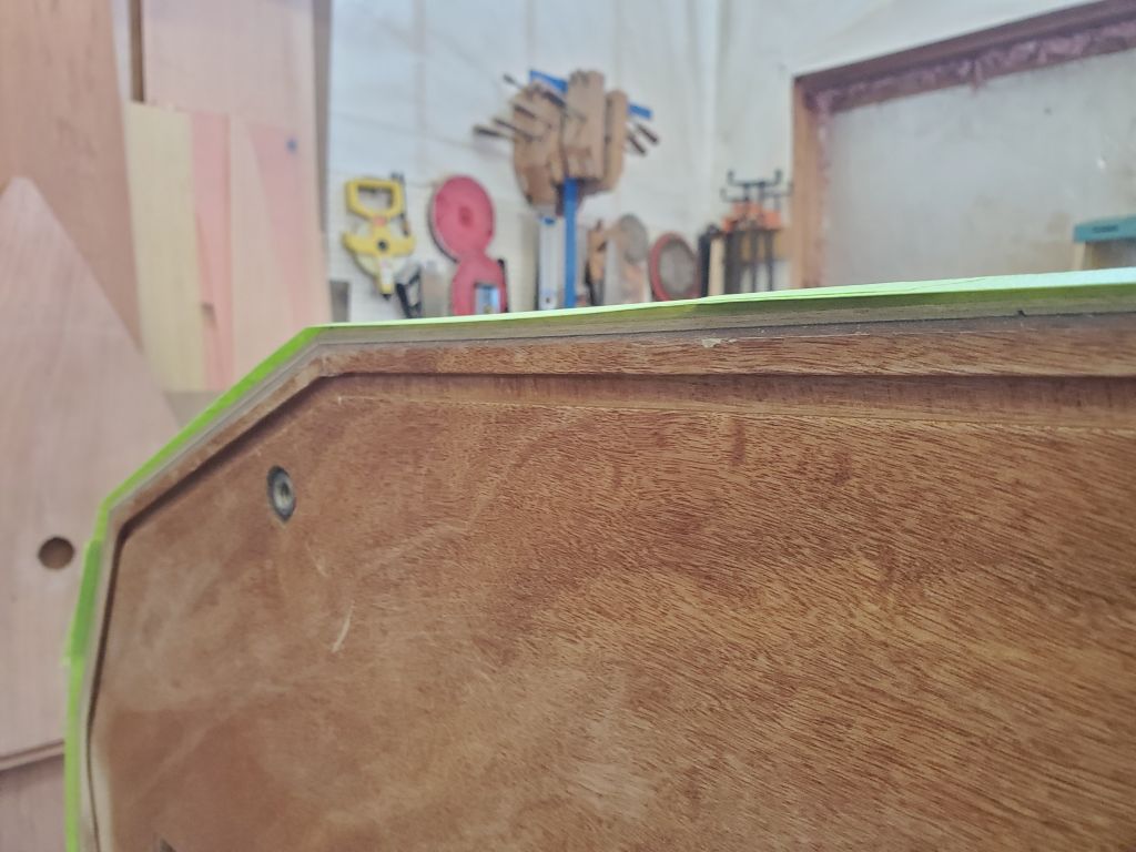
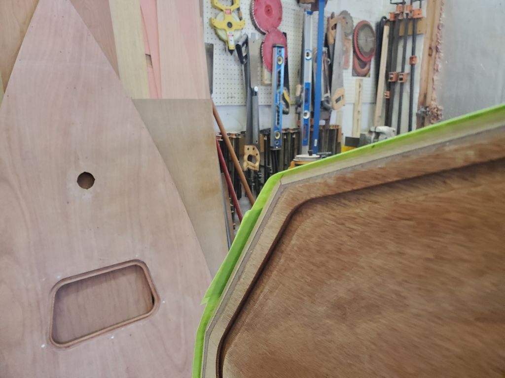
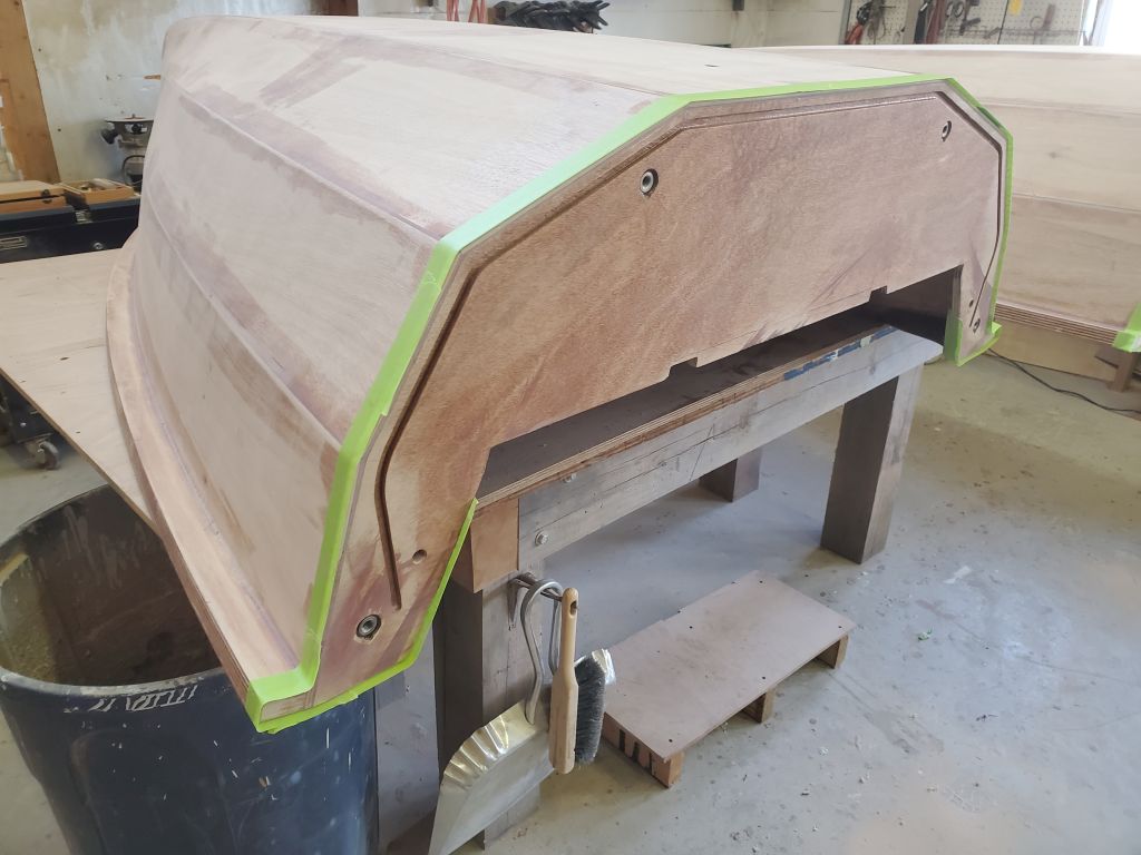
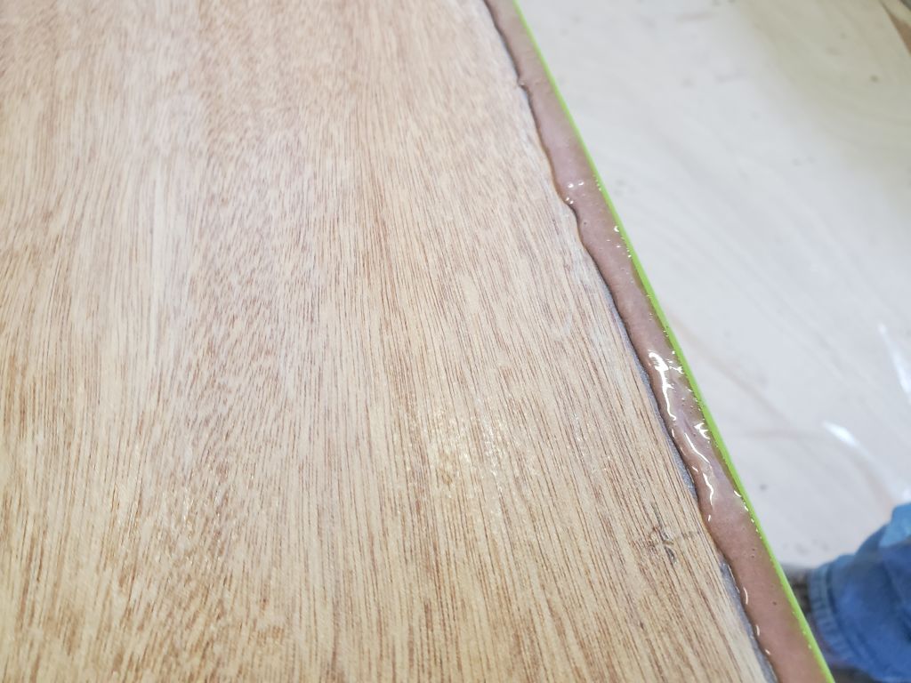
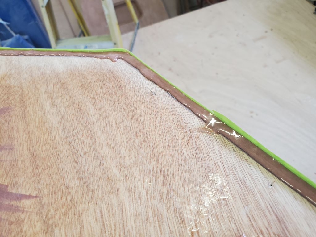
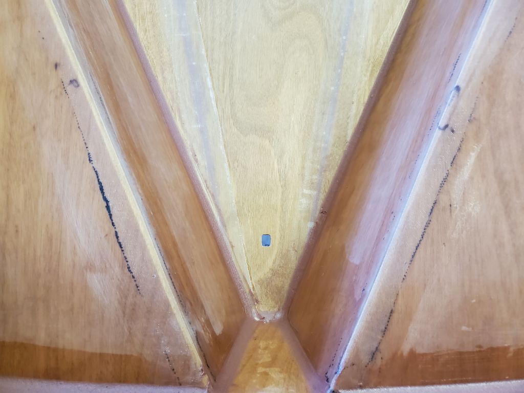
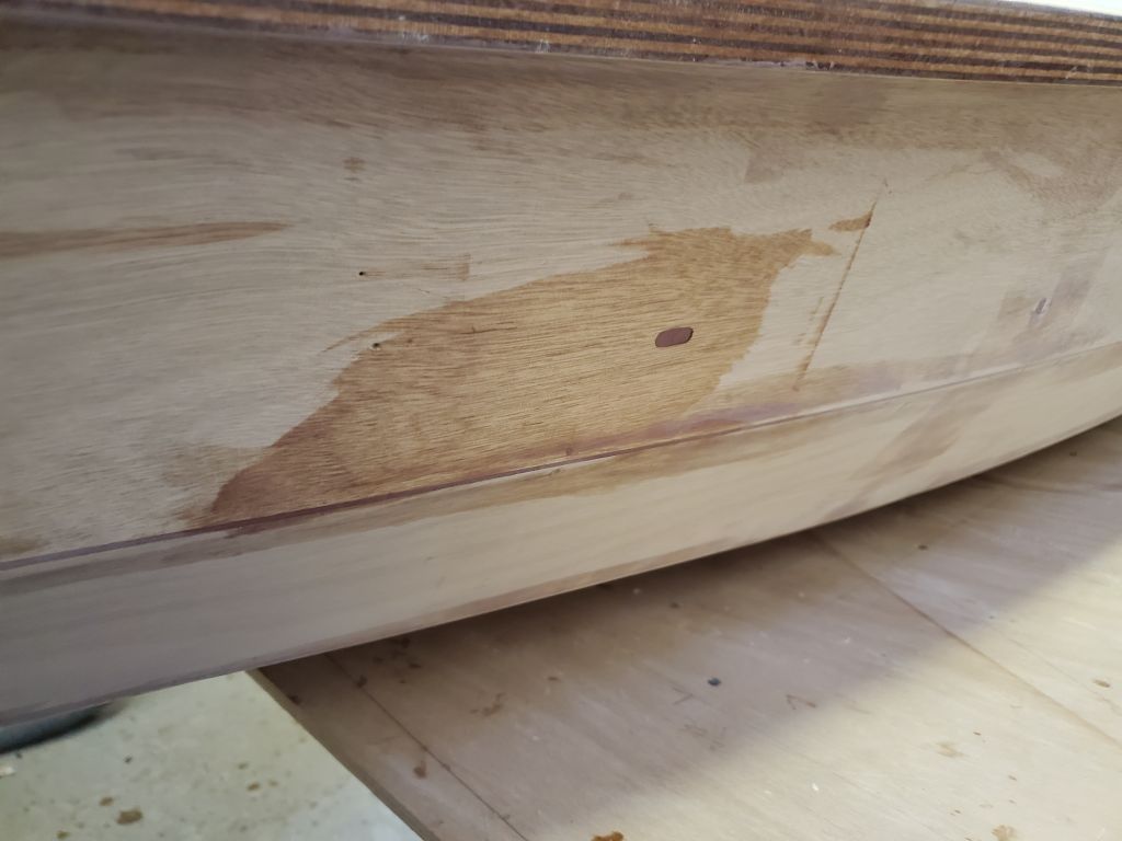
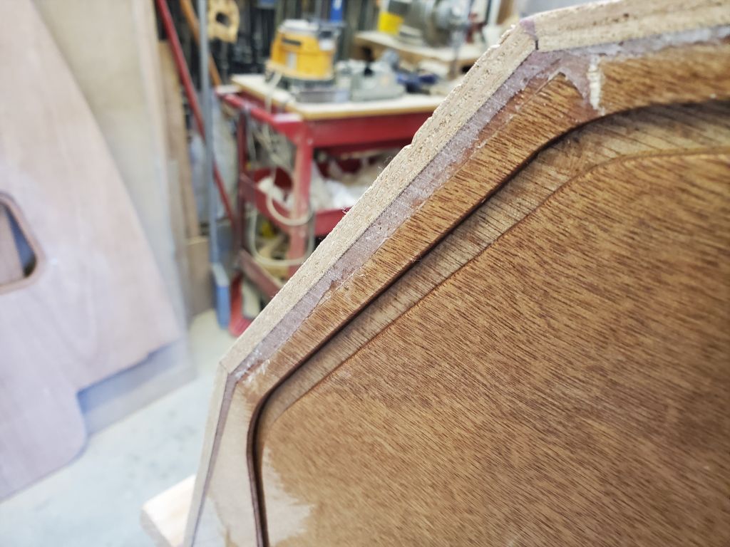
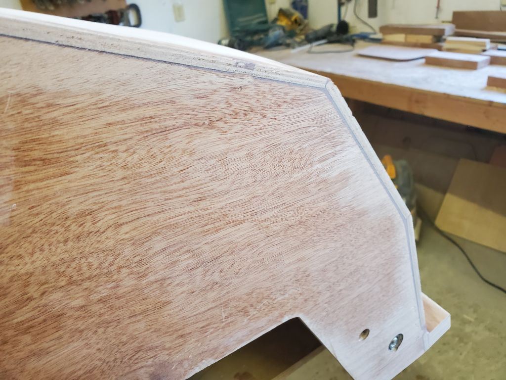
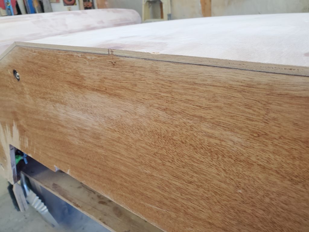
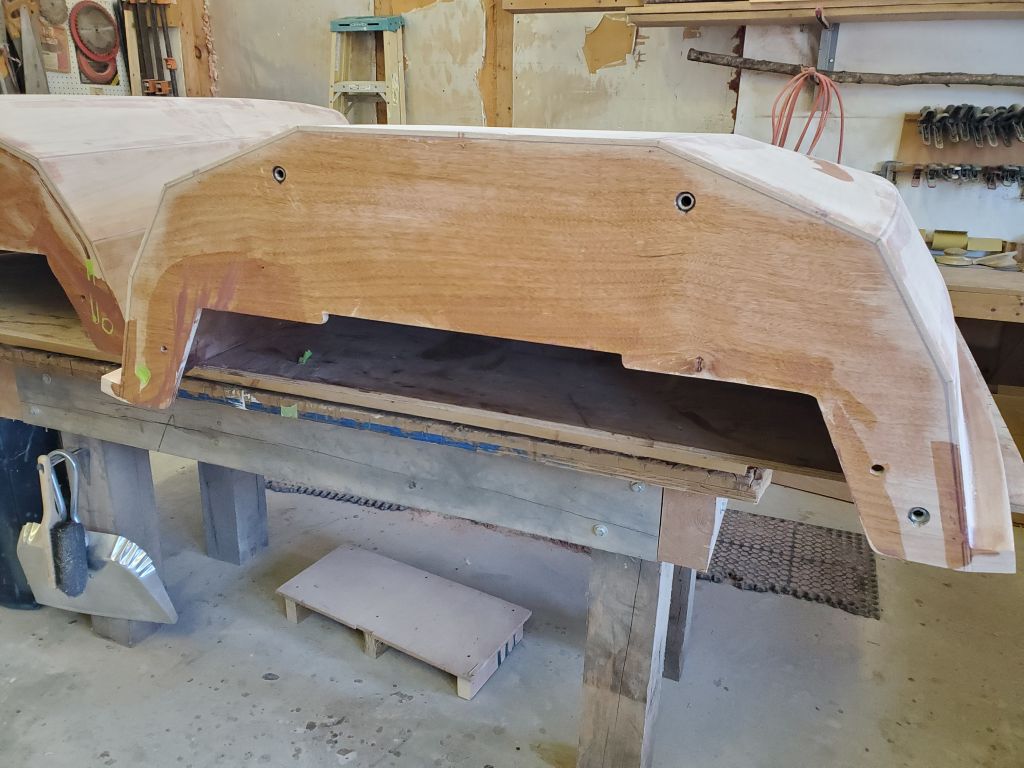
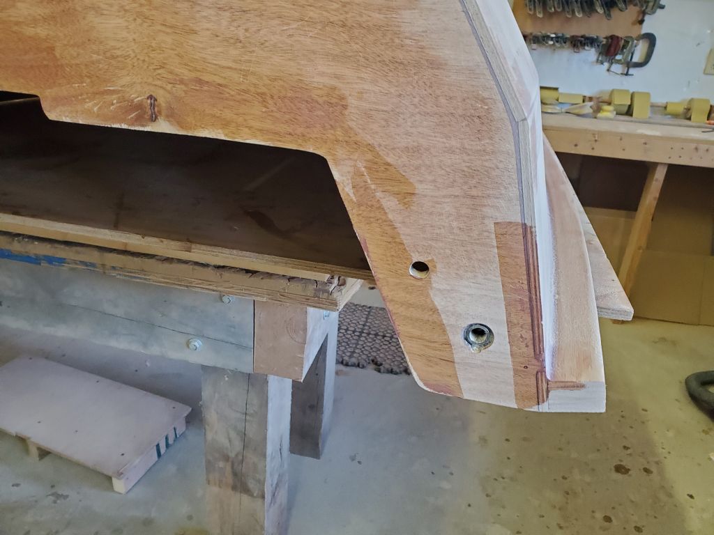
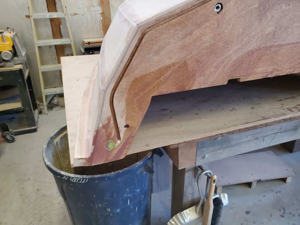
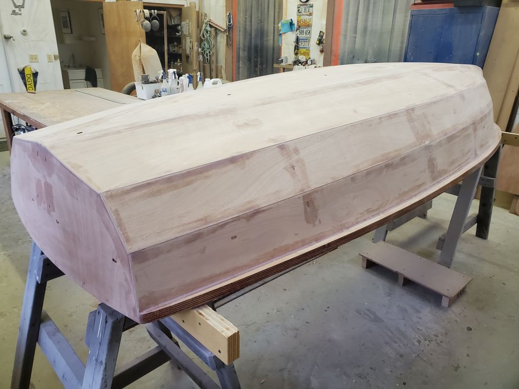
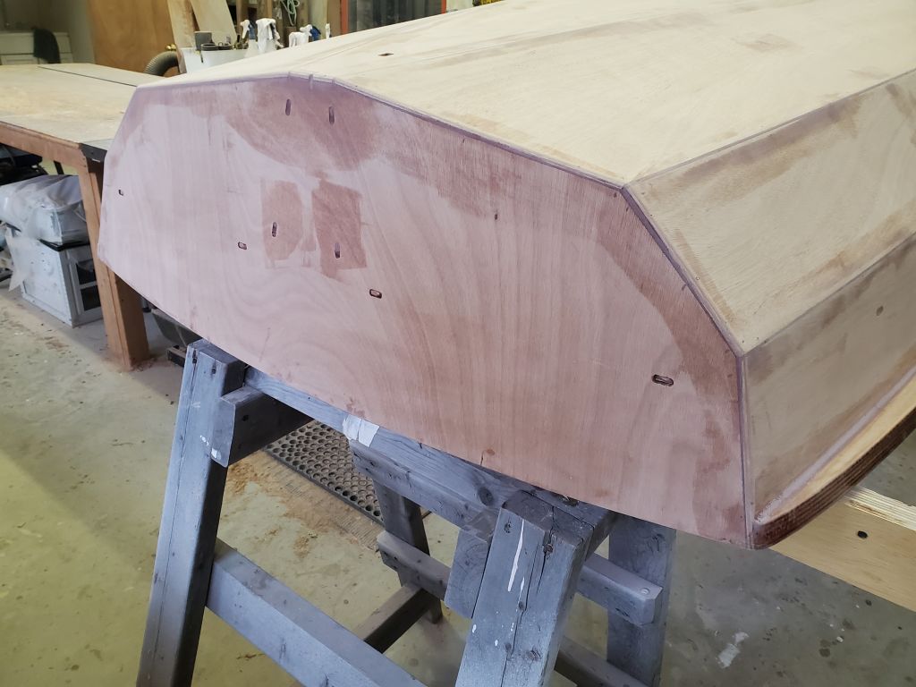
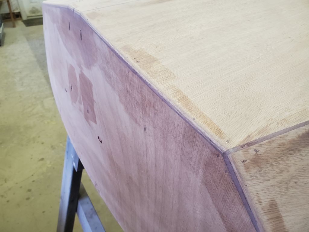
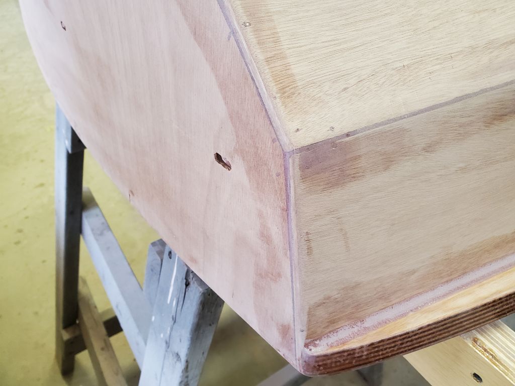
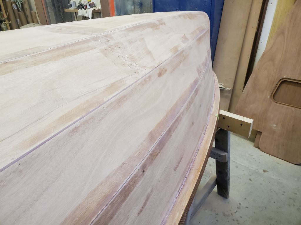
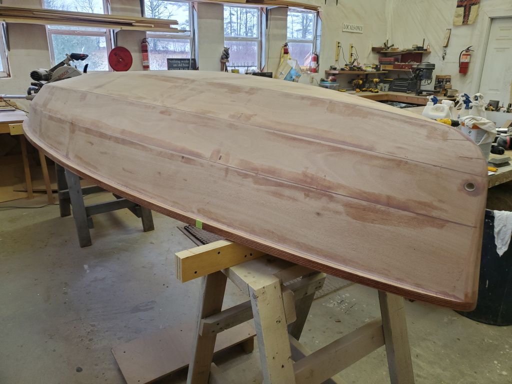
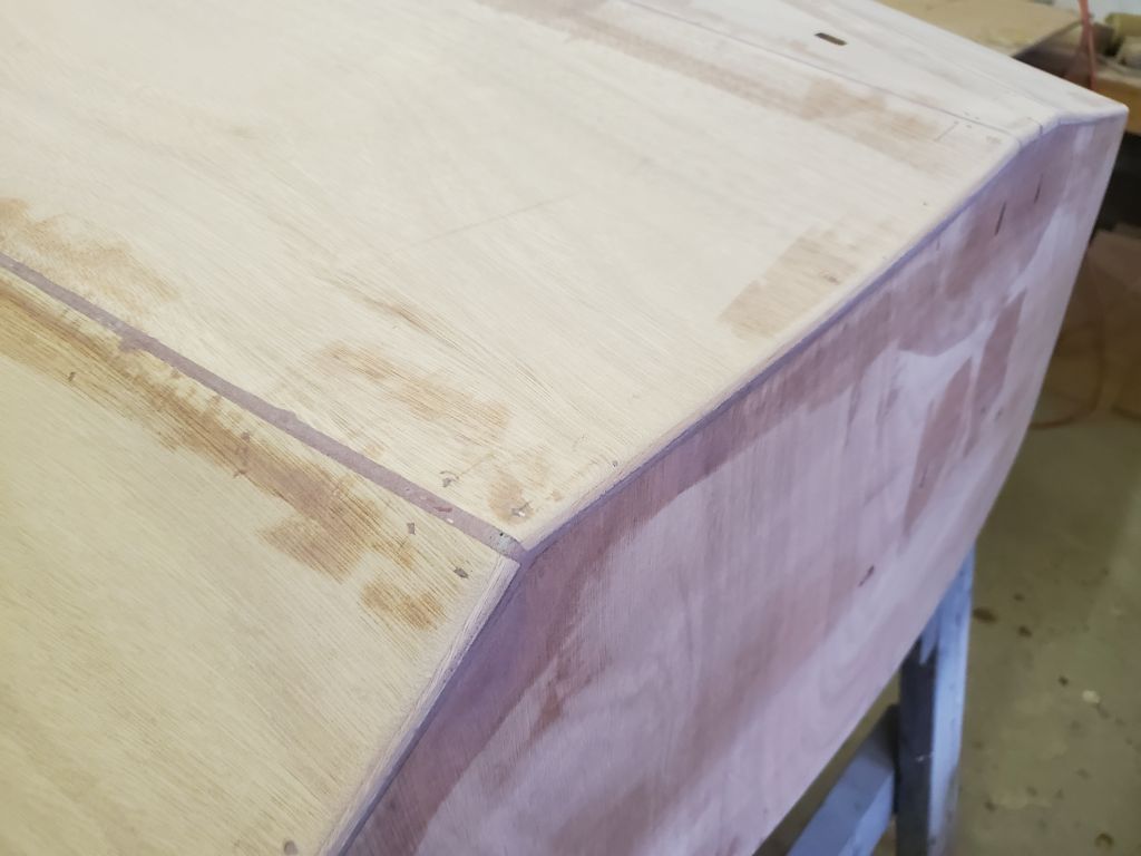
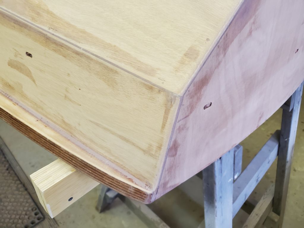
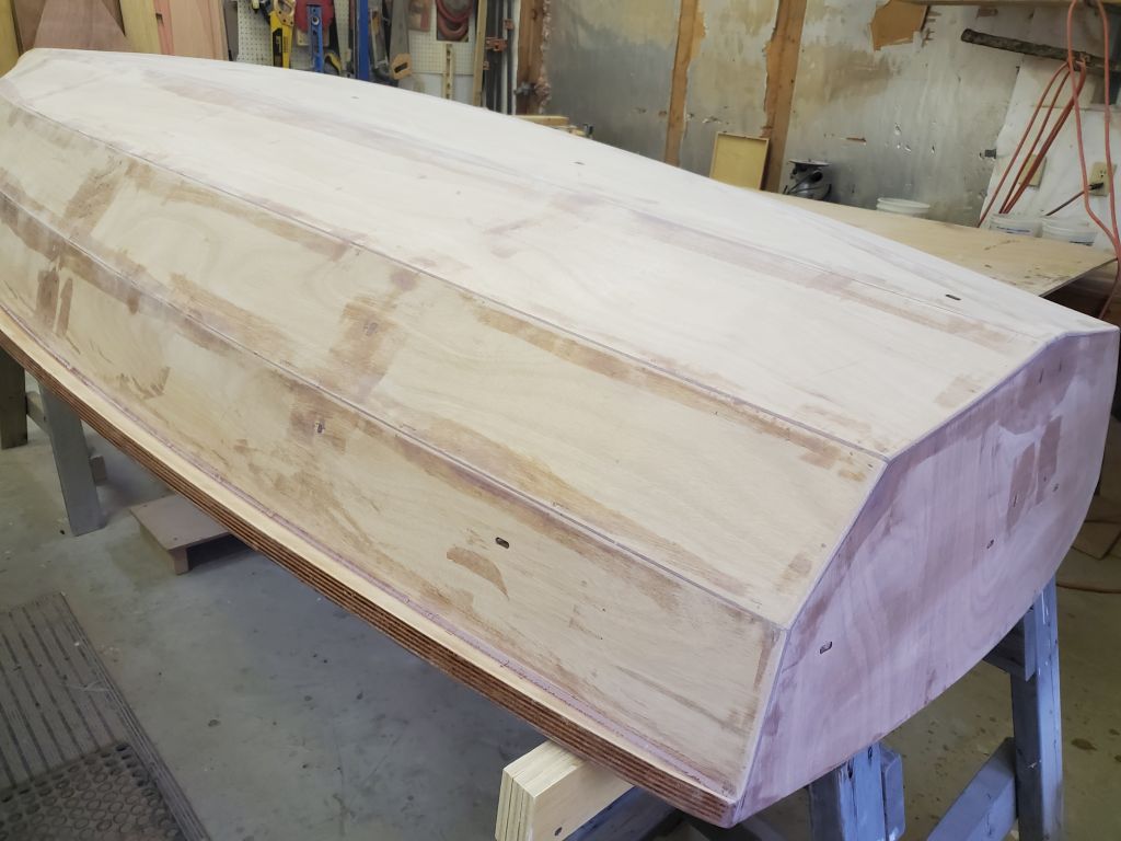
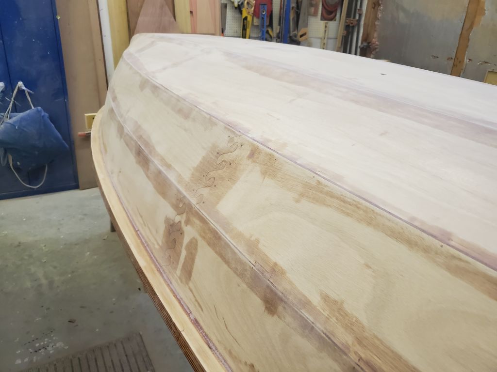
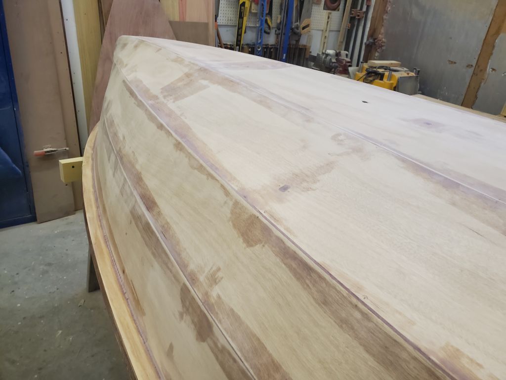
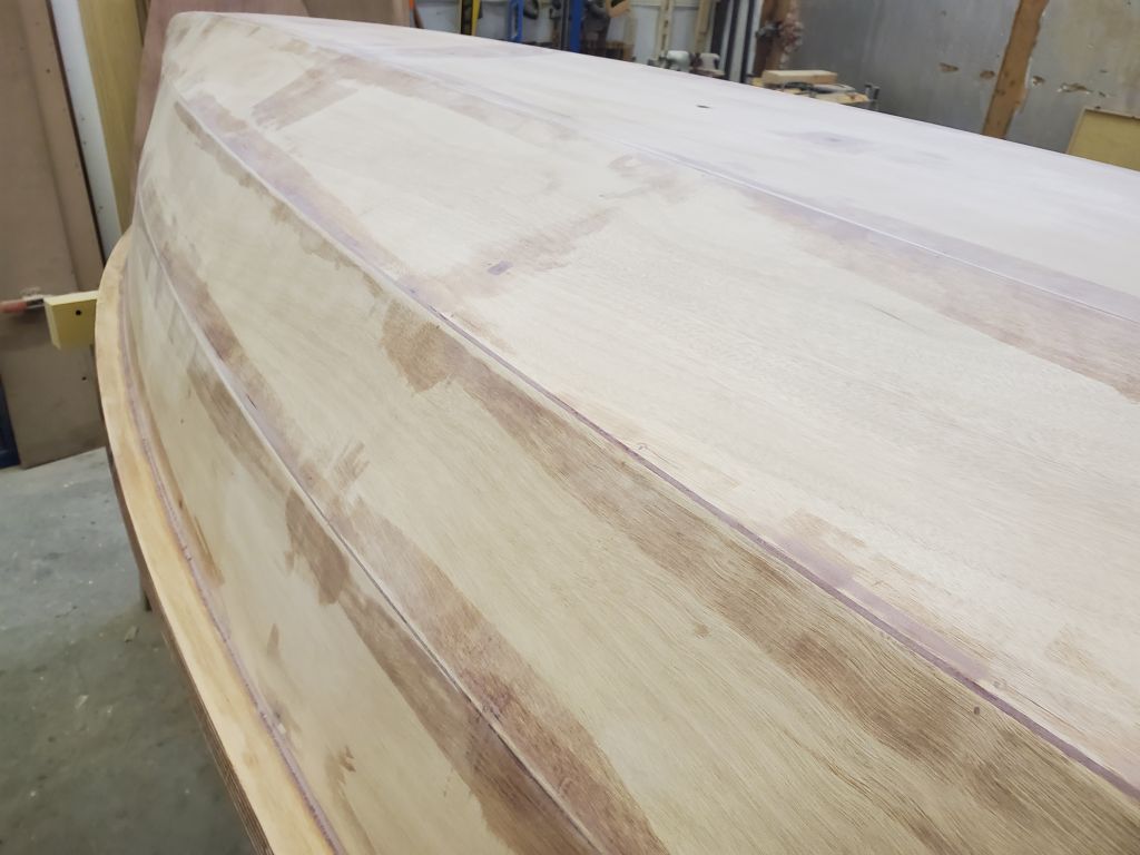
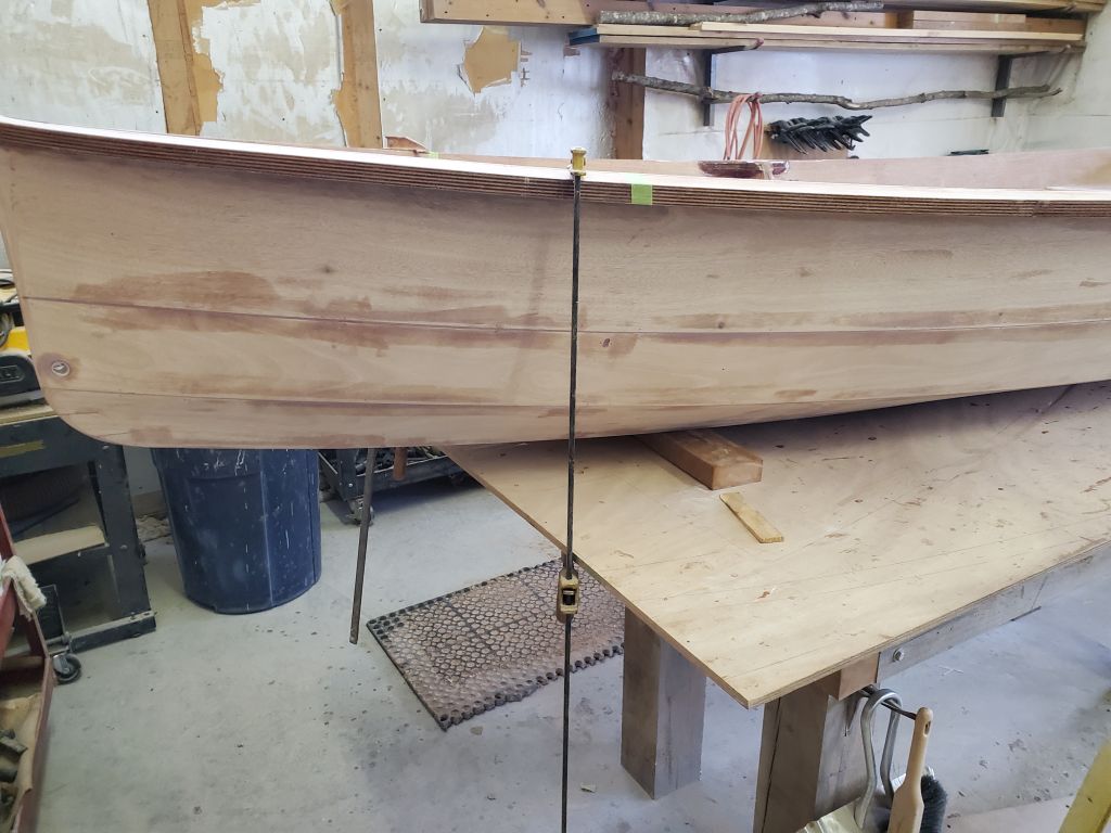
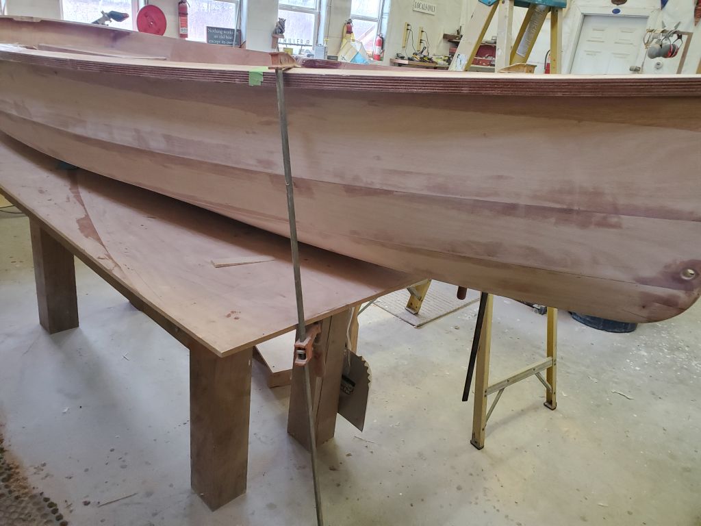
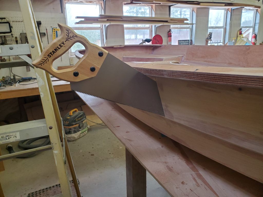
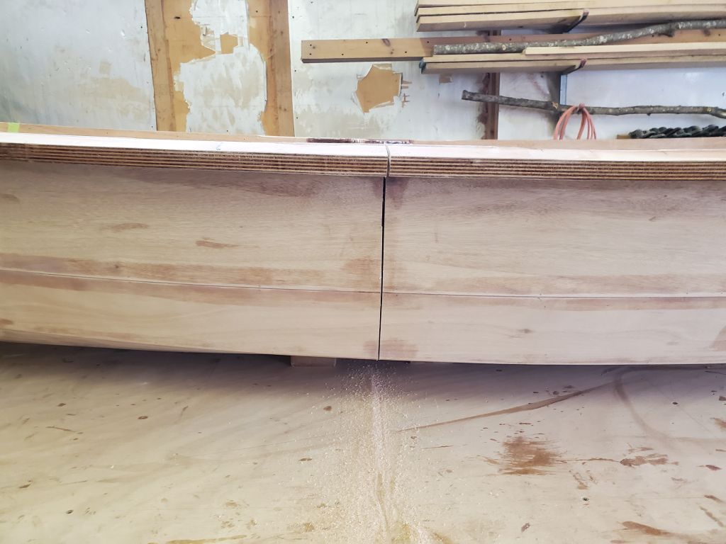
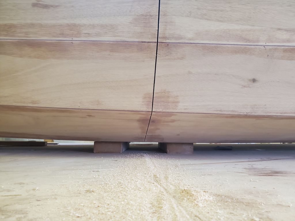
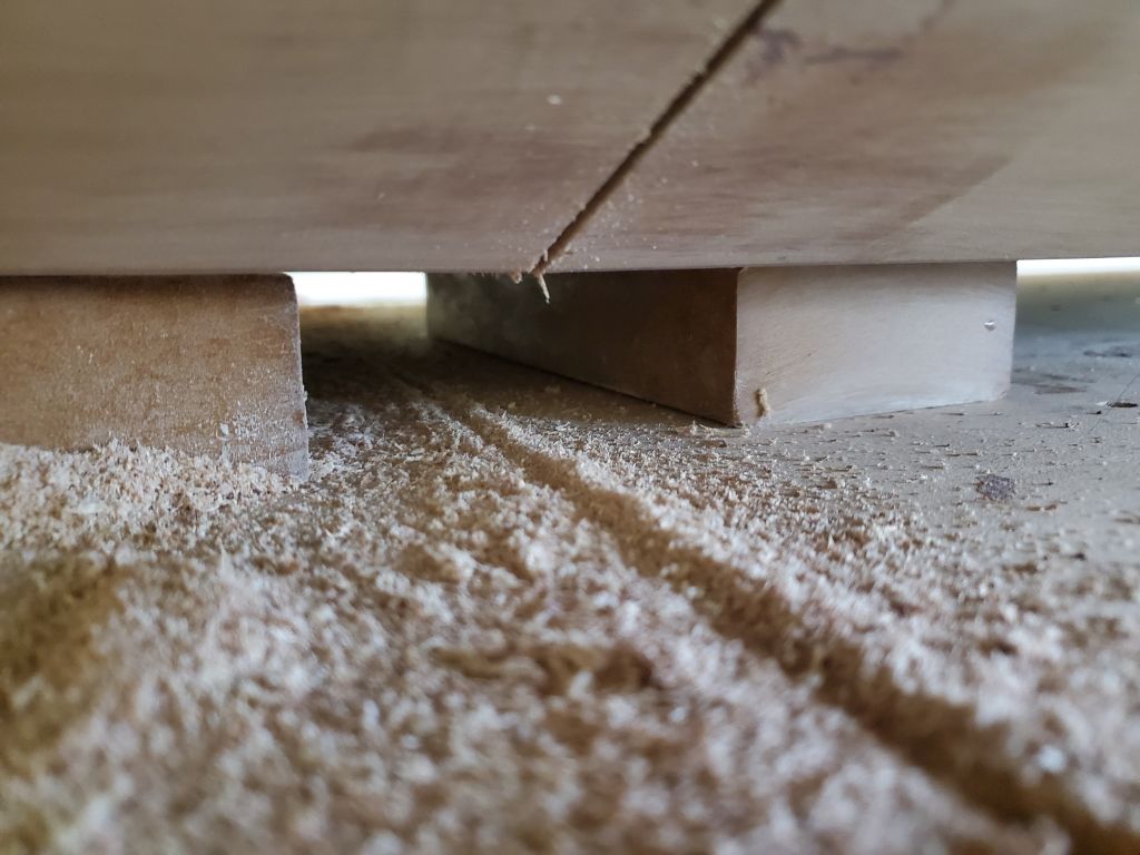
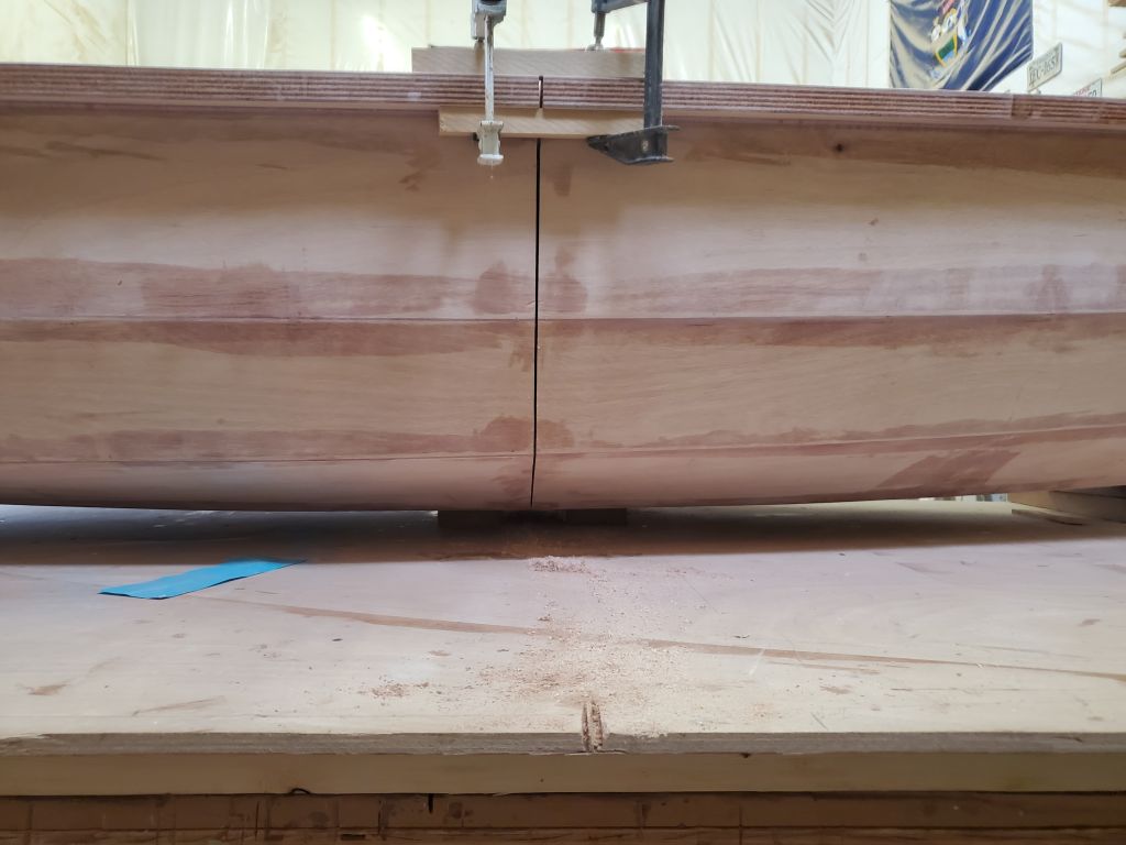
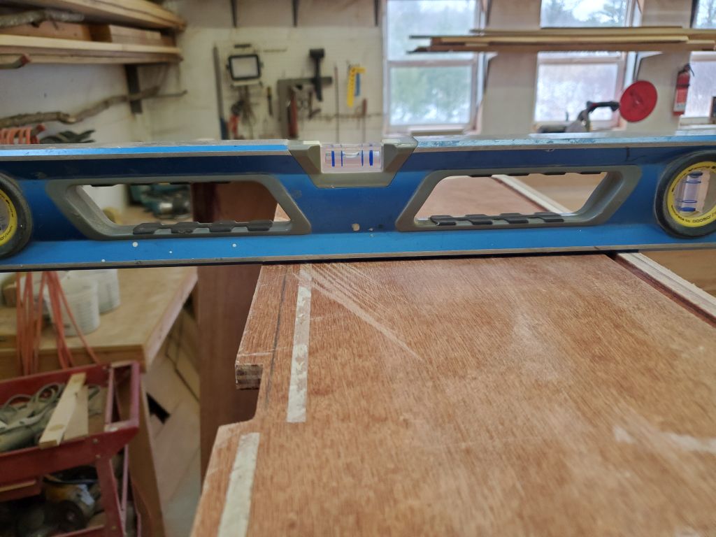
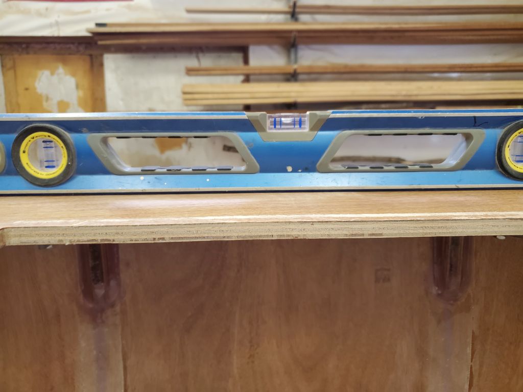
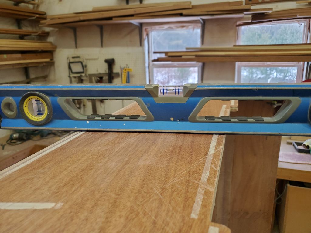
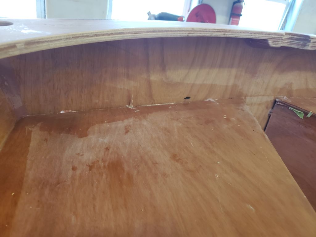
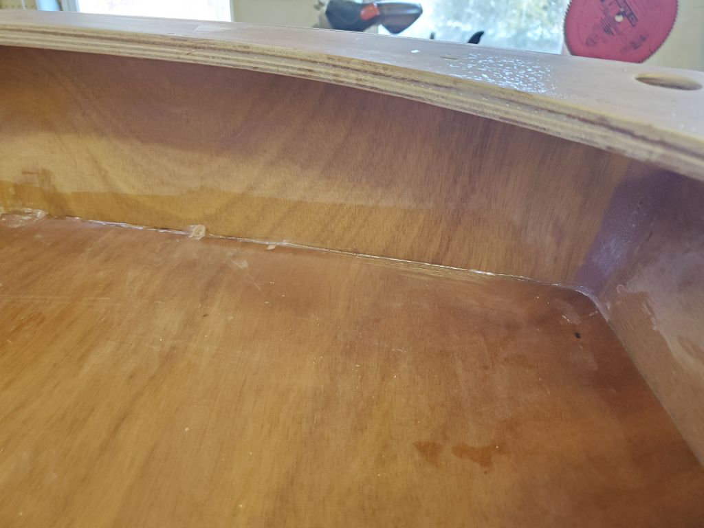
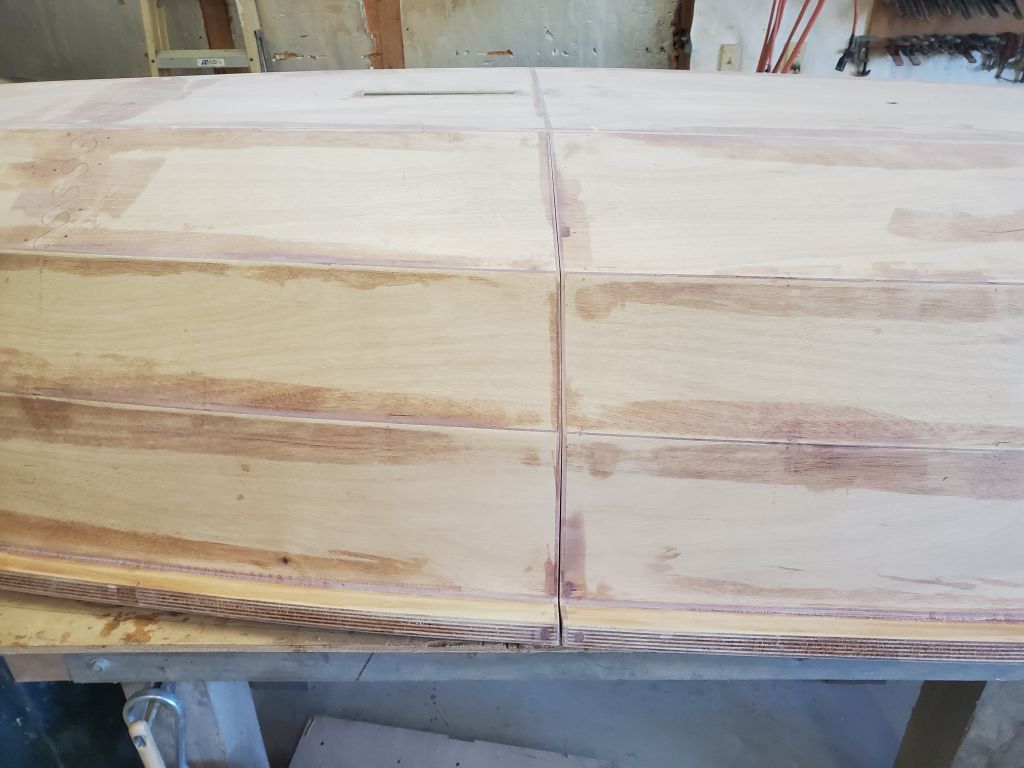
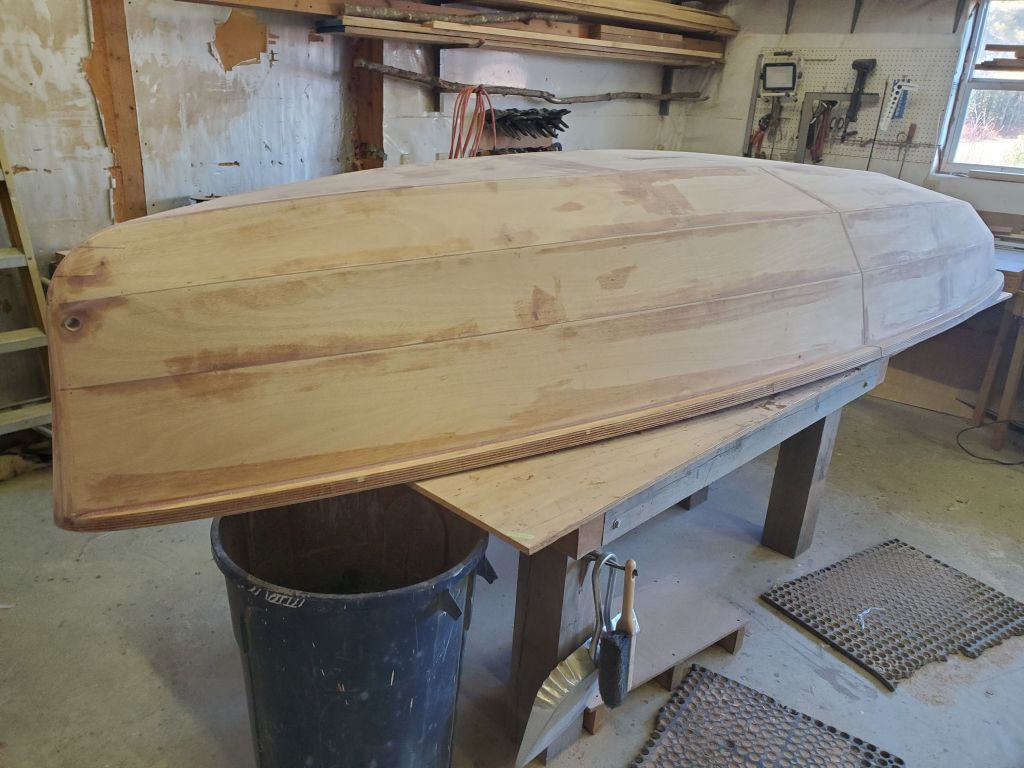
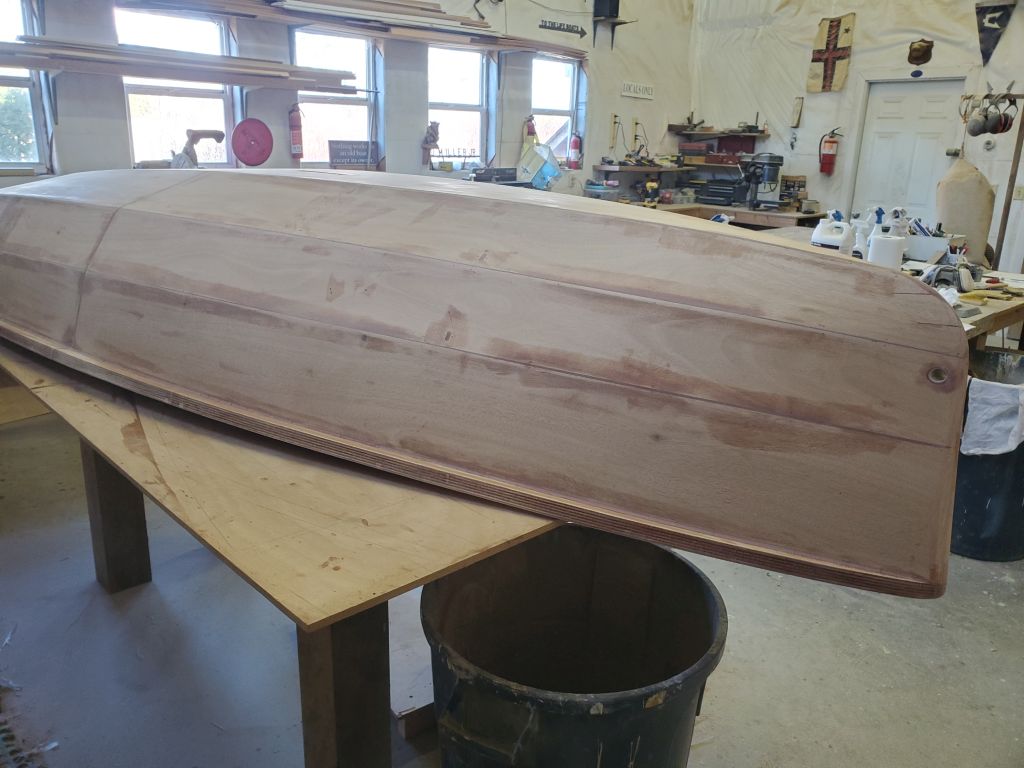
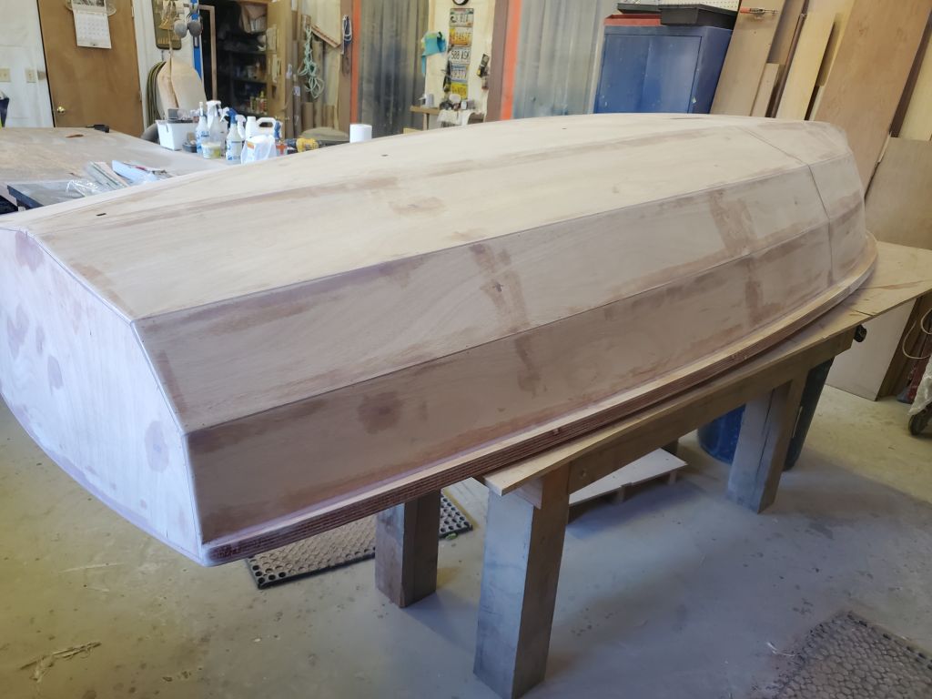
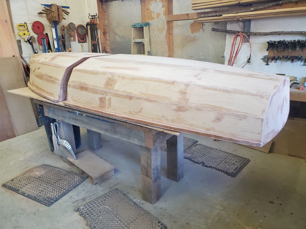
I turned the boat upside down on the table–not the easiest thing to do now that I’d gotten used to the easy-to-maneuver boat halves–and prepared to do some minor fairing work at the hull seam.
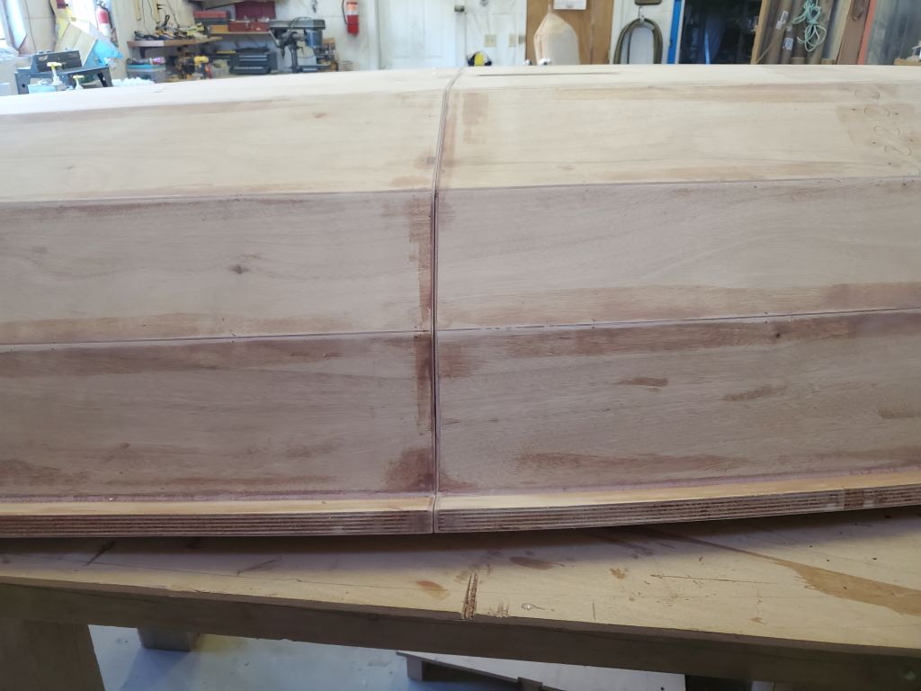
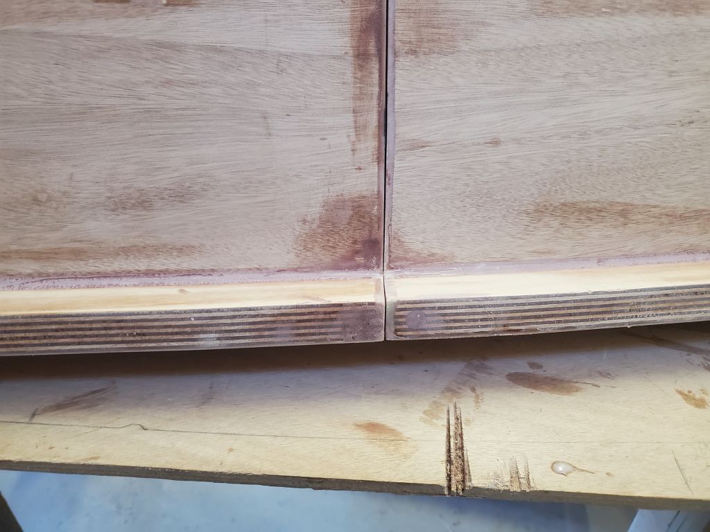
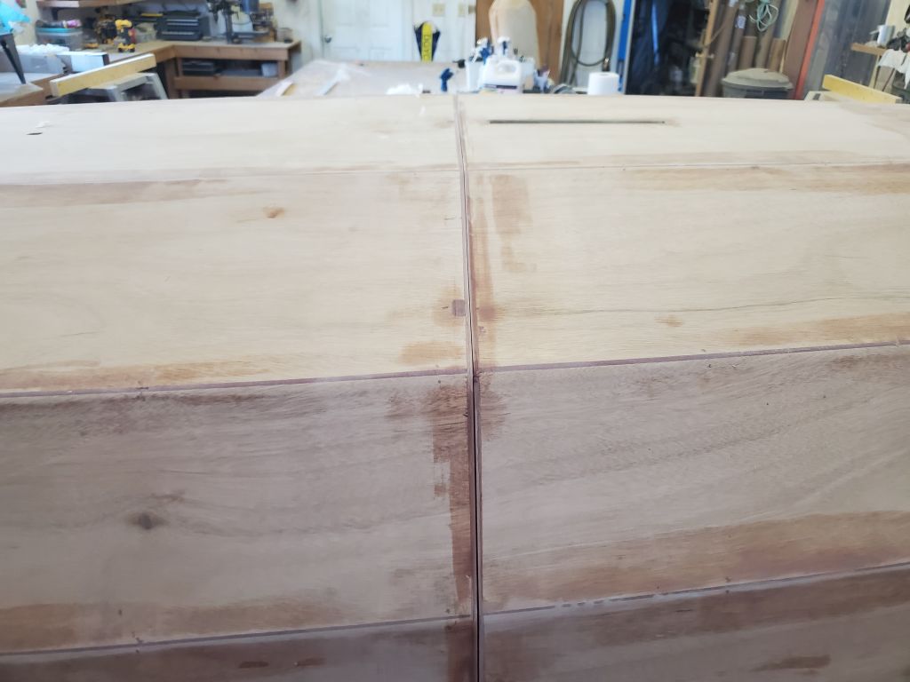
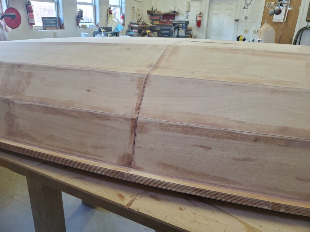
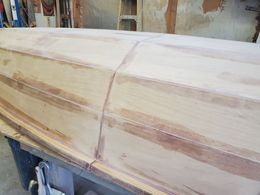
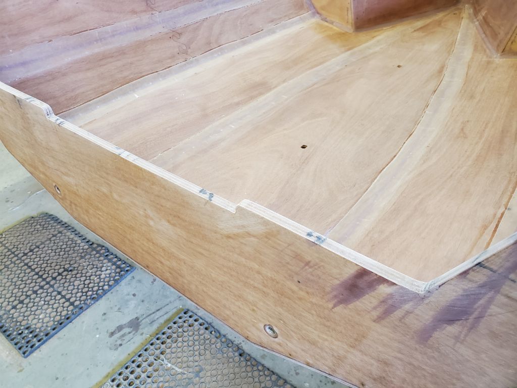
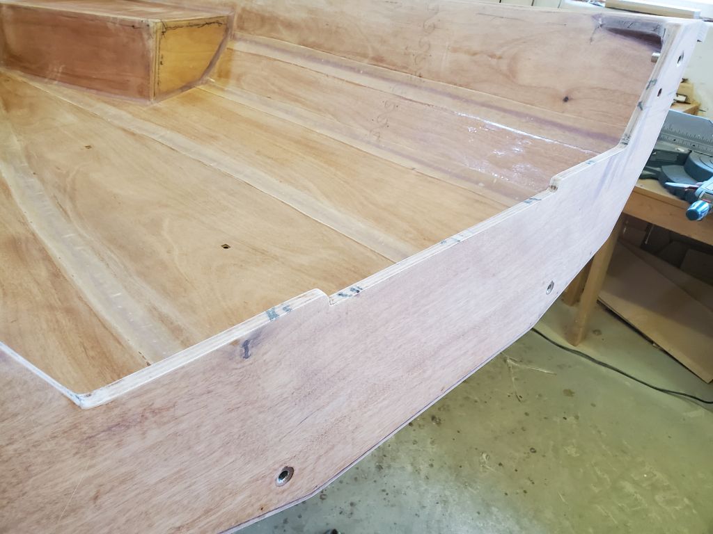
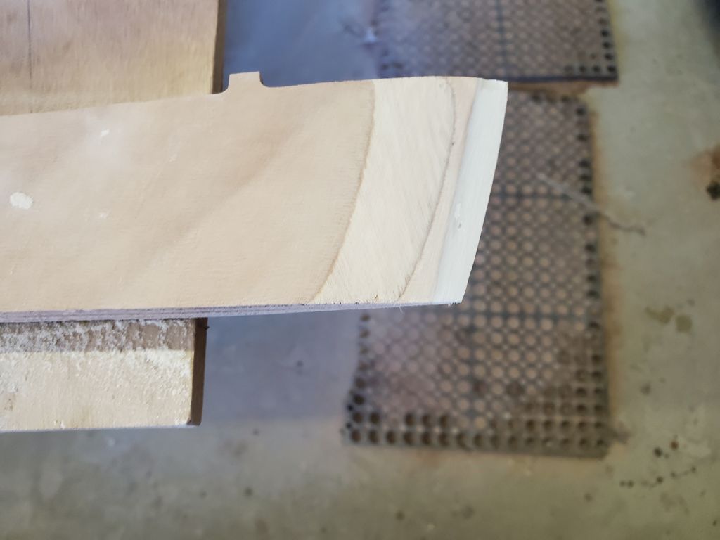
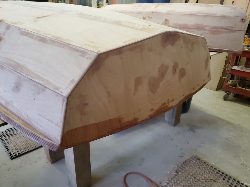
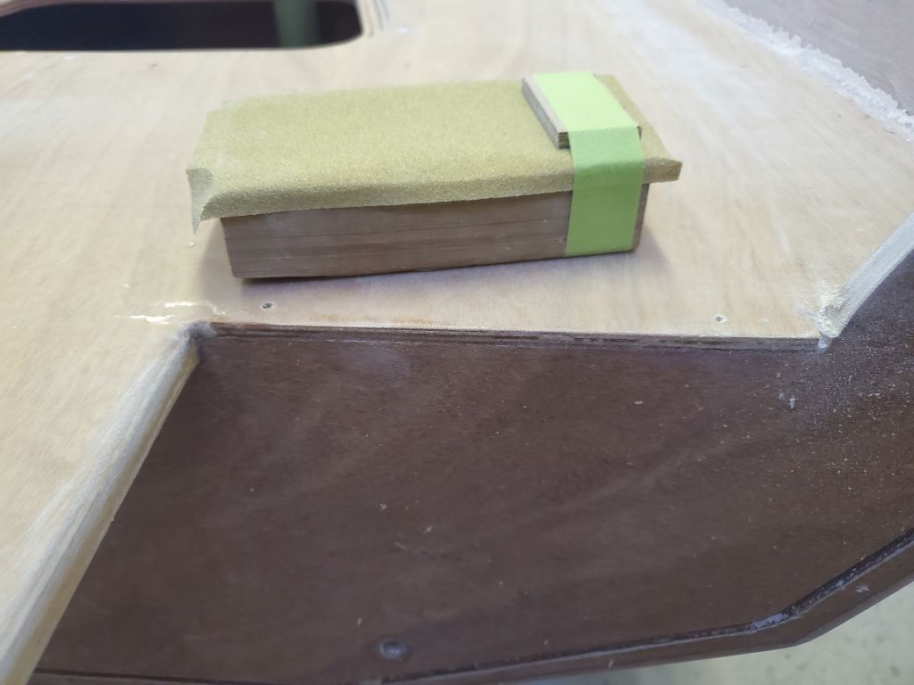
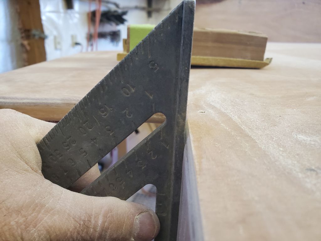
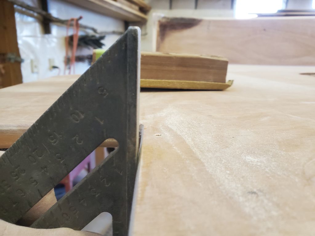
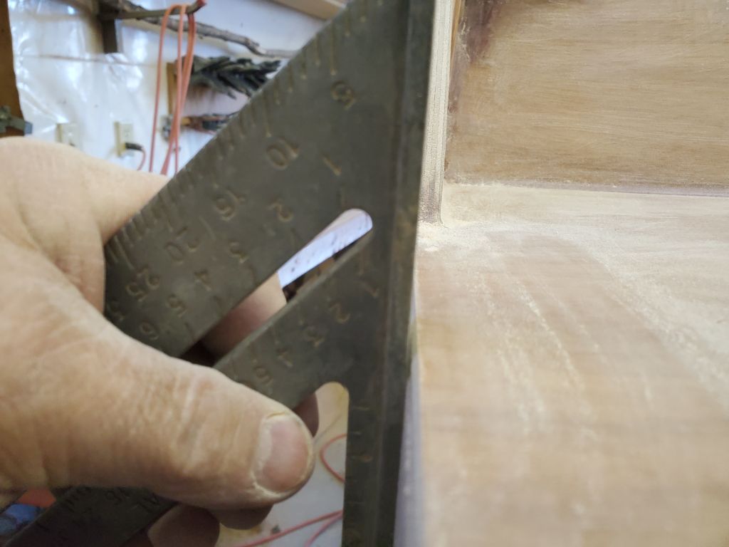
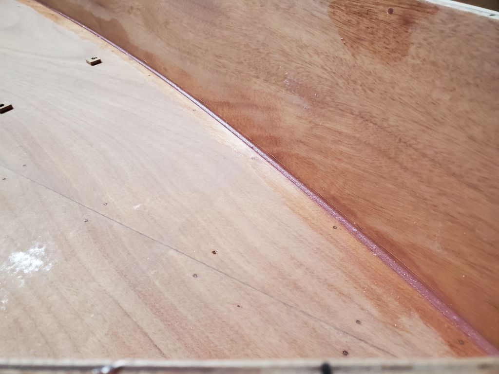
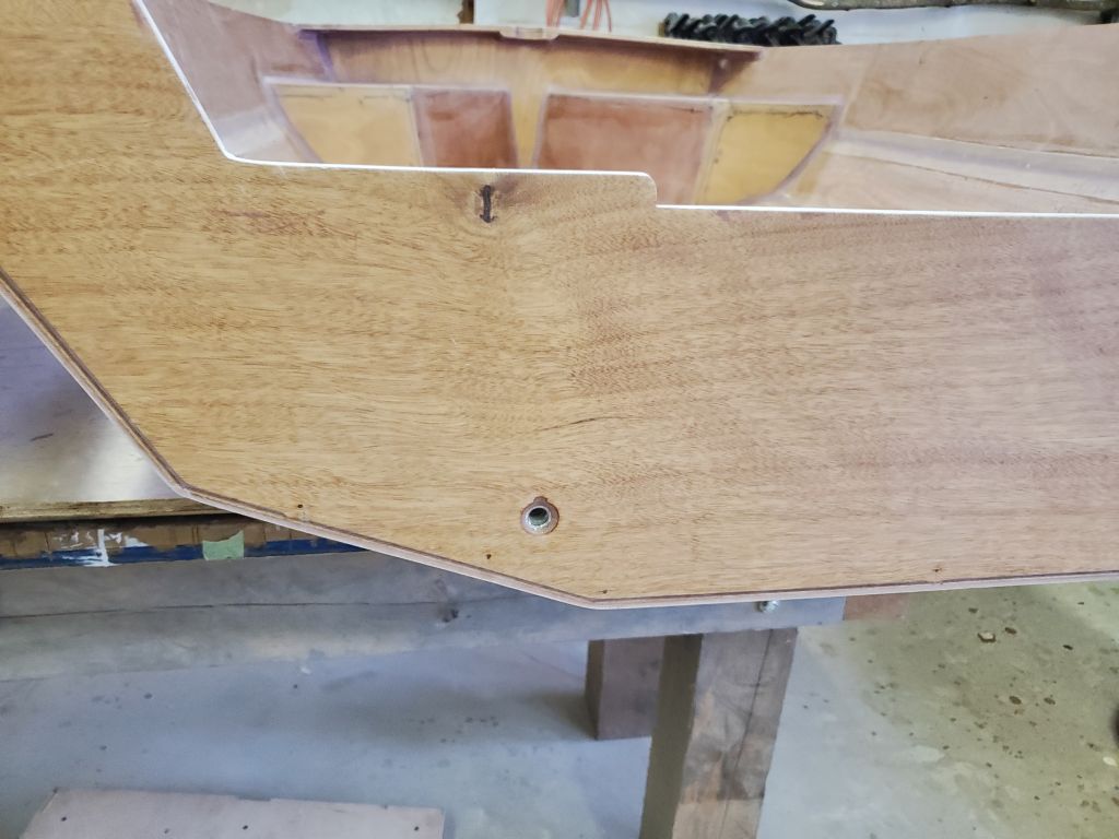
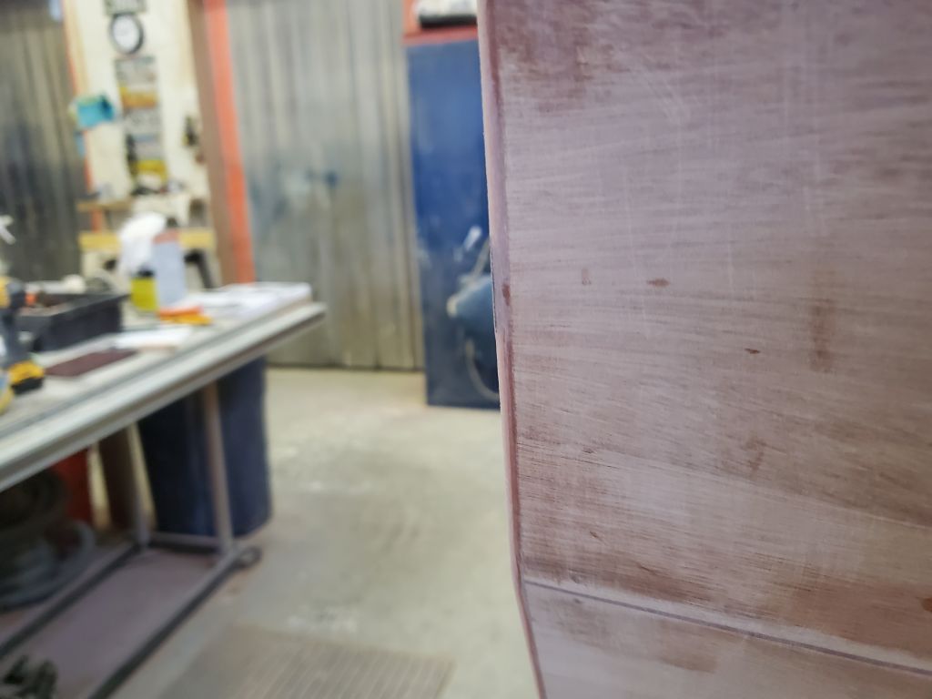
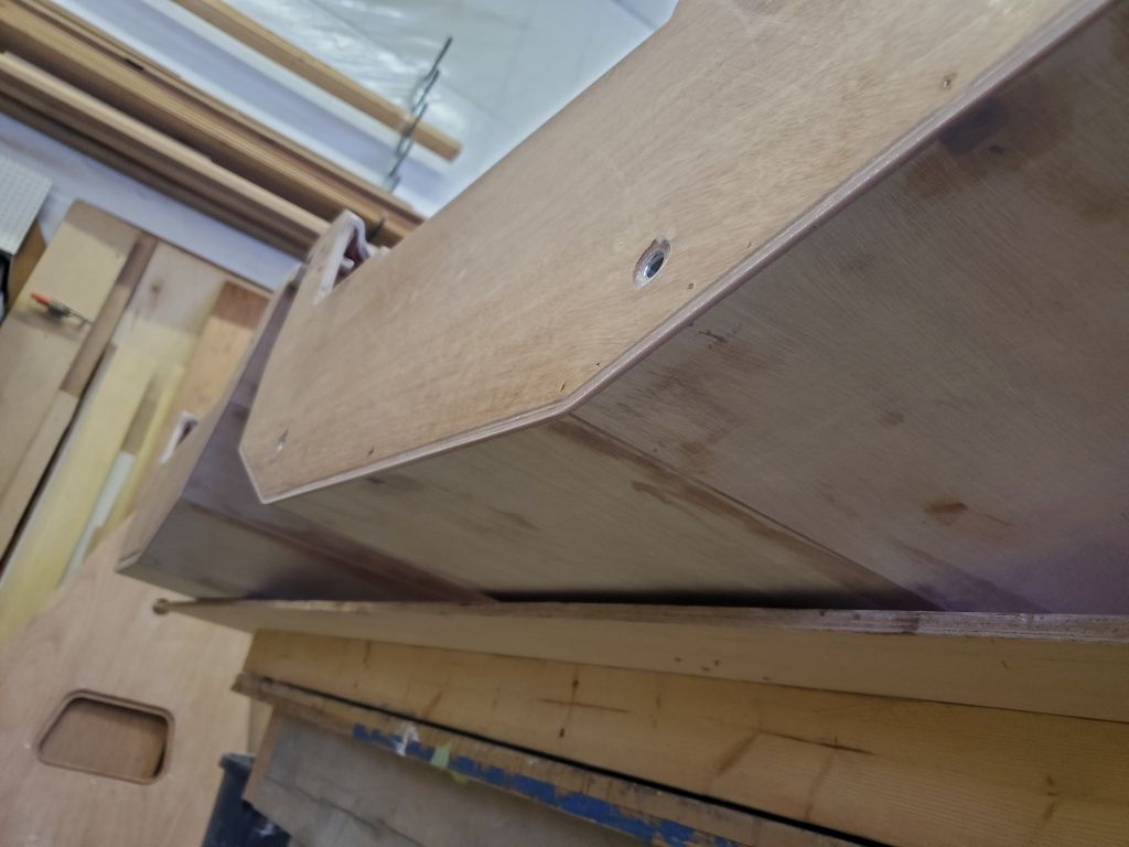
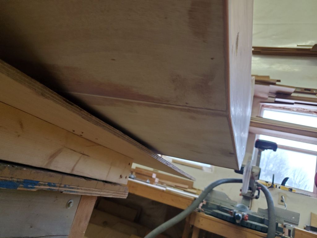
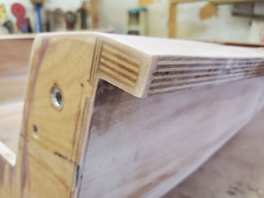
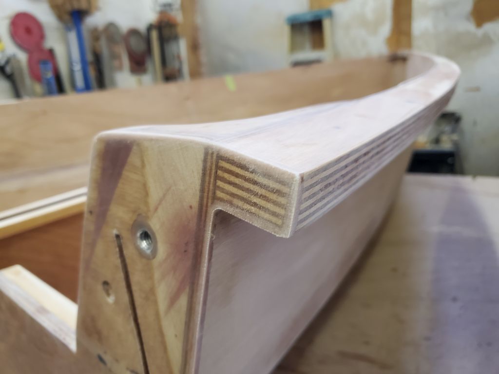
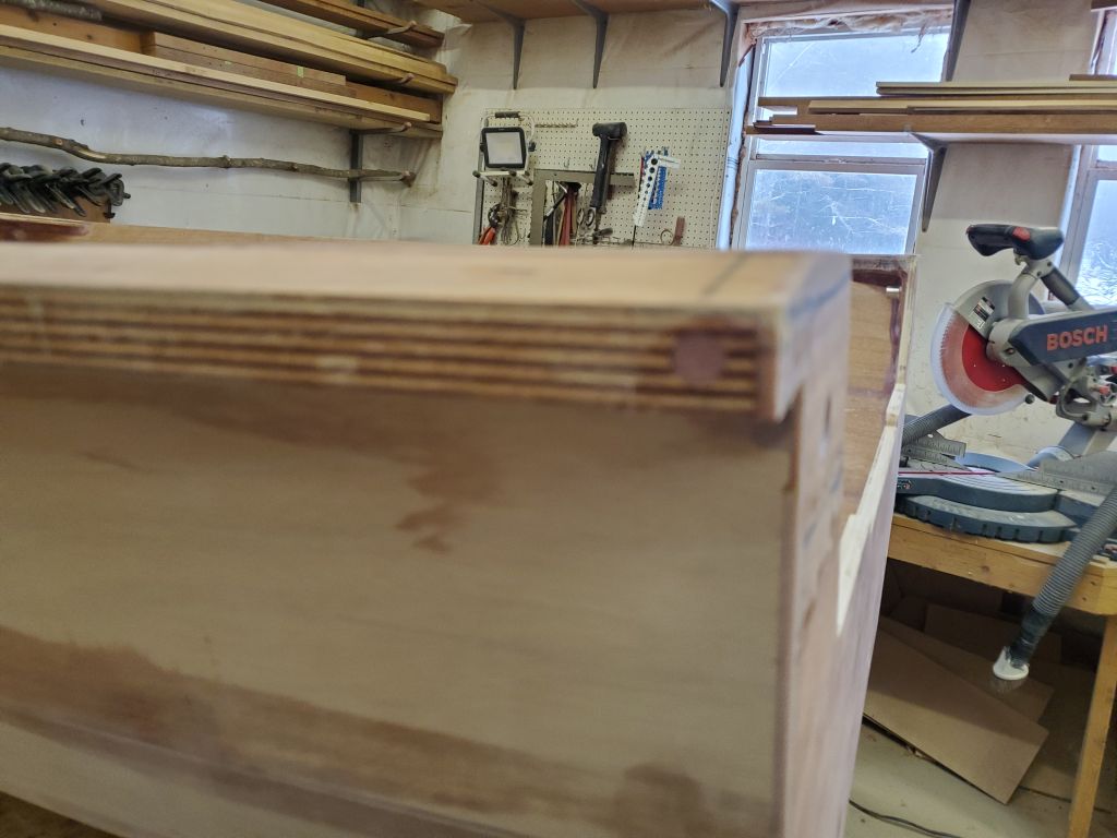
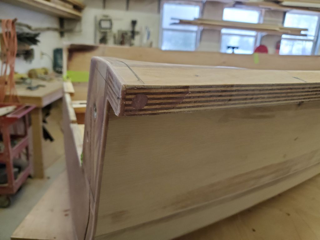
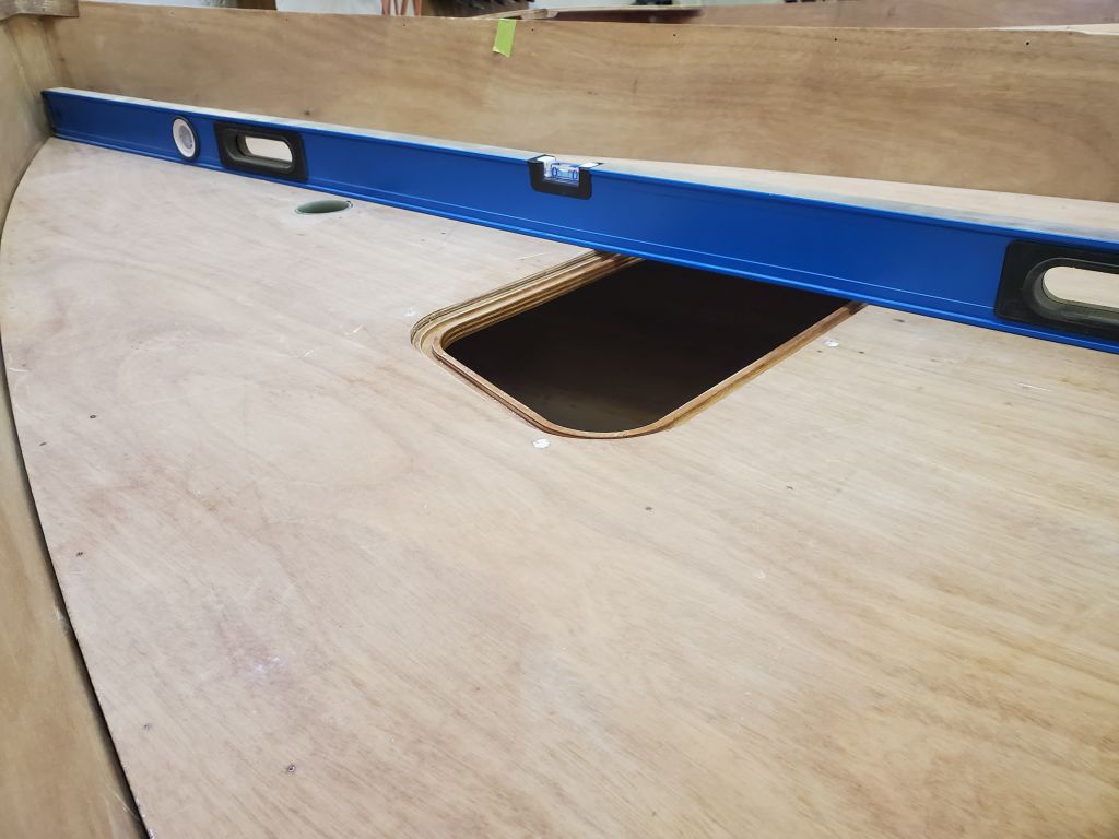
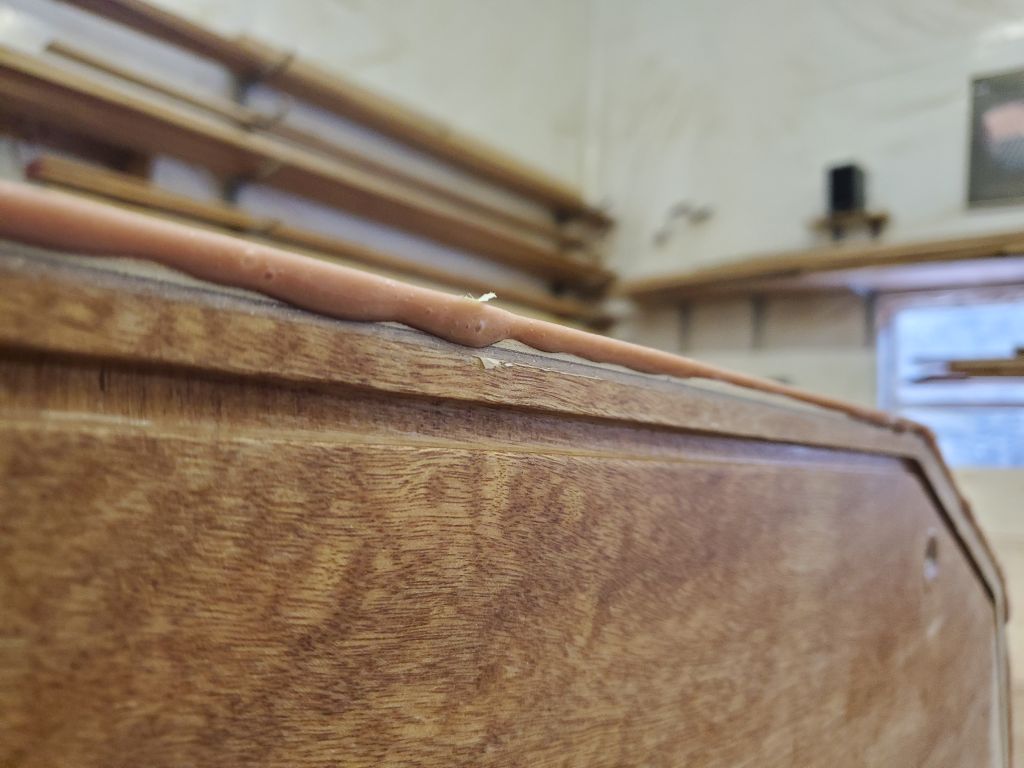
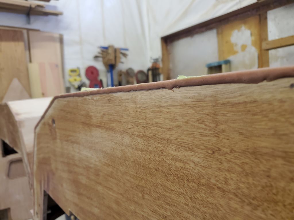
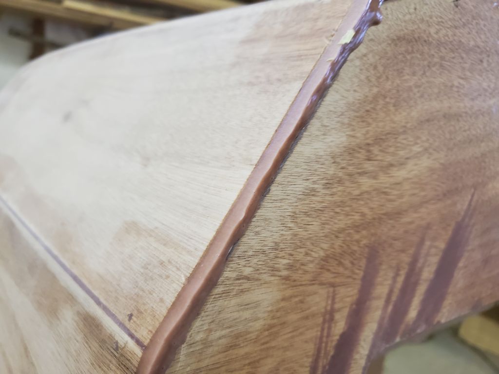
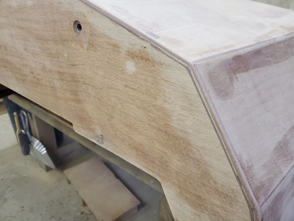
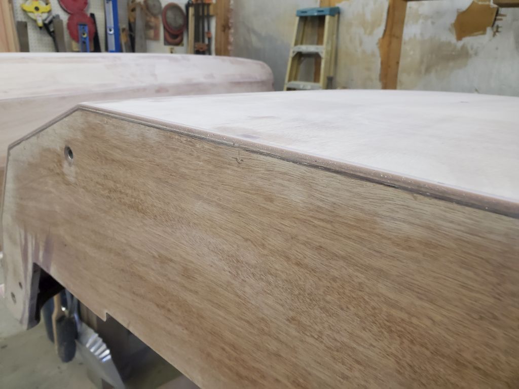
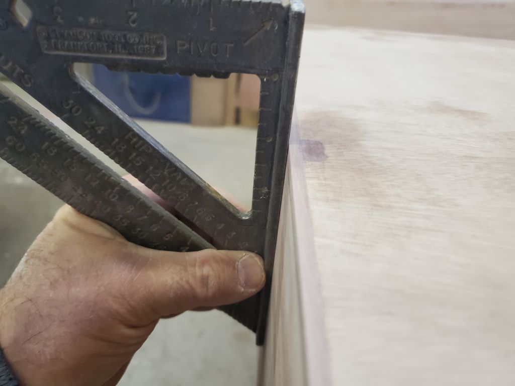
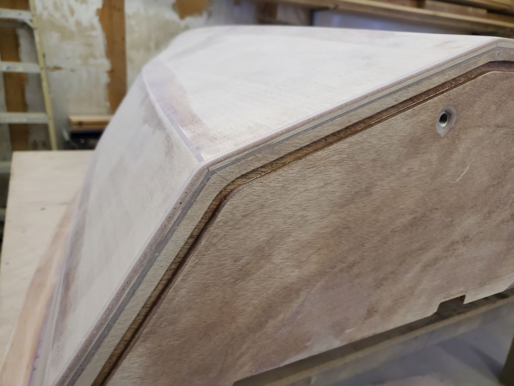
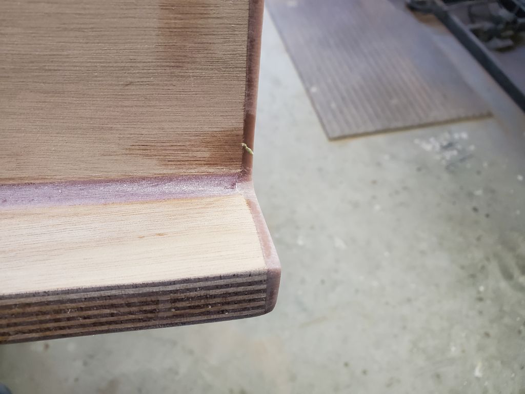
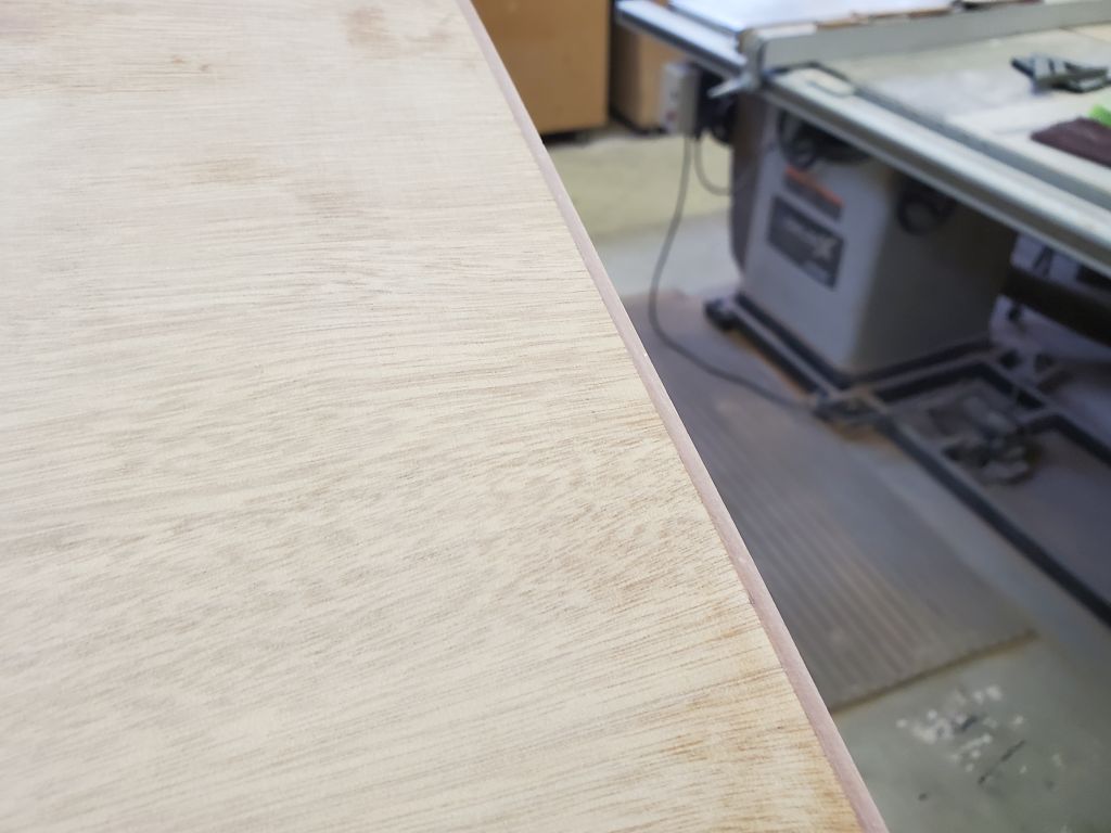
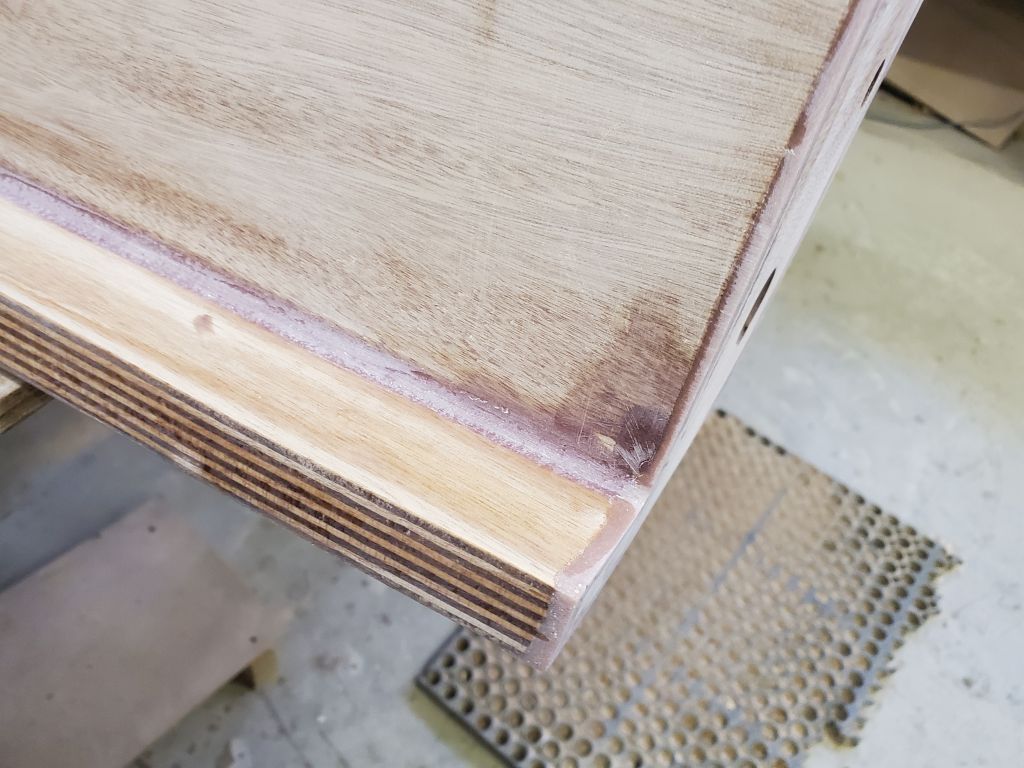
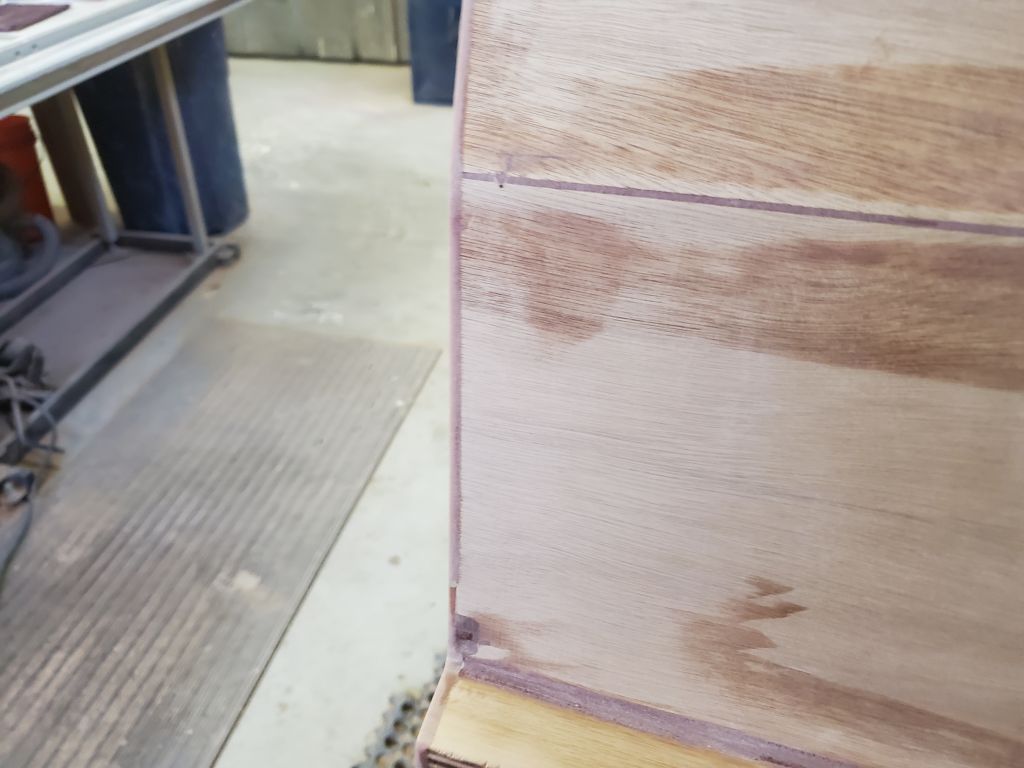
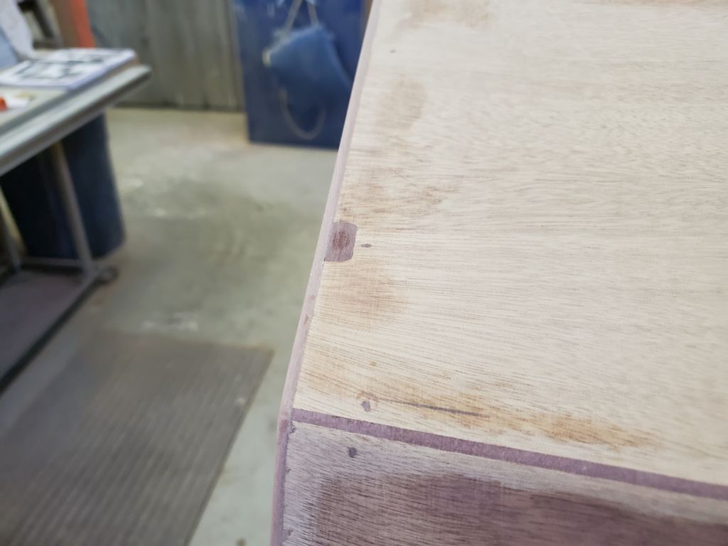
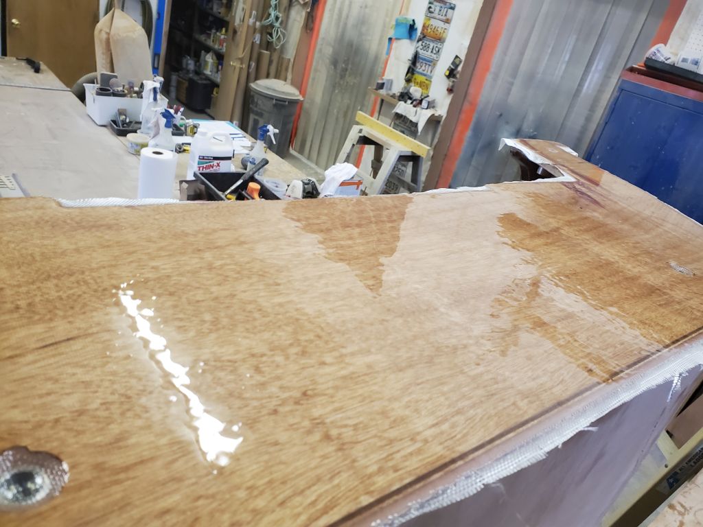
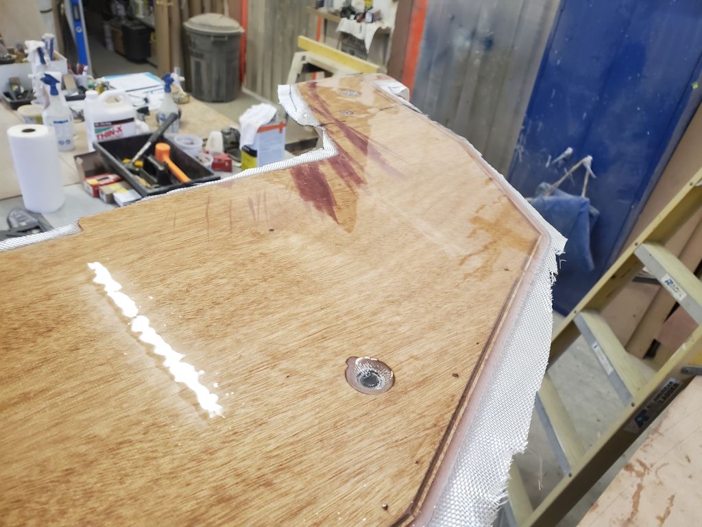
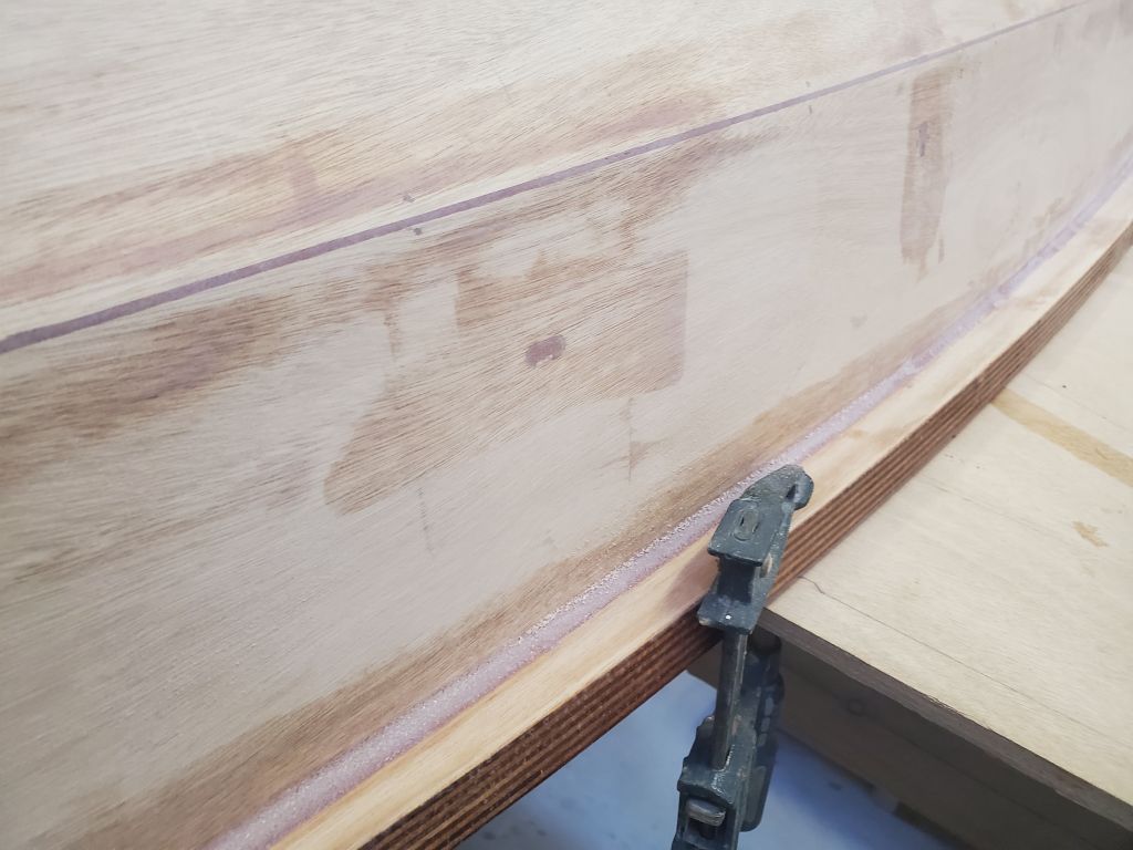
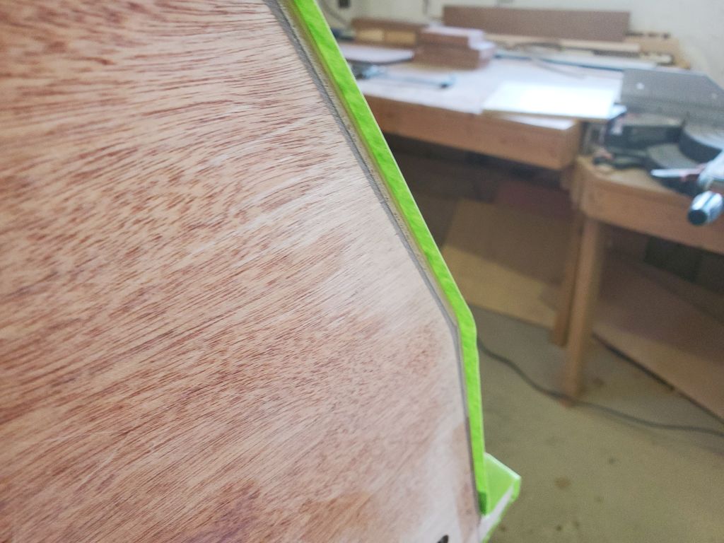
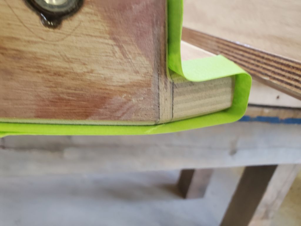
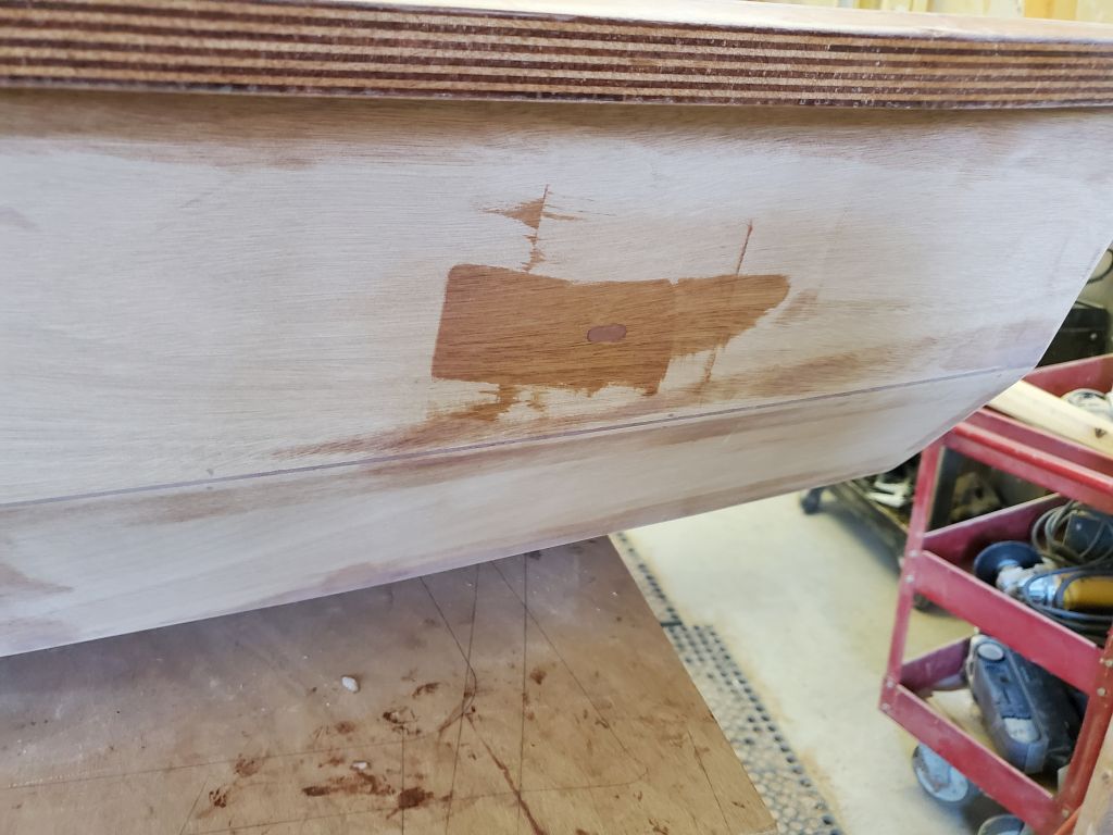
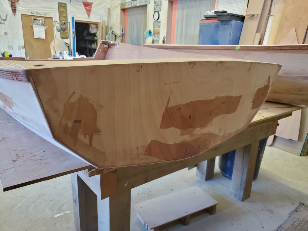
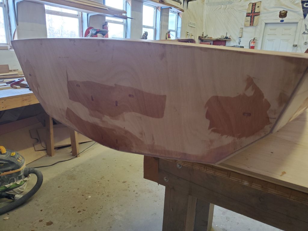
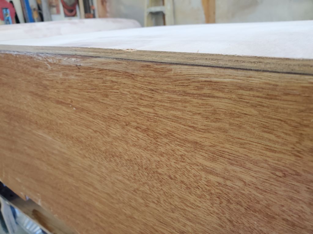
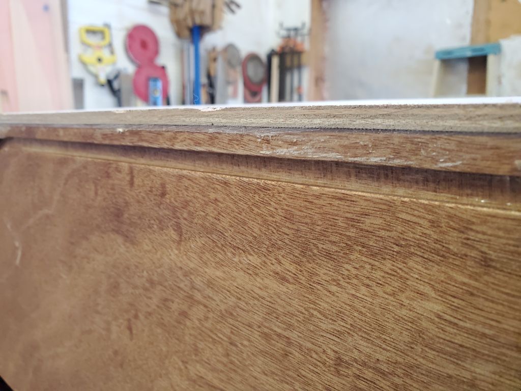
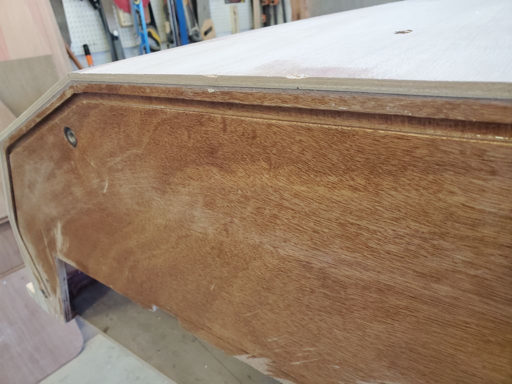
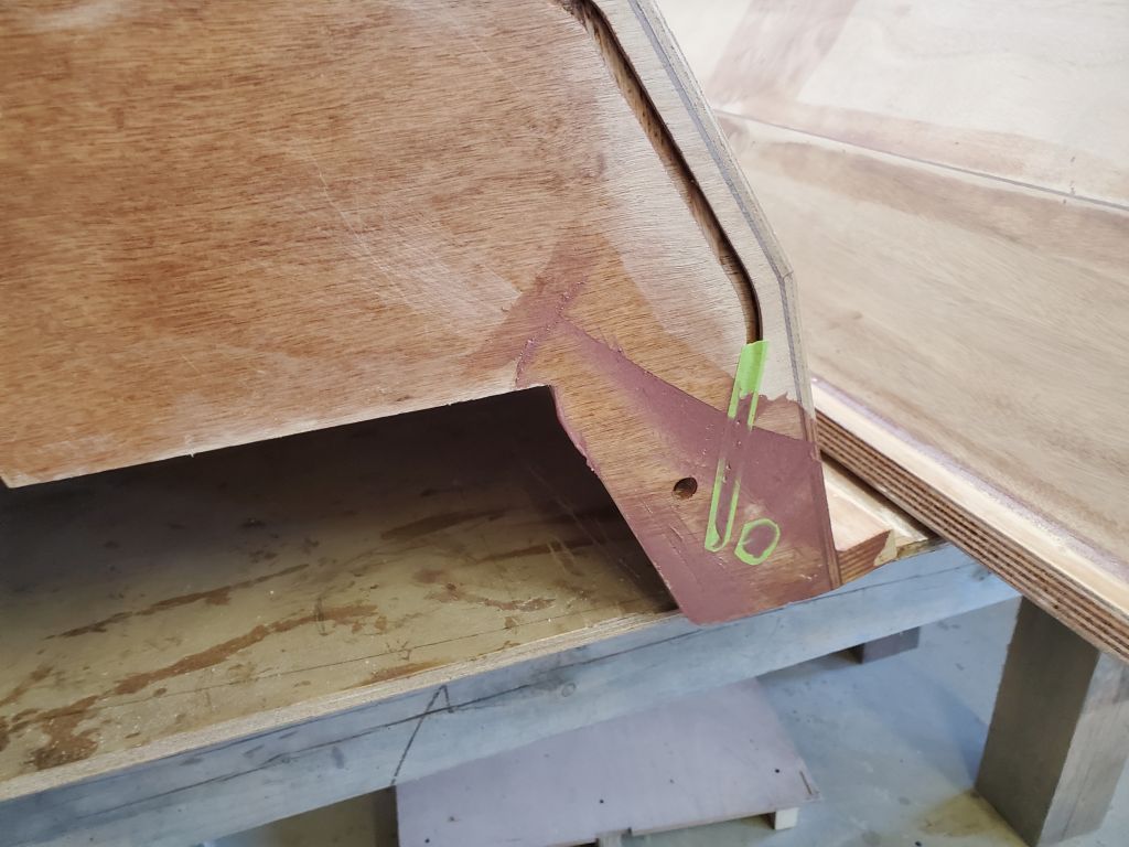
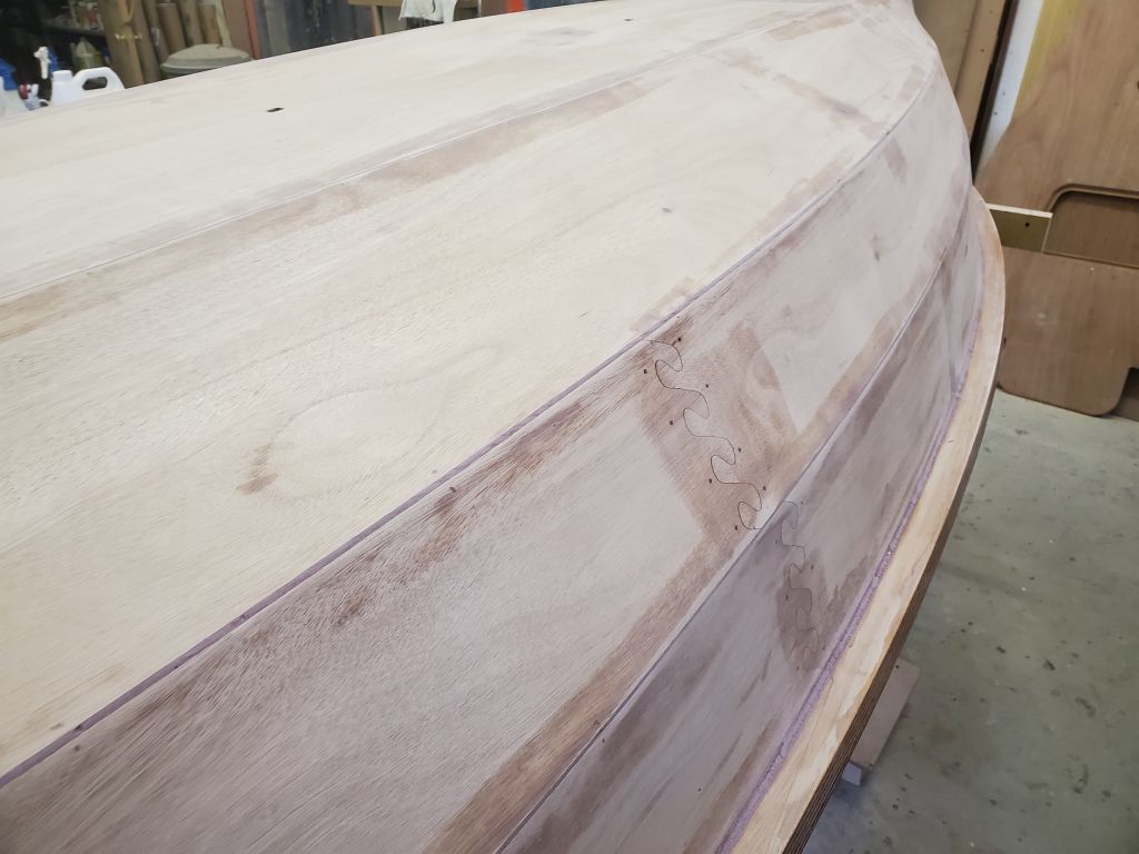
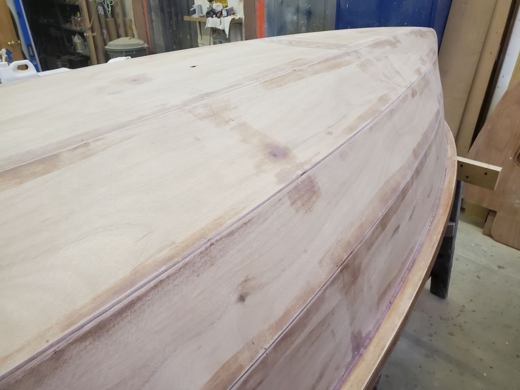
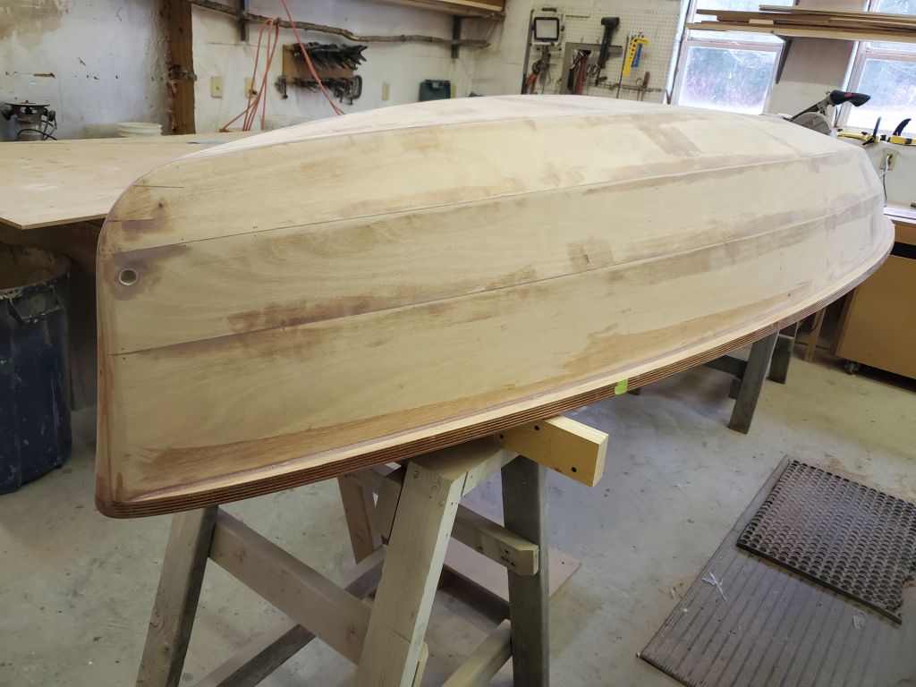
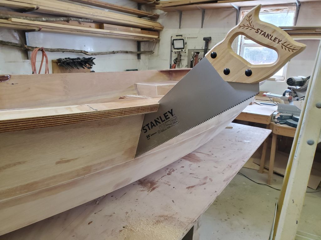
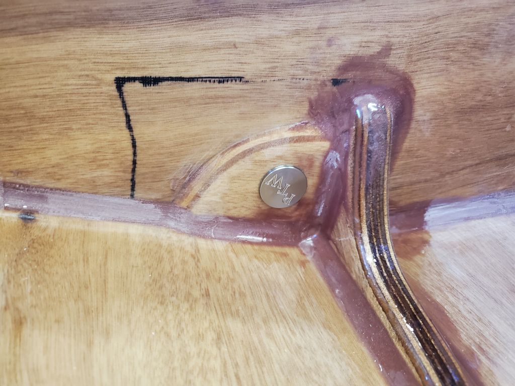
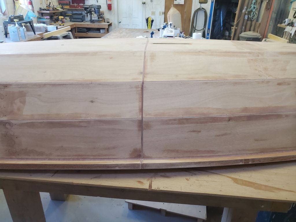
The seam was tight and mostly flush, and required only the lightest of touch-ups with a sanding block to ensure it was straight and fair across. I finished off the hull prep by dressing up the remains of the hull by hand and as needed; because I’d done all the hull fairing and filling work much earlier, and incrementally as needed, this step didn’t require a lot of time or effort now. I vacuumed and cleaned the hull, and separated the halves once more so I could set them up on the bench for fiberglassing.
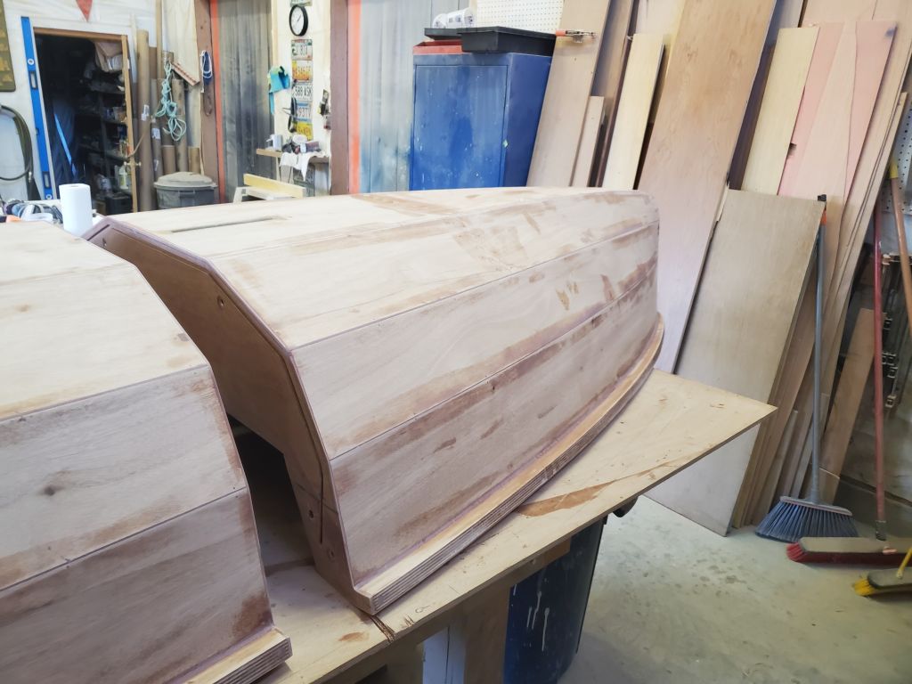
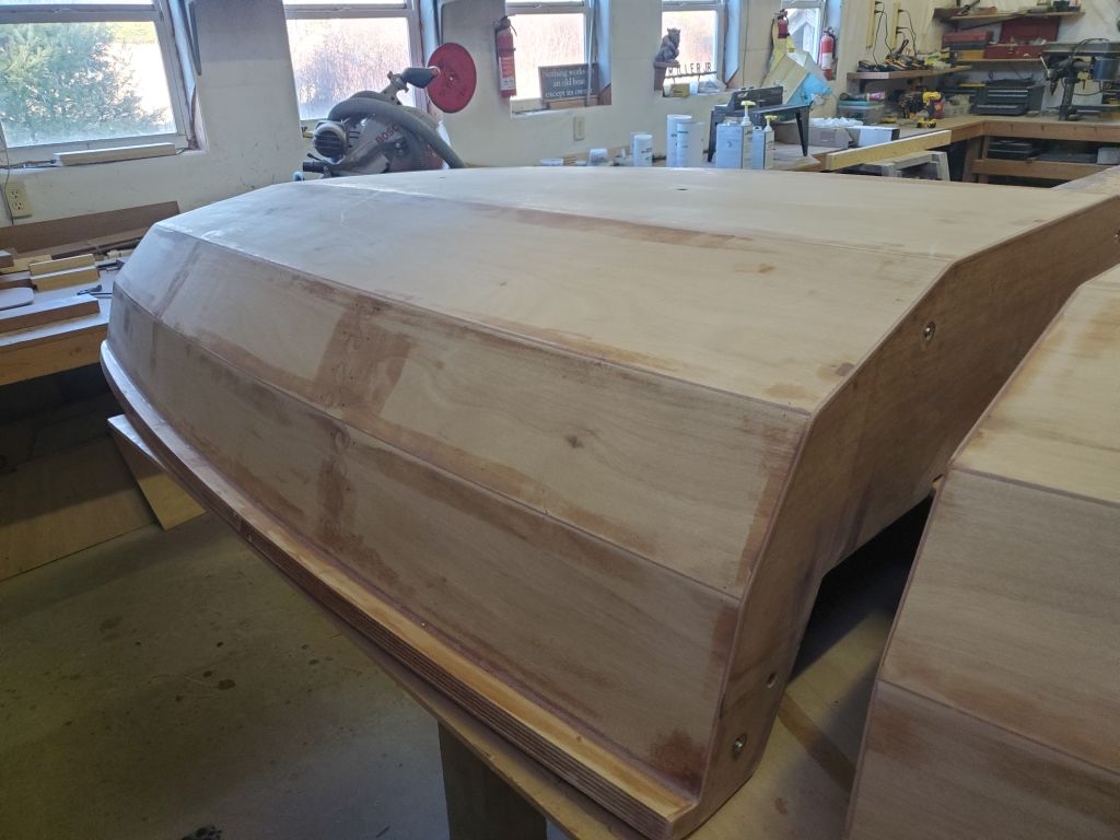
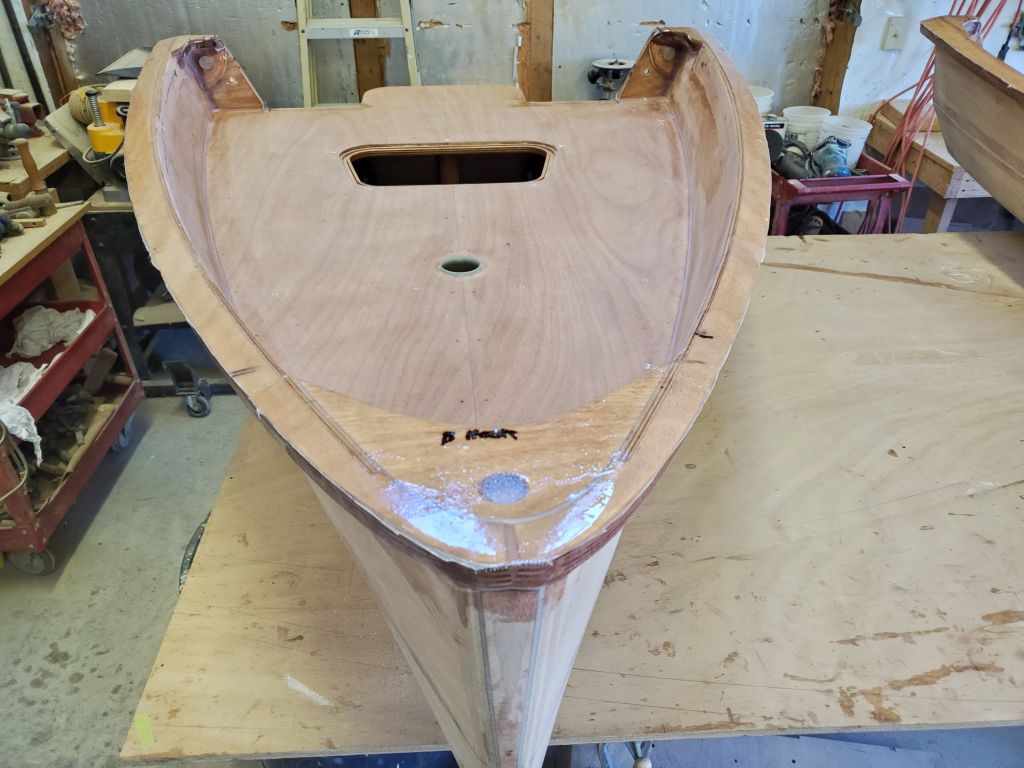
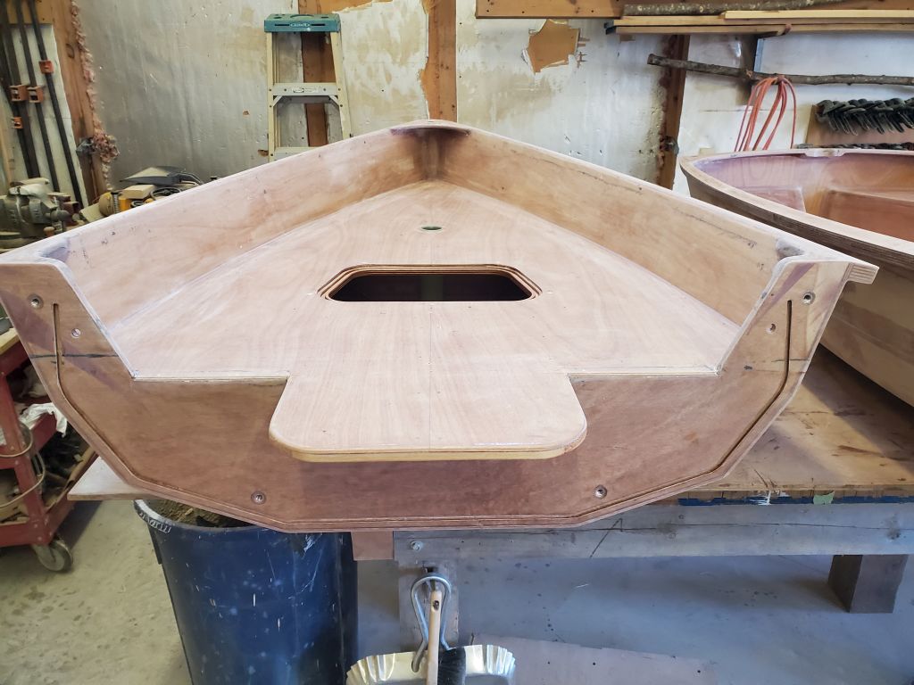
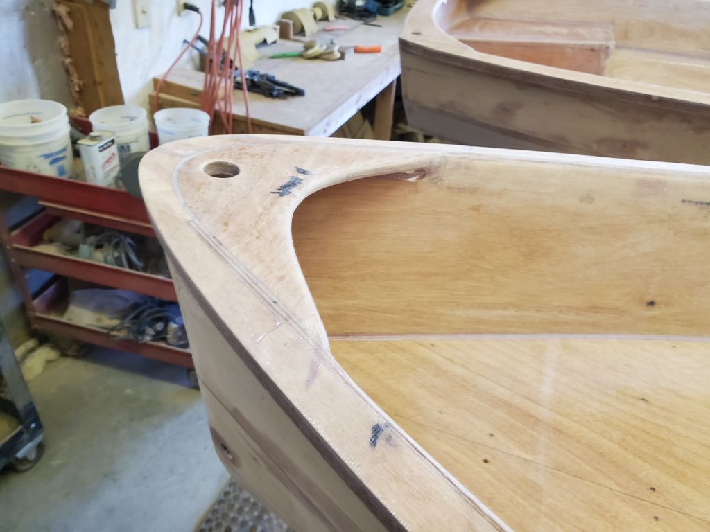
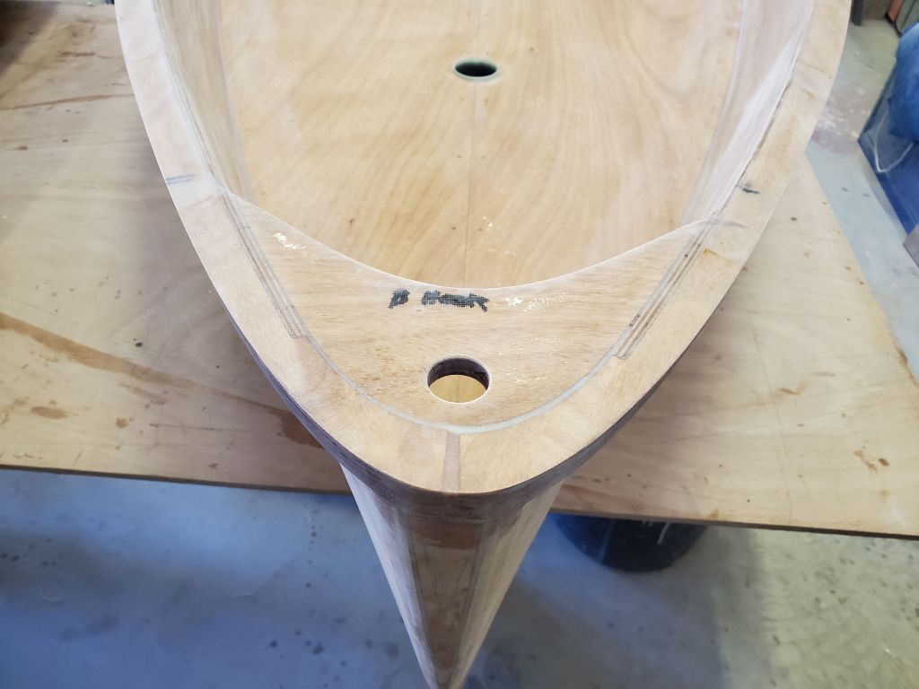
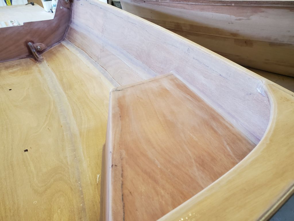
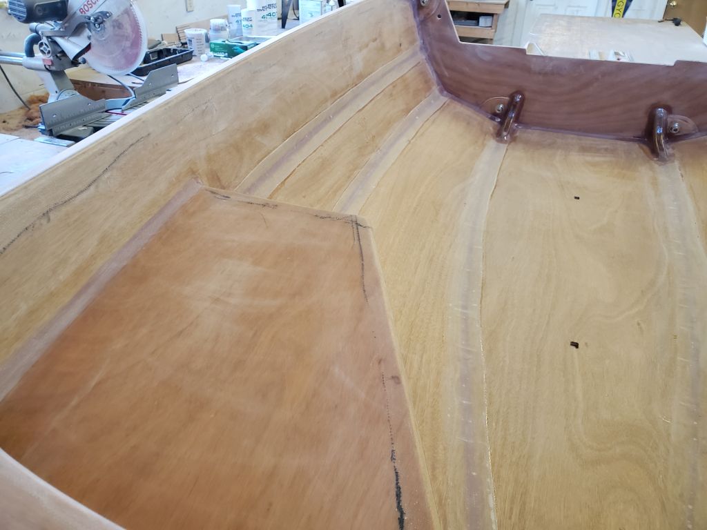
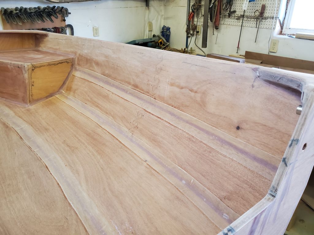
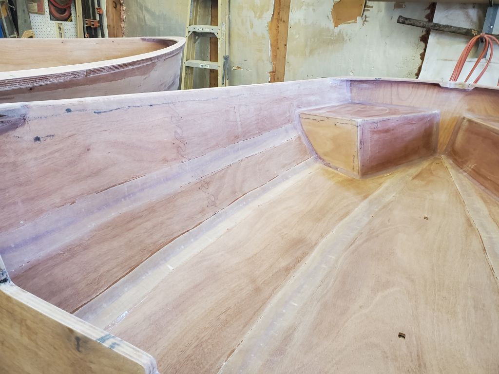
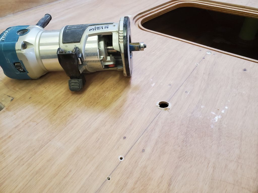
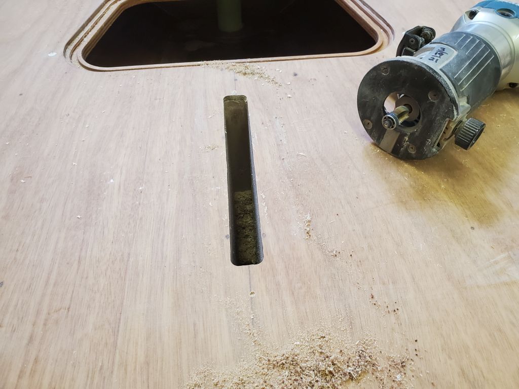
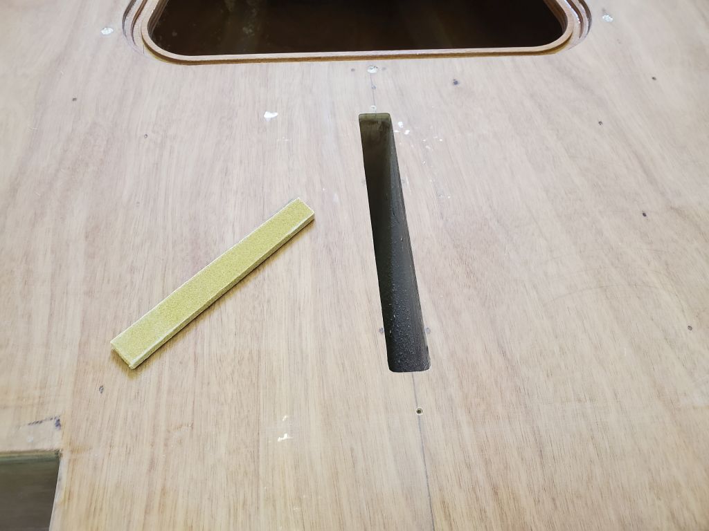
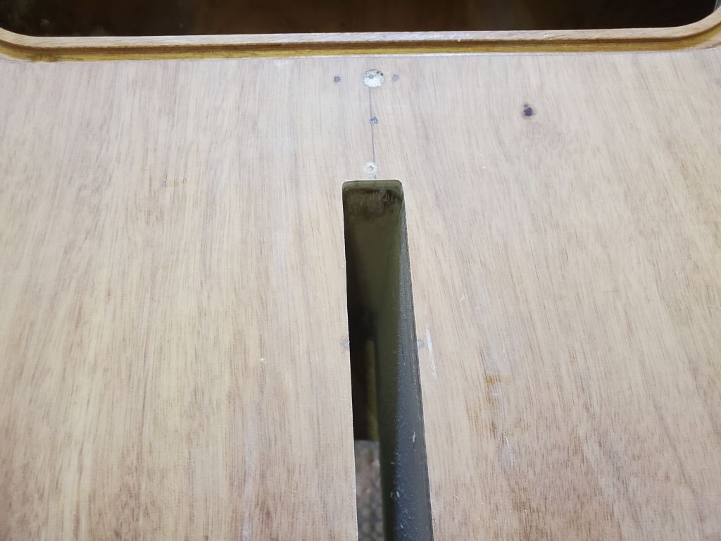
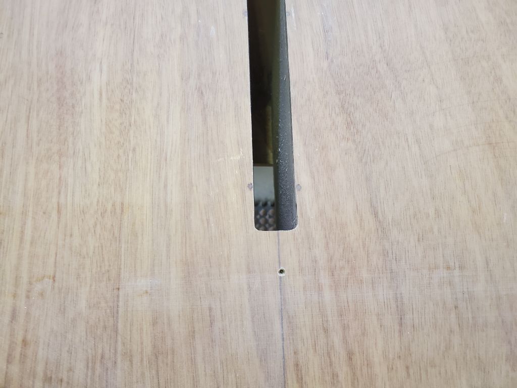
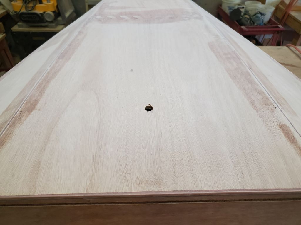
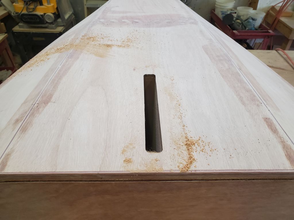
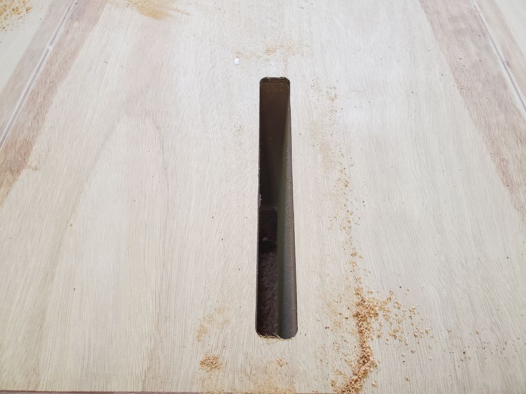
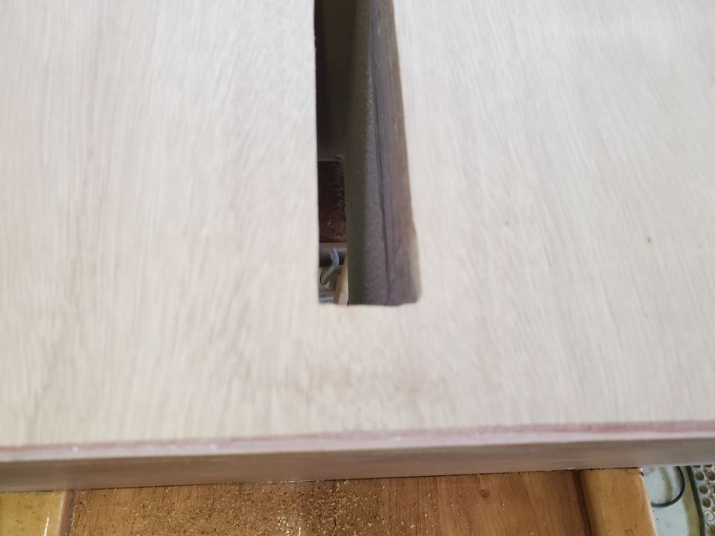
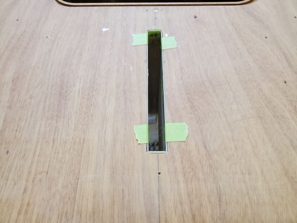
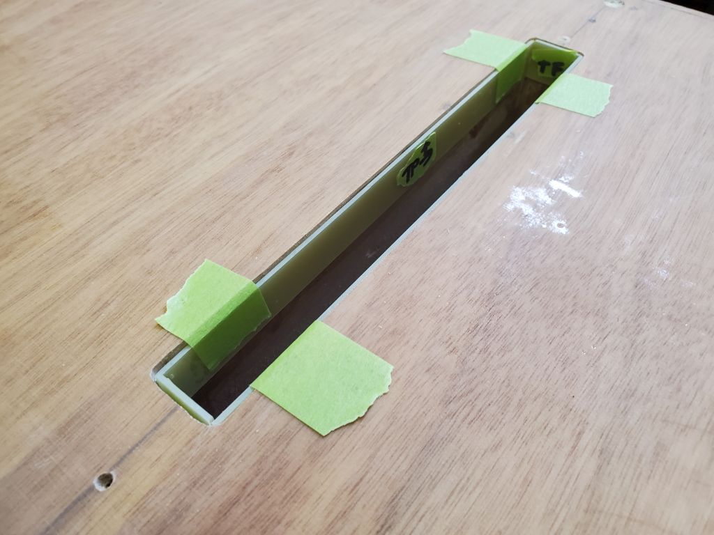
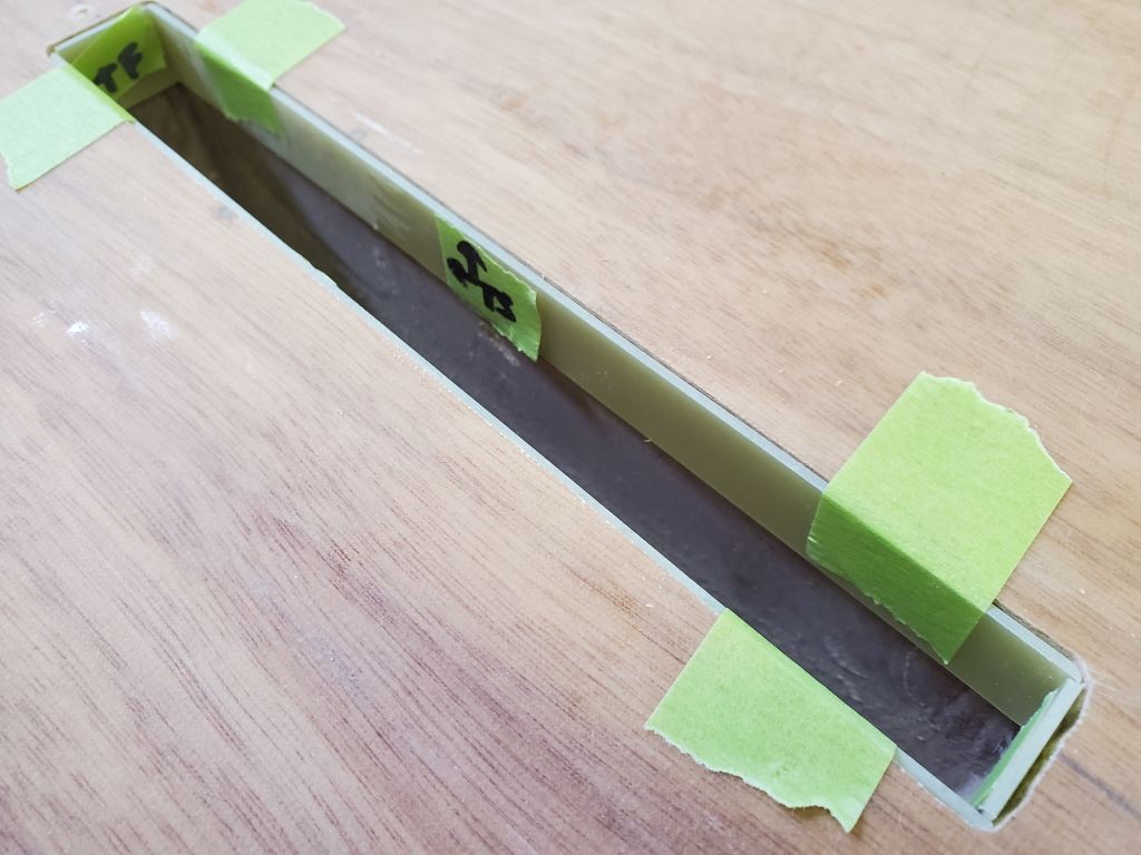
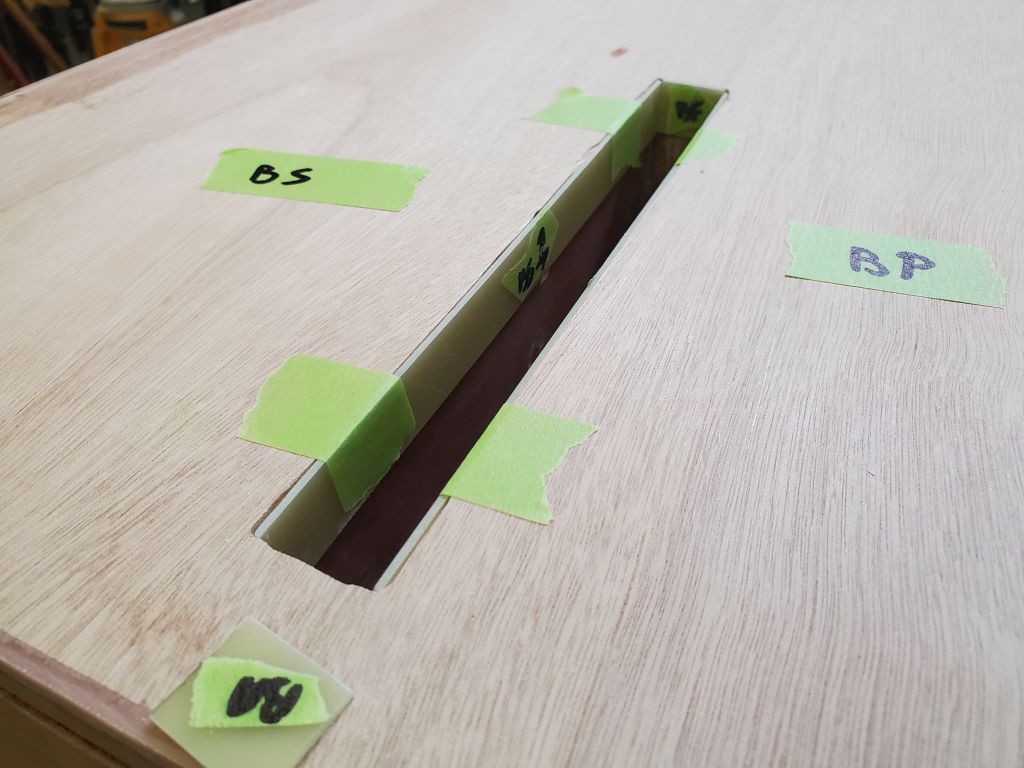
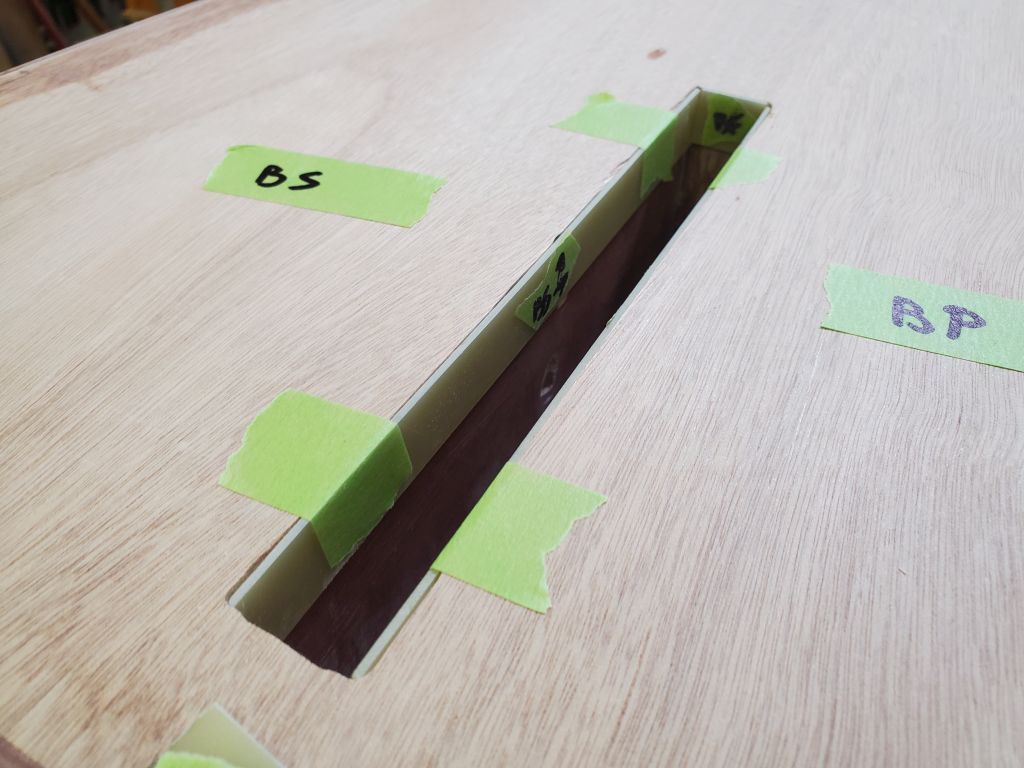
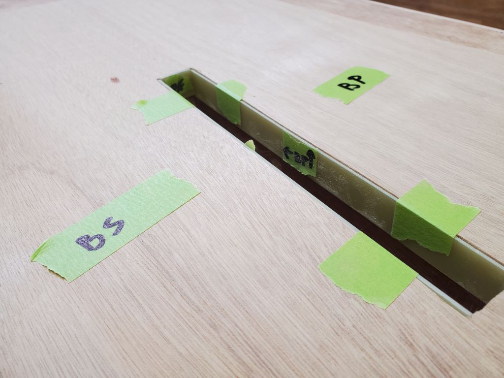
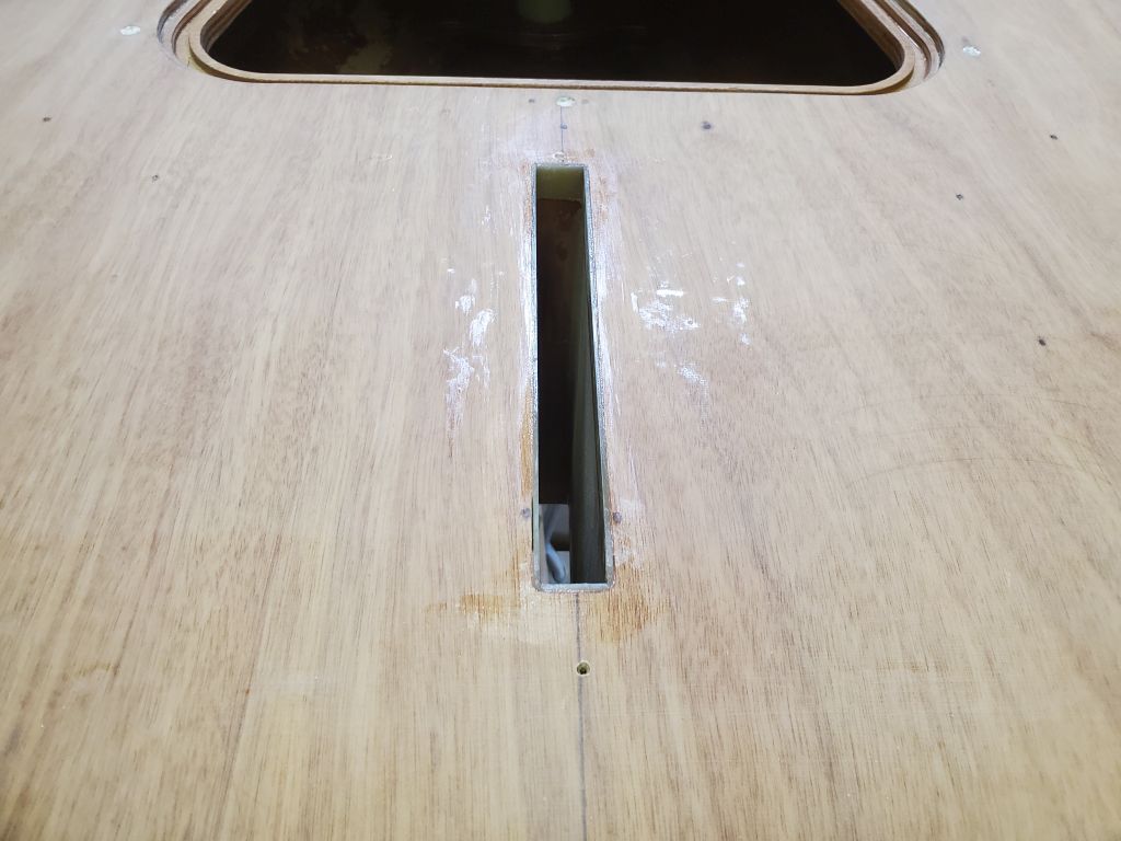
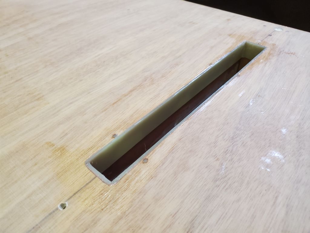
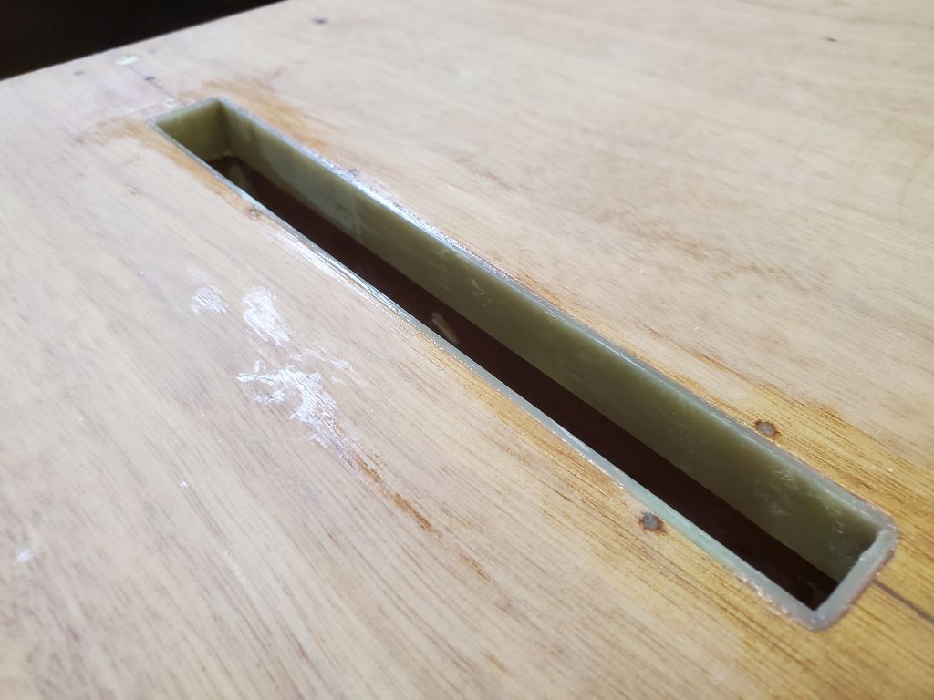
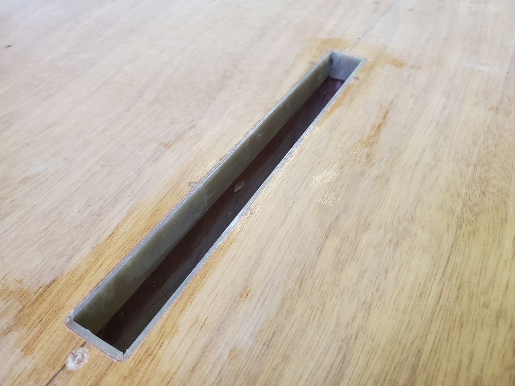
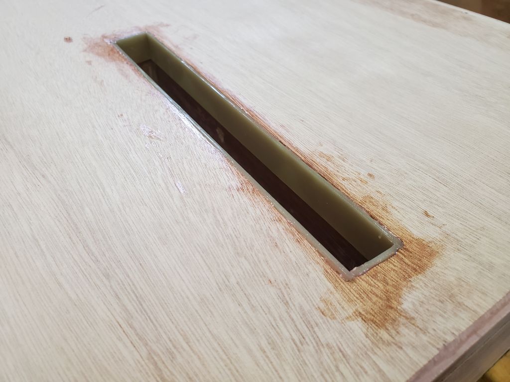
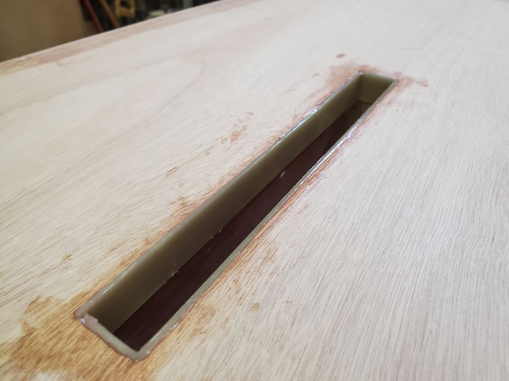
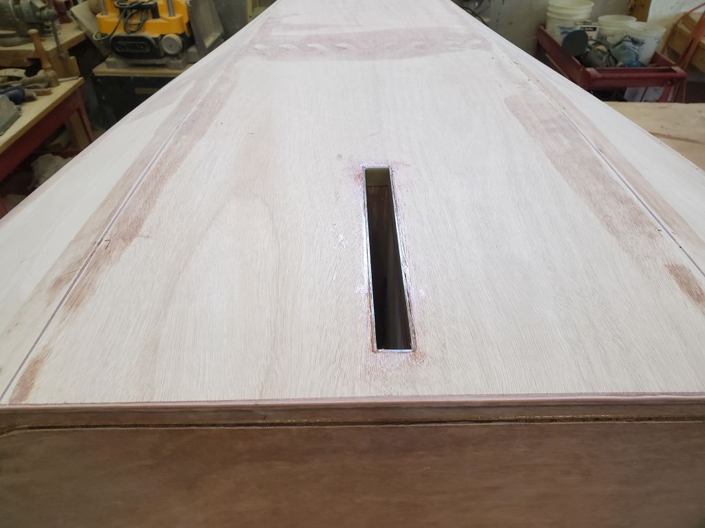
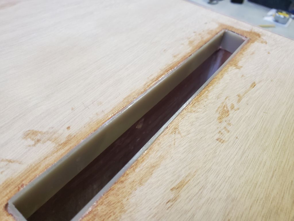
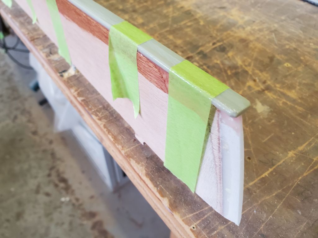
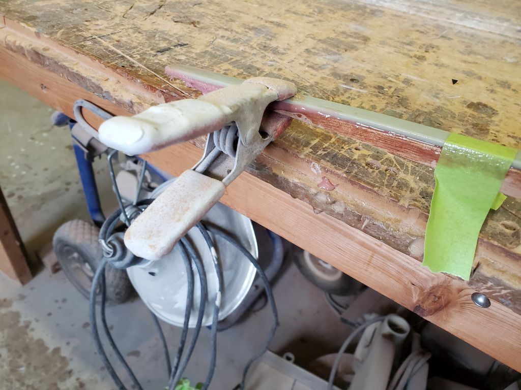
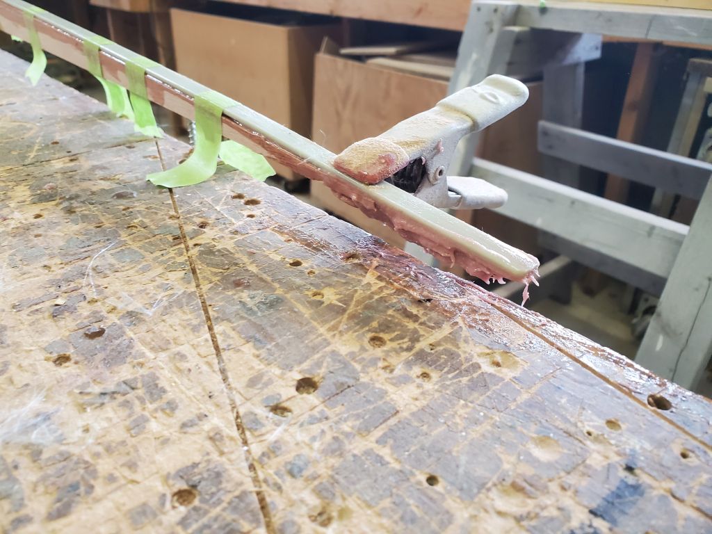
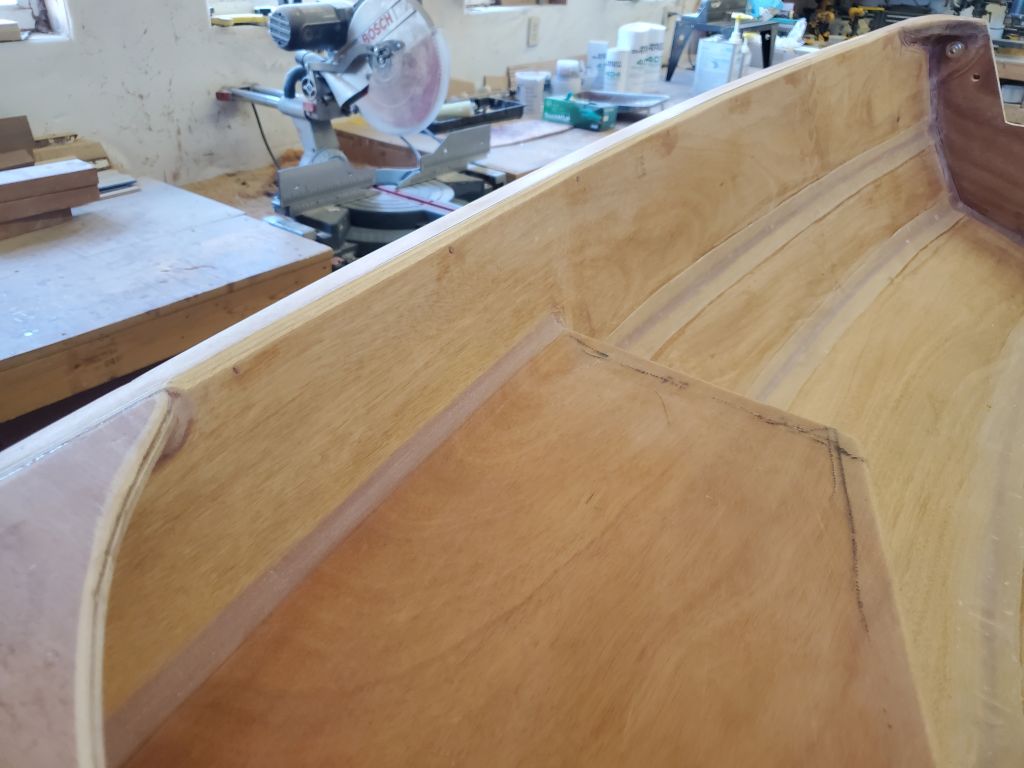
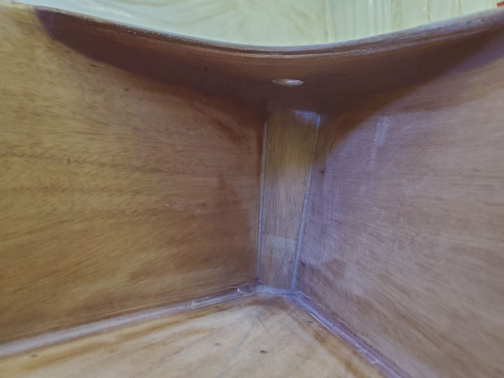
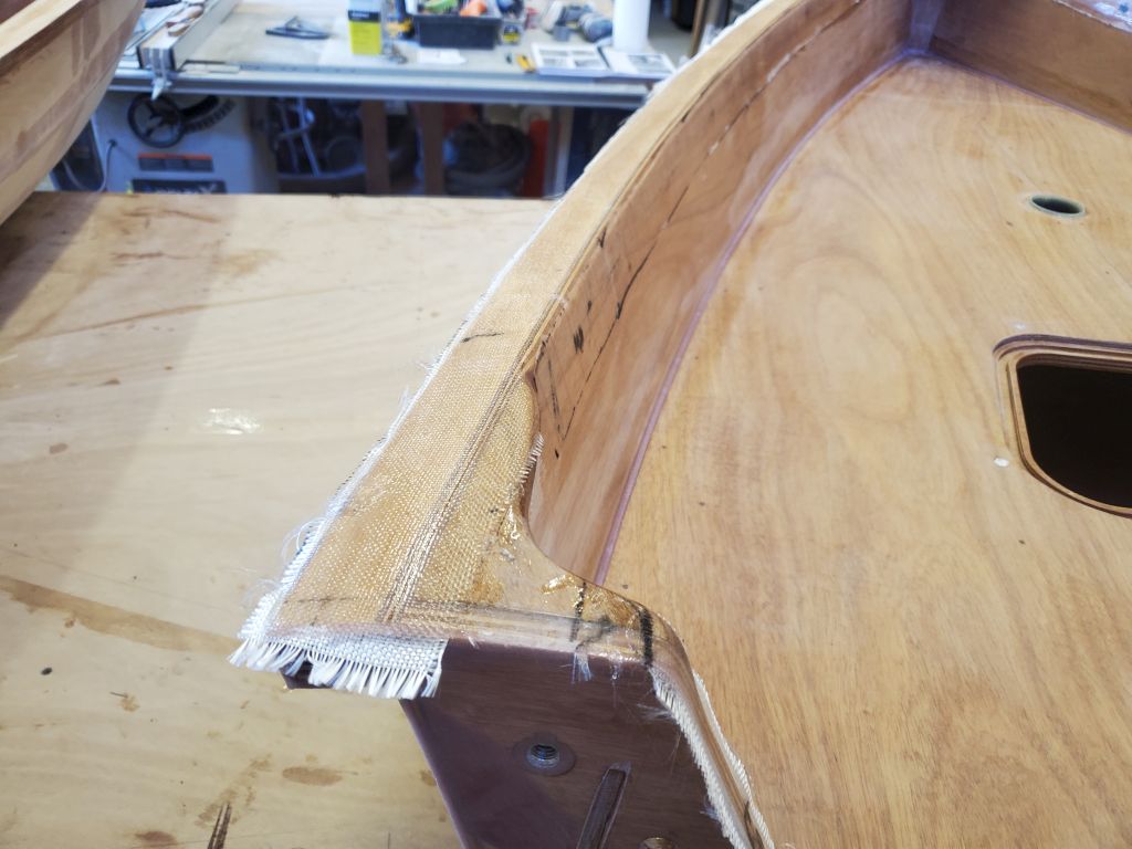
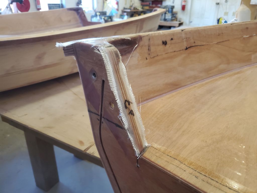
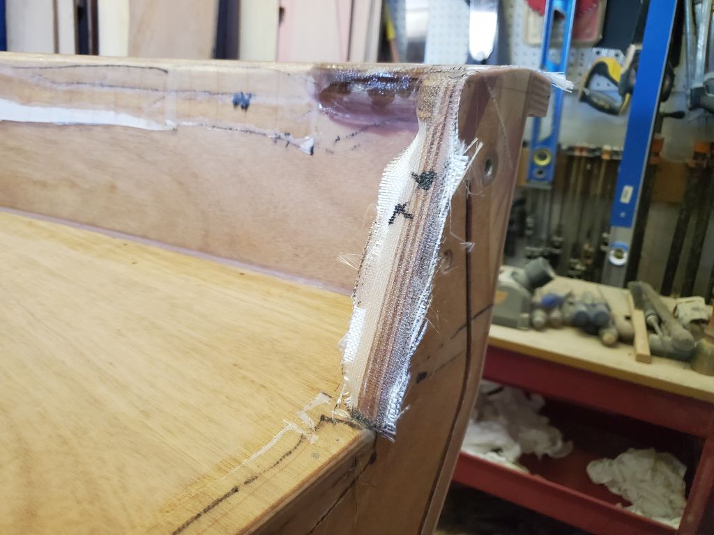
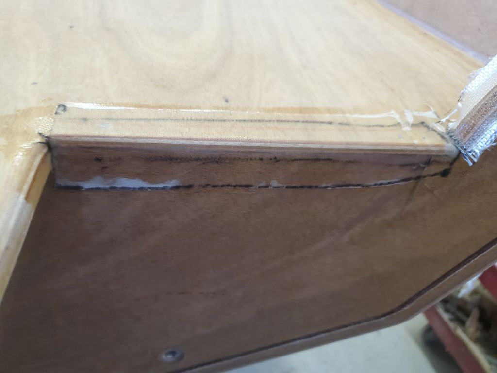
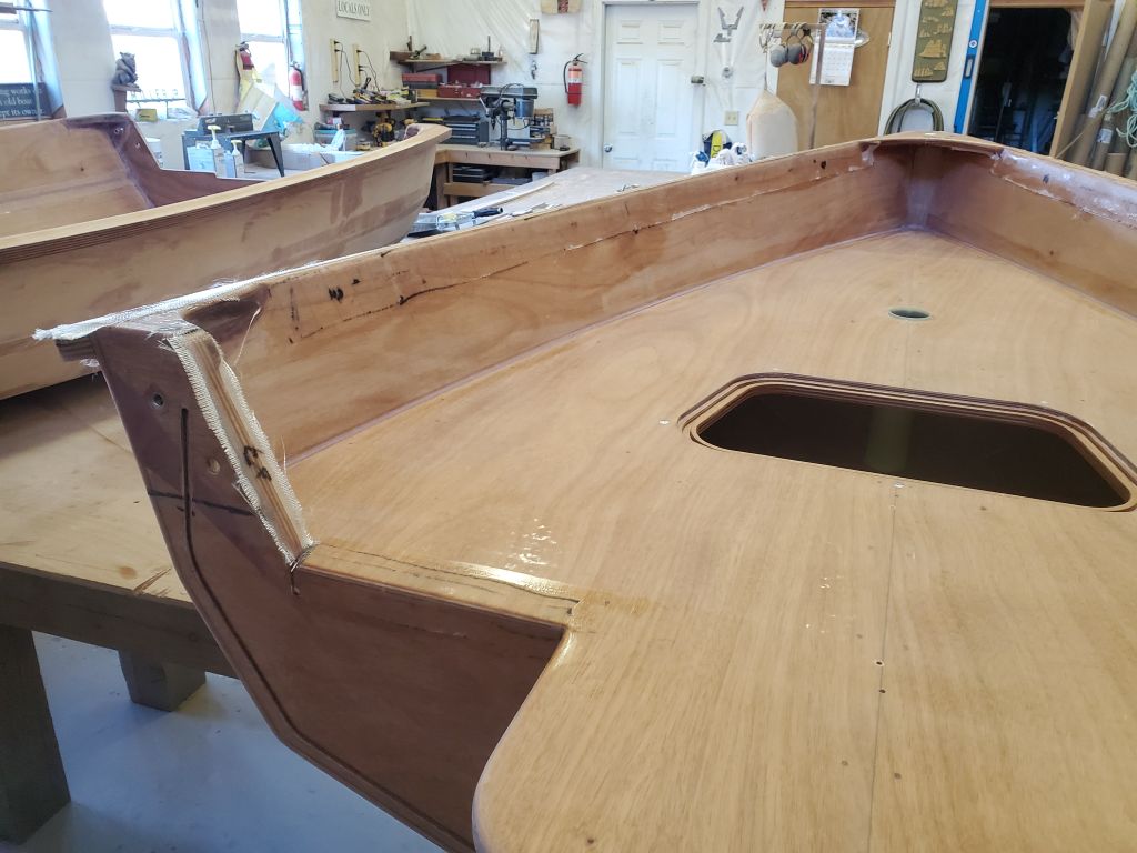
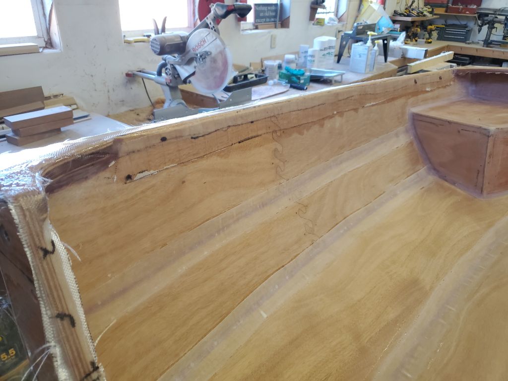
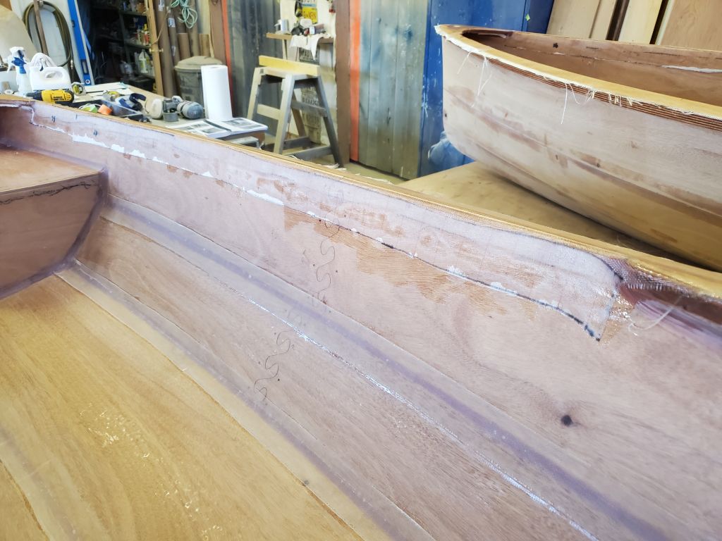
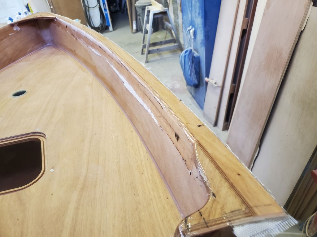
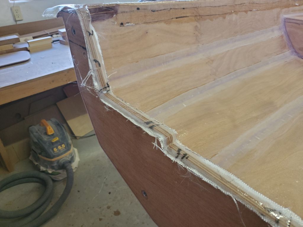
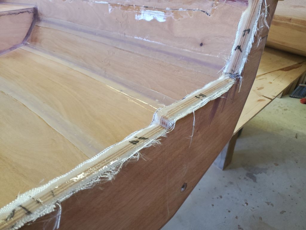
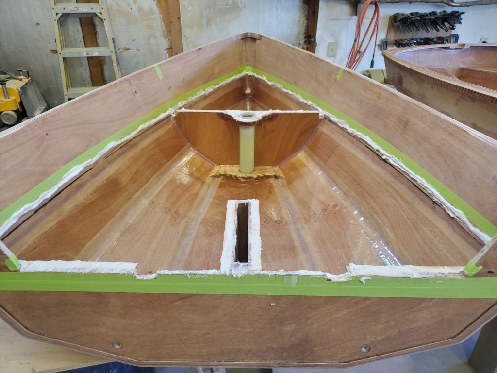
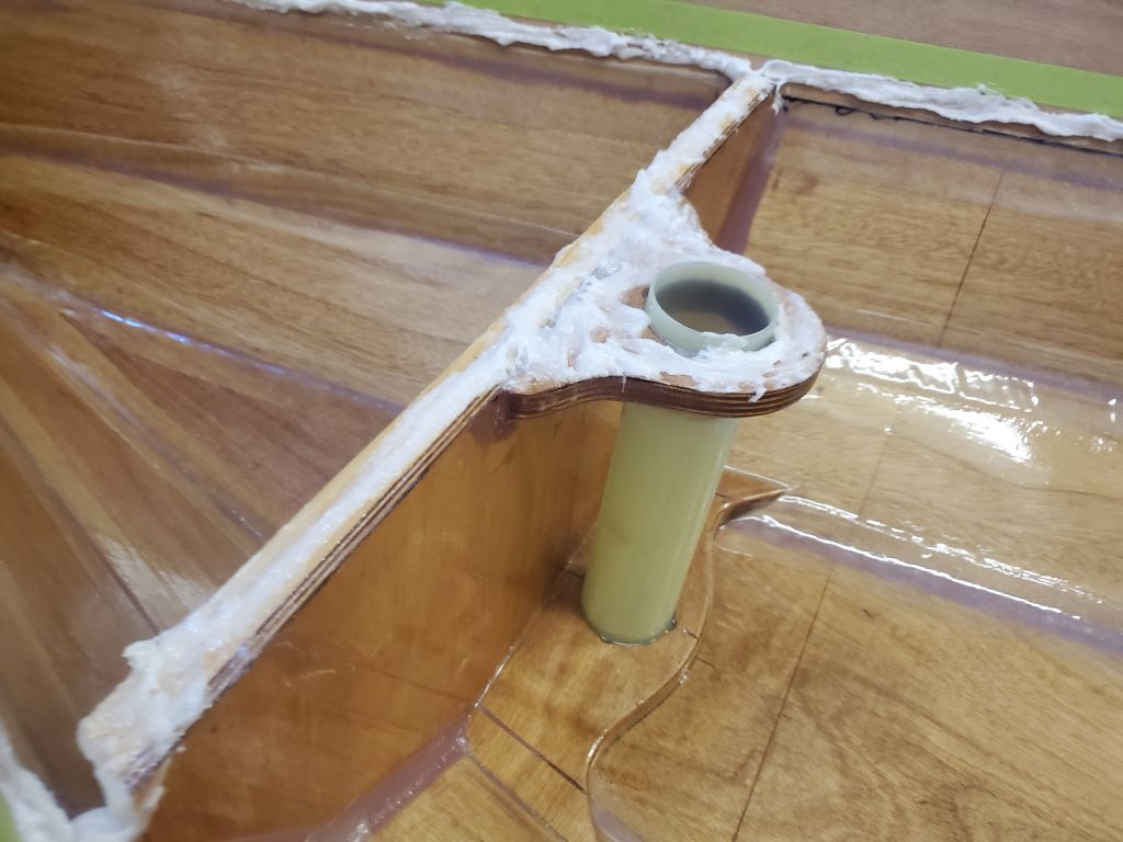
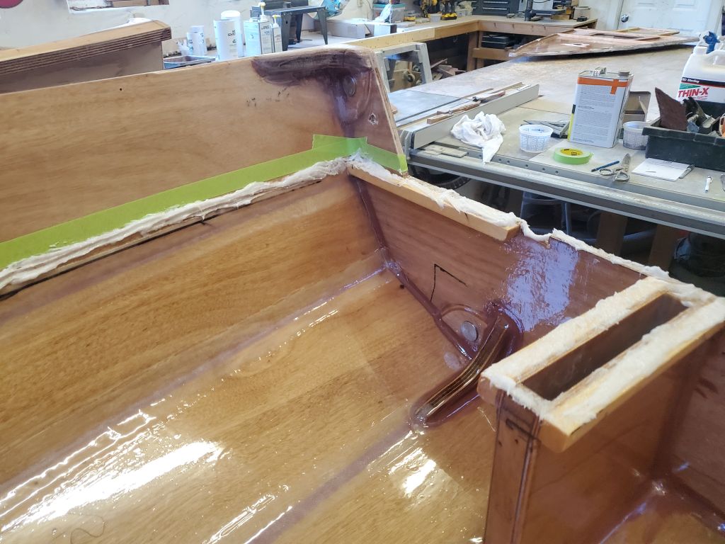
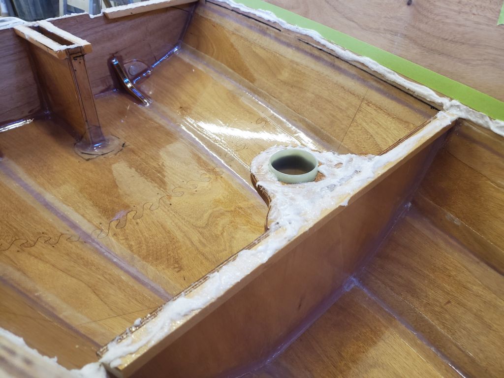
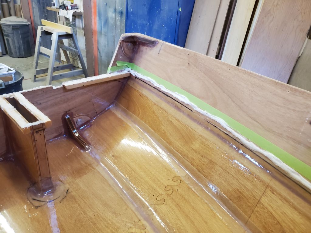
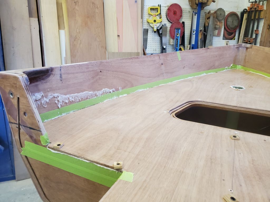
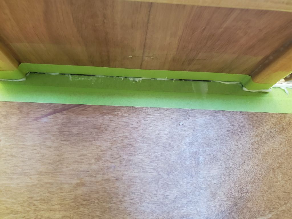
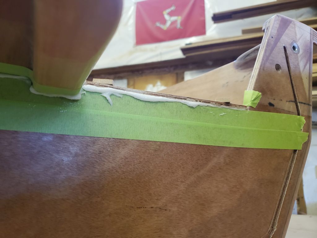
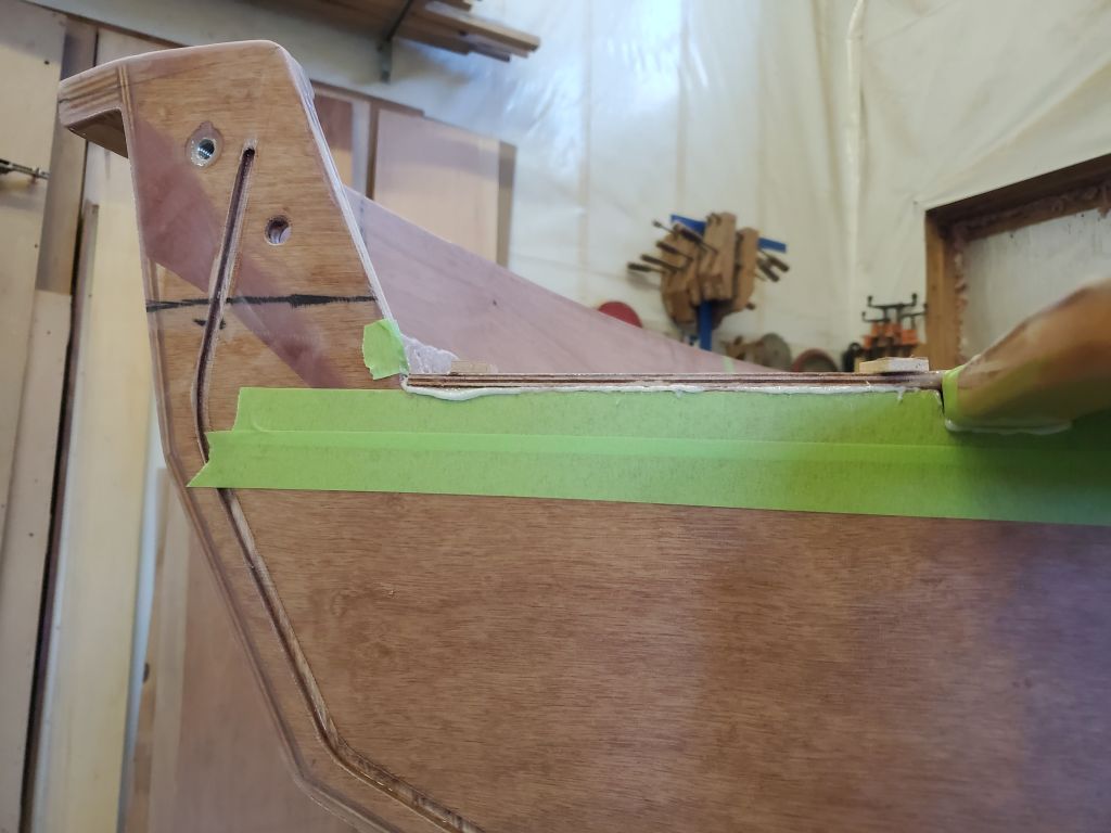
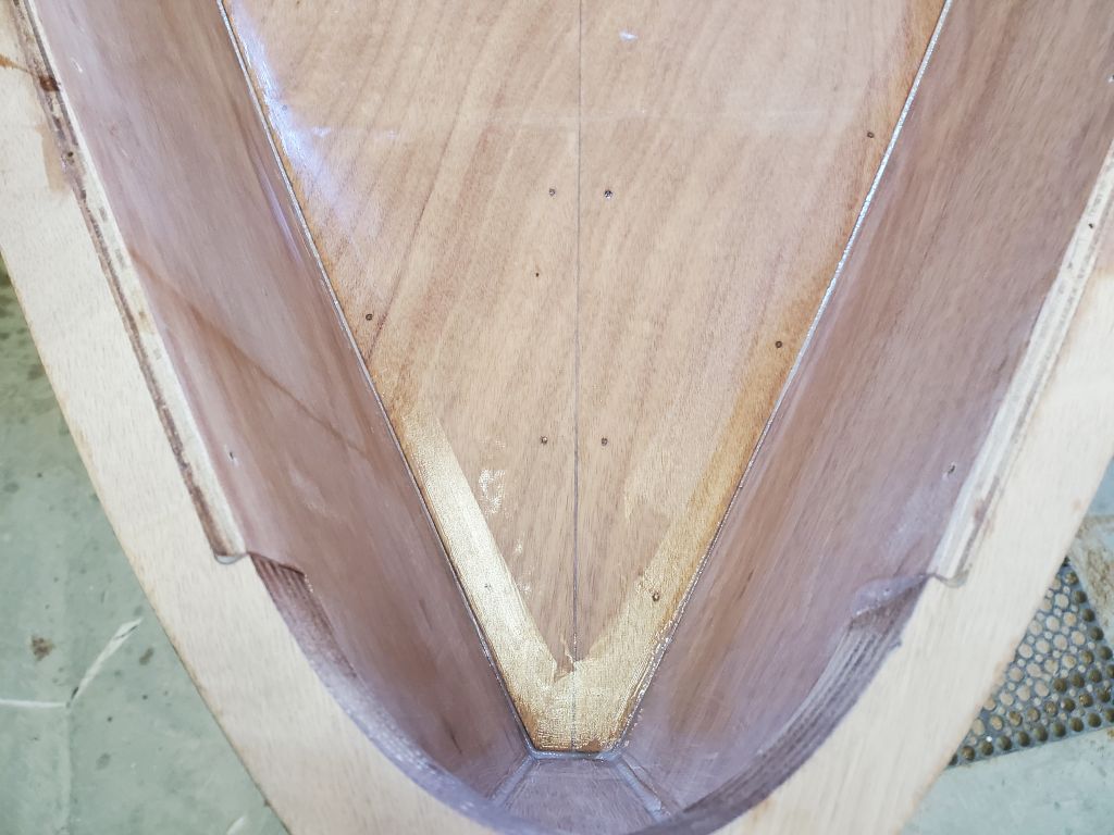
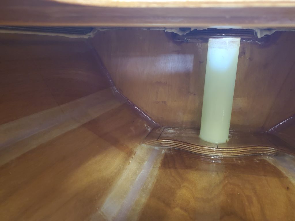
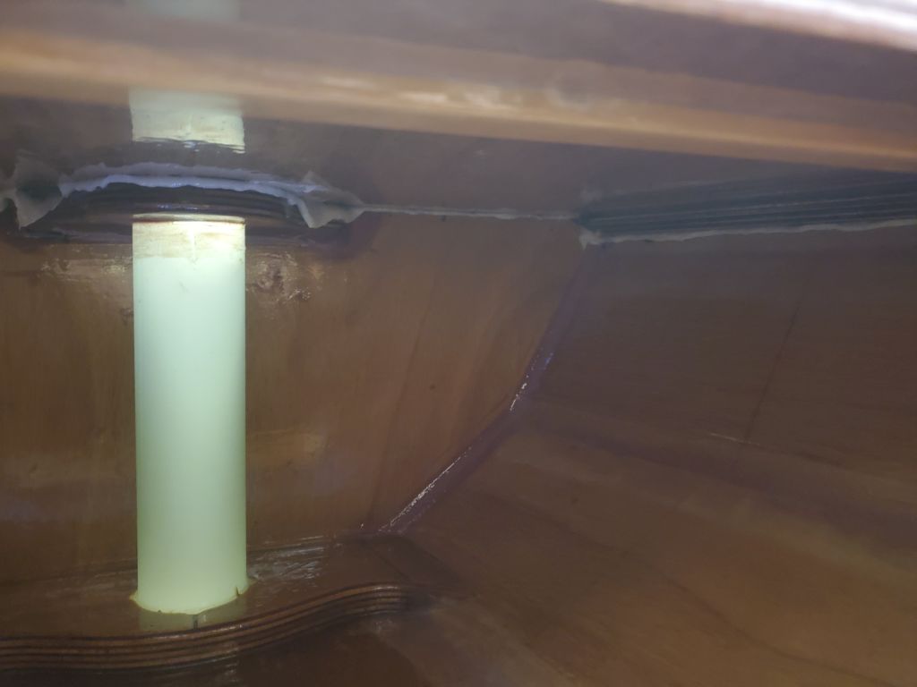
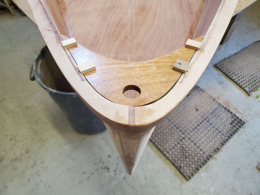
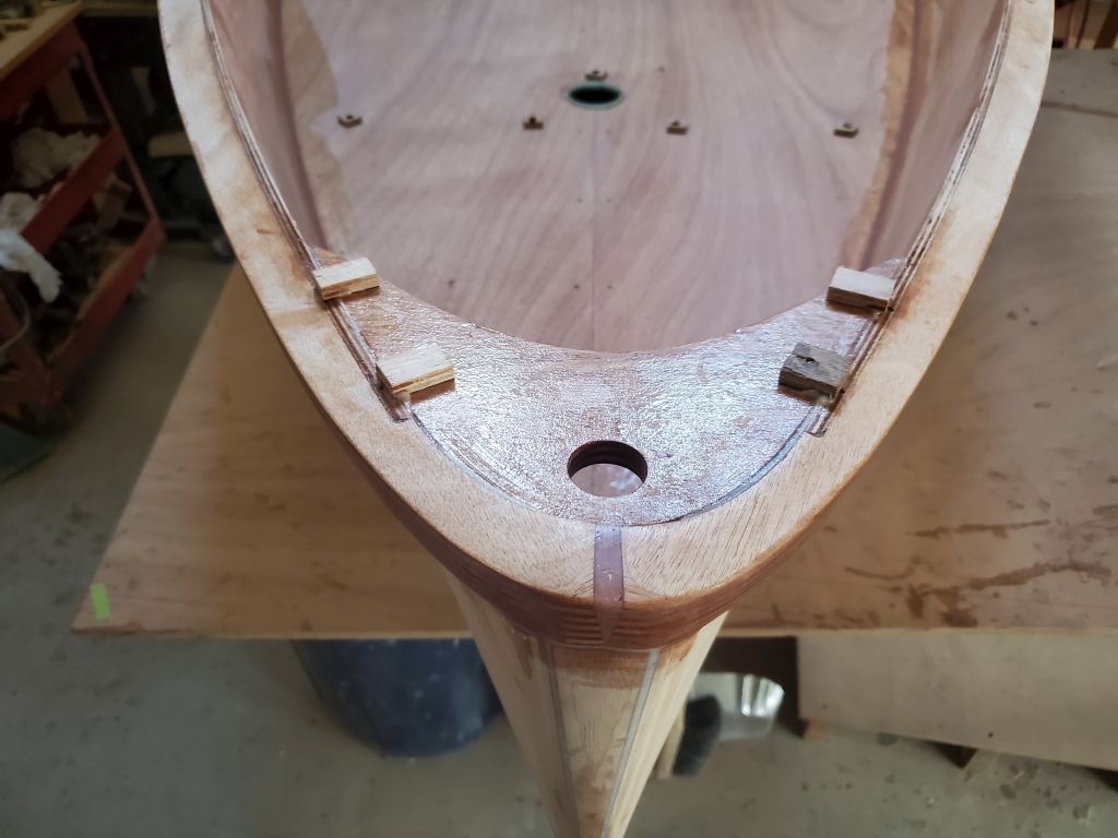
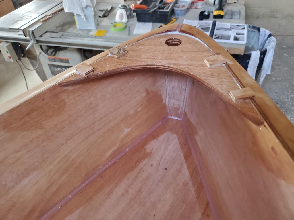
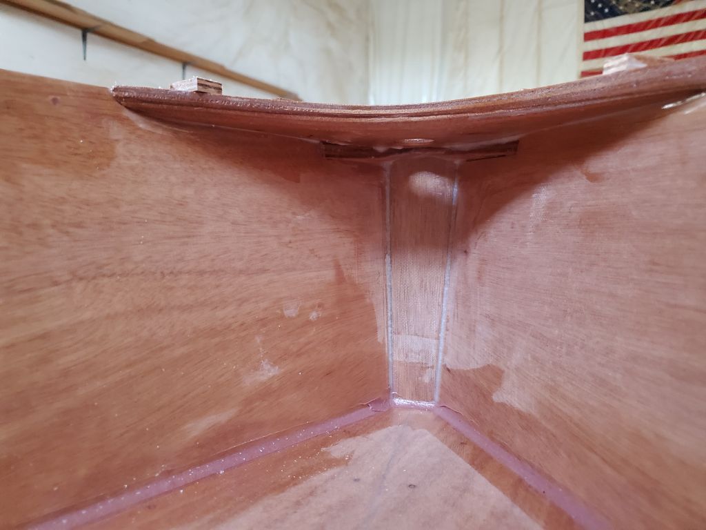
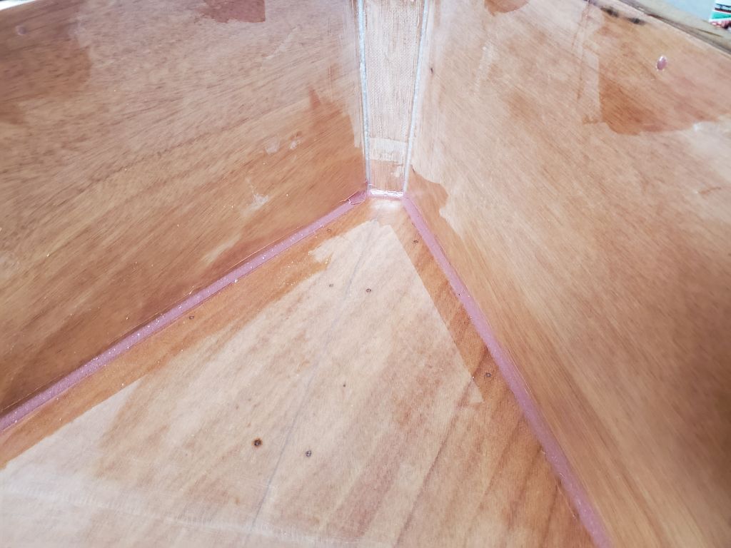
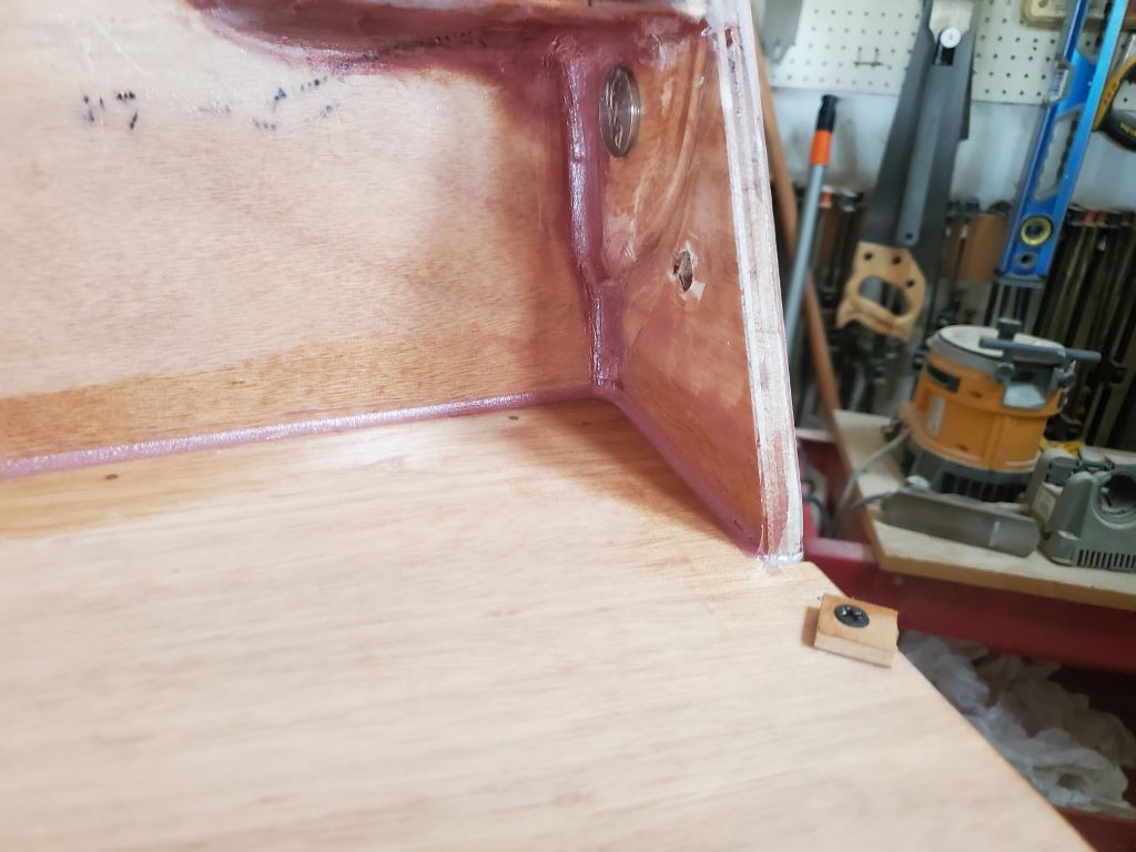
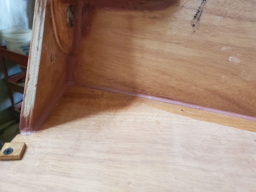
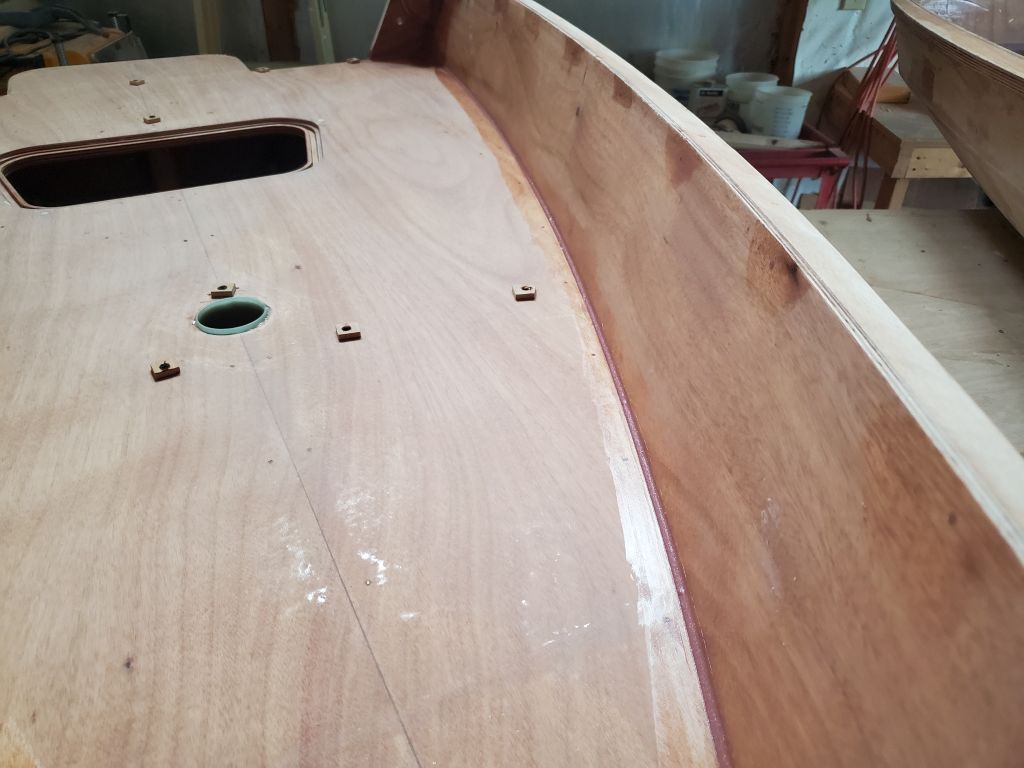
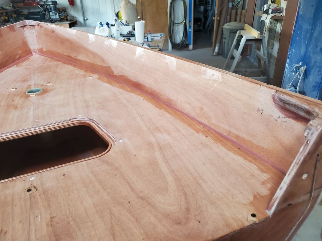
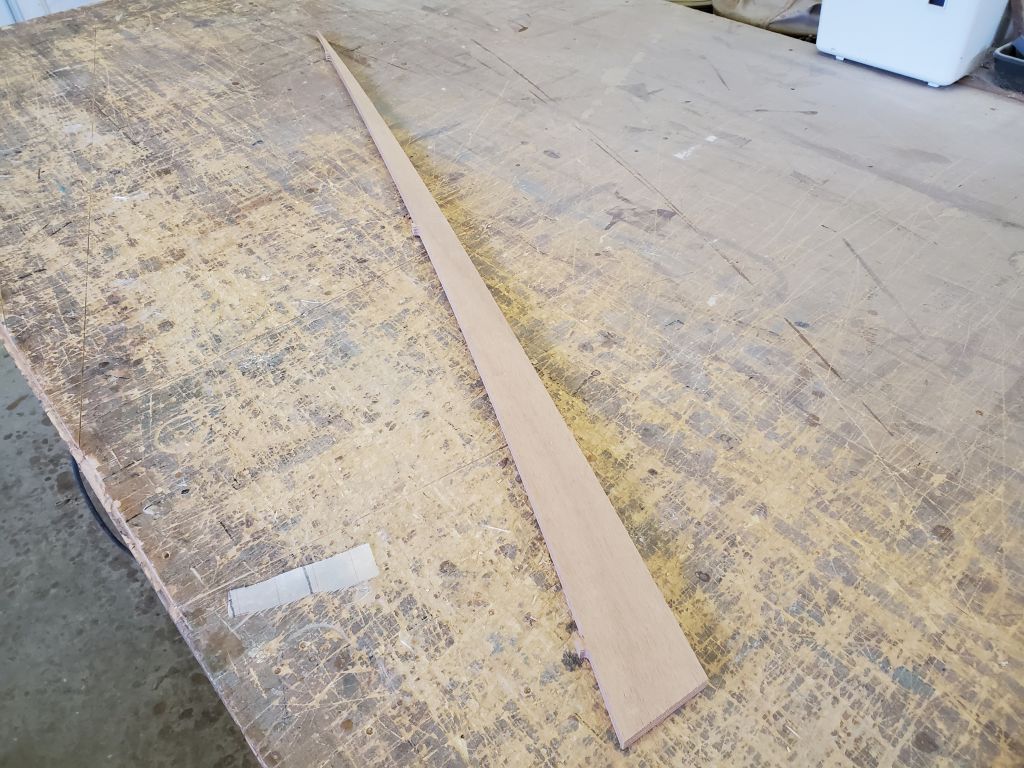
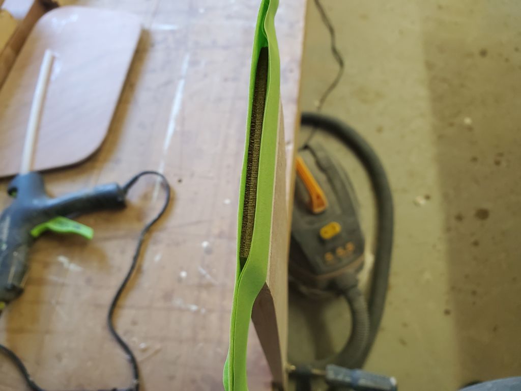
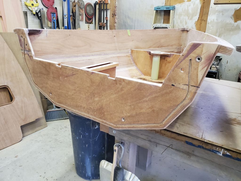
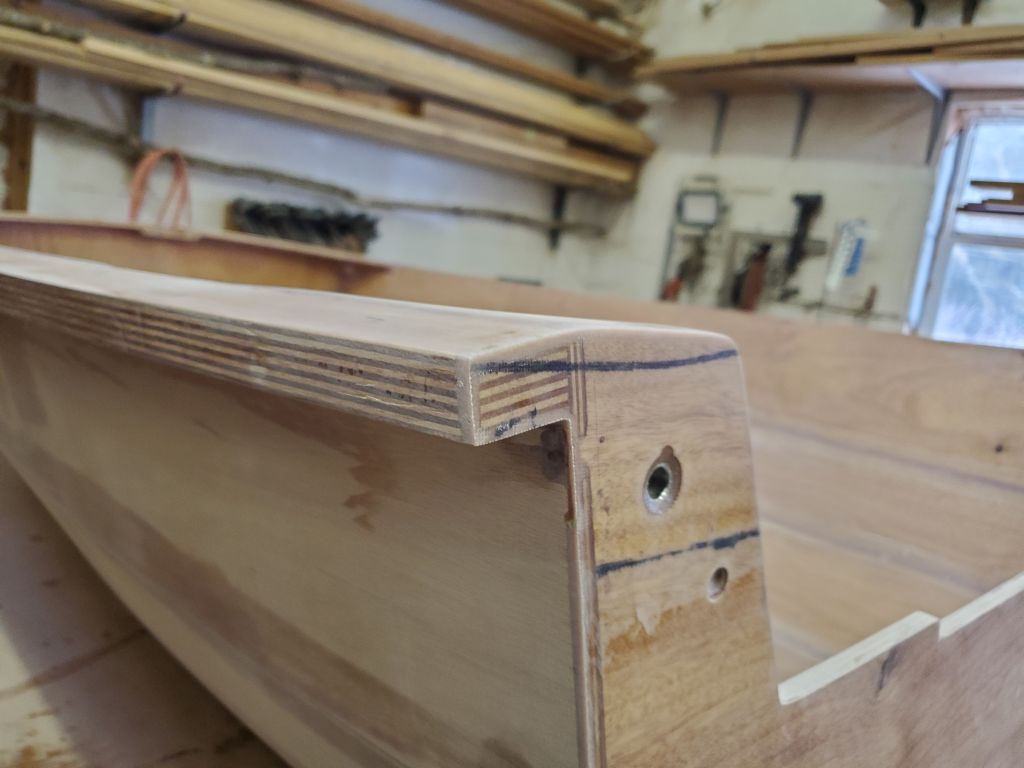
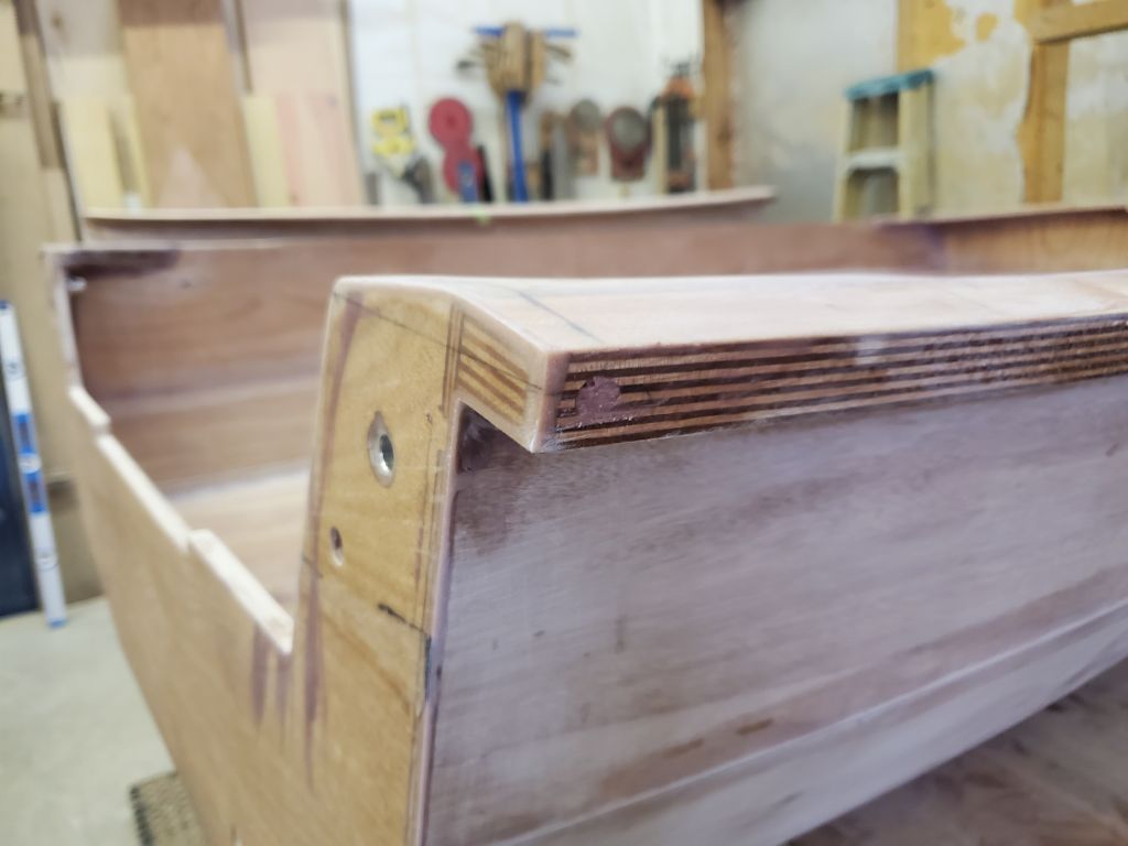
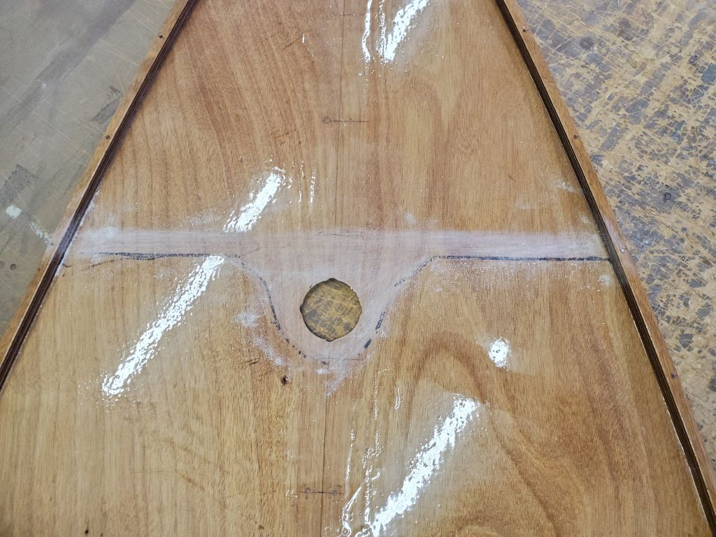
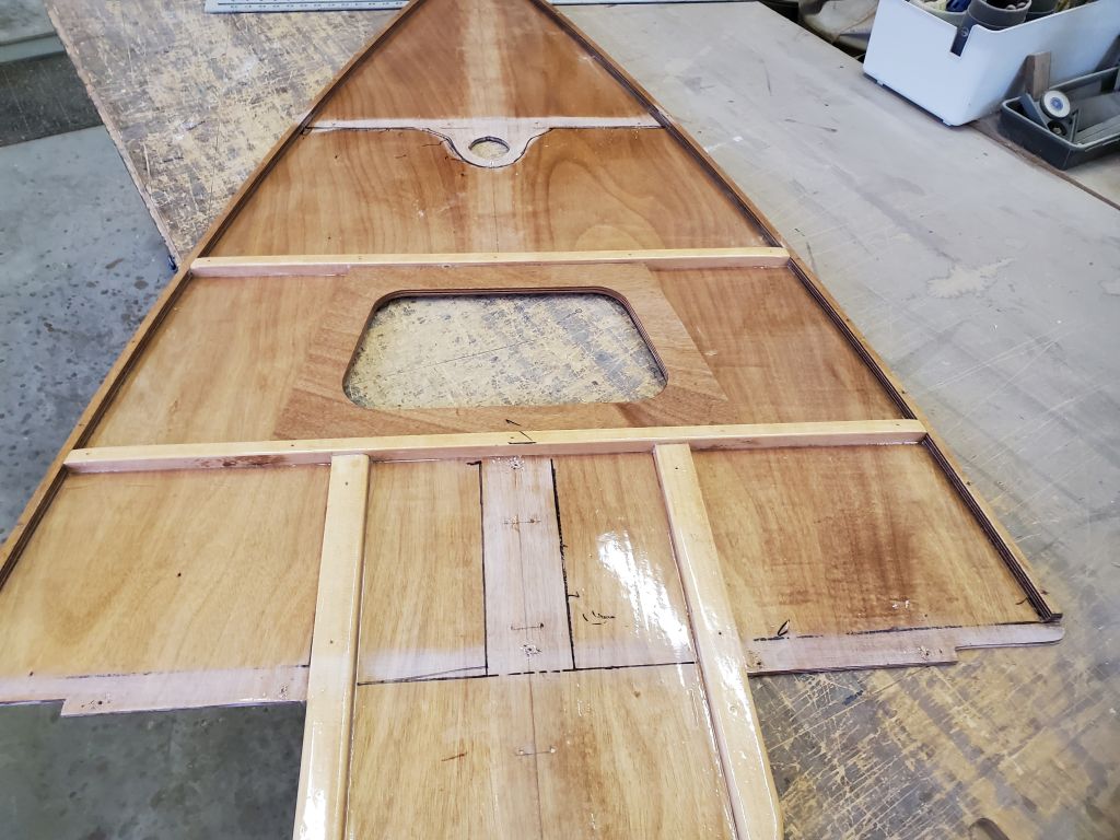
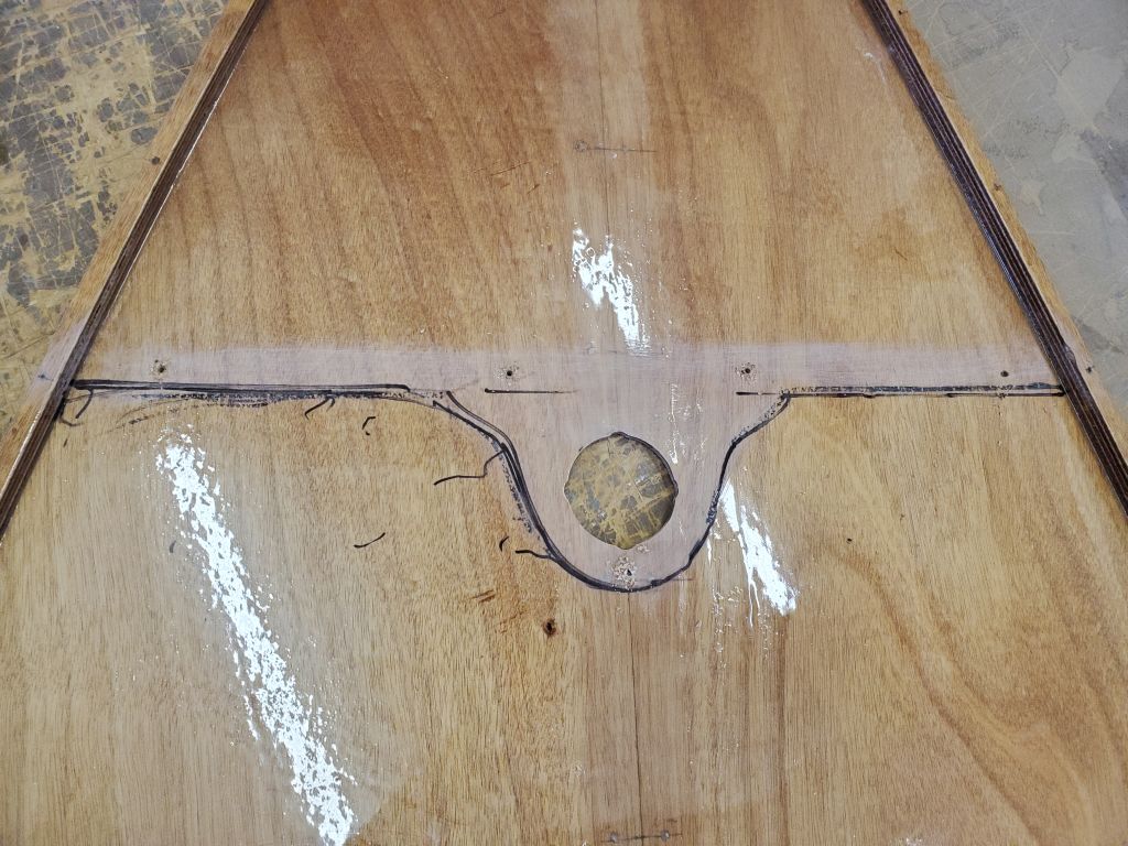
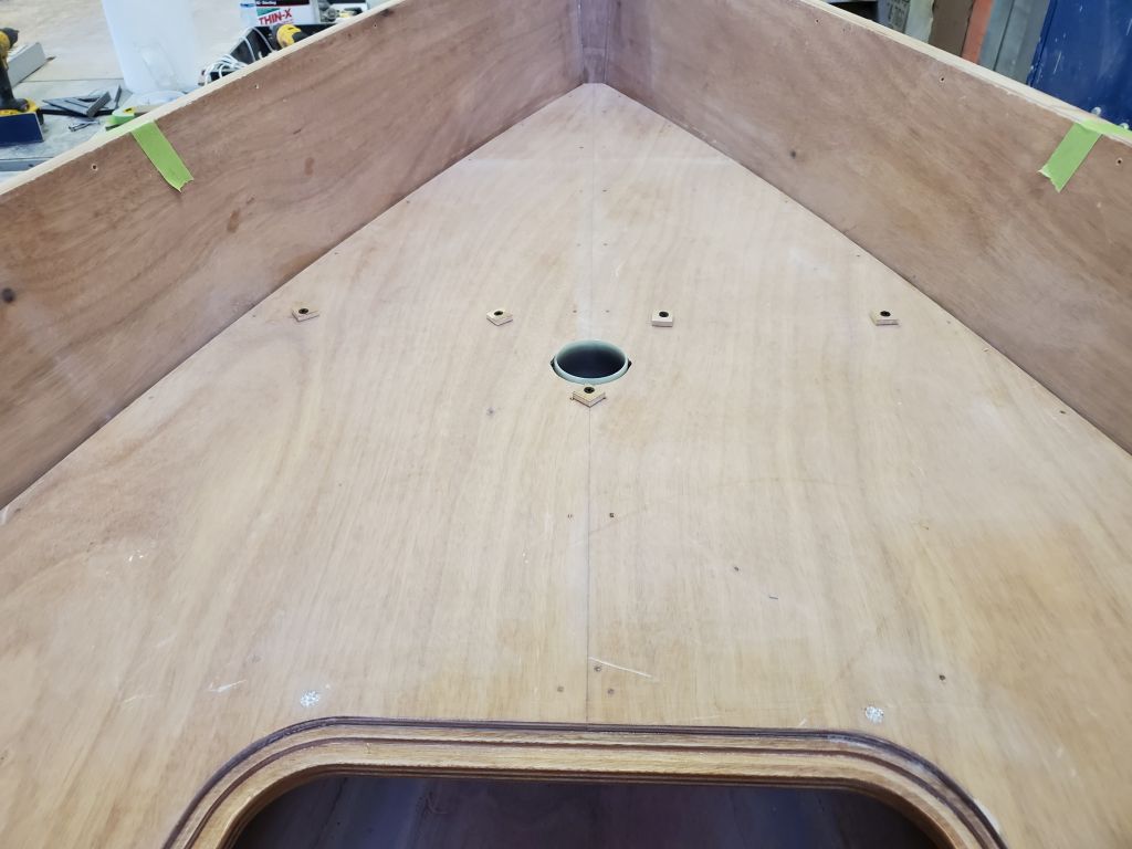
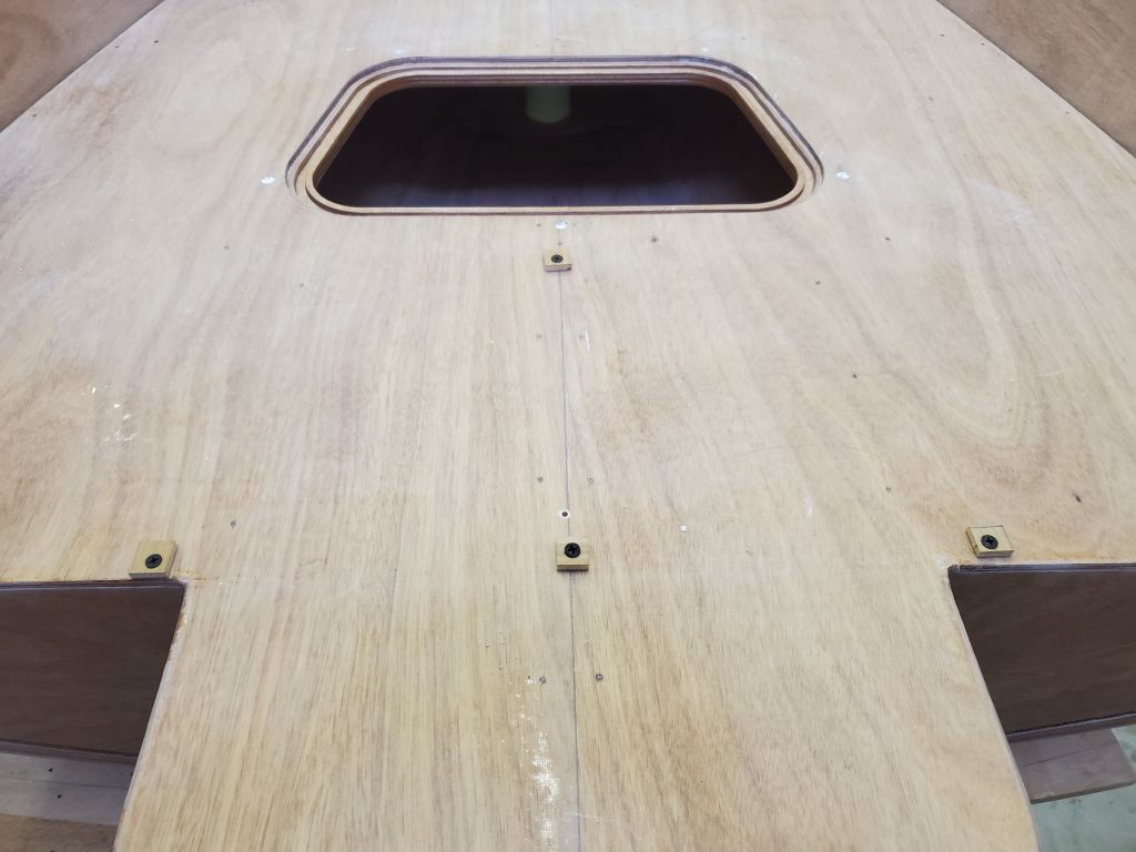
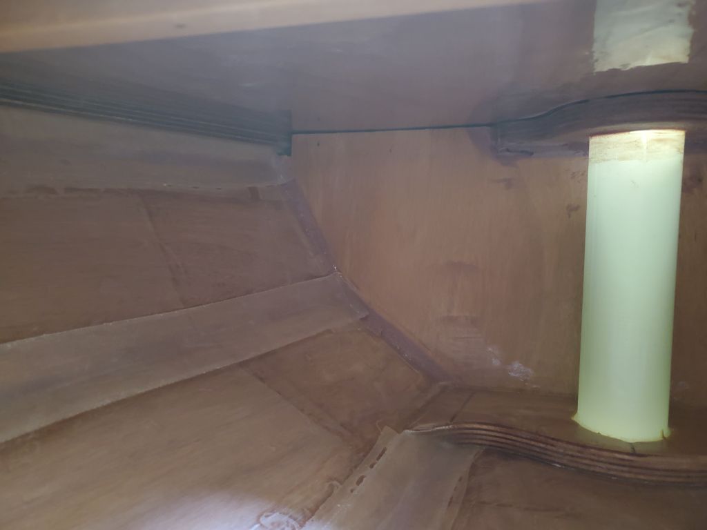
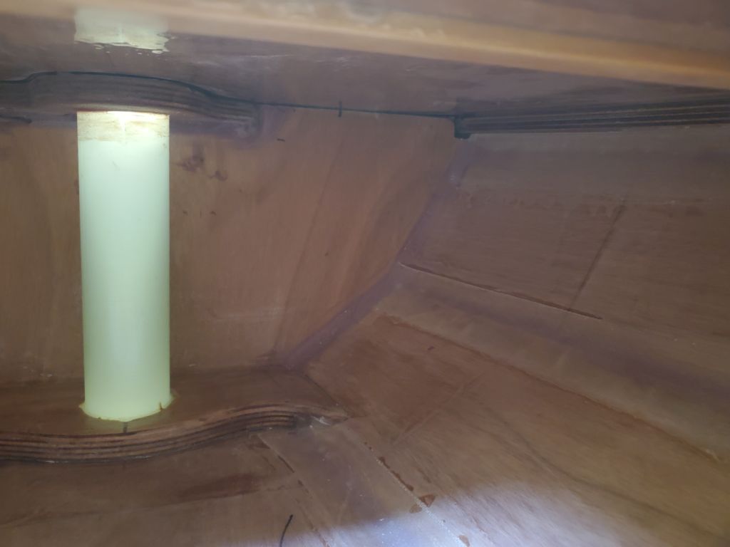
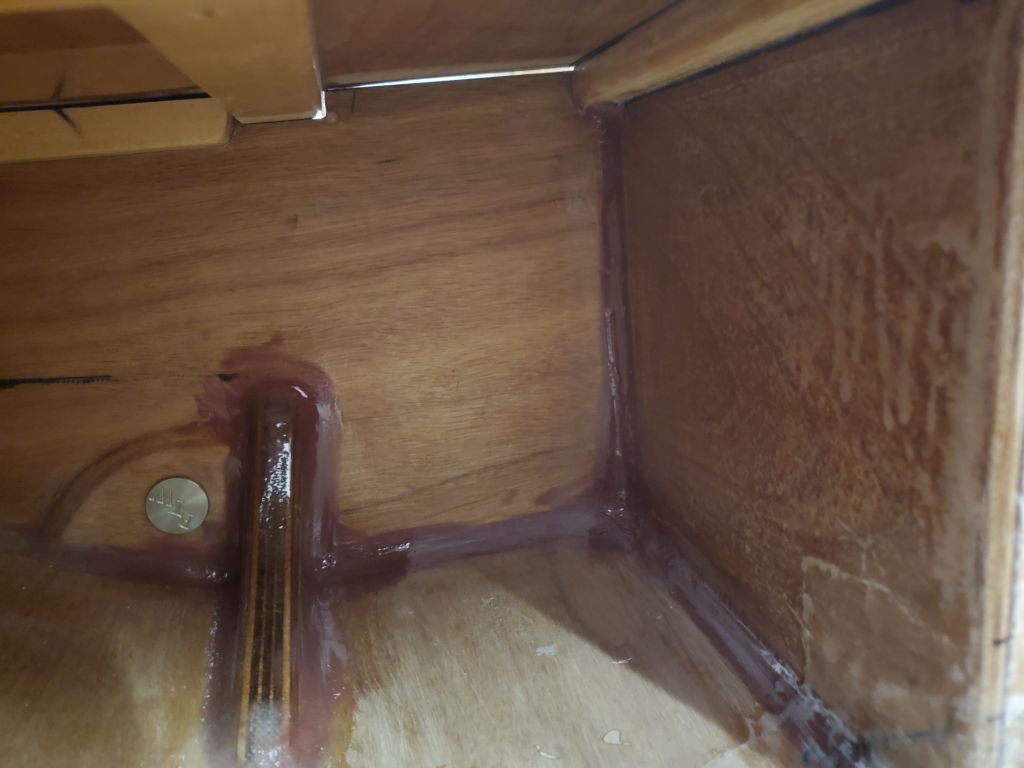
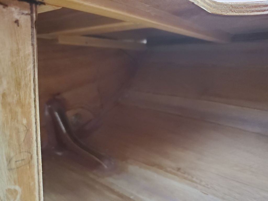
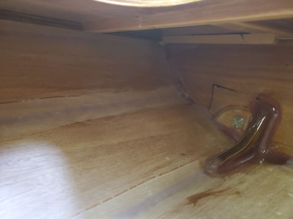
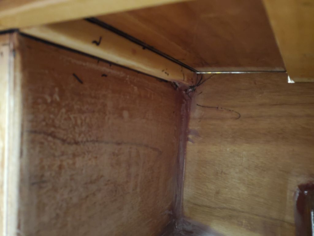
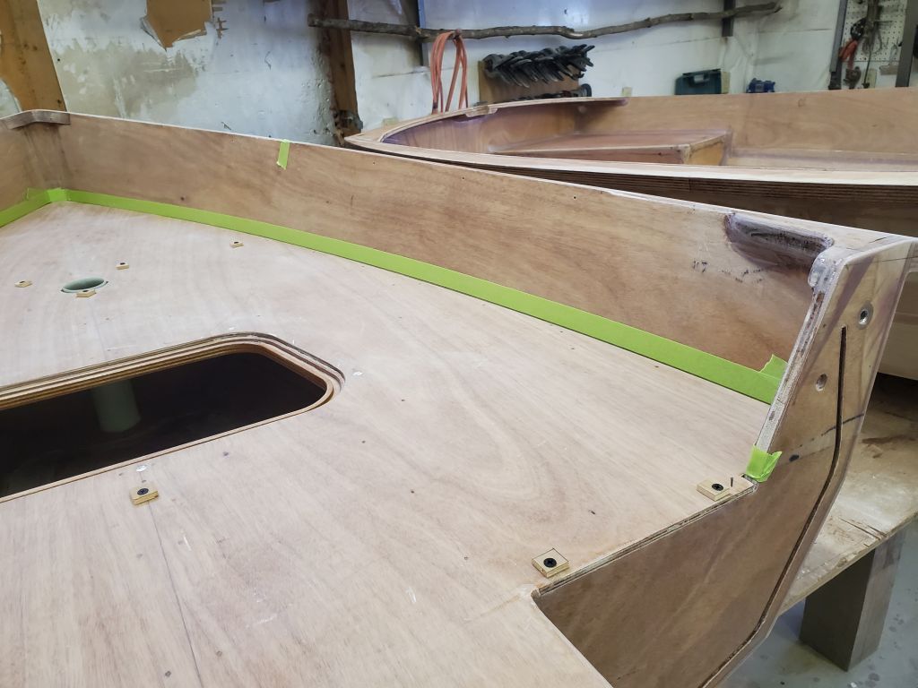
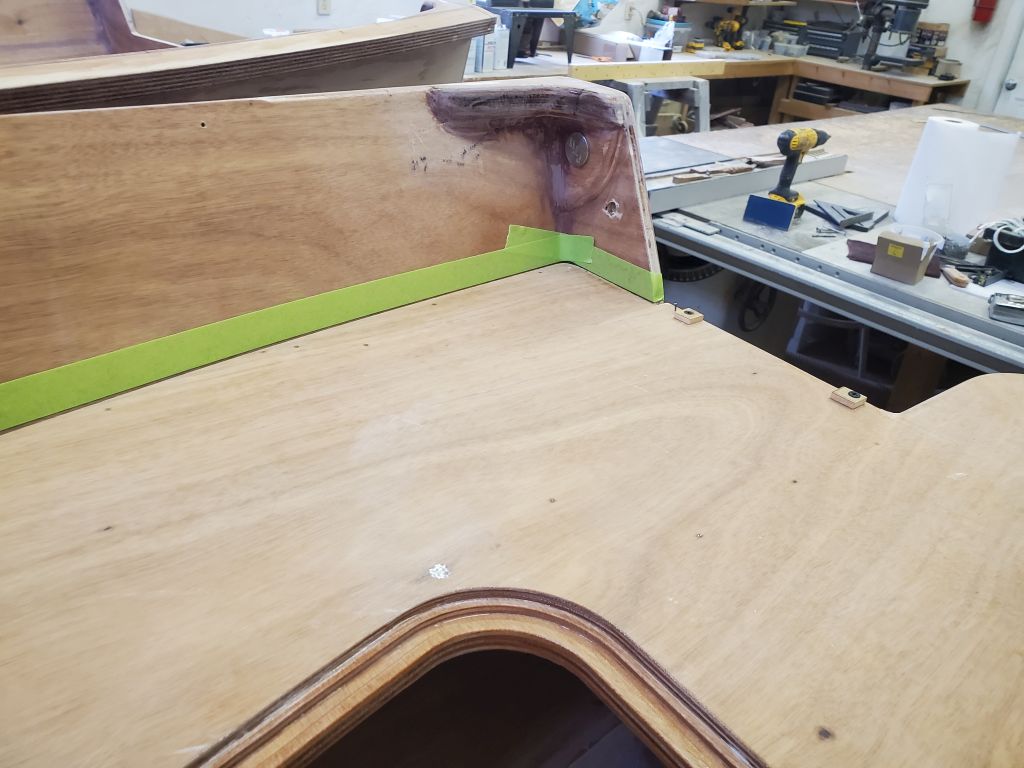
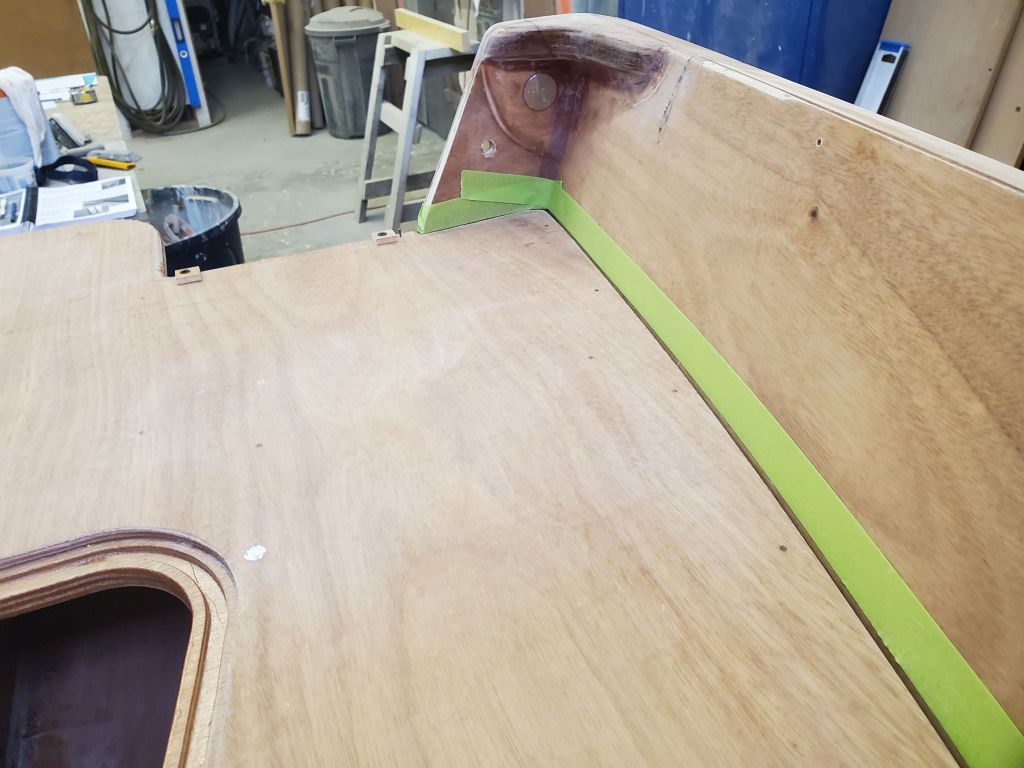
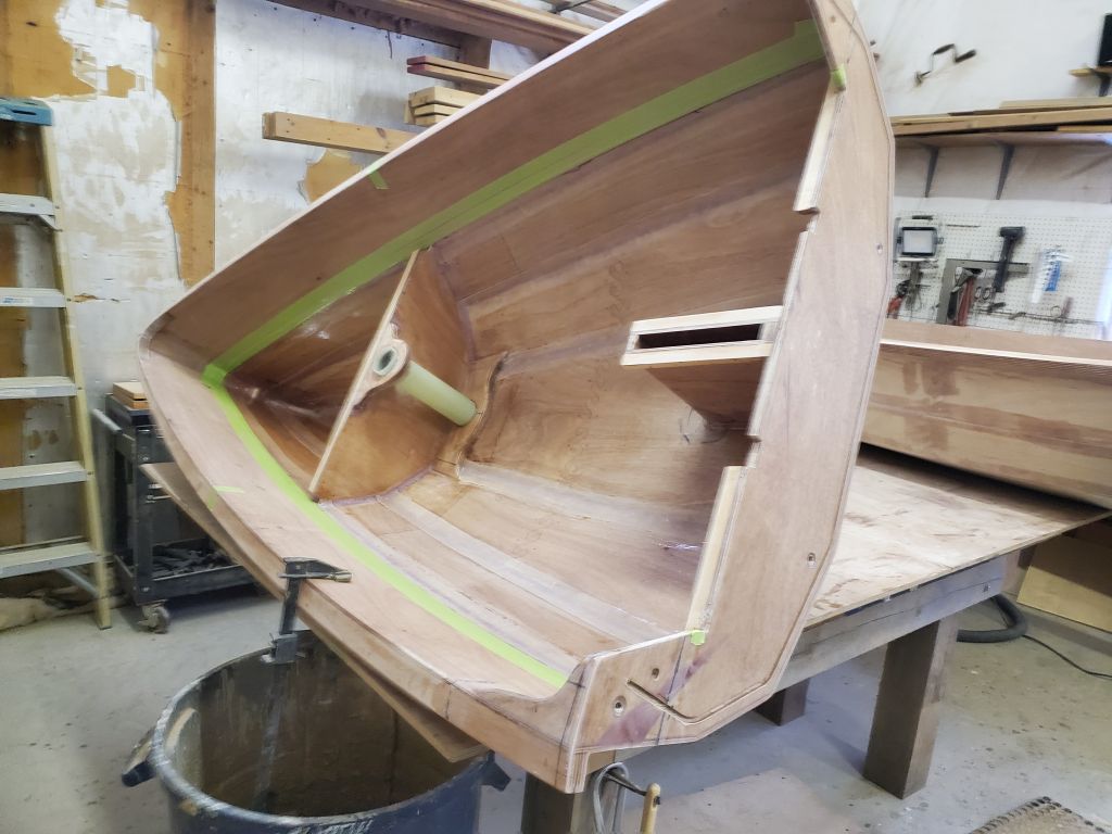
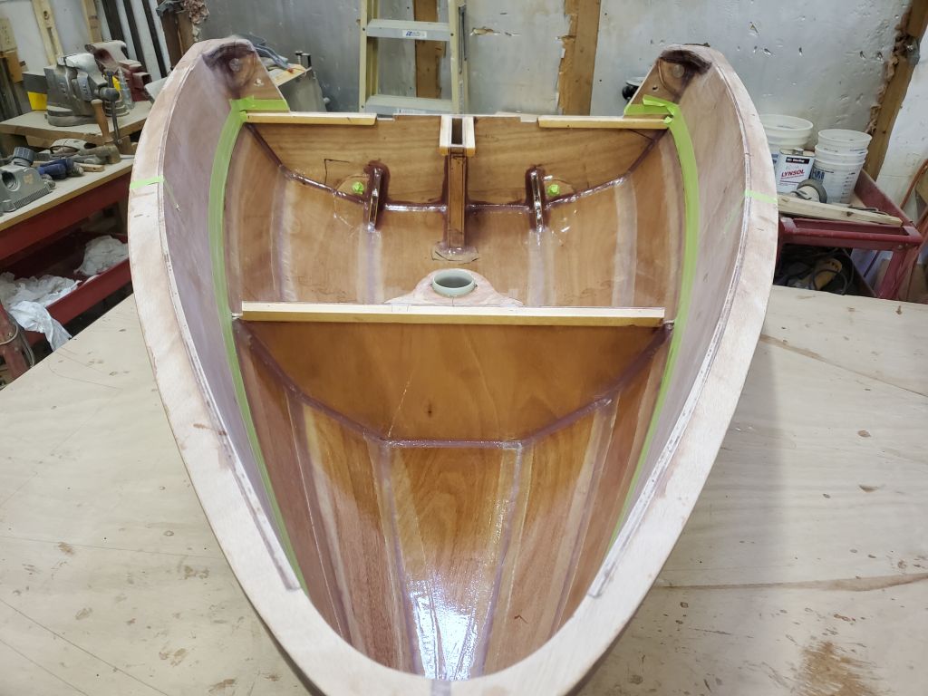
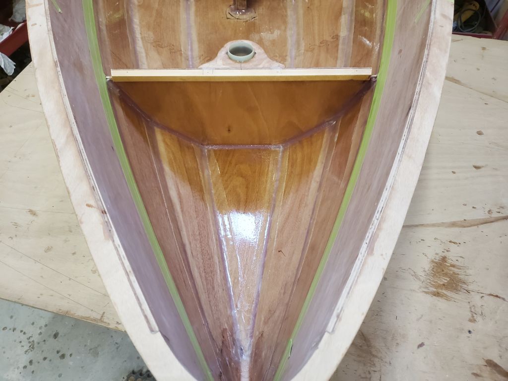
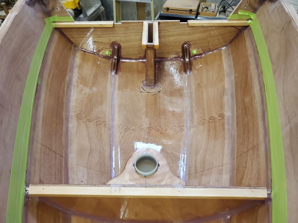
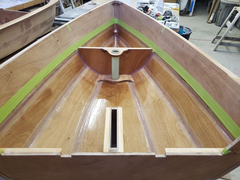
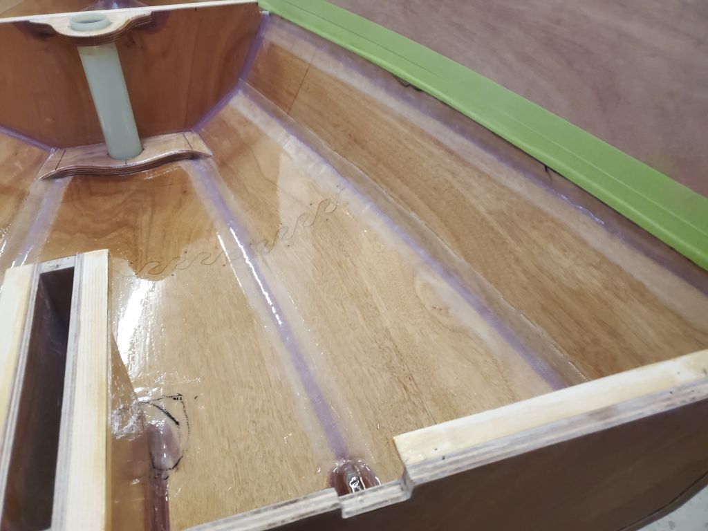
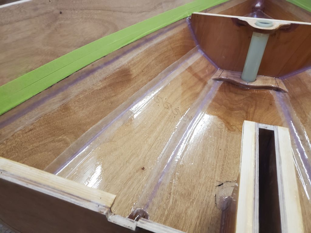
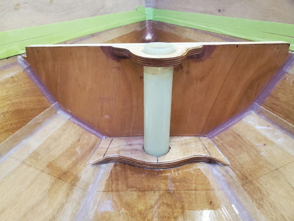
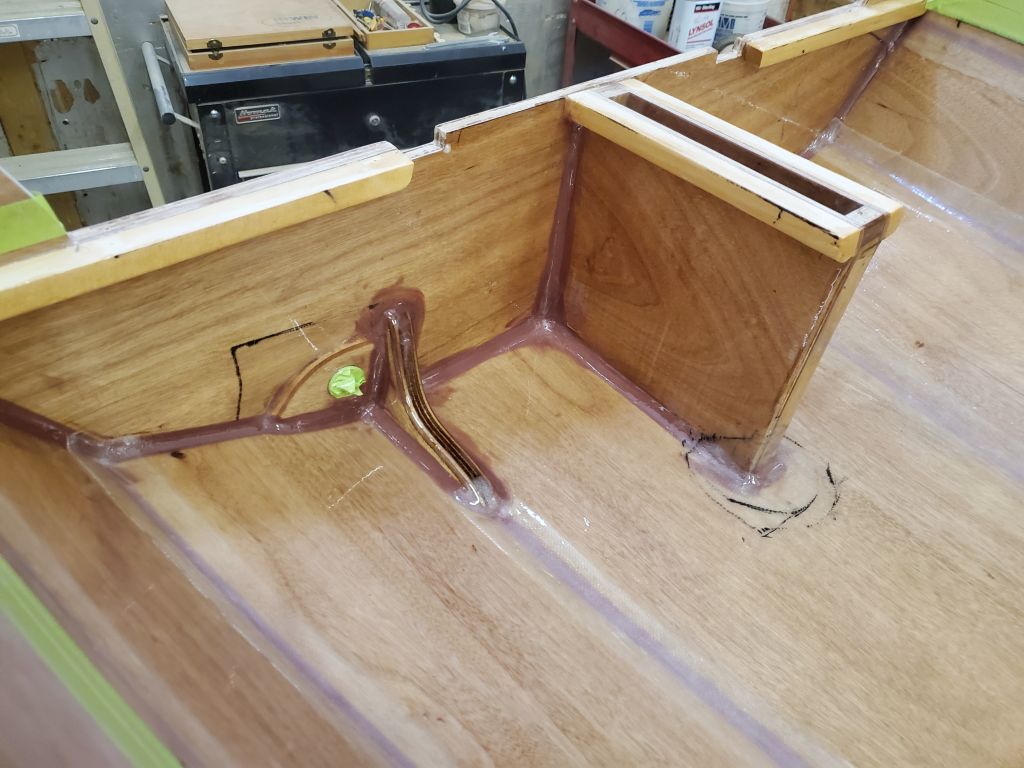
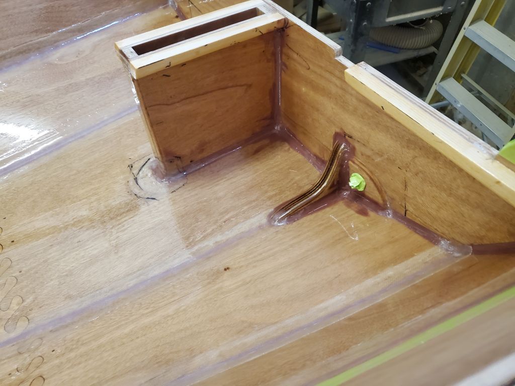
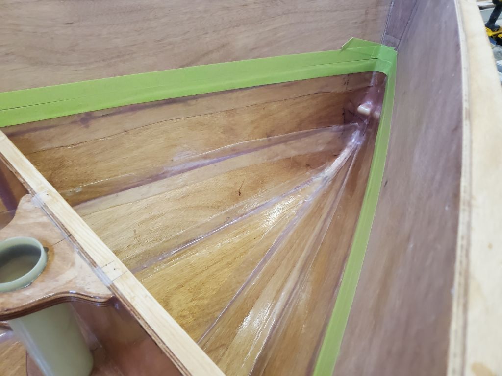
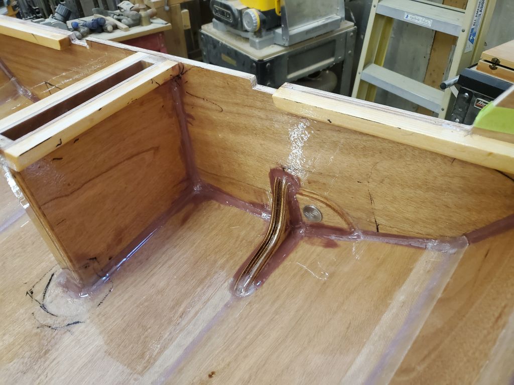
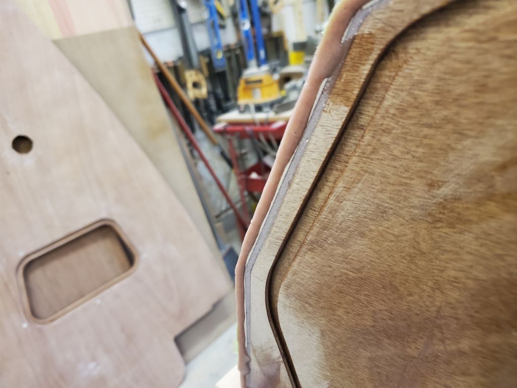
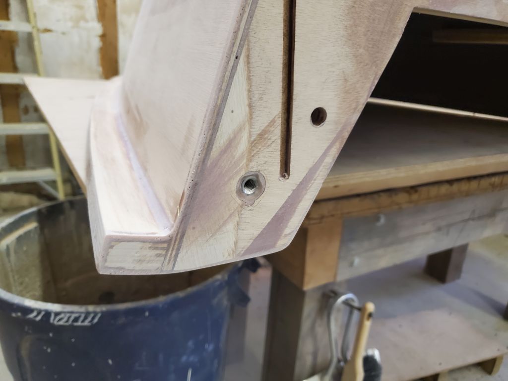
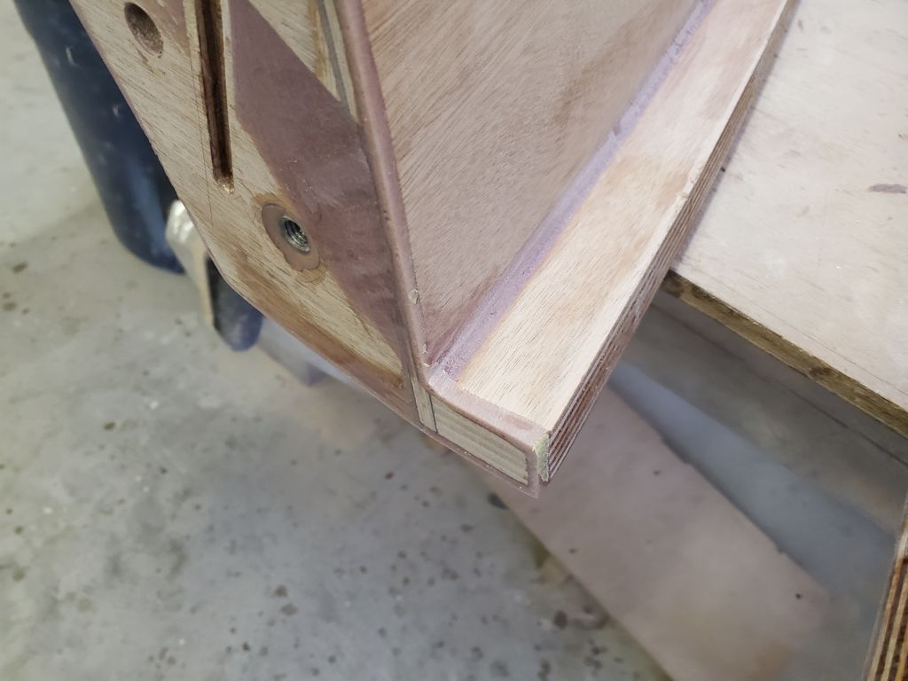
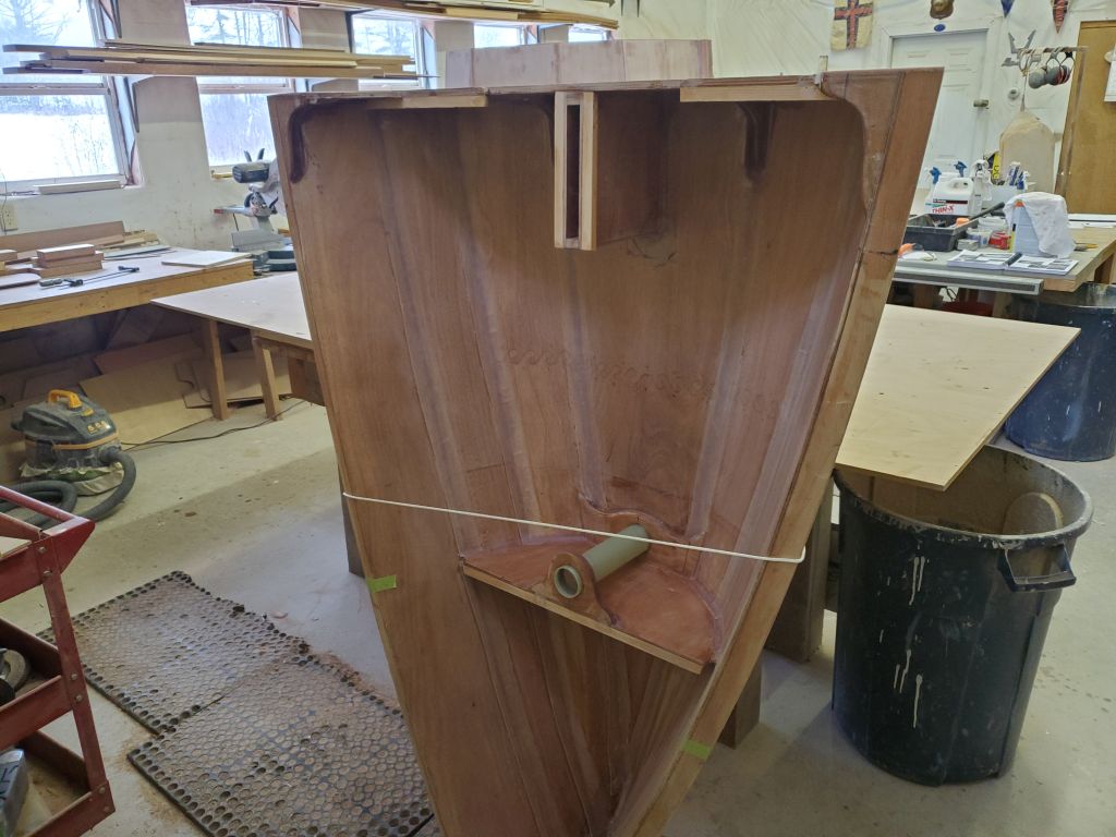
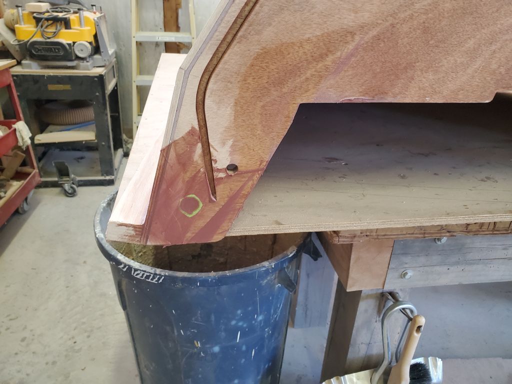
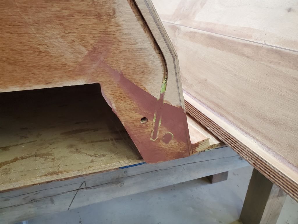
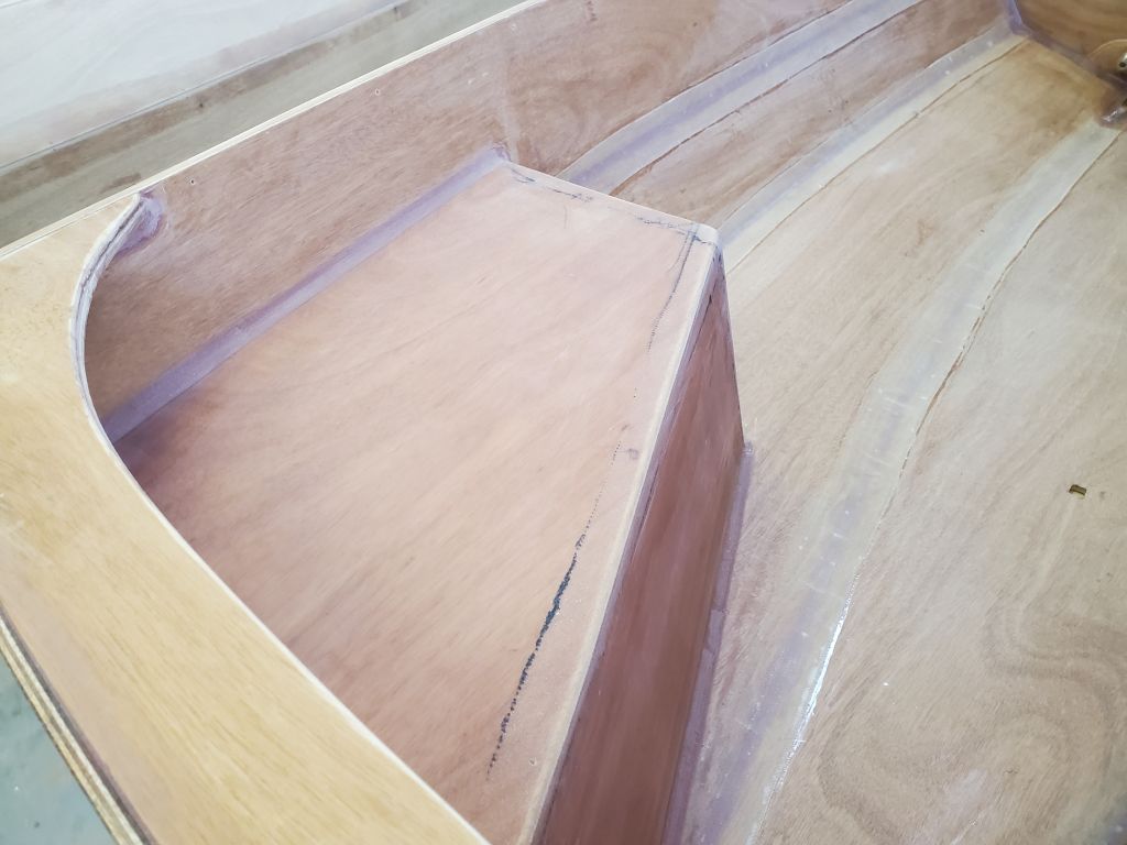
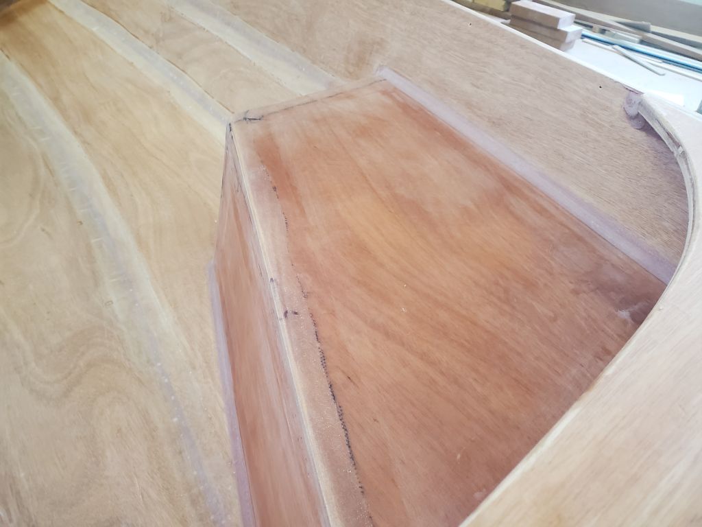
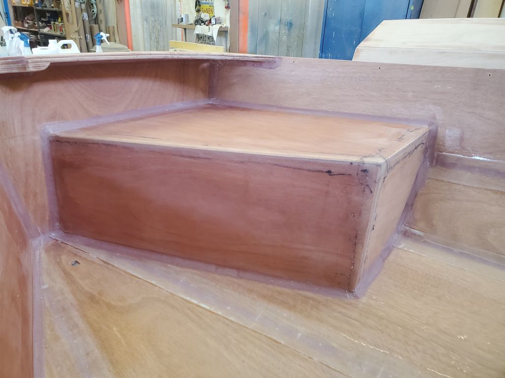
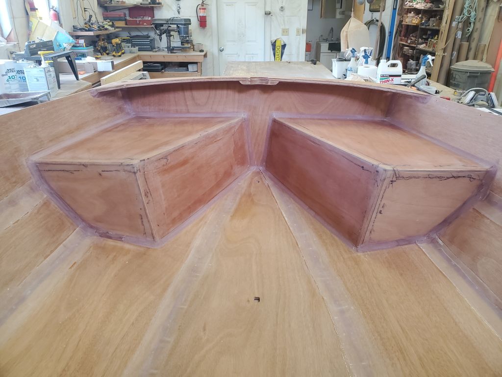
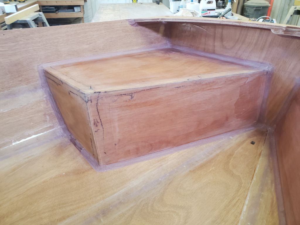
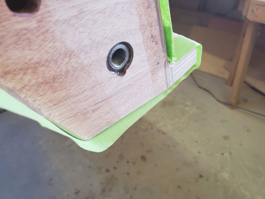
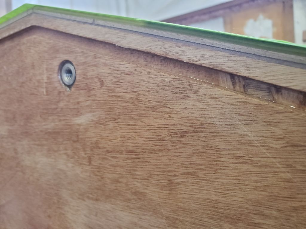
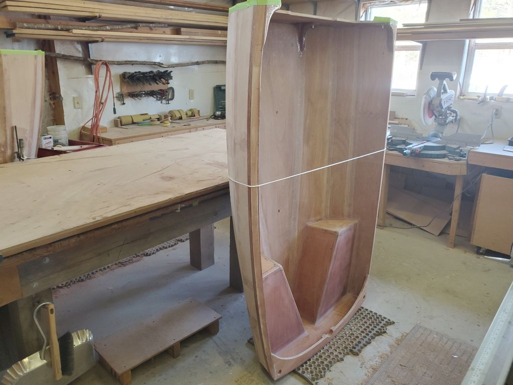
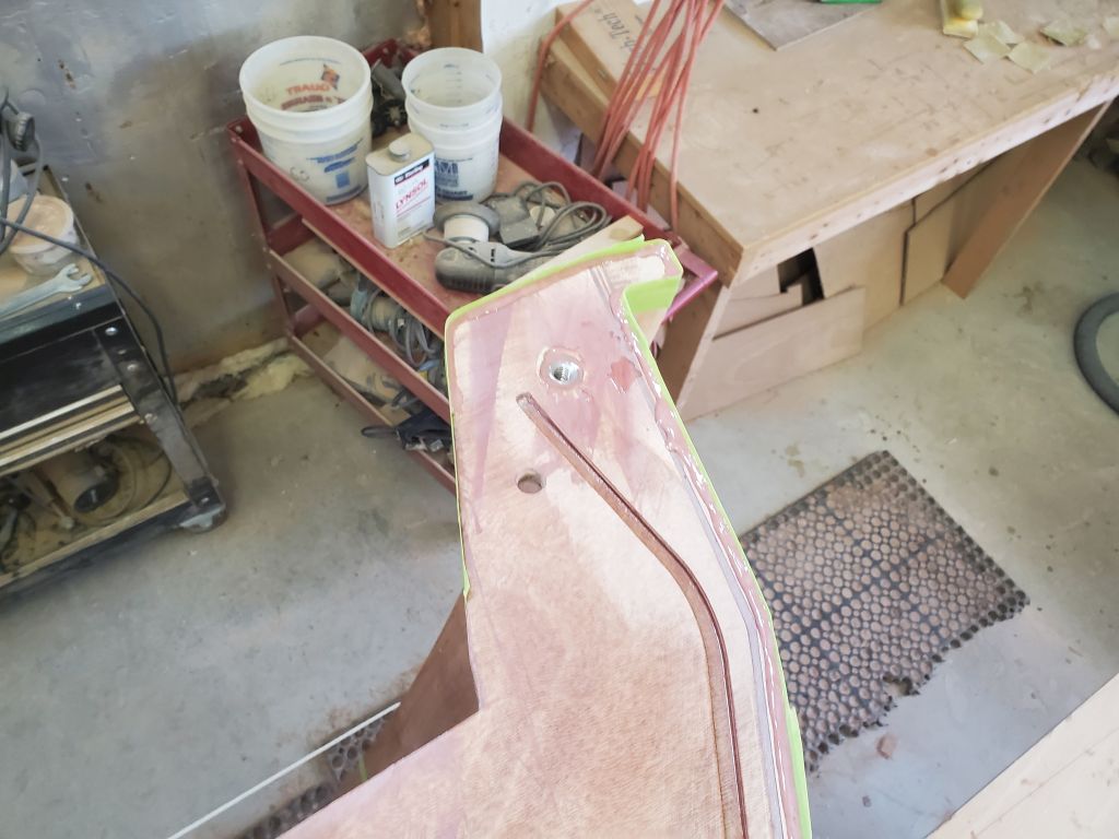
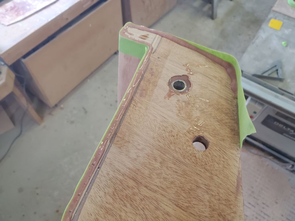
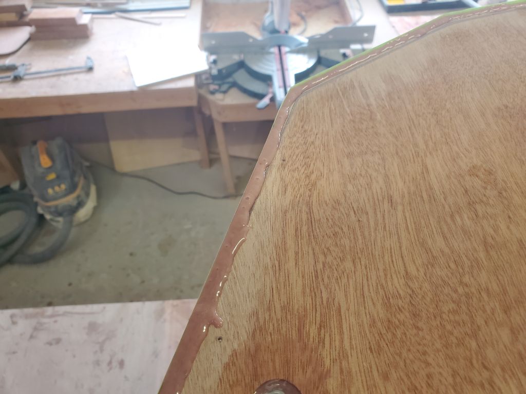
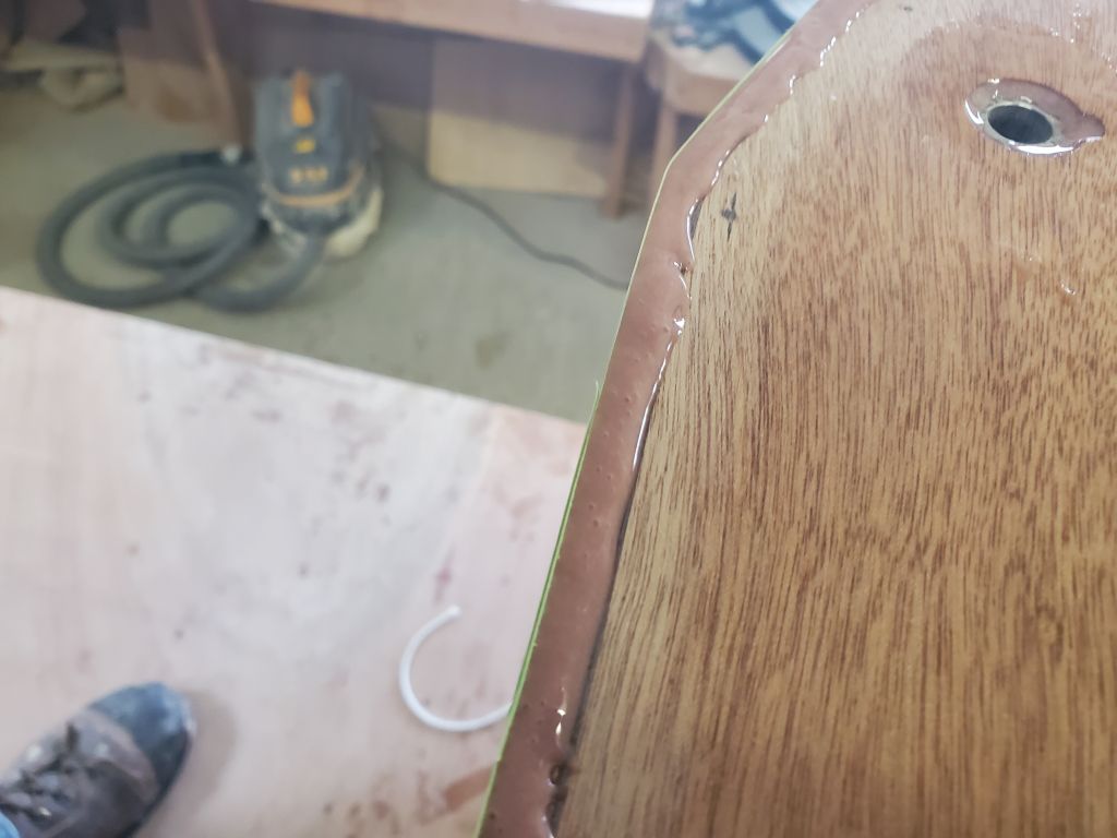
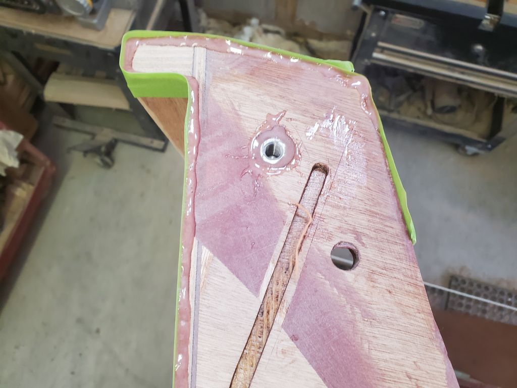
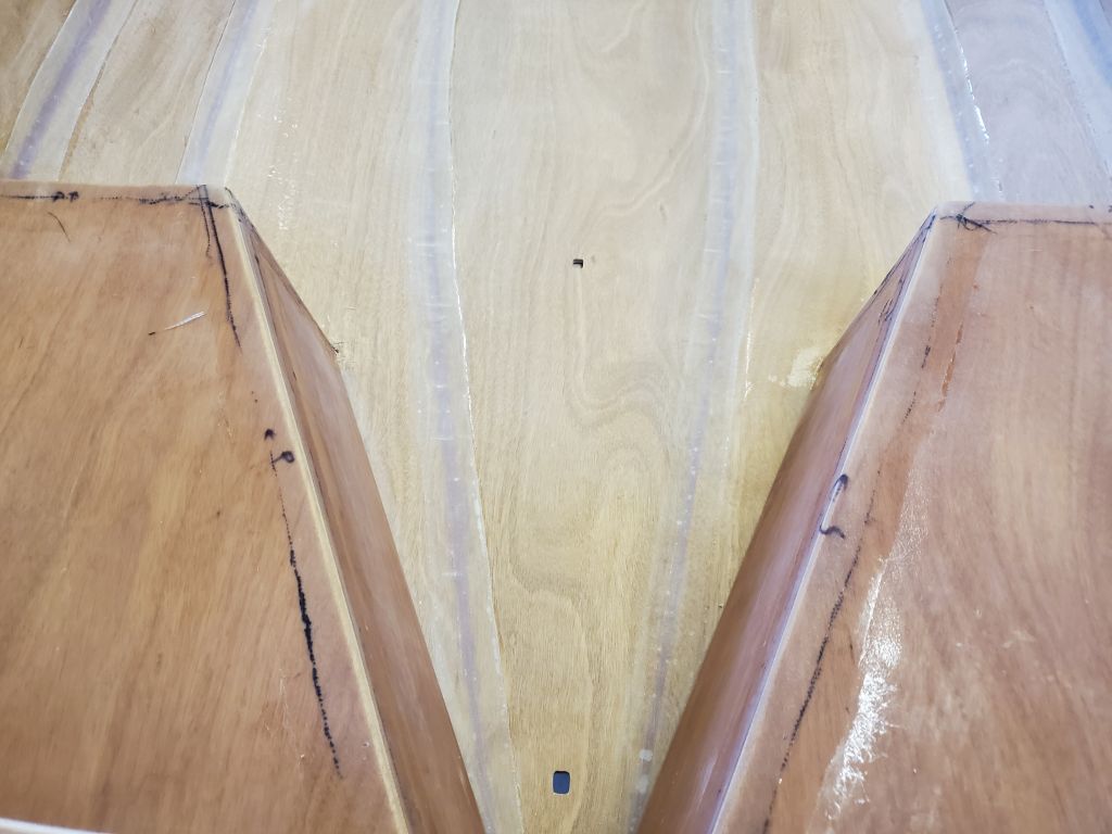
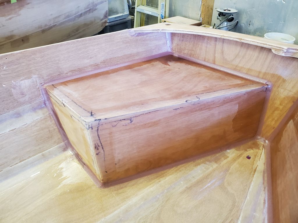
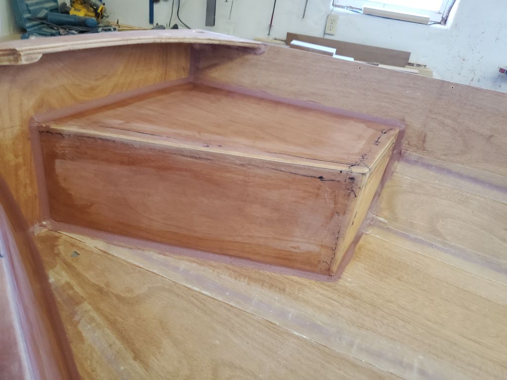
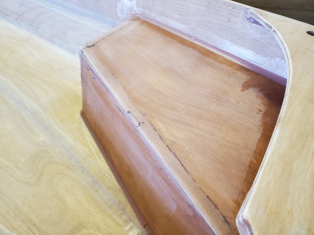
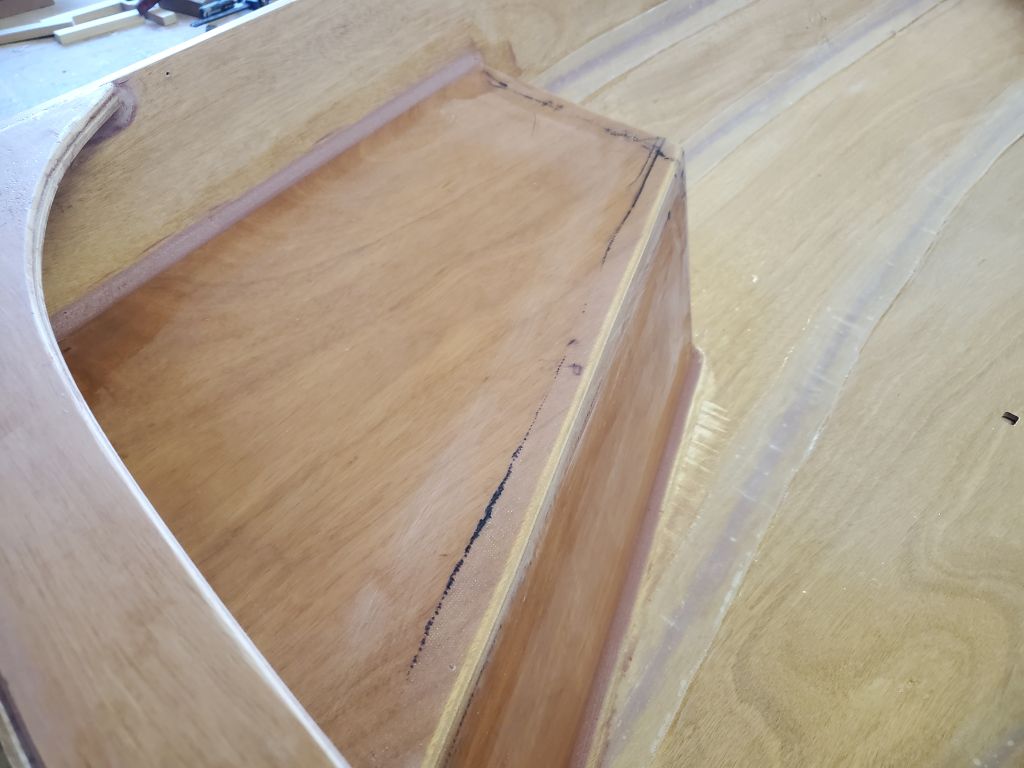
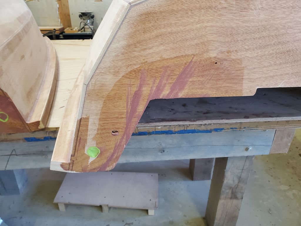
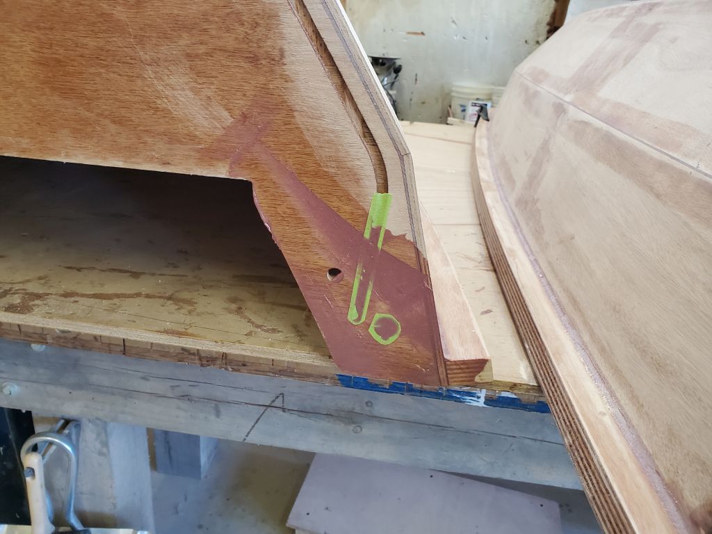
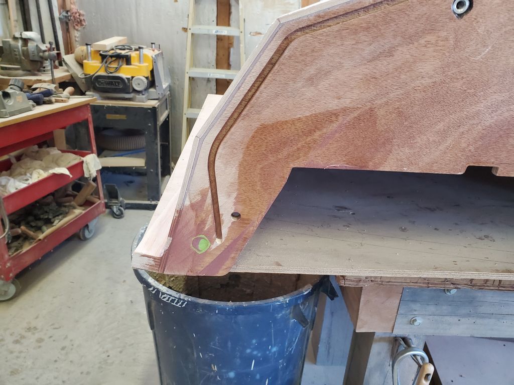
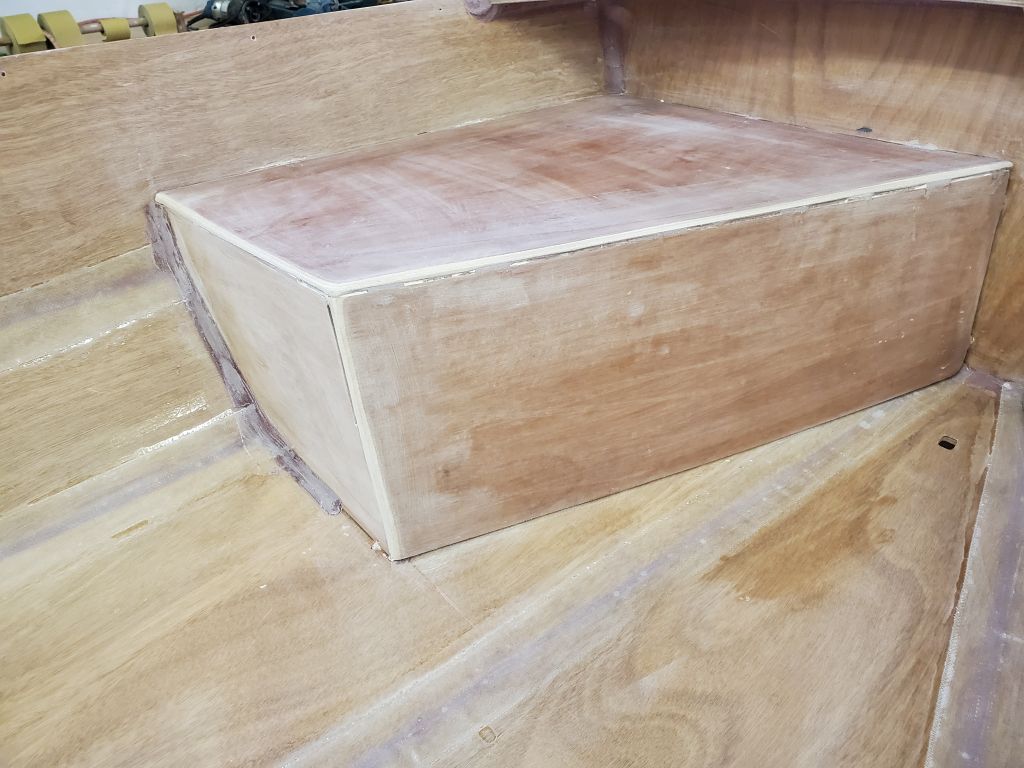
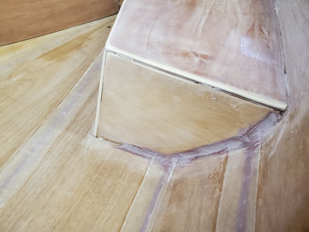
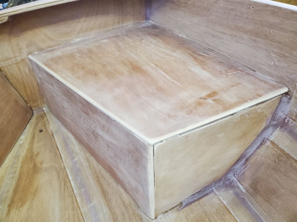
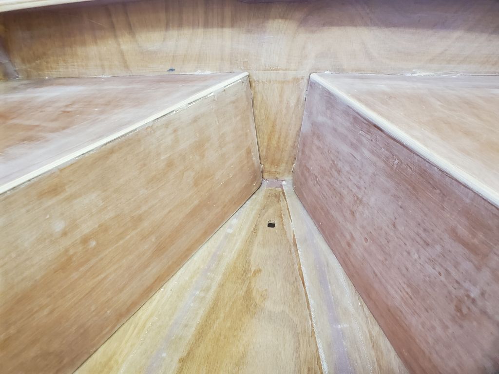
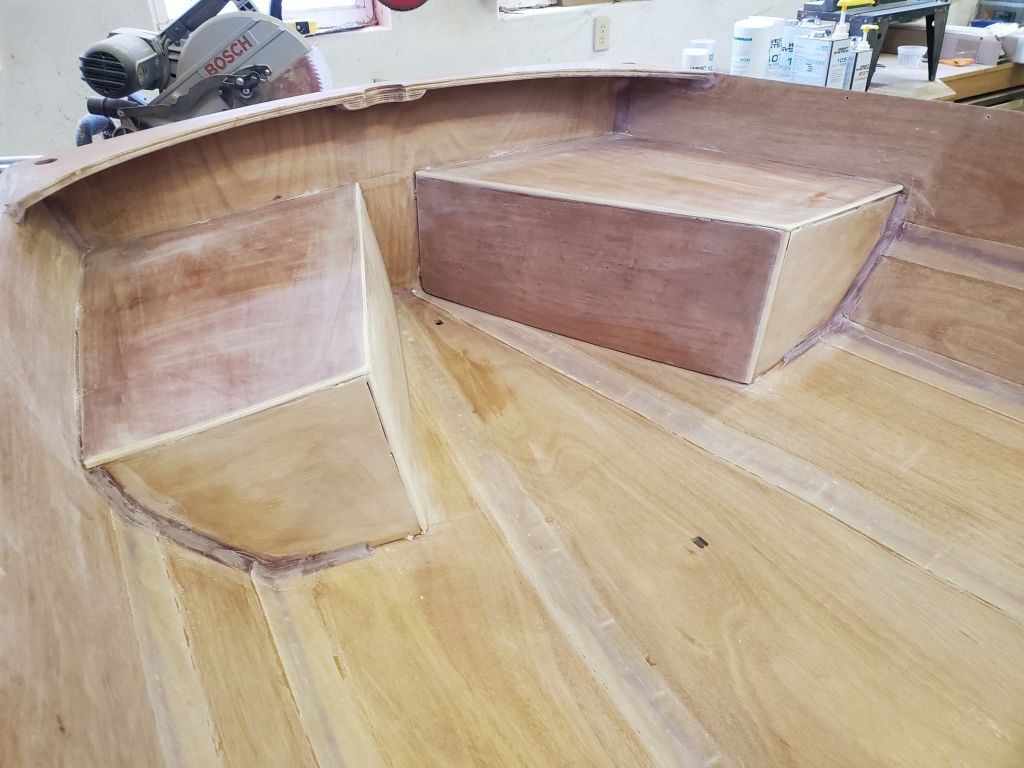
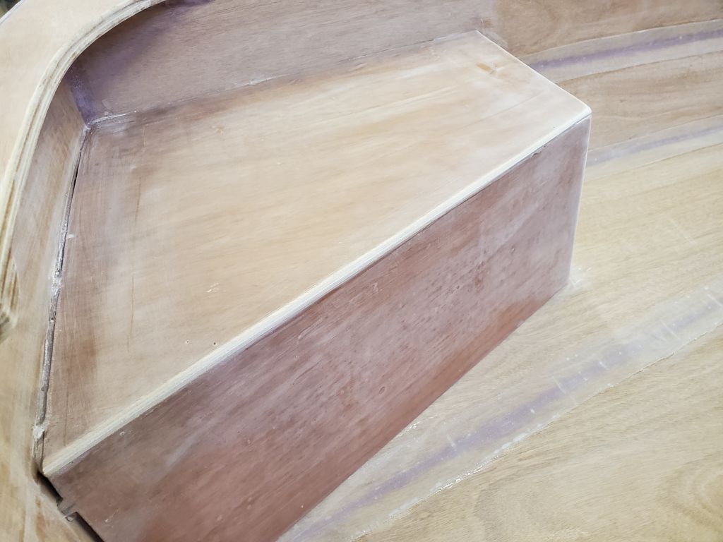
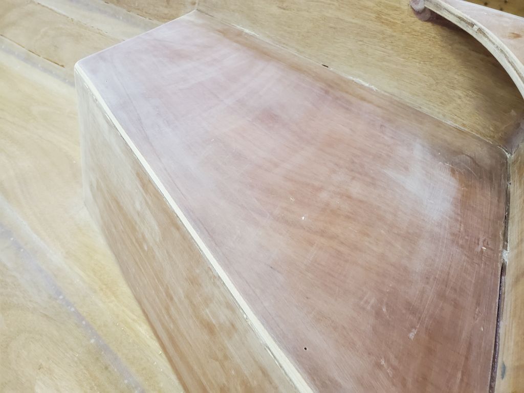
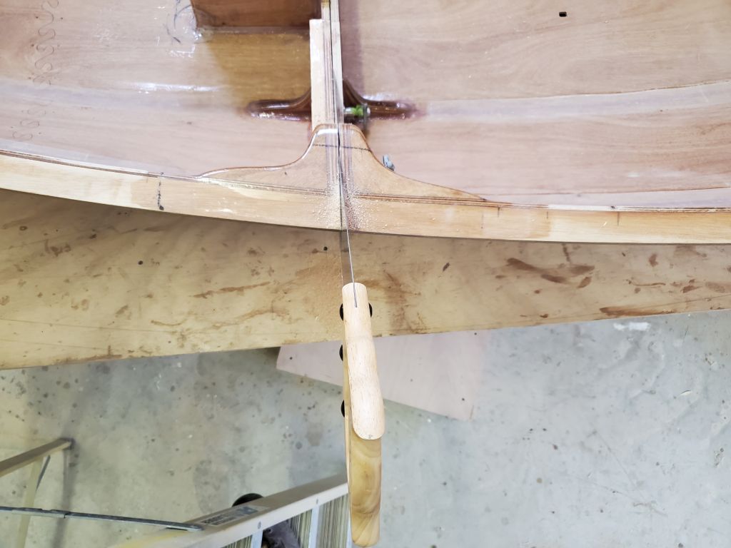
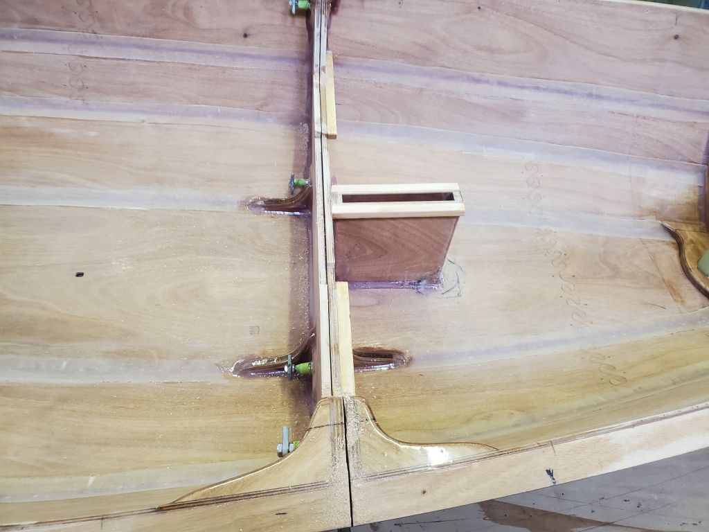
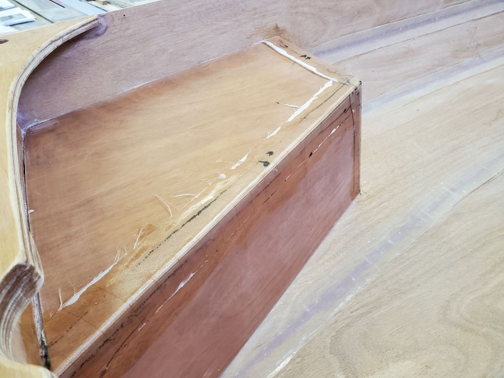
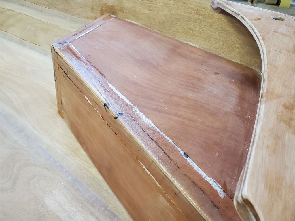
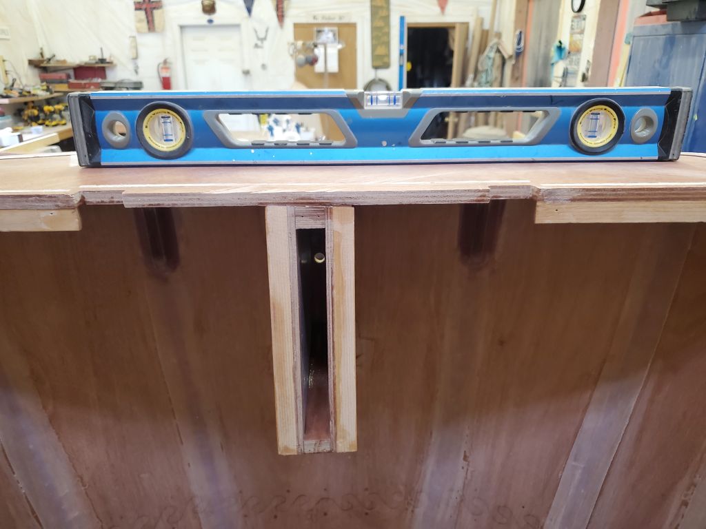
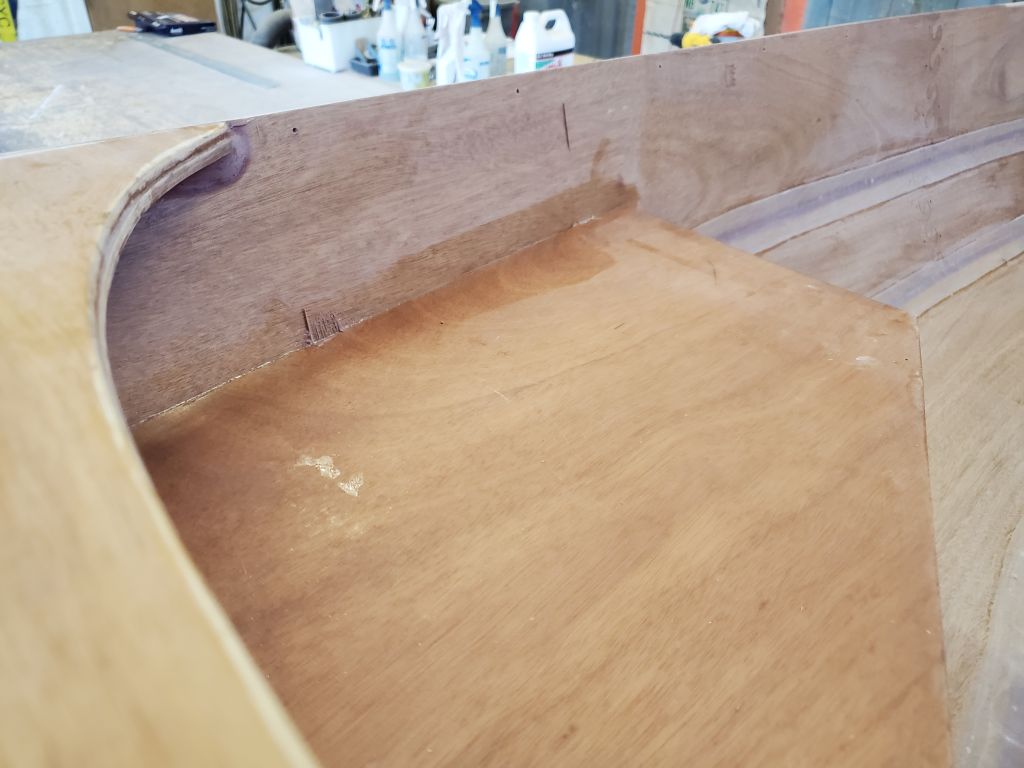
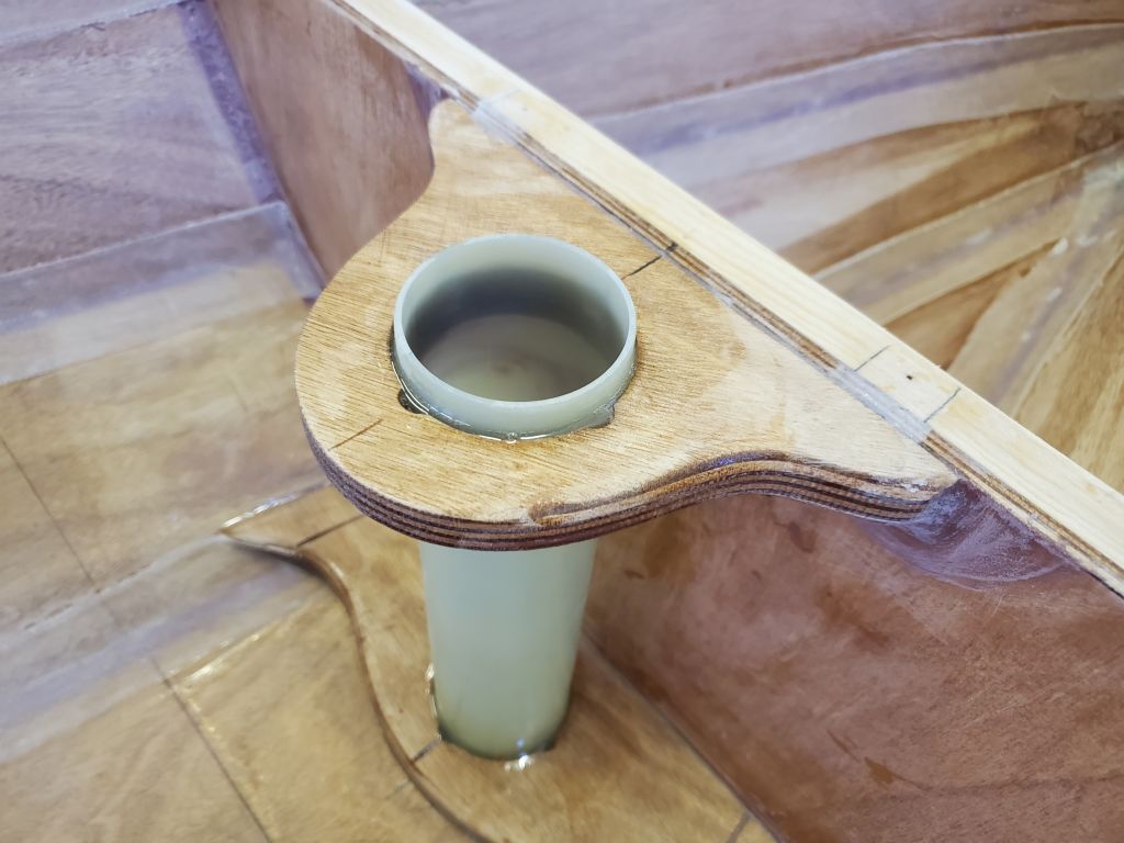
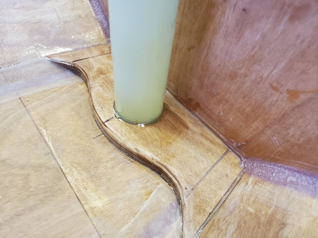
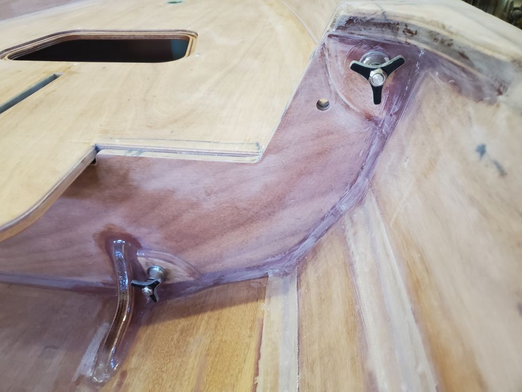
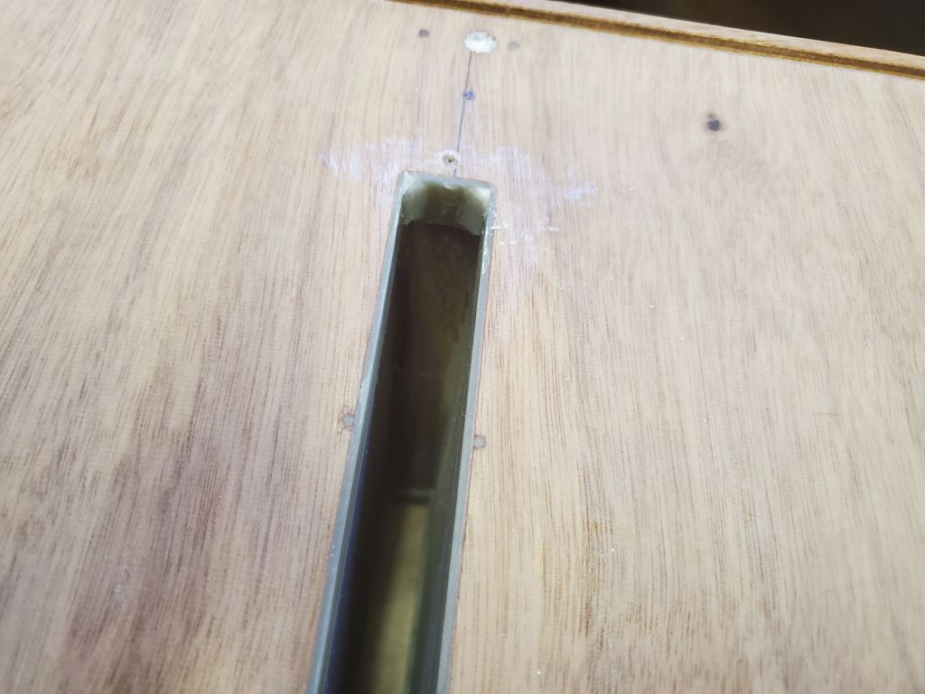
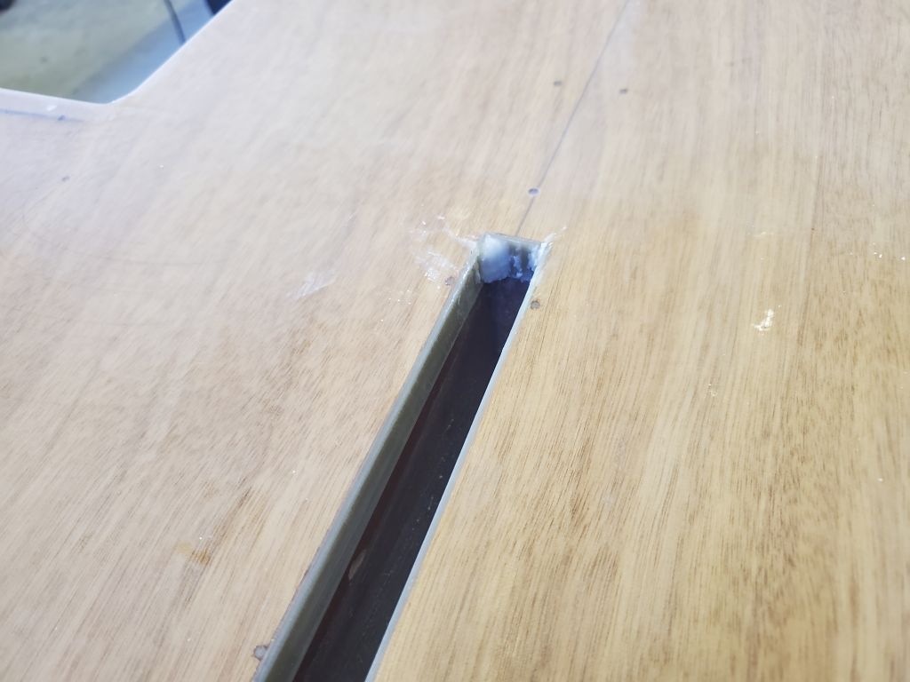
I did a little more work on the daggerboard trunk next. With the fiberglass strips now cured, I added some small epoxy fillets in the four corners on each side of the boat (foredeck and bottom). Those fillets could cure and be ready when I was ready to sand these slots flush with the foredeck and hull in another day or so. For now, this wouldn’t affect what I wanted to do next.
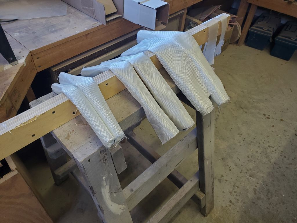
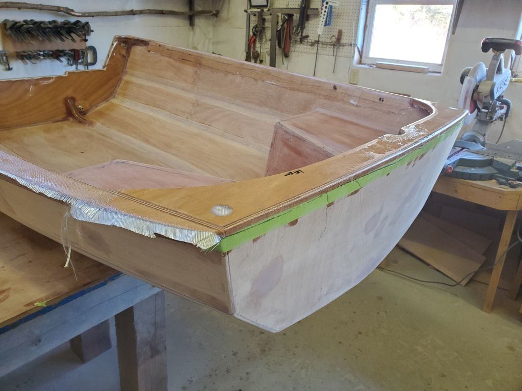
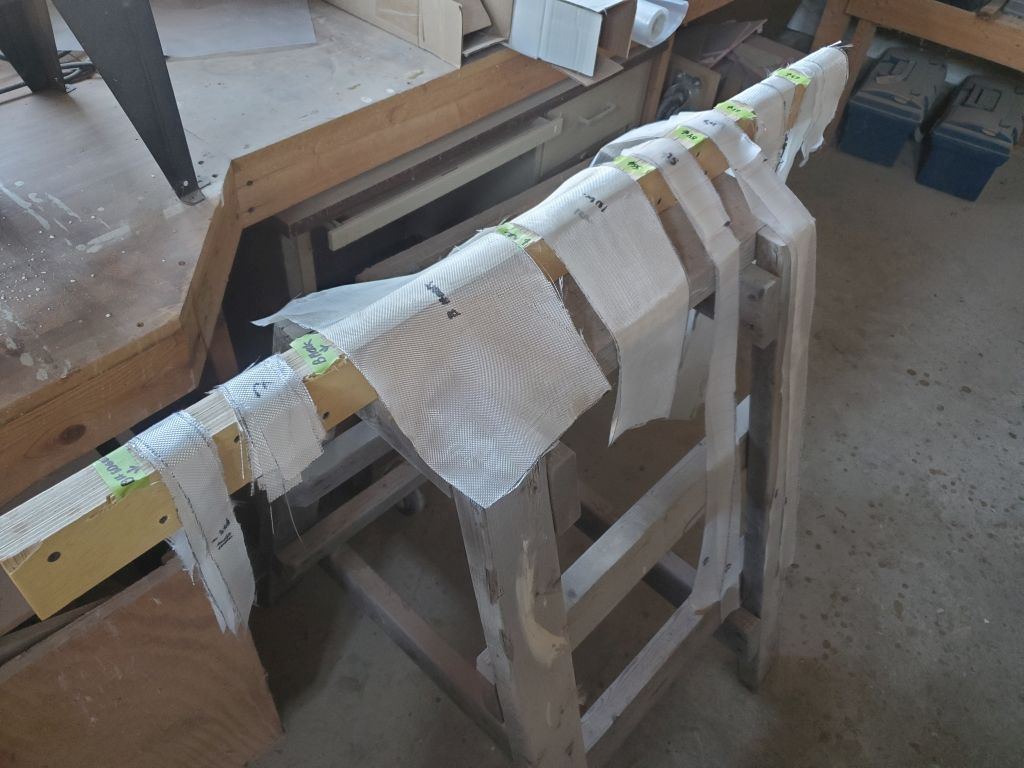
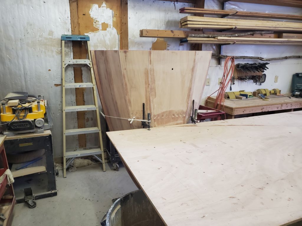
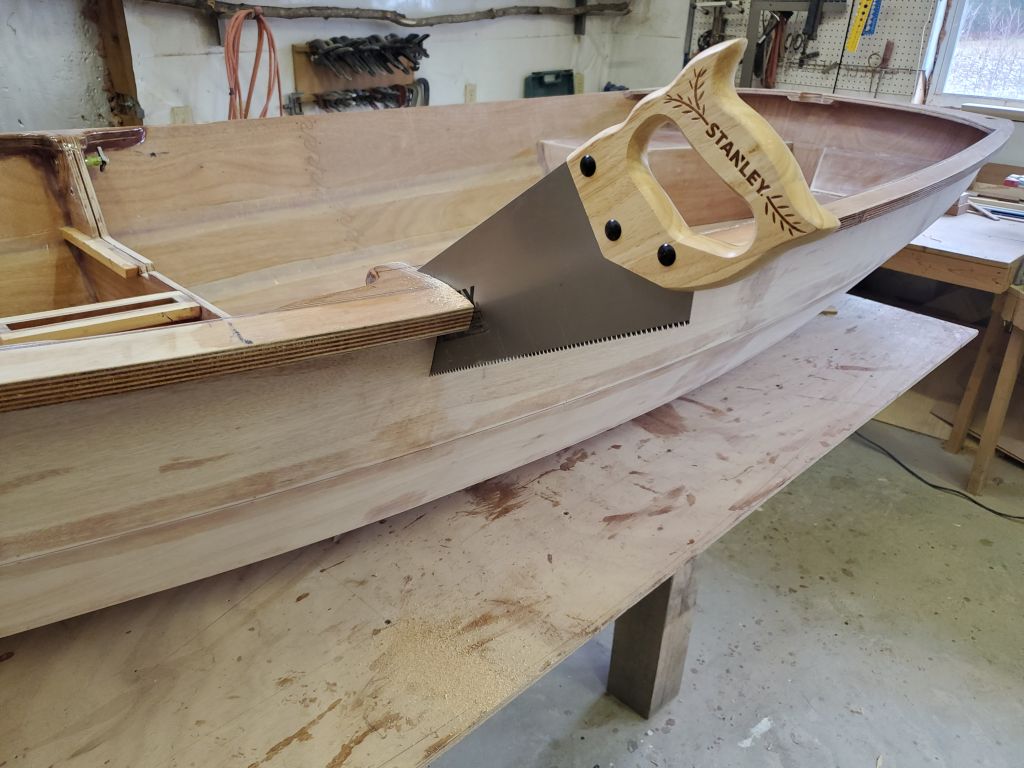
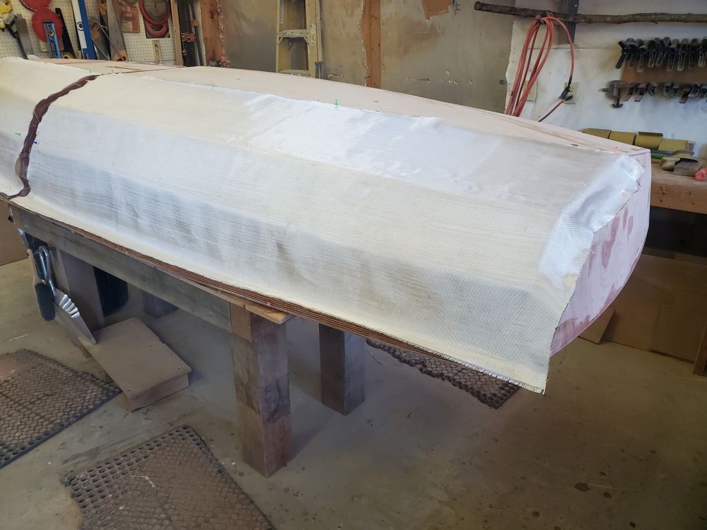
Because the hull sheathing required epoxy fill-coating on the same day, to ensure the best of bonds between the fiberglass and the second coating, I planned to start the actual fiberglass process in the morning, so that gave me the rest of the afternoon to cut all the fiberglass required and get things set up. The manual called for cutting four pieces of 6 oz. cloth 25-1/2″ wide and six feet long by cutting the full cloth width in half, but I found that the roll of cloth was only 50″ wide, making this a mathematical impossibility. There certainly wasn’t enough cloth to cut the required widths and discarding the not-quite half left over, but fortunately I found that 24″ width was just enough to cover the boat as required; these sections of cloth extended from about an inch over the bottom hull panel to the edges of the gunwales. I did some rough measurements on the boat first before committing to cutting the four pieces of cloth, just to be sure.
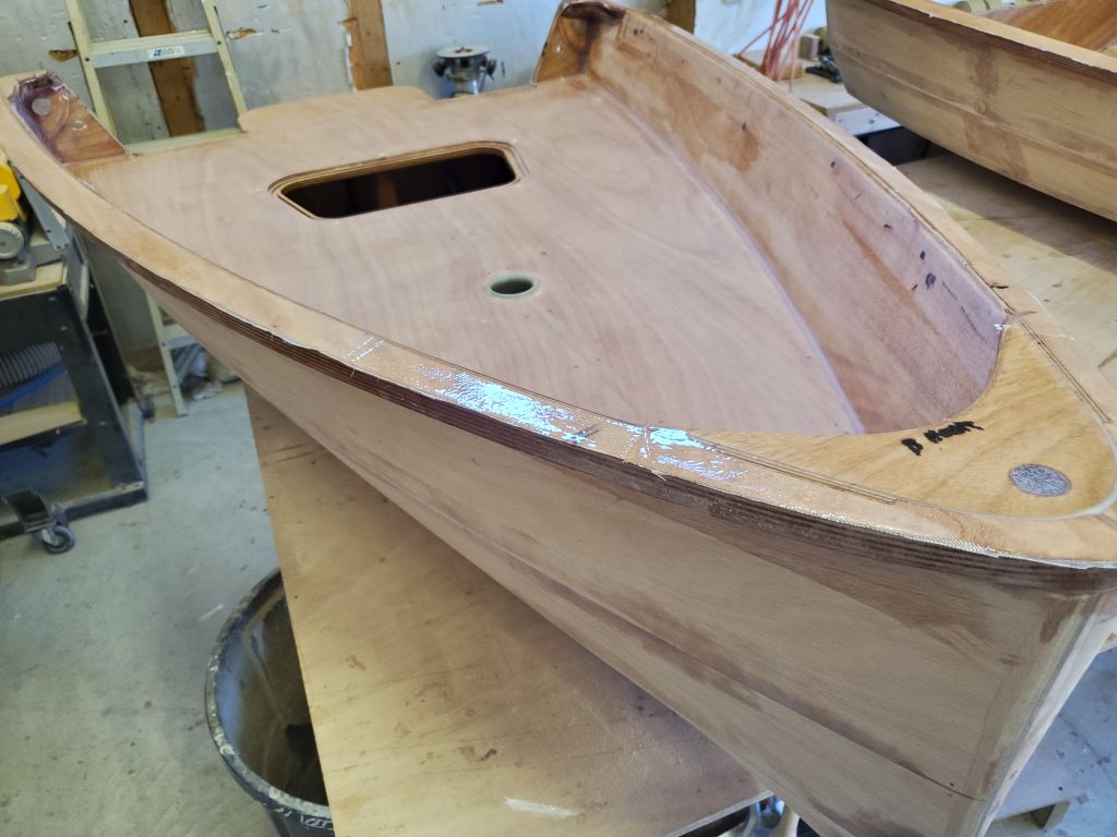
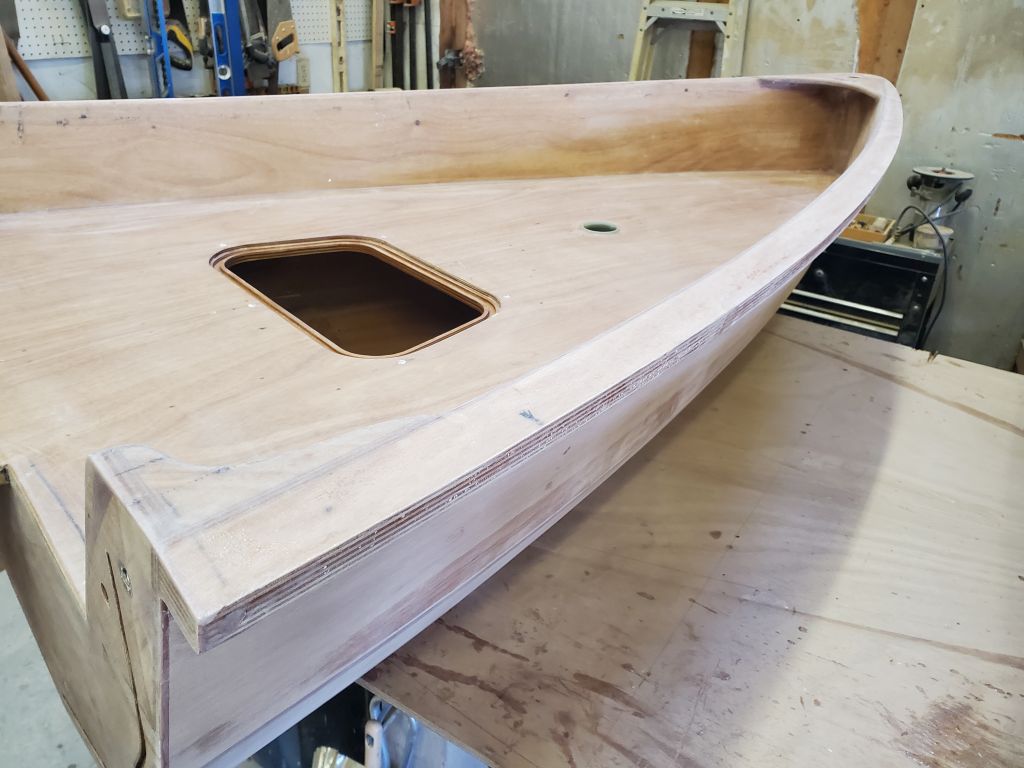
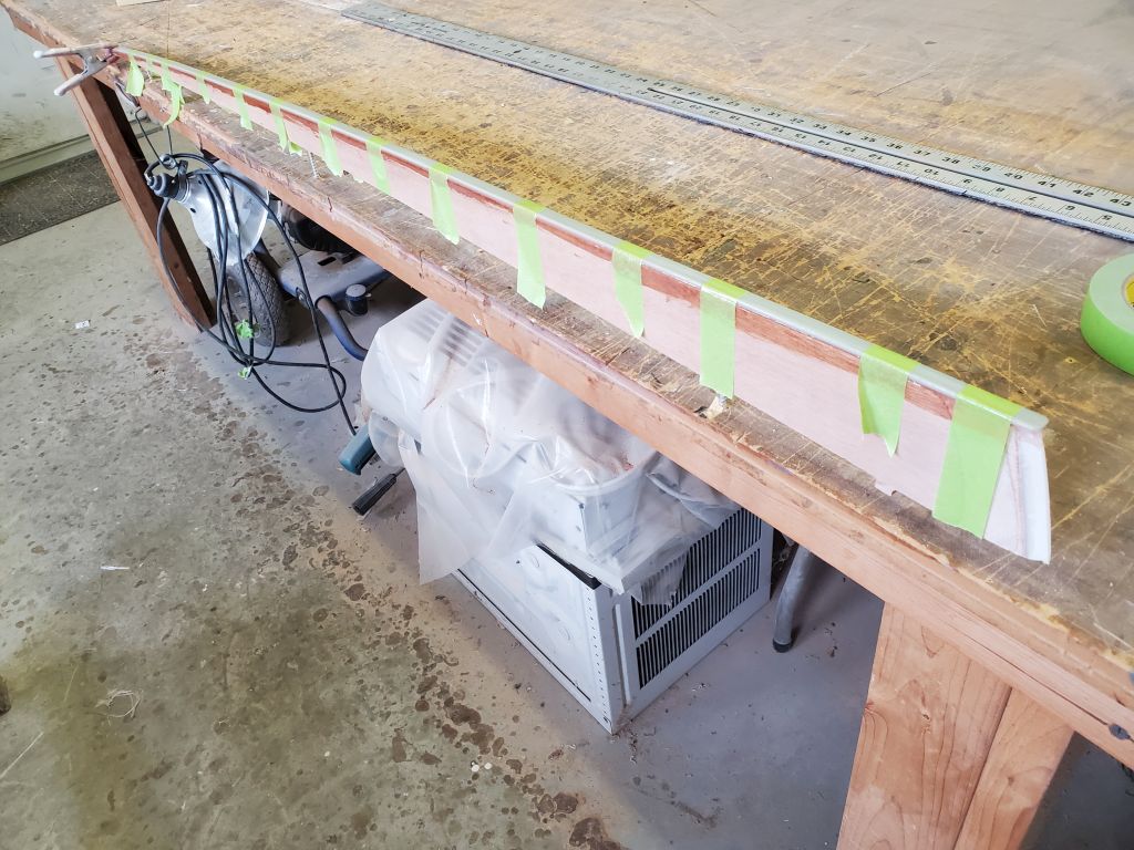
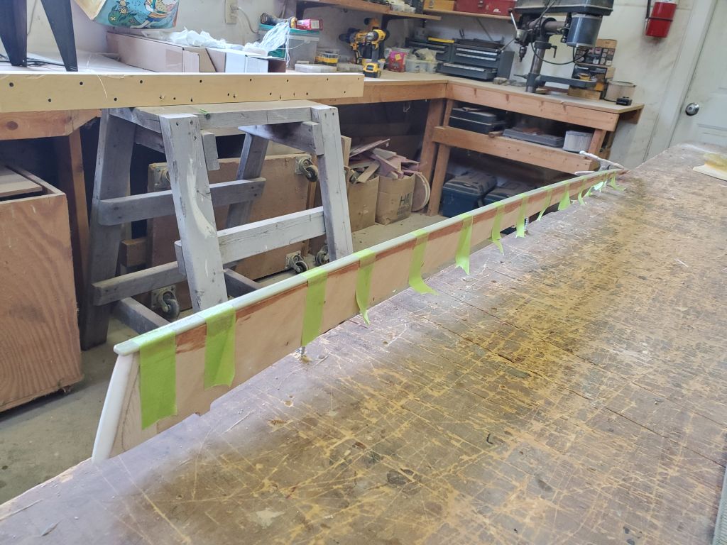
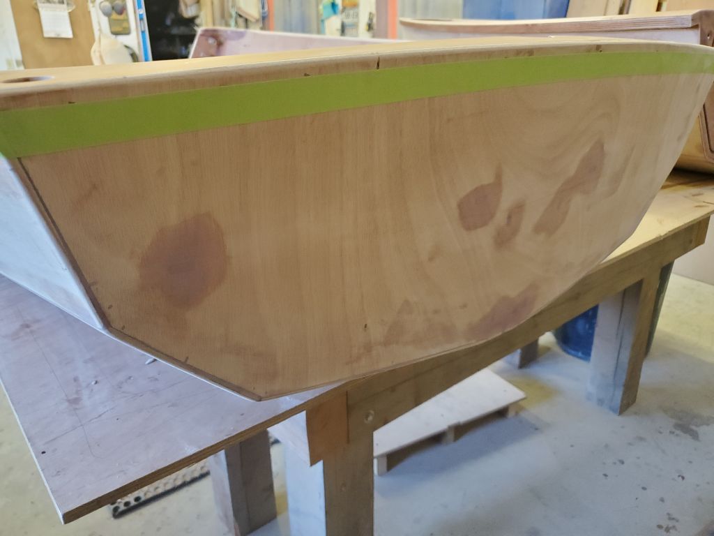
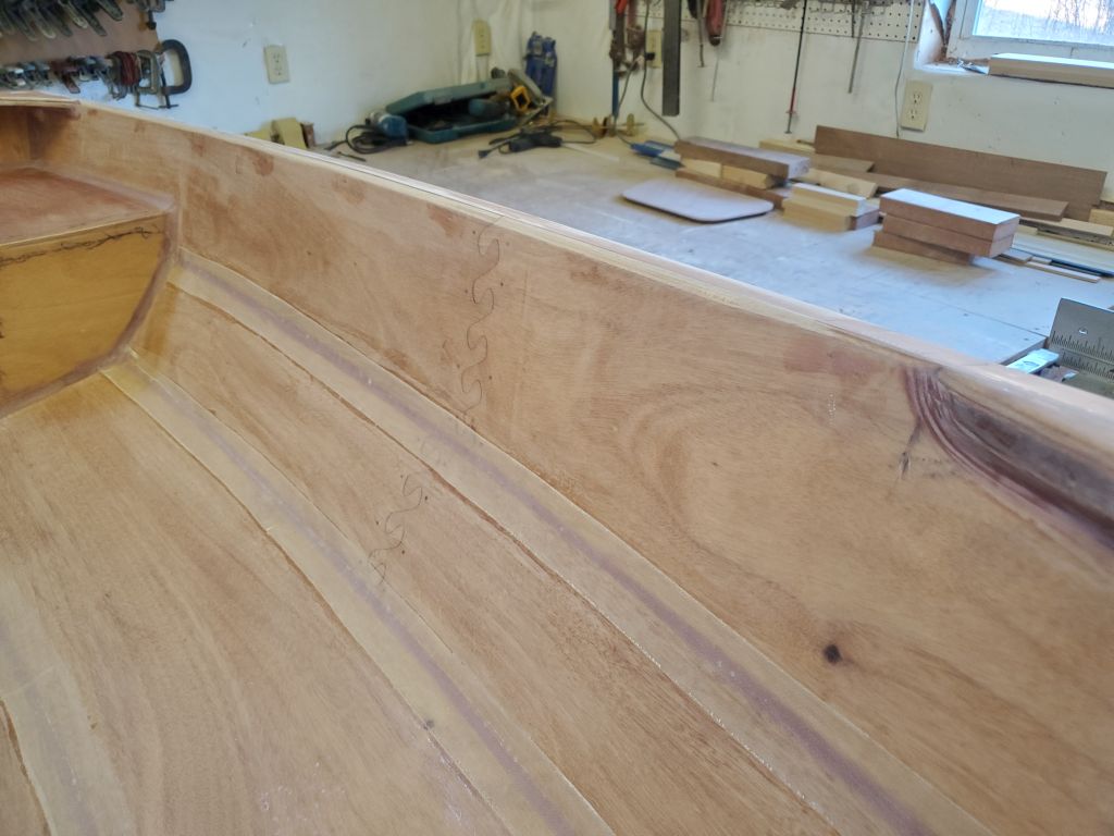
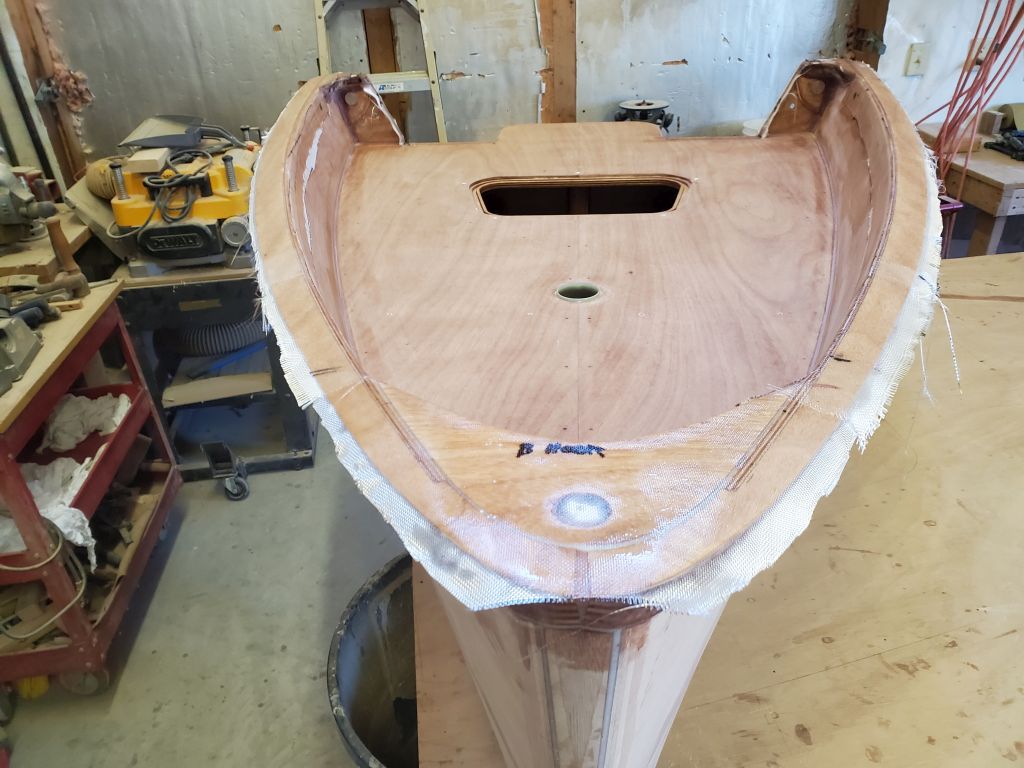
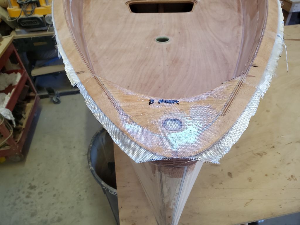
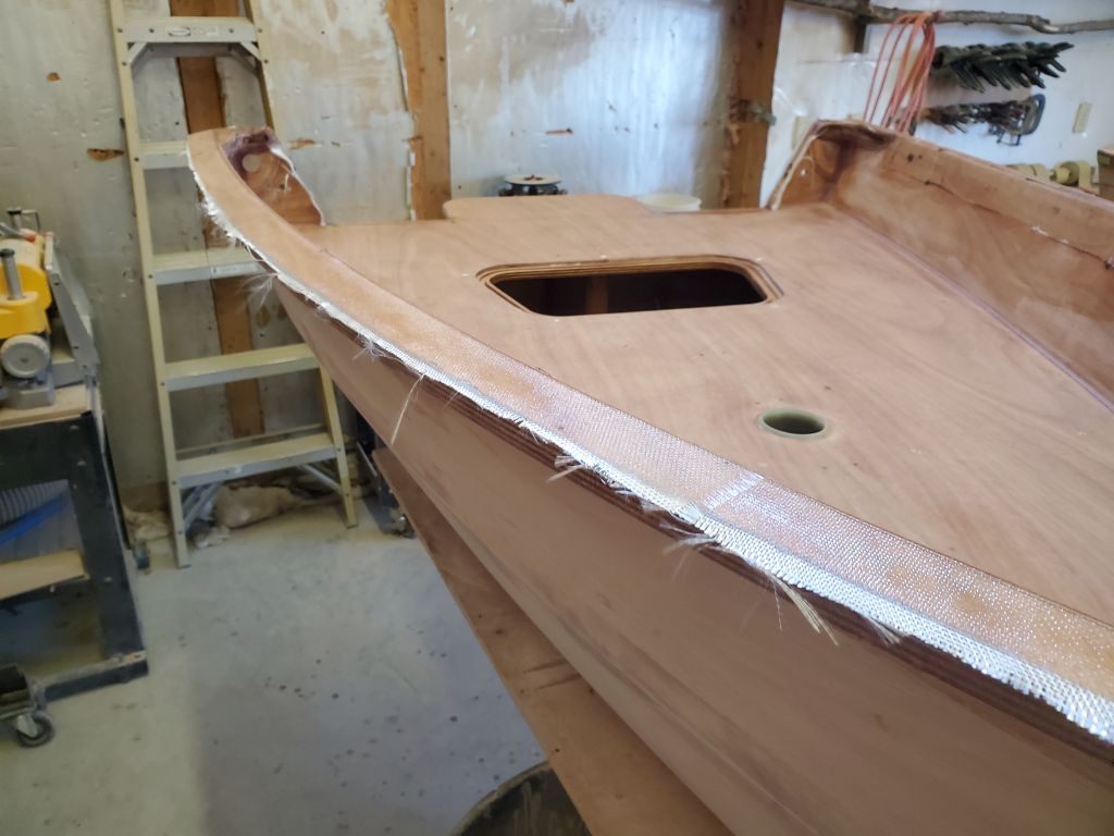
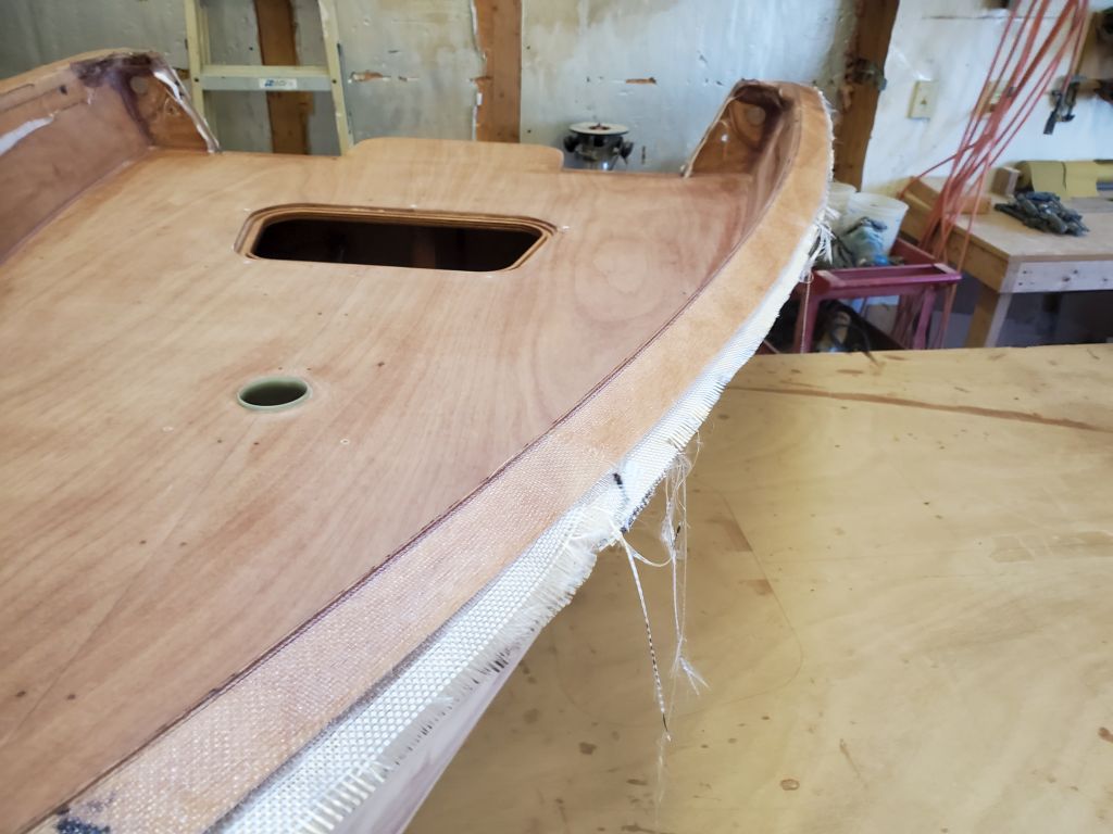
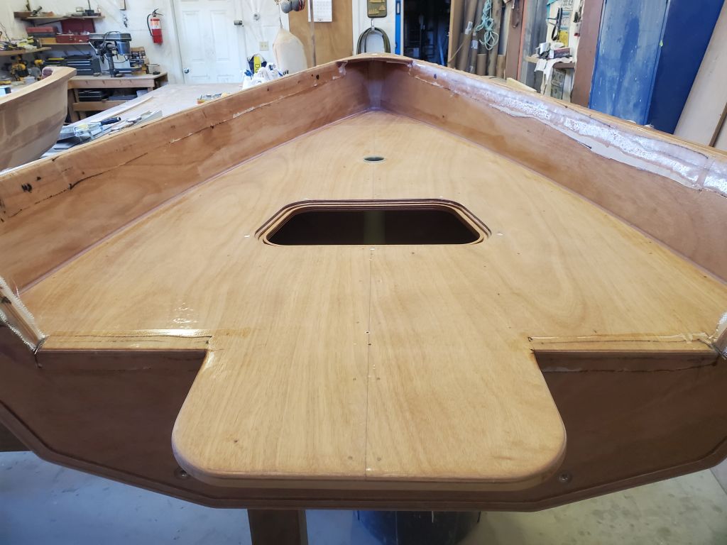
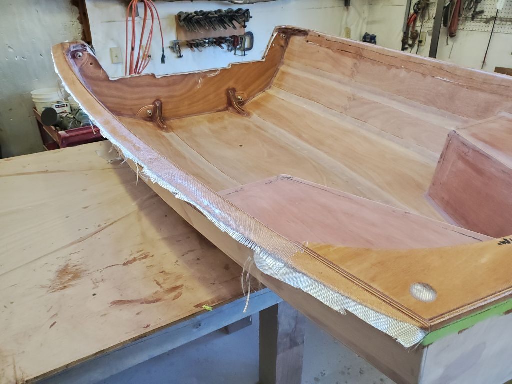
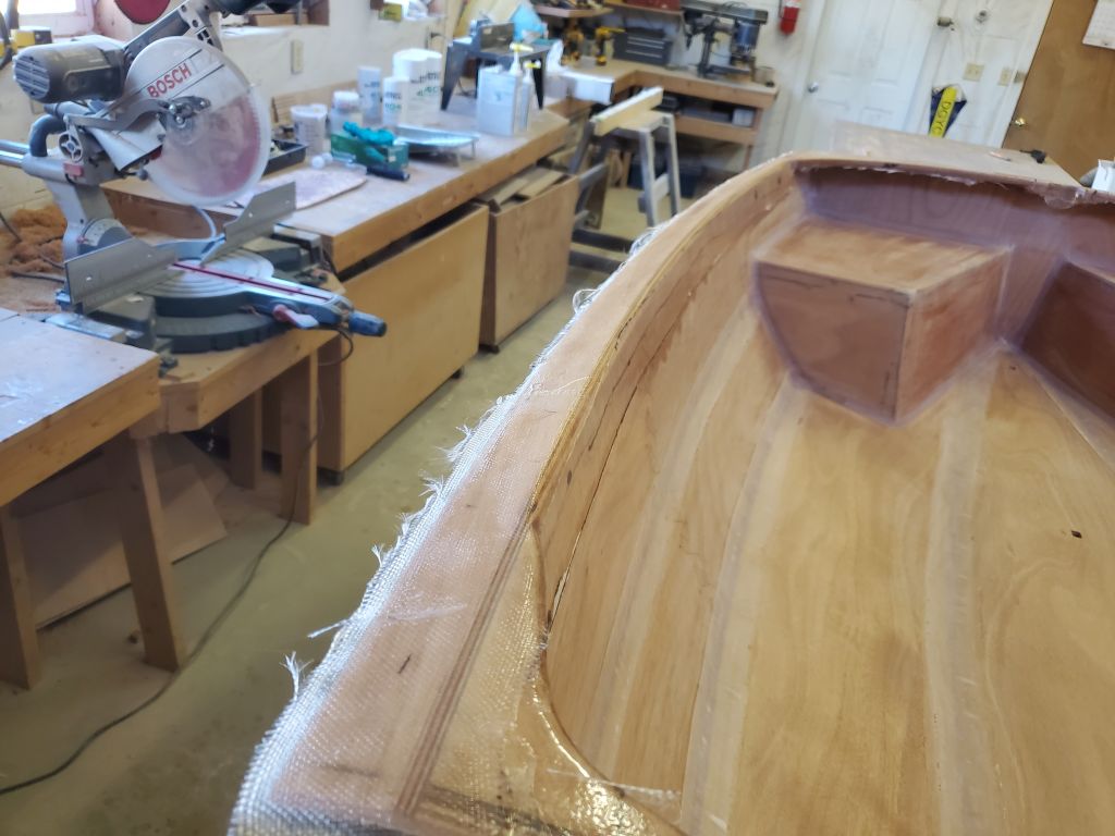
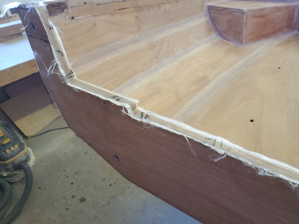
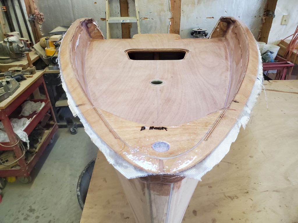
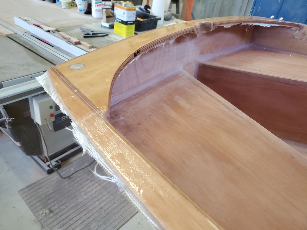
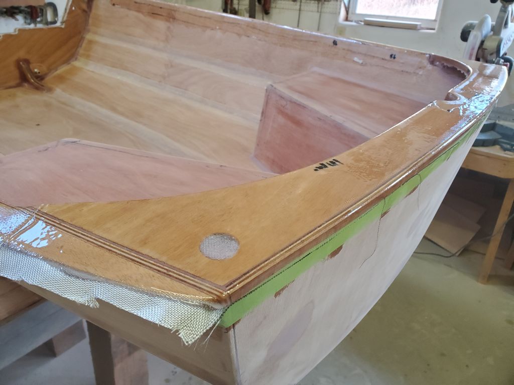
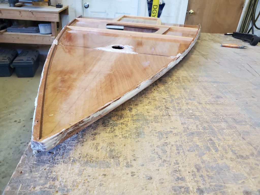
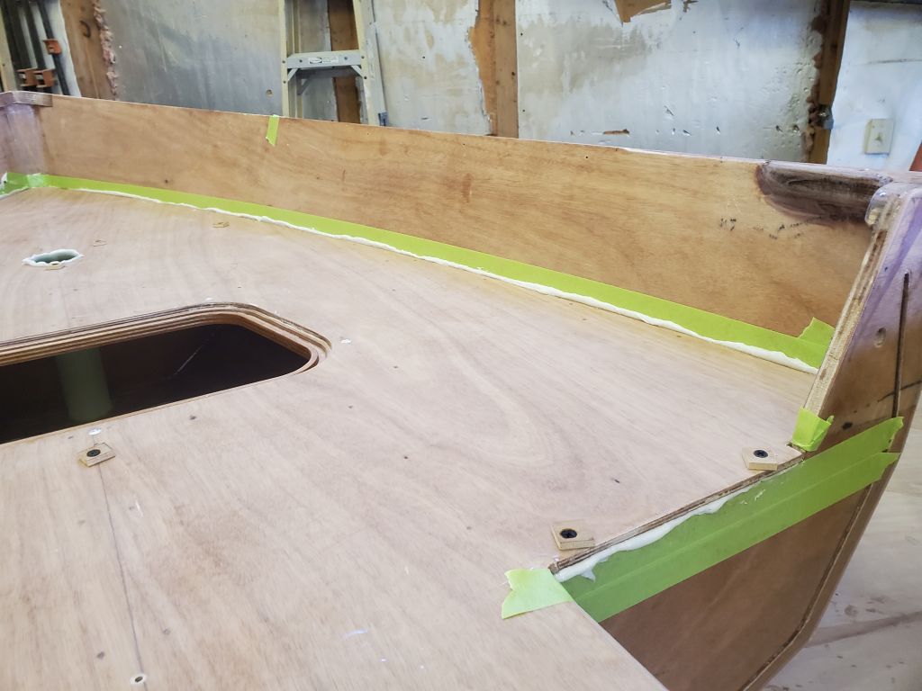
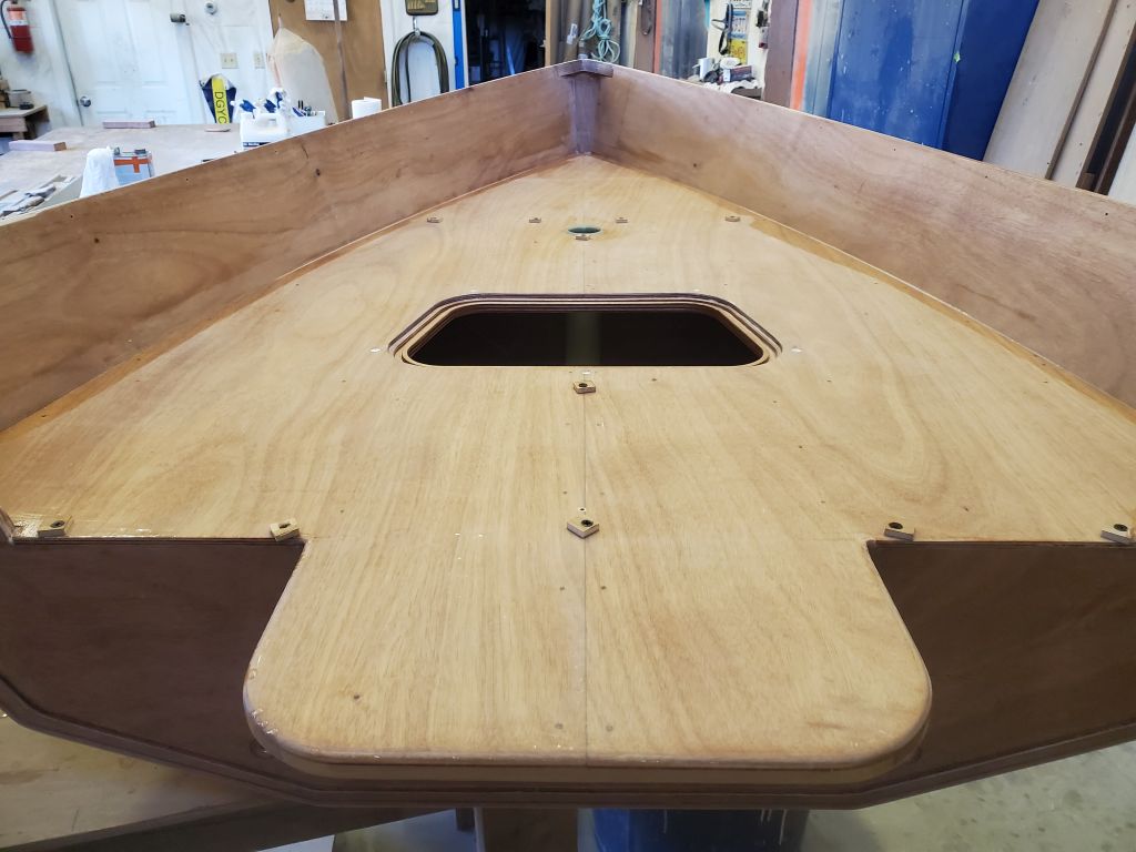
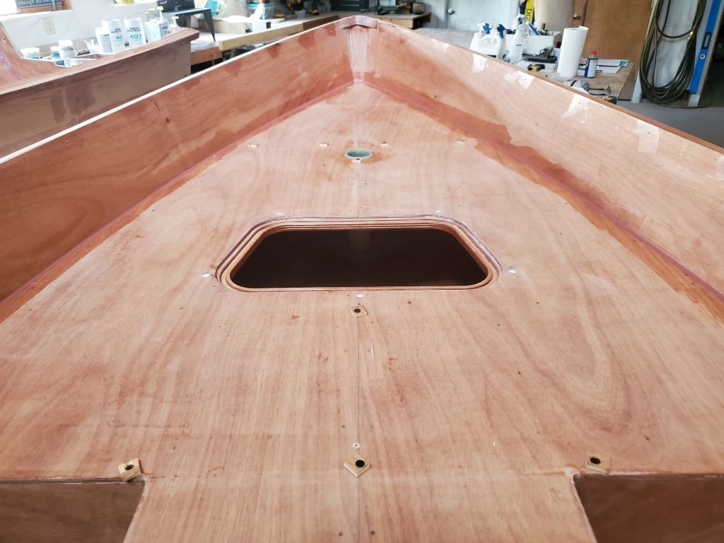
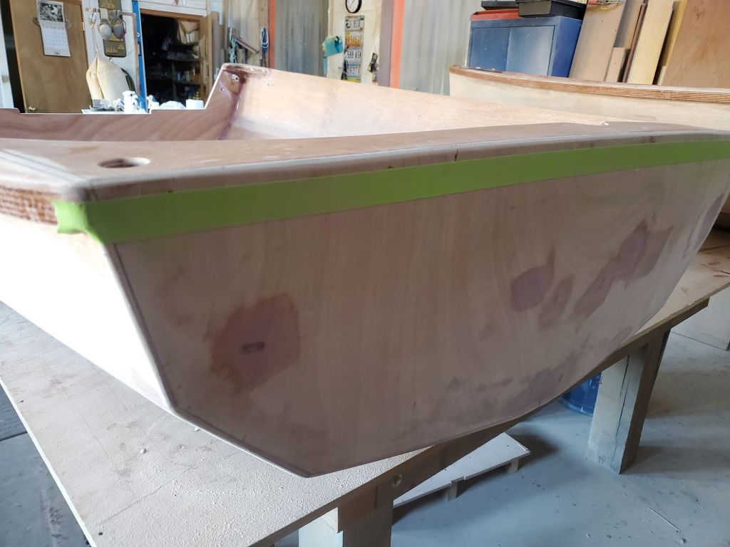
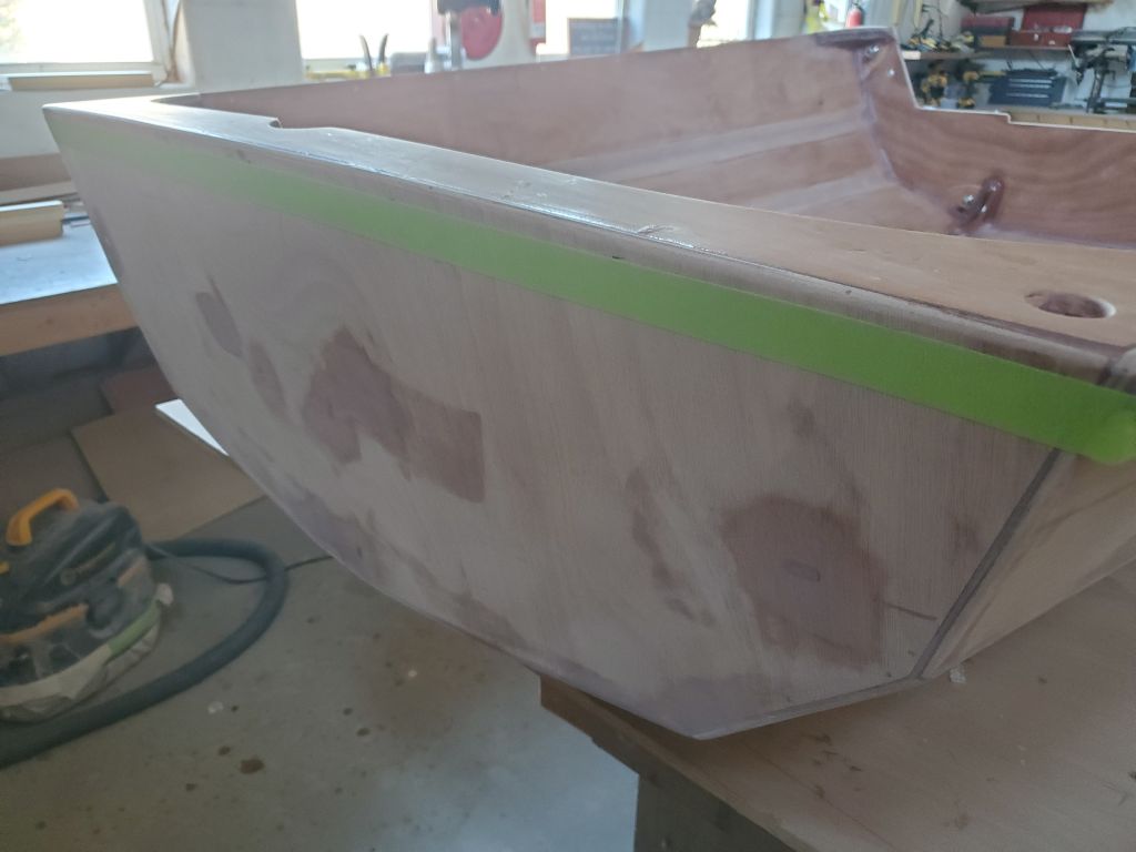
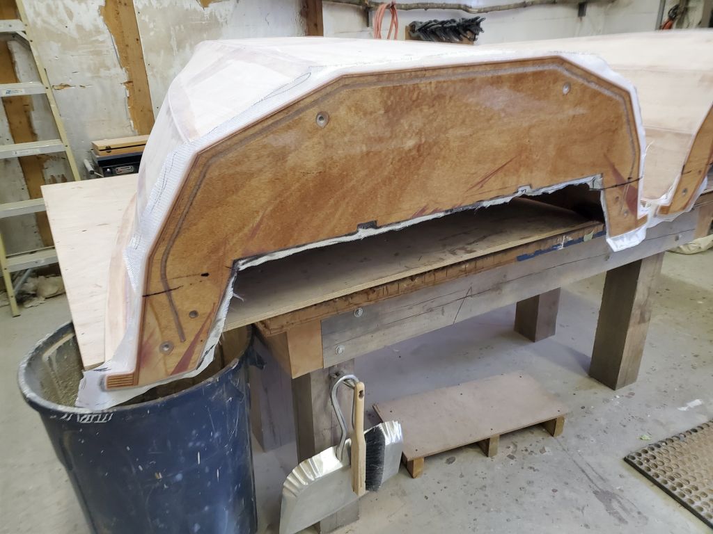
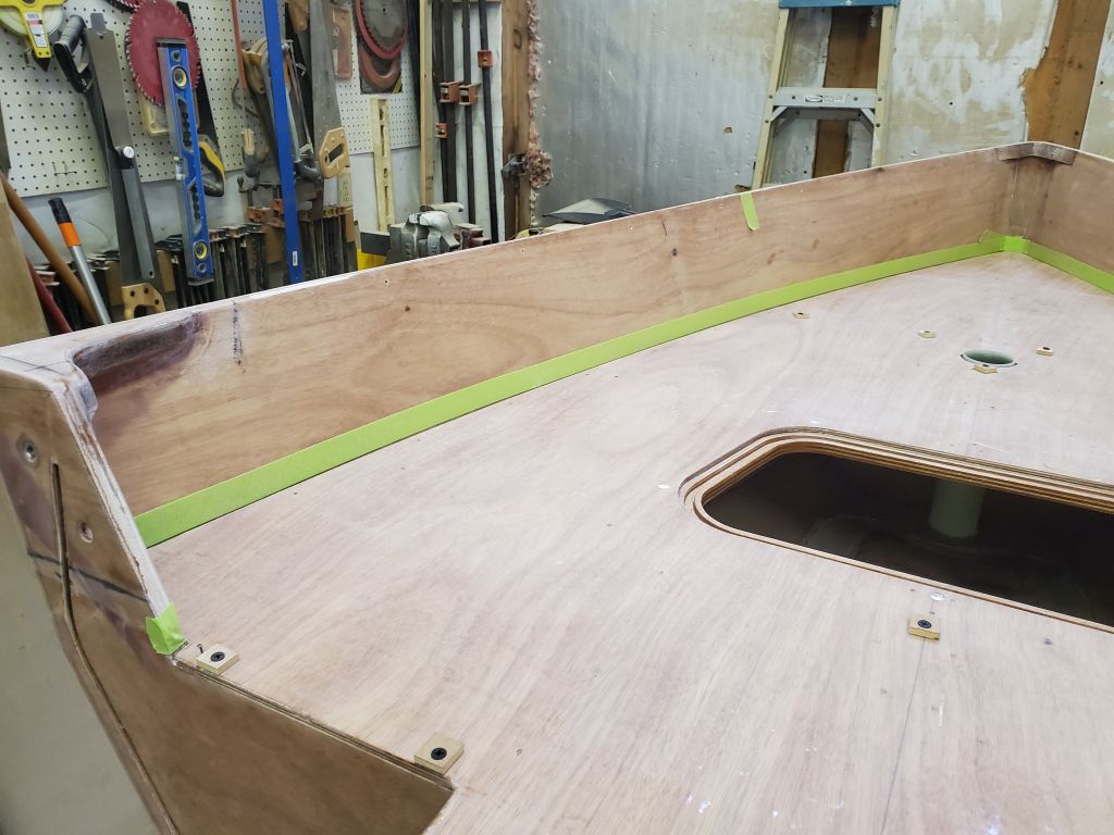
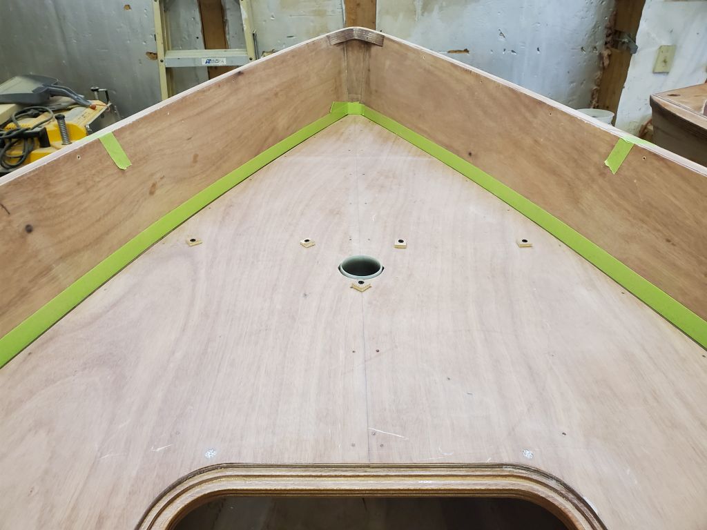
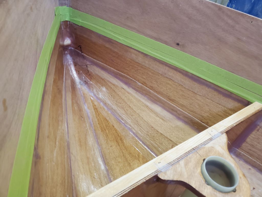
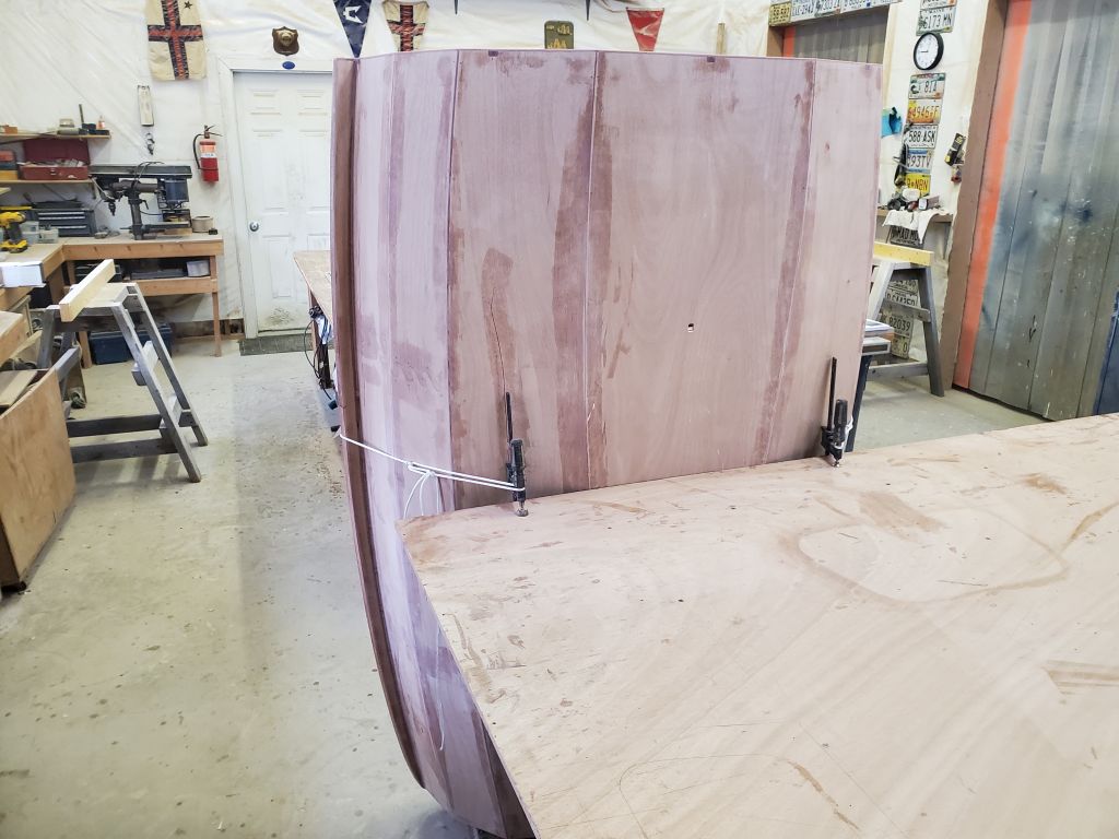
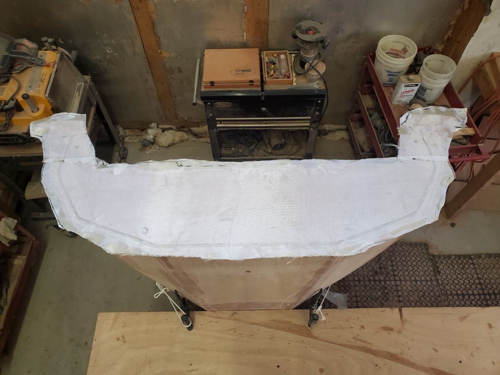
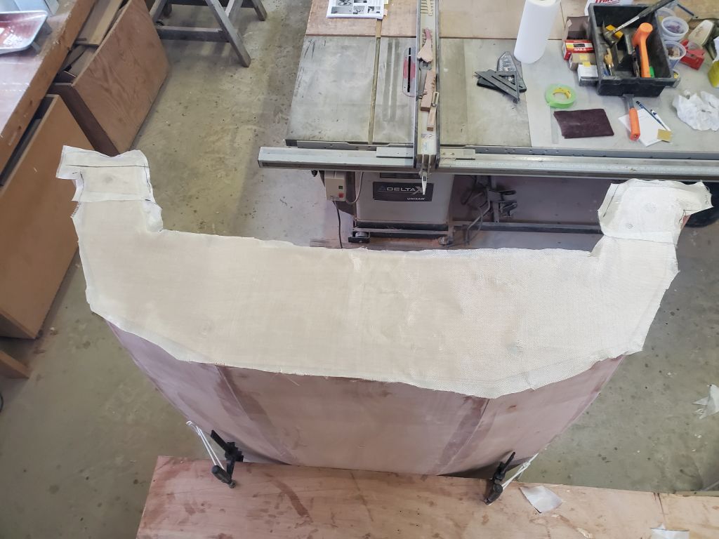
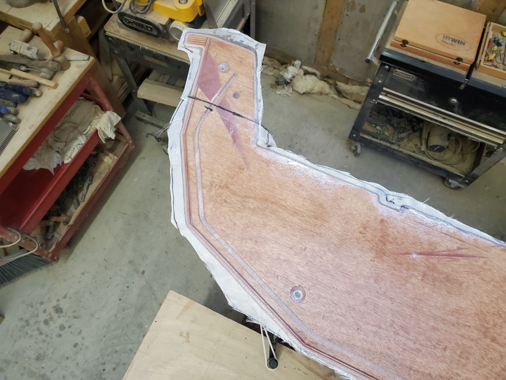
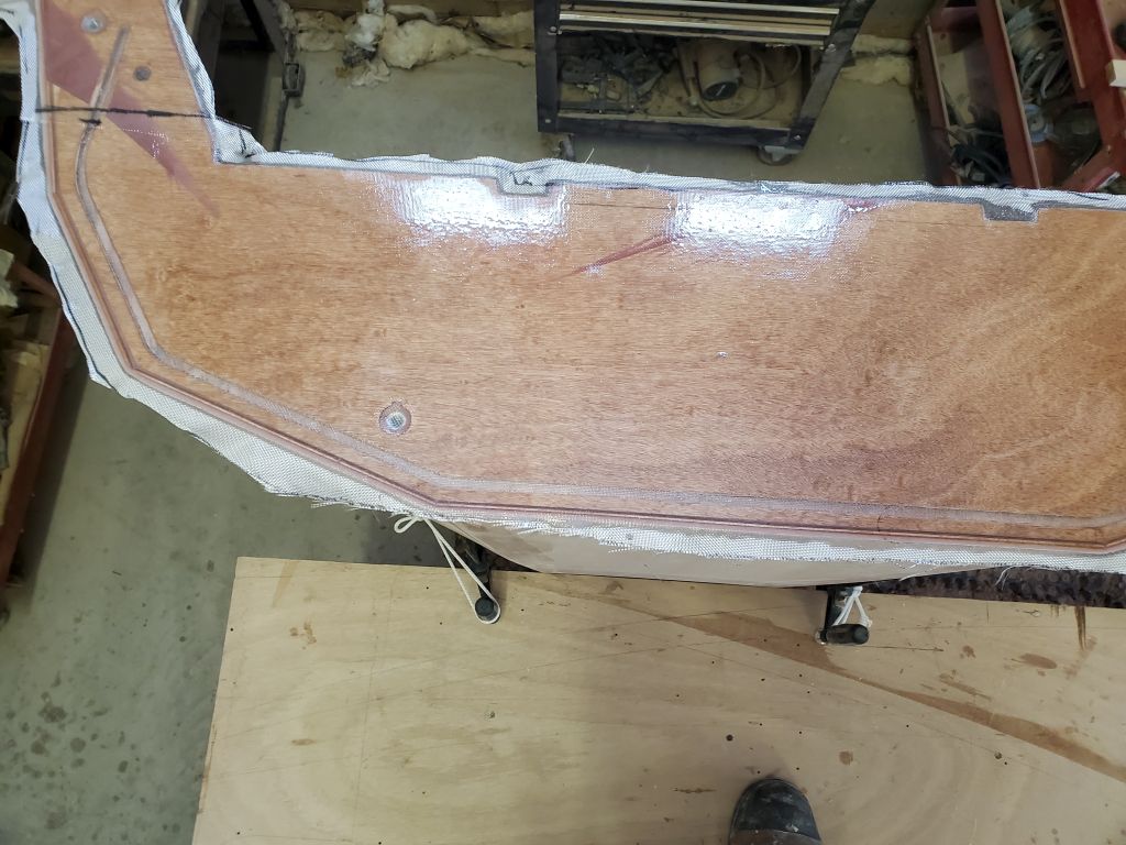
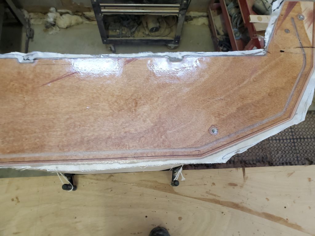
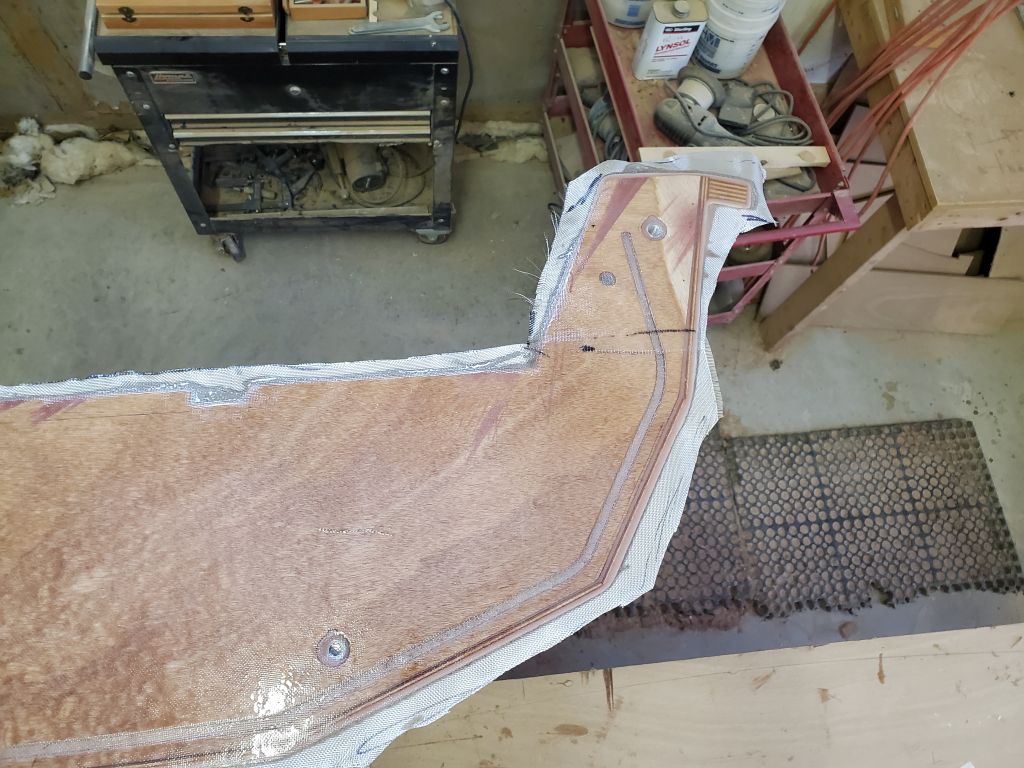
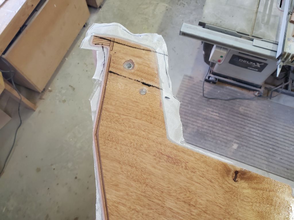
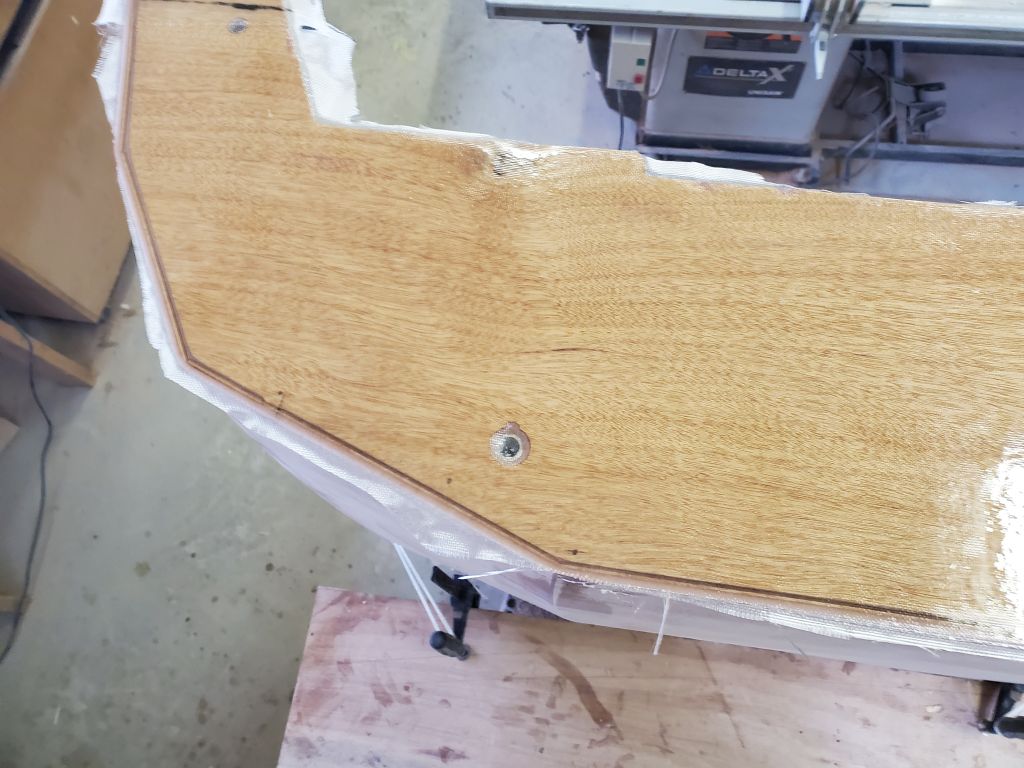
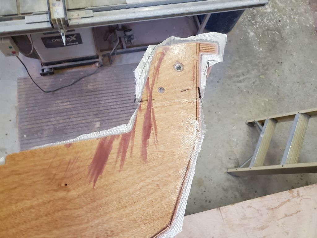
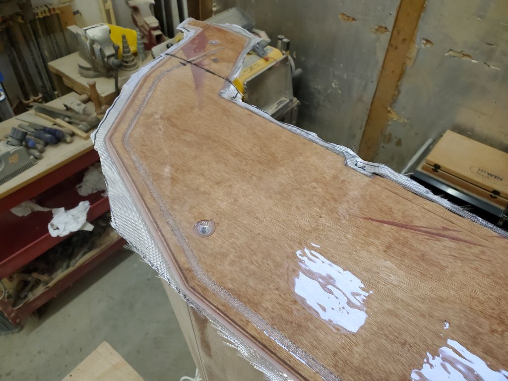
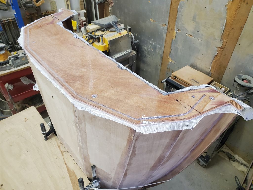
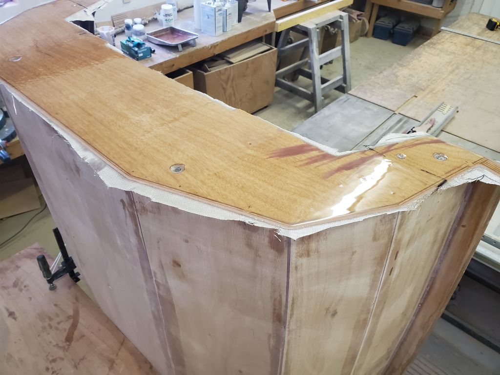
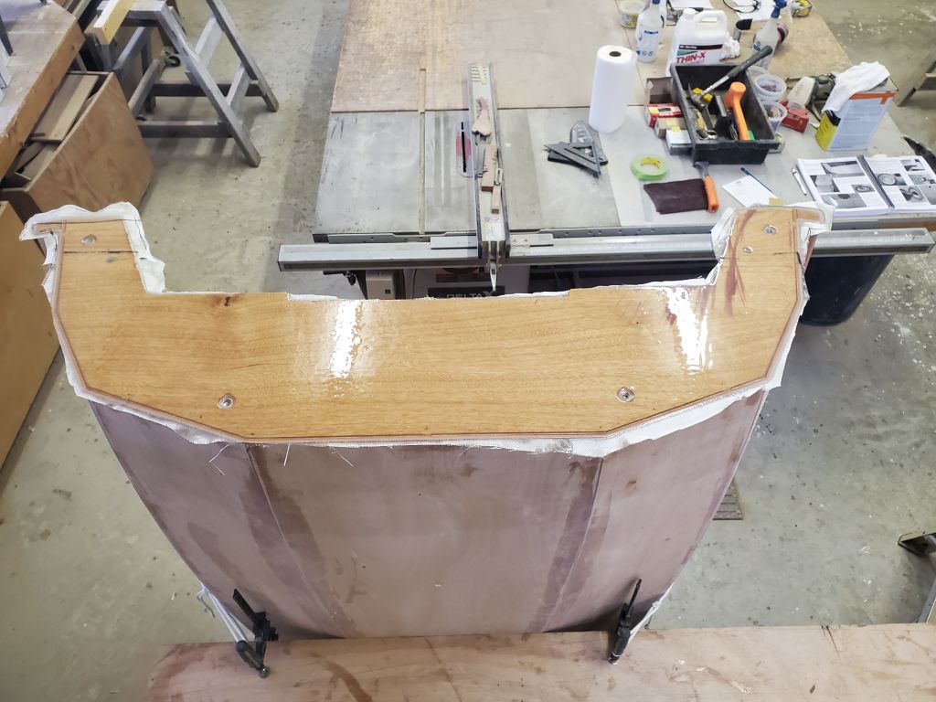
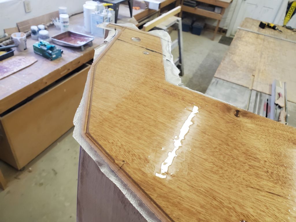
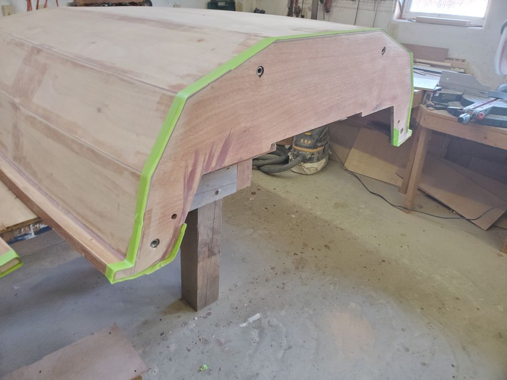
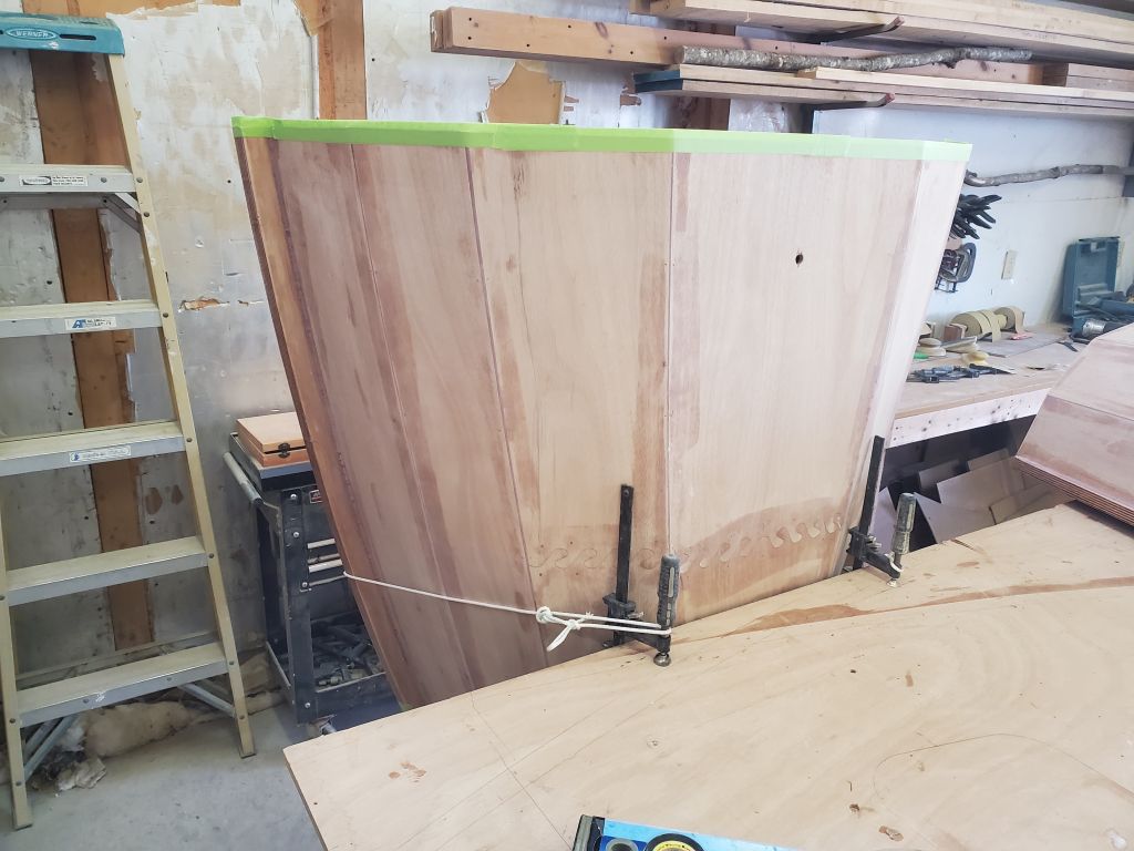
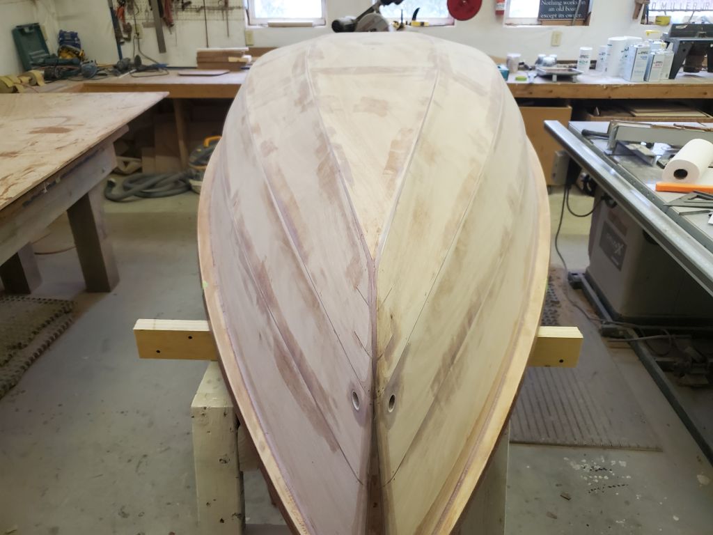
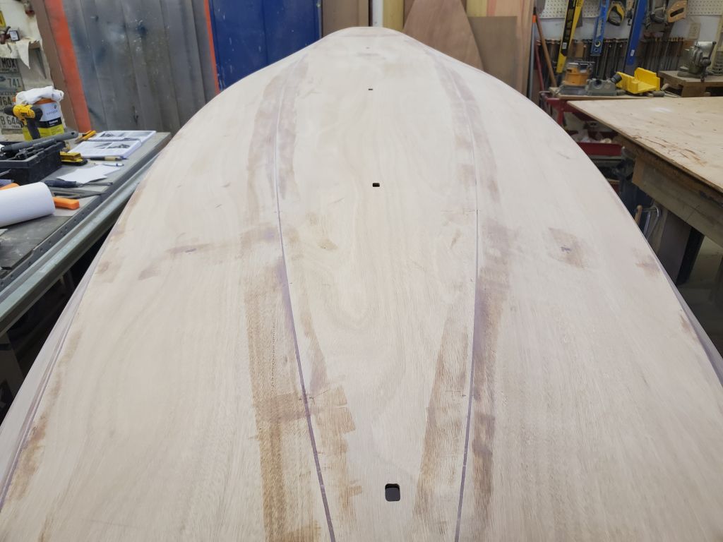
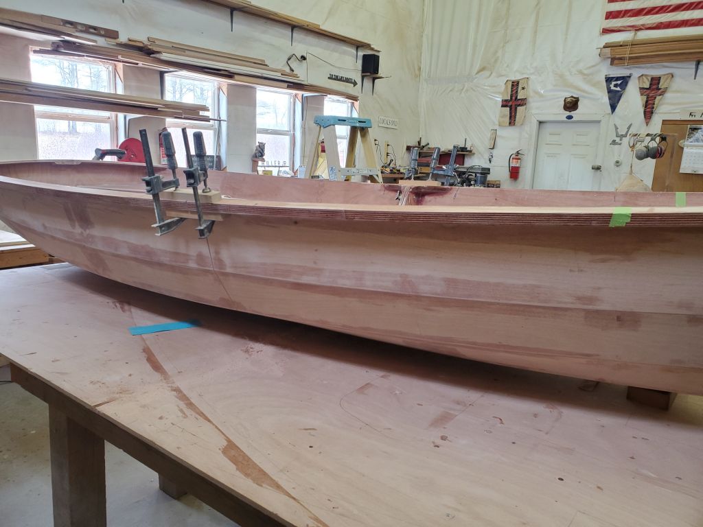
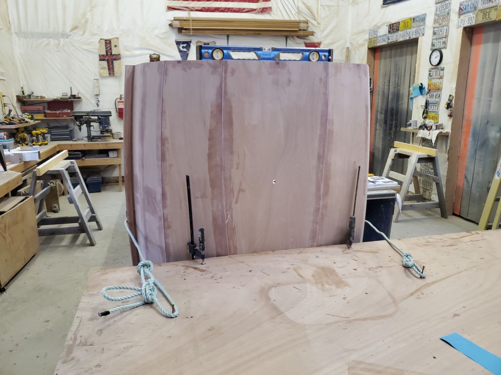
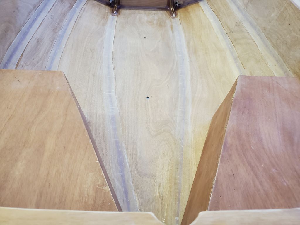
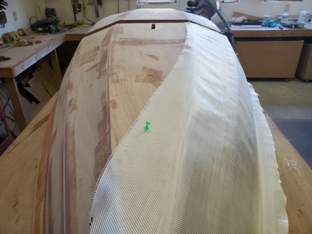
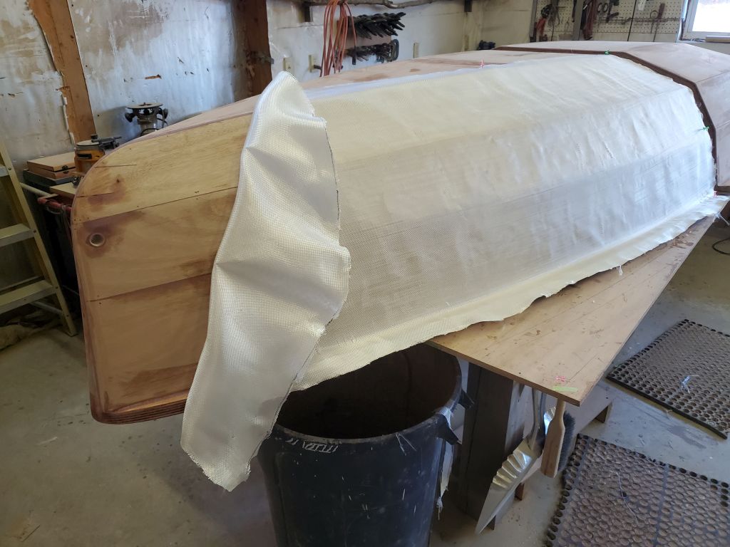
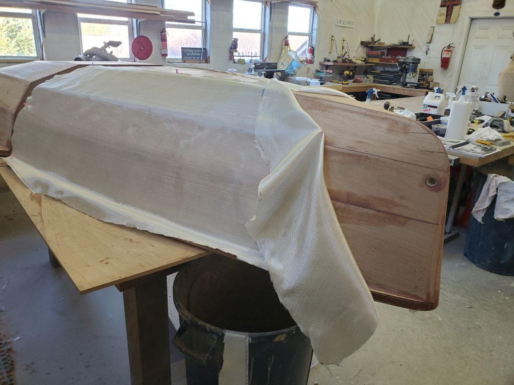
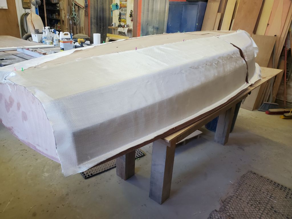
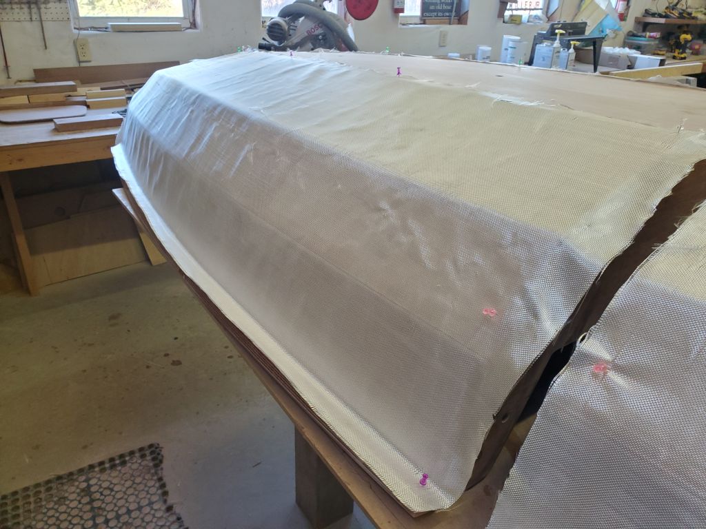
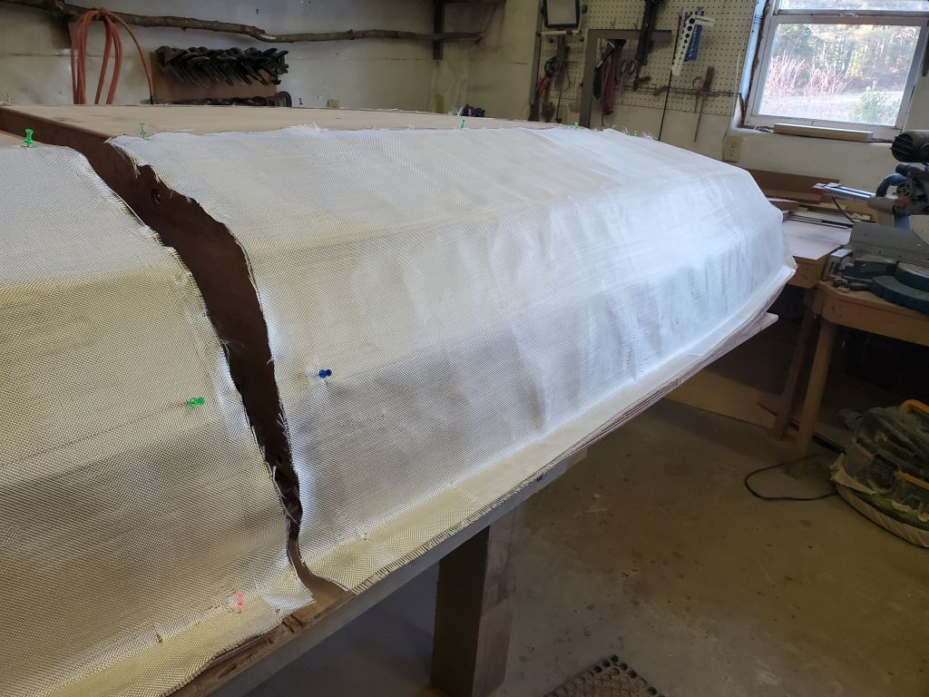
I started by laying the panels out on the forward half of the boat, which was a bit more involved because of the narrow stem. I laid the cloth dry as directed, and used several push pins to help hold it temporarily. At the stem itself, the cloth would wrap around slightly to the other side, and I trimmed it as needed before folding the cloth back on itself and with additional push pins to hold it. Then, I repeated the layout on the opposite side.
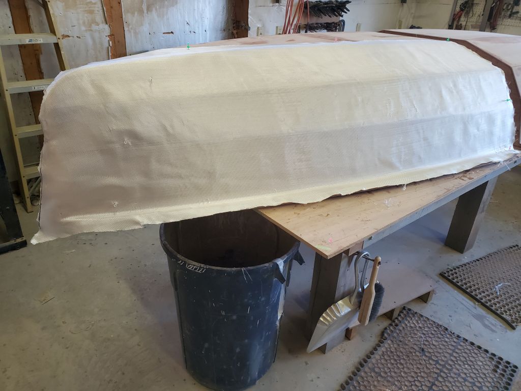
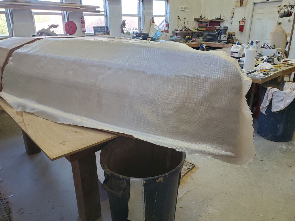
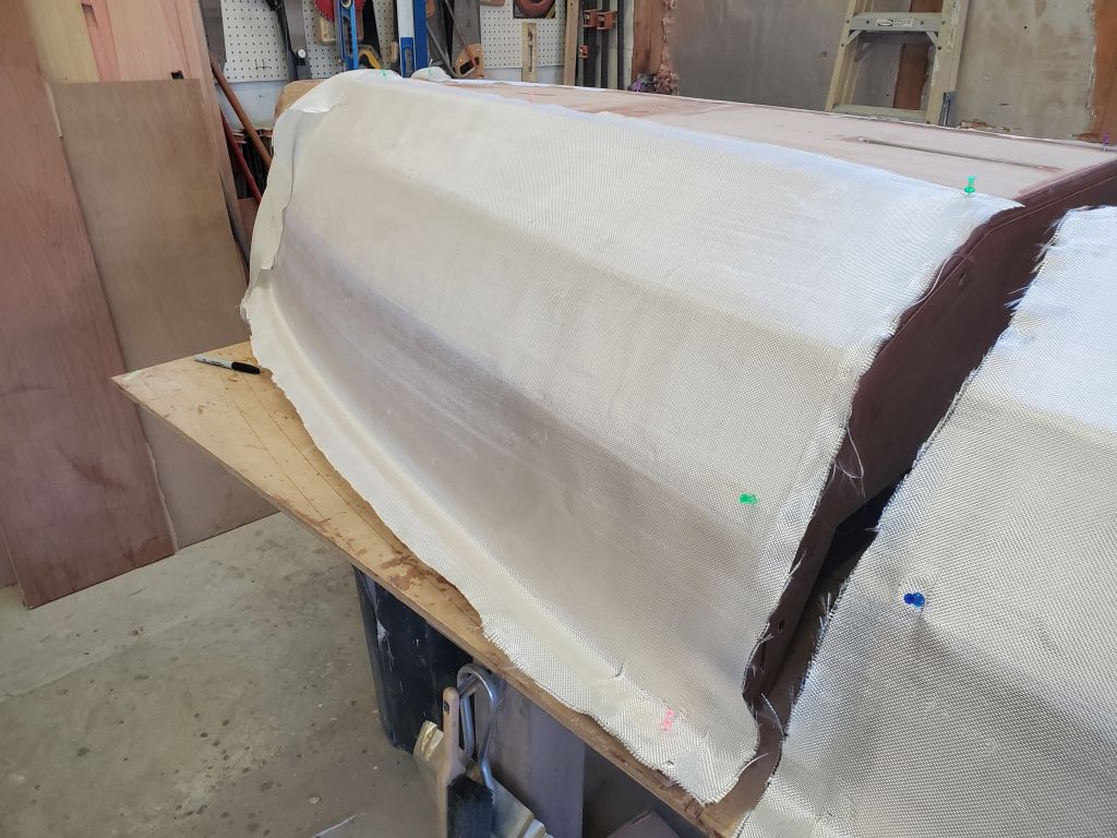
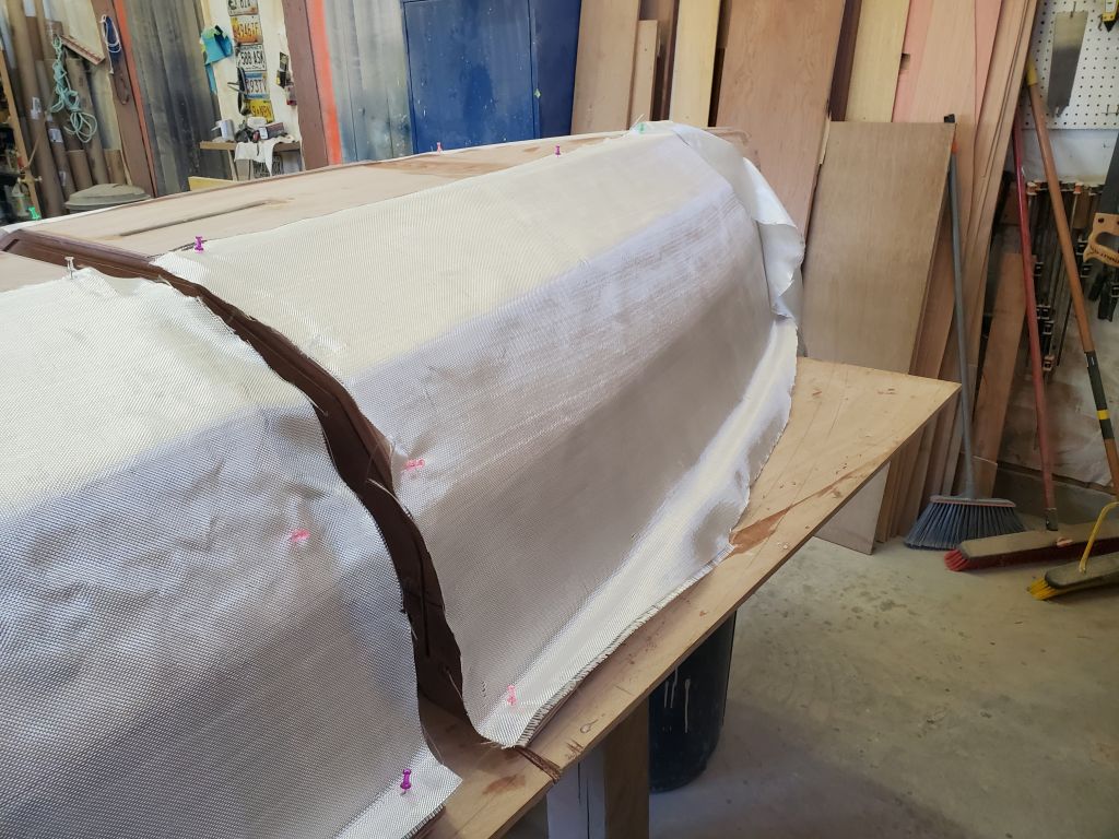
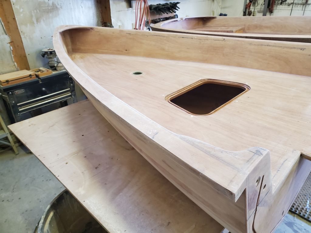
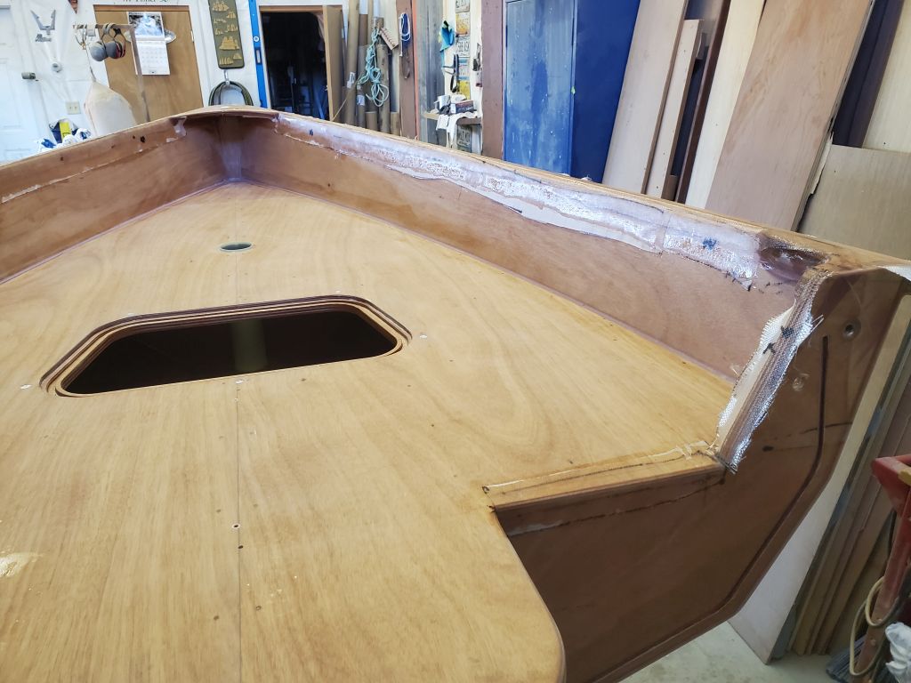
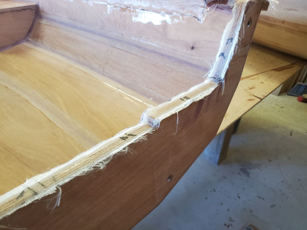
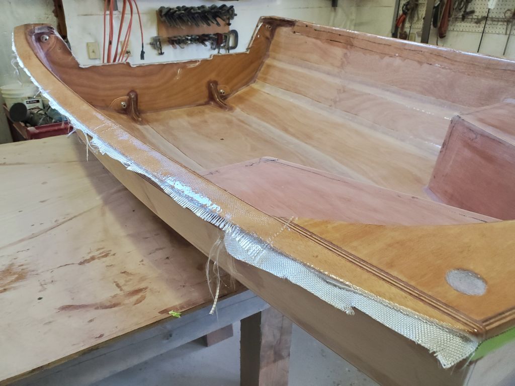
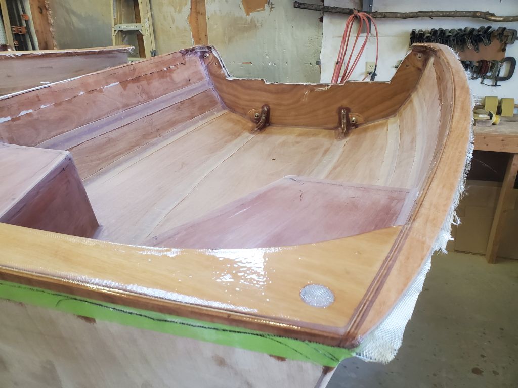
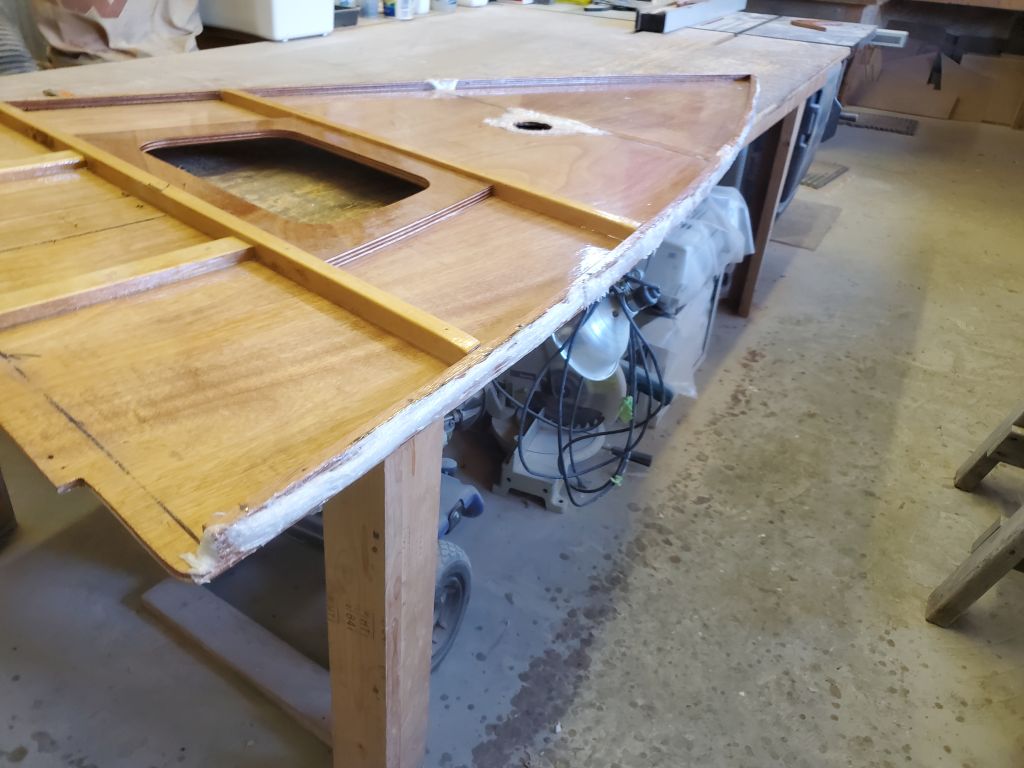
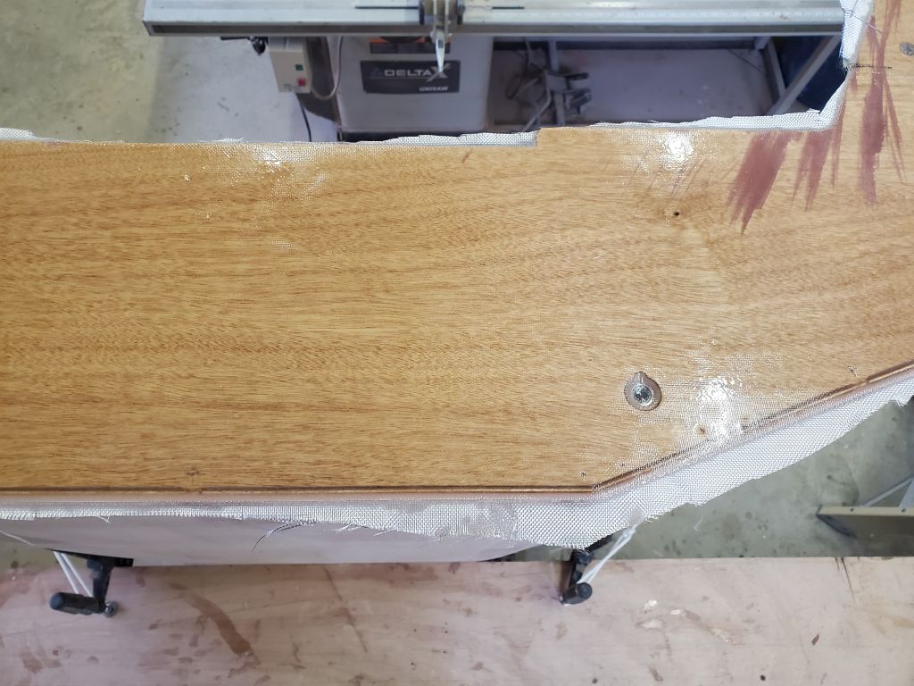
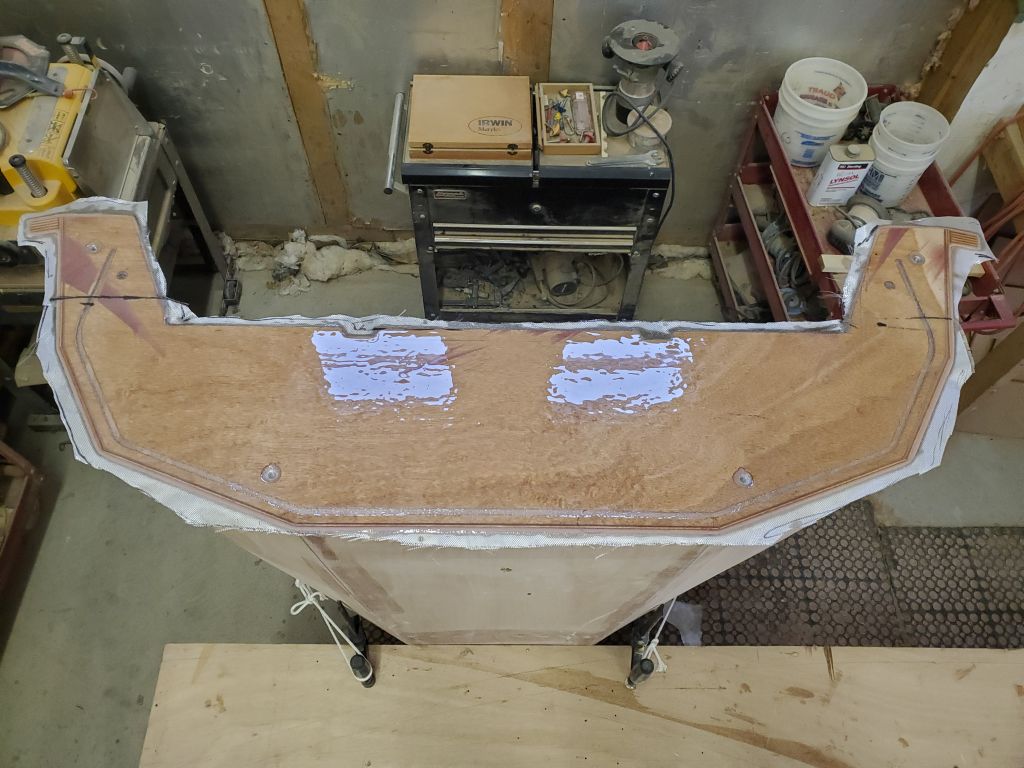
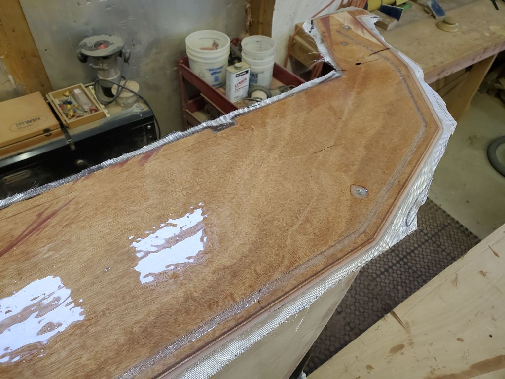
The stern half was more straightforward, but given the minimal width of cloth available, I found that it was only just barely wide enough at the widest part of the boat to extend both 1″ on to the bottom panel, and over the entire bottom side of the gunwales as required. But it was enough. Just. Again, I used temporary push pins as needed to secure the cloth for now. I left the ends to run wild over the center and transom.
The fiberglassing would take place over two days, and two separate operations, to allow the bottom panels to be installed as intended, so the four sections needed for the first day were all set to go. To prepare ahead, I cut the fiberglass required for the bottom panel on each half of the boat: a piece of 6 oz, plus a second layer of 4 oz. to give extra impact and wear protection to the bottom of the boat where it would be needed most in practice. Cutting the two pieces of 4 oz. used up the rest of the roll provided, and this didn’t leave me enough 4 oz. cloth for the required transom piece, so I cut that out of 6 oz. instead. This shortage probably happened because earlier for some small part or another I’d had to cut fresh 4 oz. cloth to fit when the instructions called for using scrap–but I’d no scrap that fit at that time. And I didn’t even use the 4 oz. cloth for the interior chine tabbing, as the directions had called for; that would have left things even more short.
My only real complaint with the contents of this otherwise excellent boat kit is that the amounts of material are a bit sparse or otherwise insufficient, and allow no room for error, variations in how one cuts or uses things, or anything else at all. I ran out of copper wire when I wired the hull and had to buy more, and now I was out of one of the weights of fiberglass, which would probably domino into eventually running short on the 6 oz. cloth somewhere later in the process because I had to steal some now for the transom.
But that was a problem for Future Me. For now, I was ready to get the hull glassed starting in the morning.