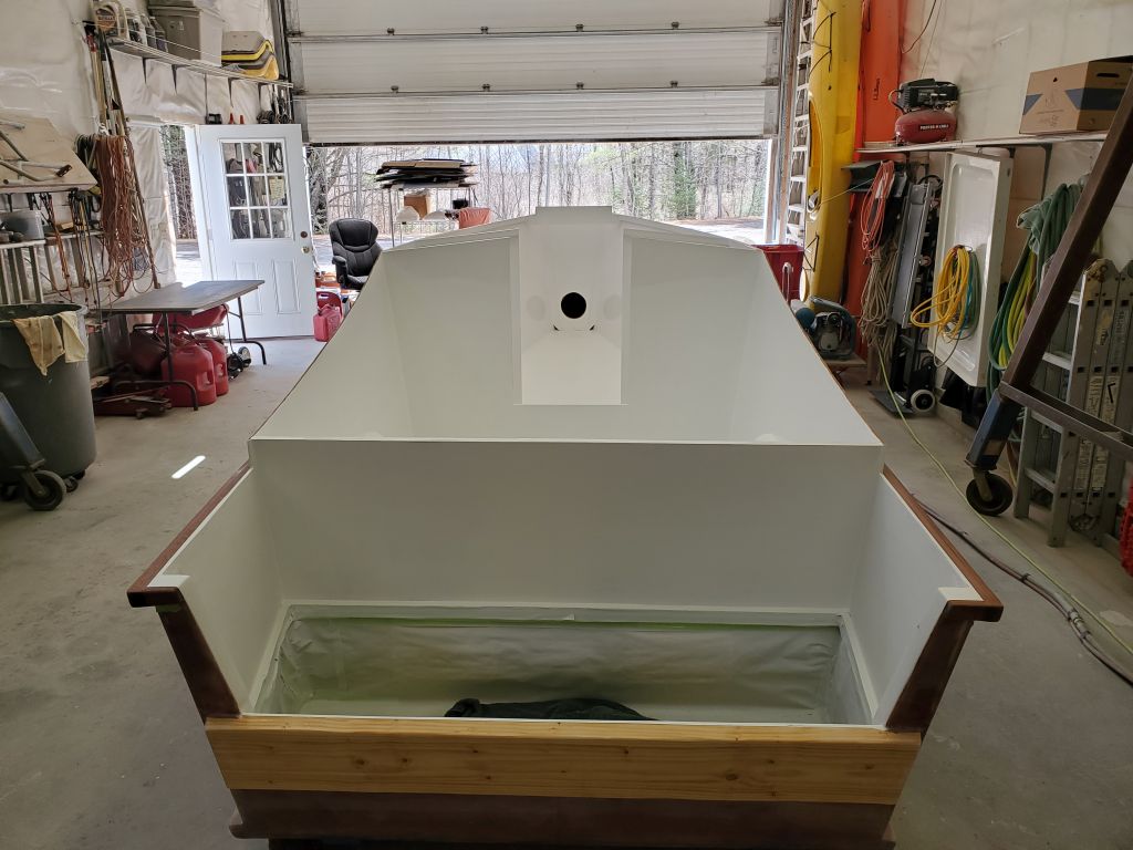
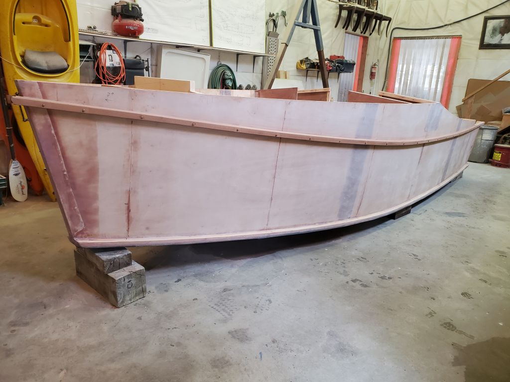
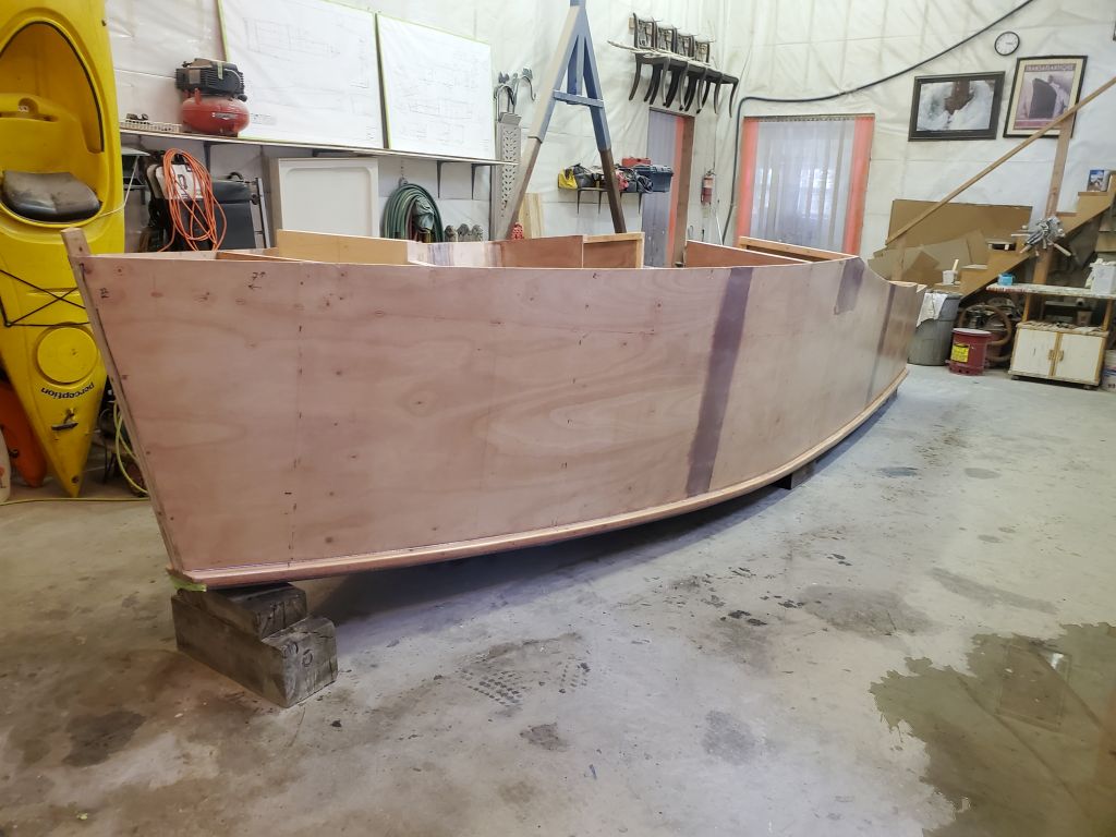
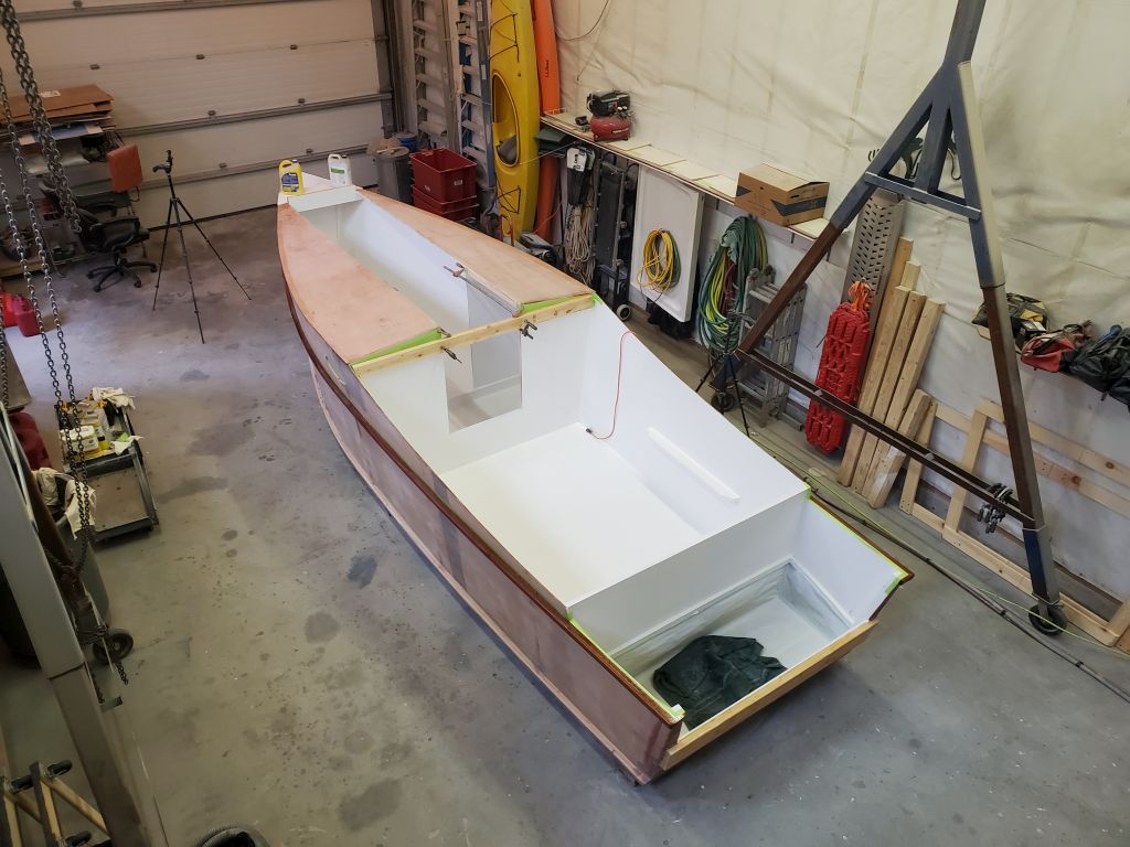
Episode 3 is now live. This details work performed December 4-6, 2025. Total project hours to date as of this video: 16.75 (including some work not yet shown)
Episode 2 is now live. This video includes work done between November 25-27, 2025. Total hours to date: 8
The saying goes that man plans, and God laughs. Adapting to changes in circumstance is challenging to some, but to others it offers new challenges and opportunities to be absorbed.
And so it was that in early 2022, I was fortunate to inherit a rundown but otherwise desirable waterfront property in Virginia from my uncle.
(Bear with me, the background is relevant here.)
This shakeup in circumstance forced some other changes, but my wife and I happily adapted and made changes, sold another property we’d owned for 13 years, and spent as much time as we could over the past few years working on our new property, restoring the overgrown wasteland of the property to something more open and attractive, and disposing of 13 huge dumpsters’ worth of accumulated hoard from the house and land in the process, while restoring and otherwise improving the small 1940s era concrete house to livable and even (dare I say) cute condition. We built a new dock to replace the derelict original, but there was no time for boats.
Till now.
With the house situated on a protected creek shooting off another, larger creek leading to Chesapeake Bay itself–all perfect for casual exploring and sightseeing–we knew the time would come for a boat, but what kind of boat? Our spot isn’t navigable by deep draft boats–and I had no desire for a cruising sailboat or larger powerboat anyway–so clearly it’d be a small runabout of one form or another.
But one thing I knew for sure: I didn’t want some old boat with a massive outboard and all its inherent problems, and couldn’t afford anything with a new outboard. Plus, waters are shallow where we are, with shifting channels, and something small and shallow was the best way to go.
Enter the AF4. Not the most descriptively-named design, but after a friend told me about it, I learned that it might well be something good for us. This little boat, designed by Jim Michalak–a sort of George Buehler for affordable trailer boats–had a lot going for it–practicality, low construction cost and most importantly it only needed a small outboard, something that the budget could probably handle.
So here we are. I’m building a 21-foot version of this boat, specifically called the AF4 Grande, or AF4-G for short. Rolls right off the tongue, doesn’t it.
My thinking now is that this will be a video-only project, but we’ll see. I wanted there to be some sort of background first, though.
In any event, here is the first video on this build. If you find this interesting, please check out the future updates on YouTube.
Now with the epoxy cured overnight, I was ready for the final anchor roller installation. I lined up the roller assembly and support block, and dropped in four of the five bolts, just allowing them to rest on the deck; this helped hold the block in alignment with the roller itself. I carefully lined up the whole thing with my various reference marks on the deck and elsewhere, then, with a 3/8″ bit, I drilled one hole all the way through the deck, and inserted a bolt to pin things.
Next, I removed one of the remaining four bolts and, after double-checking the alignment, drilled a second hole all the way through the deck, which pinned the assembly firmly and allowed me to more easily drill the remaining holes, first marking them by lightly drilling through the roller and block, then removing the assembly to finish the drilling through the deck.
Afterwards, I milled small countersinks on each hole at deck level, allowing additional room for sealant at each hole. The drill spoils were all epoxy, meaning all the overfilled holes lined up as expected and desired.
Next, I dry-fit the support block and all the bolts, and from inside the chainlocker test-fit the backing plate. I’d already made a small modification by relieving part of the underside to clear some of the nuts securing the adjacent hawsepipe, but found I had to trim the forward end, where it angled into the side of the hull, just a bit for clearance before the backing plate would fit.
Back on deck, I made final preparations for the installation, setting up required tools and supplies, and adding some masking tape to increase coverage for deck protection. Then, I heavily applied black sealant–chosen because of the use of black sealant throughout the rest of the boat, and especially on the deck seams–to the deck before pressing the support block into position. Then, I applied more sealant atop the block and also to the stem plate and corner of the starboard chock, on which the roller itself also bore, and installed the roller and five bolts. I pressed this all down as much as possible, but tightening the bolts from beneath would really bring things home.
Now working from the chainlocker, I installed the backing plate and nuts, lockwashers, and fender washers on all the bolts, tightening them all securely. If the bolt spun at all, I used locking pliers on the exposed threads to hold it while working the nut with a ratcheting box end wrench. This allowed me to relatively easily complete all the work alone.
With all the bolts securely tightened, I returned to the deck and was happy to see lots of good squeezeout everywhere.
To finish the installation, I cleaned up all the sealant and removed the masking tape.
I double-checked the anchor fit in the roller afterwards.
The next step towards final installation of the anchor roller was to locate and prepare the bolt holes through the deck. For this, I laid out the support block and used the roller to ensure it was aligned properly, then used a drill with a 3/8″ bit to mark and drill one hole all the way through the deck. This allowed me to install one bolt to help hold everything in position while I marked the rest, and also to confirm the length of the bolt I’d ordered, since I’d had to “educationally guess” the length since I didn’t know the overall deck thickness. As it happened, my guess (5″) was accurate, and with the roughly 1″ thick backing plate installed (not shown), the bolt length worked out well.
With one bolt pinning everything in place, I marked the remaining four holes, just into the deck, then removed the roller and base so I could prepare all the holes. Beneath the teak veneer on this deck was a “normal” fiberglass deck with core material, so I wanted to overbore the holes and fill with epoxy, to allow for a solid epoxy water barrier around each fastener when permanently installed. With all the holes just marked with the 3/8″ bit, I used a 5/8″ bit to drill further into the teak, enough so that I then had a starting point to use a 5/8″ Forstner bit to drill through the deck, core, and as far down as the inner skin, without going through. This removed all the core material and left a flat bottom in the holes. This would give me roughly 1/8″ of epoxy around the fastener in each hole.
I also drilled out the initial through-hole, then covered it with tape from beneath to hold the epoxy, and I also masked off the deck around the holes, though this whole area would eventually be covered by the roller support block. I filled all the holes with a thickened, strengthened epoxy mixture, leaving it to cure overnight.
A helpful rigger at the boatyard where the mast was stored got some measurements of the drum and height for me. The bottom of the drum turned out to be 7″ above the pin at the headstay, and the diameter of the vertical cylinder (and also its height) beneath the drum was approximately 3″. These were the two crucial measurements I determined I needed to see how well the anchor and roller cleared.
To help me make a mockup, I also found some basic dimensions for the furler–or one similar to it–online. This gave me an idea of the diameter of the furler drum–9″.
From these measurements, I built a crude mockup from cardboard and a roll of black tape that happened to be 3″ in diameter. I attached the components to a wooden stir stick, and clamped the arrangement to the stem plate at the approximate angle of the headstay, which I could figure from the ghost of the headstay fitting visible on the plate.
With the anchor and roller in place where they belonged, I was happy to see that there appeared to be no clearance issues with the drum (most important) and the cylinder beneath it (just about as important). Even better, there was plenty of room for error in the setup, in case my mockup was off (how could it be?) or to allow for other minor variations. I thought my drum mockup was a bit large in diameter, but it was the best information I could find and I’d rather it be too large than not large enough. In any event, the furler drum was well clear of the anchor, other than during times of manipulating the anchor in the roller itself, where (as is typical) some care would be required to keep the shank away from the drum when transitioning between anchor storage and deployment.
The first two photos show the actual furler in place for comparison against the mockup.
Given these findings, I planned to proceed with the final installation once the support block and backing block were ready for installation, after a bit more varnish, which process I continued now.
Finally, I removed the tape from the starboard deadlight, now that the trim and bungs had ample varnish buildup.
It would be a few days till I was ready to finalize the installation proper of the anchor roller, but to prepare now as much as possible, I used the teak spacer block against the bottom side of the roller to mark the fastening limits, then laid out four holes for fasteners that would ultimately secure the assembly to the deck. After center-punching, I drilled out the holes in the stainless steel in two stages, with brand-new bits: first a 1/4″ pilot hole, then a 3/8″ hole to accept the bolts later. I lightly chamfered both sides of each hole to remove burrs.
Now I set the spacer block and roller in place on the foredeck and carefully aligned it properly so I could mark the position of the block accurately, and a final time.
With the roller back in place and positioned accurately, I marked through the holes I’d drilled, leaving the position of the bolt holes on the spacer block. Then, I drilled these holes on the drill press, using the next size up from 3/8″. From there, I used the offcut from the spacer block–leftover from when I dimensioned the block to the correct height–as a backing block to use belowdecks, and marked and drilled the holes in the backing block (1/2″). I cleaned up and sanded the backing block to prepare it for varnish, since the way this chainlocker was laid out the backing block would be visible from the forward cabin. These blocks required several coats of varnish to finish up before I could contemplate installation.
It occurred to me sometime during the morning that the boat might have a roller furler on the headstay, and when I checked the one photo the owner had sent me of the boat in the water, I saw a furler. I couldn’t zoom in well enough on the photo to determine the drum height, but this was a question I needed to resolve before doing anything permanent to the boat. I sent a message to the owner to see if he had any other photos of the furler or knew how high it was, and fortunately he was able to send me several useful photos.
So now I mocked up the roller assembly on the bow again so I could get some measurements and try to determine anecdotally how the furler and anchor and roller setup might interact.
I used some of these photos to directly compare with those the owner sent me, creating a series of quick collages that I sent to the owner. These are down-and-dirty, just photos of my monitor with the applicable photos arranged next to one another–I didn’t take the time to combine them in a nicer or more permanent format–but they were as effective as anything in helping gauge whether there would be a clearance problem. Among other things, there was a through-bolt through the forward pulpit support that helped register the position of things between the various photographs, and worked as a good reference point.
My gut feeling was that the furler drum would clear the anchor and roller, but after discussions with the owner, we decided the prudent thing would be to physically measure the furler on the mast itself; it was stored at a boatyard relatively close by, and to start the owner got in touch with the yard to see if they might be able to take some quick measurements, or if I’d need to go there myself to have a look.
In any event, for the moment the final installation was on hold anyway, as I needed time to get the varnish finished on the support block and backing block, and in the meantime had done nothing permanent to the deck in case it turned out that clearance was an issue. Hopefully we’d work out this final and important detail in the next couple days.
For now, I got more varnish done on the blocks.
Finally, I lightly sanded then revarnished again the starboard deadlight frame. I’d lost count, but I thought this was coat seven: six had been my goal, but either way I figured one more coat was a safe bet.
Temporarily installing the anchor–a 25#CQR from my used anchor graveyard–in the roller, I spent some time mocking up the roller position (and by roller I am referring to the entire assembly) on the starboard side of the stem. It was a tight space, and there were various impediments, among them the centerline pulpit support, stem plate (where the headstay and jib tack would install), starboard bow chock, hawsepipe, and bow cleat (both located on the centerline a bit aft of the stem proper). Cutting the toerail and extending the roller through at deck level wasn’t an option because of the design of the stem plate, and other considerations, though I wouldn’t undertake such a “permanent deformity” lightly in any case, so the roller would extend over the level of the toerail. To this end I’d previously glued up a teak spacer block that I’d soon use to fit between the roller and the deck, and at the beginning of the day I’d unclamped and dimensioned the blank roughly.
Although I’d previously determined that the roller would actually fit in the space, now, with the anchor in place, it was time to figure out just exactly how and where it should go. I started with the anchor in its expected–and most logical–position, where the pin in the roller assembly would fit through the eye of the anchor to secure it. This generally fit pretty well, and eventually I found that I could position the roller parallel to the centerline while bypassing the chock and leaving a relatively generous 1″ clearance between the roller and the stem plate. This also kept the roller and anchor shank clear enough of the cleat and hawsepipe, but in order for the rubber roller to maintain clearance with the toerail/stem beneath, I could only move the roller so far aft, as shown, and before I committed I wanted to check another position.
The rubber roller itself had a shaft that extended through slots on the sides of the roller frame, allowing the roller to move back and forth; potentially, having this located in a different area of the slot could be beneficial to the overall setup. So after removing the pin securing the anchor, I pulled the anchor up/aft as far as I could, allowing the roller shaft to slide all the way back, and checked the fit again. This anchor position was less ideal since it obviated the use of the pin, but if it had enough of a positive effect on the other required positions of the roller assembly, it would be worth consideration.
In the end, though, this change didn’t make much of a difference at all to my options with the roller, so I quickly returned the “default” position, now using some lines to secure the arrangement in place so I could do some work on fitting the support block. I also inspected the space belowdecks, in the chainlocker, so I could determine if there were any factors there that might limit my installation or space for bolting; fortunately, this space was wide open, other than known obstructions (same as on deck), so I could proceed with the block fitting as needed.
With the anchor still pinned in the roller, I finalized its position so I could make a couple reference marks: one along the edge of the stem plate, where I used a strip of 1″ tape to show the position (providing 1″ of clearance there), and again beneath the roller, where I marked its exit from the stem plate with a pencil first, then a piece of tape. These marks would help me align the roller properly ever time I moved it to template the support block.
With that done, I could remove the heavy anchor from the roller for the duration; to keep it handy, I hung it over the ladder at the forward end of the trailer, tied in place so it couldn’t move.
I made a 1/4″ plywood blank of the same width as my support block, and pre-cut a steep angle at the forward end to help it fit initiall7 in the space. Over a few fits and cuts, I eventually brought it in closely to the stem and toerail on the starboard side, and marked where it interfered with the flange on the hawsepipe fitting; this area would need to be shaped and relieved from the bottom of the teak block itself.
I used this template to help create the initial shape of the support block, which I eventually, over various fittings and minor modifications, cut and shaped to fit the space, both on deck, against the stem and toerail, and the overall height. Ultimately, I decided to leave a channel for water and air circulation on the two outboard edges of the block: against the stem and toerail. Fitting the block exactly against these two surfaces served no real purpose, and would have taken many more time-consuming fitting steps, and unless the fit was exact, there were opportunities for water and debris collection. So instead, I left a clear path around the support block to maintain water and air flow. This still left as much of the block as possible to be used for actual support and securing of the roller assembly.
This took many backs and forths for various cuts and shapes, placing the roller on the block each time to check the overall orientation and fit. Eventually, this allowed me to finally mark the aft end of the roller, so I could make the final cut on the support block (I’d left the aft end as long as possible throughout to give me enough material at the forward end as I shaped it to fit).
In the woodshop, I cut the block to length, then sanded it smooth and lightly rounded all the corners. Most of the block would be hidden and inaccessible in the final installation.
Before final installation, I wanted to varnish the block, so I got started now with a sealer coat on all sides.
In other works, I continued the extra varnish work on the new starboard deadlight trim, lightly sanding and applying another coat. I’d hoped to do a couple coats over the weekend, but didn’t get to it.
With two good and complete maintenance coats on all the brightwork on deck, I deemed the work complete and removed all the masking tape to finish the job.
I left the new starboard forward deadlight lens taped for the moment, as I wanted a couple additional coats of varnish on the new trim to ensure the bungs had sufficient coverage. Later, I lightly sanded the trim and applied another coat. I planned to get a coat on each day over the weekend, which would bring things up to snuff.
The next project on the agenda was to install an anchor roller to fit a 25# CQR anchor I was giving the owner. With the roller assembly now on hand, I did a visual test fit to check how it might work in the space at the stem, and to look for interferences. Clearance was tight with the bow chock, hawsepipe, and center bow pulpit mount, along with the stem chainplate, but it looked like things would work out or, if needed, I could remove or relocate the bow chock to allow the roller to move a bit as needed.
The roller would require a support block to make up the difference between deck height and rail height–approximately 2-1/4″–regardless of final placement, so next I made up a teak blank for the job. From a longer rough-cut teak board of about 6″ width, I cut a piece slightly over 36″ long and planed it just smooth on both sides, leaving me with a 1″ thickness. I cut this into three pieces and laminated them together with epoxy to form a blank of appropriate size. I left this to cure over the weekend.
The starboard side of the cabin trunk, with its fresh first coat of varnish from the day before, required a light sanding before I began with the wholesale varnish of the entire boat.
After final cleanup and tacking-off, I started the second maintenance coat of varnish with the on-deck areas, including coachroof trim and handrails, hatch frames, the forward end of the cabin trunk, and the cockpit coamings.
Before continuing with the other work, I dabbed more varnish on the new bungs on the starboard deadlight–any extra varnish I could get on the new wood would help to catch up the total coating–then worked on the port side to varnish the cabin trunk, eyebrow, and window trim, followed by the toerail, rubrail, and taffrail.
Now I repeated the process on the starboard side, starting with the cabin trunk (now the varnish I’d put on the bungs had cured enough that I could go right over it) and then the toerails.
When all was said and done, I applied a coat of varnish to the top part of the outboard rudder.