
110 Cookson Lane | Whitefield, ME 04353 | 207-232-7600 | tim@lackeysailing.com
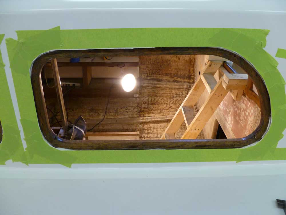
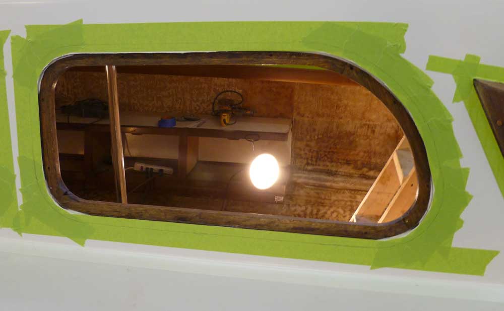
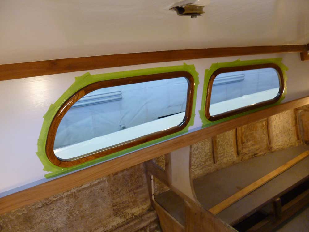
To begin the layout for the new wooden deadlight frames, I masked around the exterior openings to protect the paint and give me a place to make layout marks, etc. The new frames had to perform one main function: to secure the glass deadlights in place and provide a way to seal them against water. In addition, the frames needed to be generally attractive and in keeping with the boat's appearance.
The interior mahogany frames were constructed in such a way as to provide the recessed area against which the glass would rest and seal. The recessed area was essentially the same depth as the glass was thick, so the new trim could have a flat back side, making milling and installation easier.
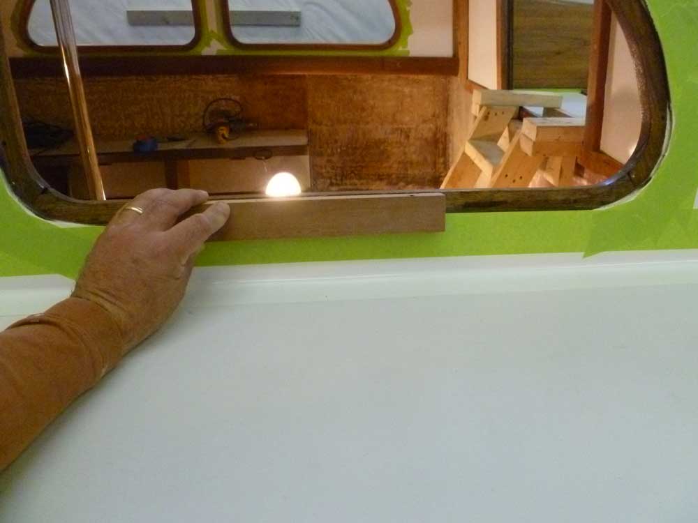
I thought the new frames needed to mirror and completely cover the interior trim where the glass would rest, which was about 3/4" wide. This trim was also fair and consistently-shaped, which meant that using it as the basis for the exterior trim would by translation make that trim also shaped as the openings were intended.
To provide a means of overlapping the seam, as well as room for screws to secure the trim, I thought that the trim would need to be a minimum of 1-1/2" in total width, so that's the dimension I began with. From a 3/4" thick piece of scrap mahogany, I milled a test sample to the appropriate width, which seemed to be a reasonable size: it covered completely the overlap of the inside trim (which would look the best), and still gave me room to drive and bung screws through the trim outboard of the opening and into the sides of the cabin trunk.
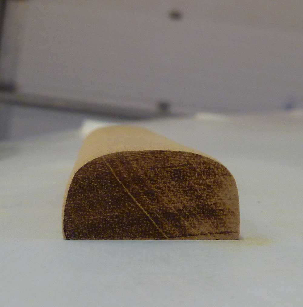
Next, I milled a profile on the sample that I thought would look good. I rounded the outer edge with a 1/2" bit, and the inner edge with a 1/4" bit. Upon reflection, however, the 1/4" radius seemed too abrupt and didn't look quite right, so I milled a matching 1/2" roundover on what would be the inside edge of the trim, which looked better. Even so, I wondered about increasing the radius on the inside edge to give the trim an asymmetrical profile that swept naturally down to the glass, but for the moment left things alone.
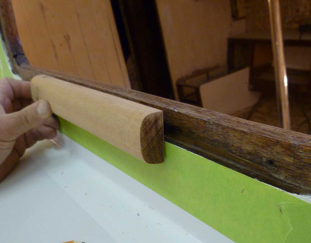
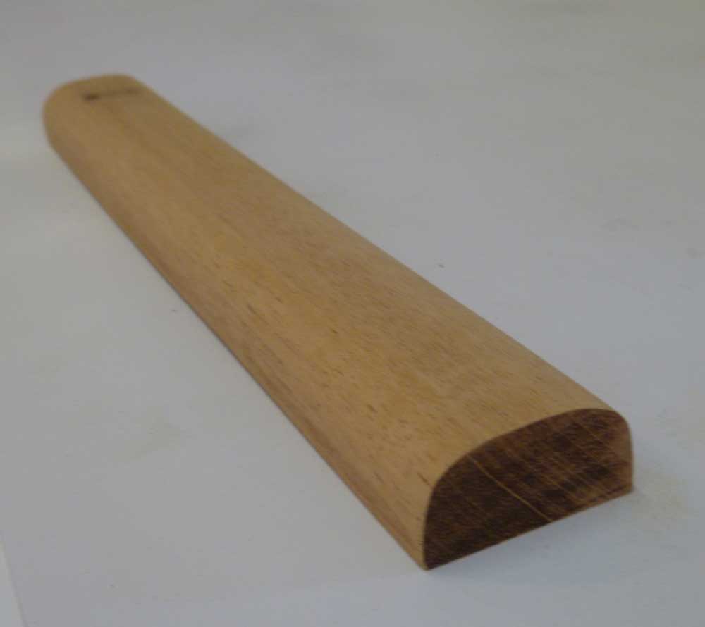
The width is 1-1/2", and the thickness 3/4".
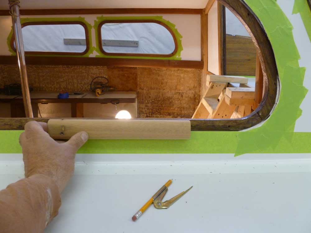
With a piece of the glass set in place, I tried out the trim again to see that things were fitting the way I anticipated.

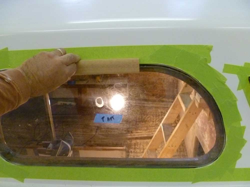
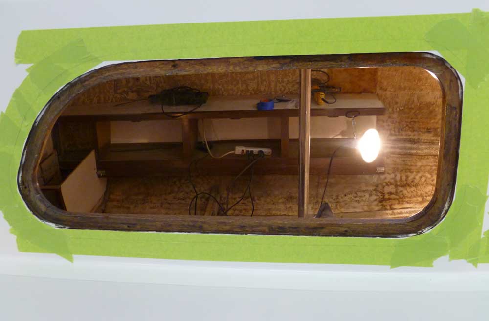
Afterwards, I marked out a general outline on the tape surrounding the opening, to simulate the overall size and shape of the new trim. The pencil lines seen on the tape in these photos represent the outer edge of the proposed trim, and follow exactly the size and shape of the inner edge of the opening, with enough room for screws to secure the trim (and therefore the glass) in place.
For the moment, I'd proceeded as far as I could with this process, and I sent off photos and information to the owner for his input, comments, and approval.
Next, I turned my attention to the engine installation. With the basic template in hand and complete, it was time to start laying things out in the boat so that I could build the new foundations, which I expected to begin soon once the new materials arrived.
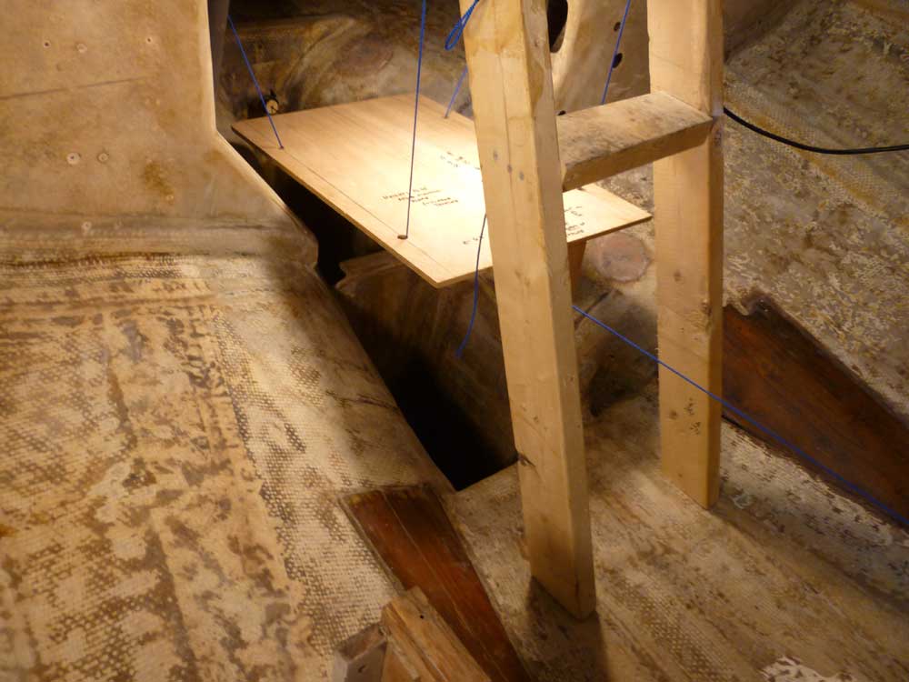
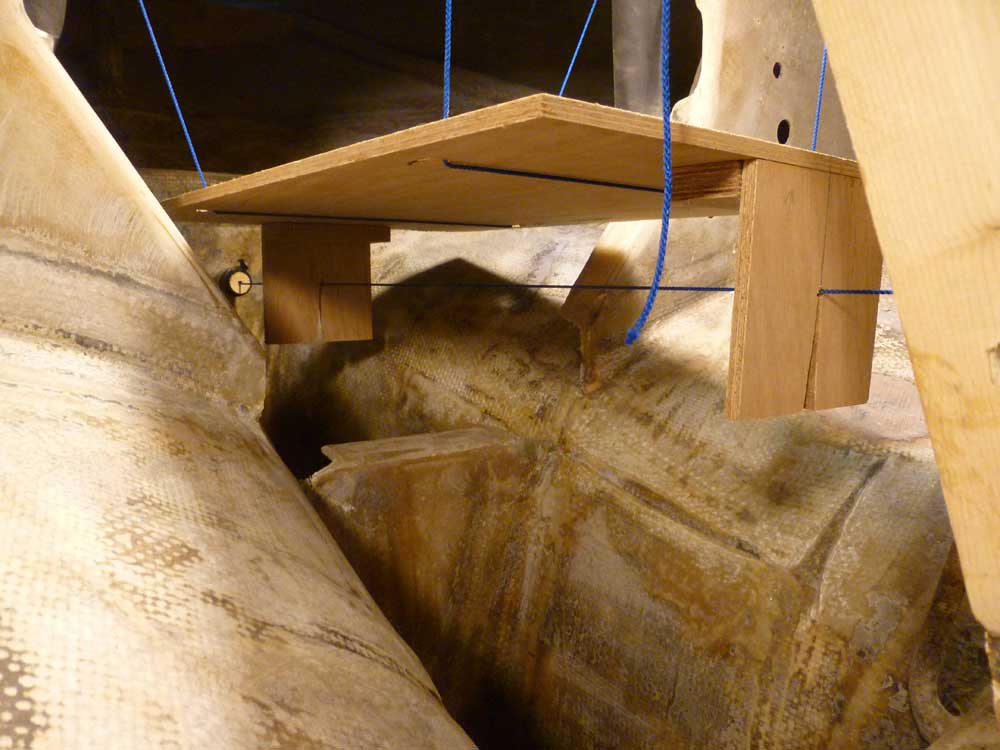
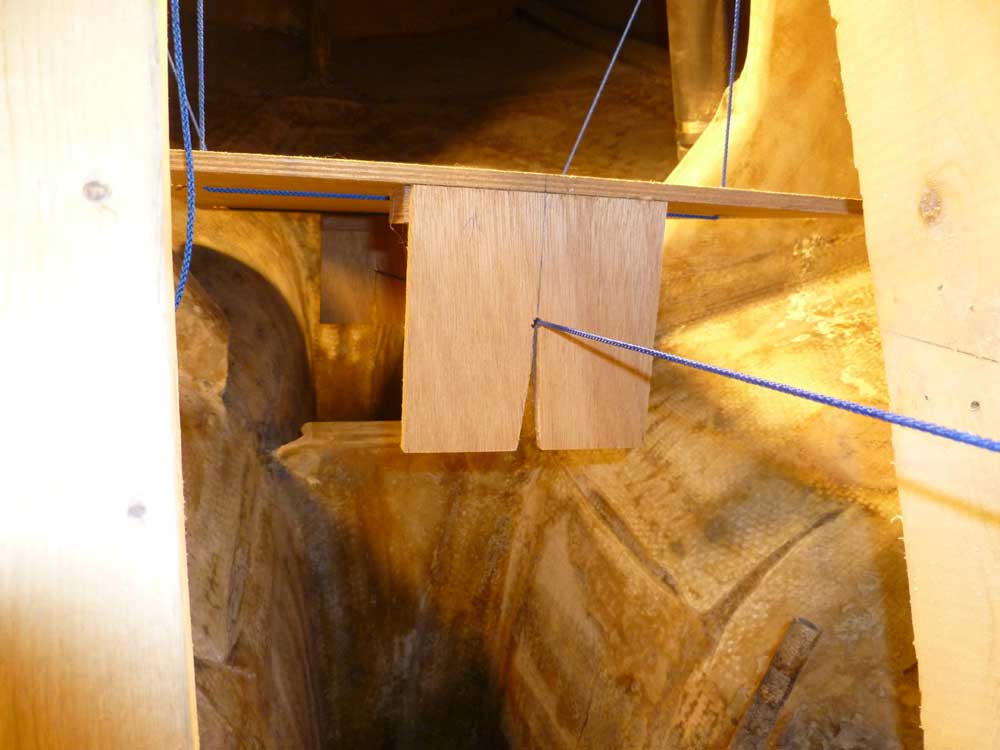
First, I ran a string through the center of the stern tube, holding it in the center of the tube at each end with little wooden plugs (with the string running through holes in the centers of the plugs). Inside the boat, I eventually secured the string to the aft end of the centerboard housing, which ended up being the most convenient place to locate the string. I adjusted things till the string passed through the center of the hole on the inside of the stern tube and tied it off tightly.


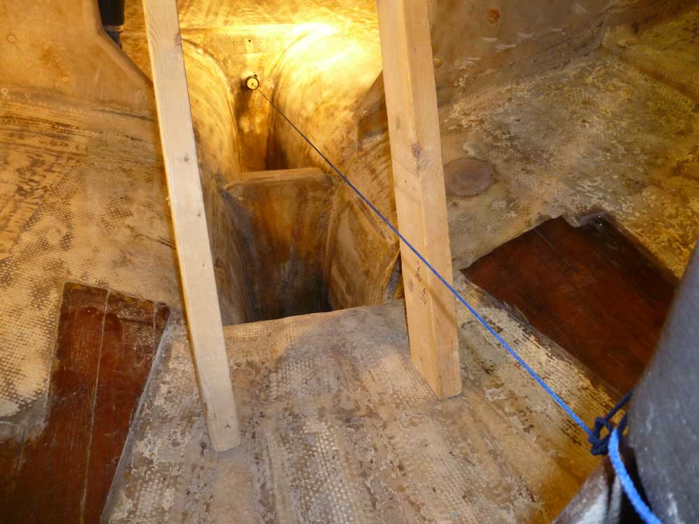
To get an idea how the engine would fit in the compartment, I slung the template from above with some string, a rather awkward and imprecise arrangement that I vowed to change later, but for the moment, at least, it allowed me to position the template more or less where it (and therefore the engine) would eventually end up and assess how things fit in a general sense. The string represented the center of the prop shaft, which was the driving force for the engine's placement and angle.
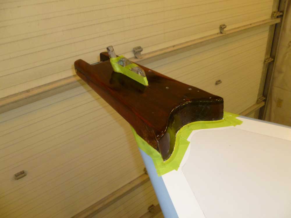
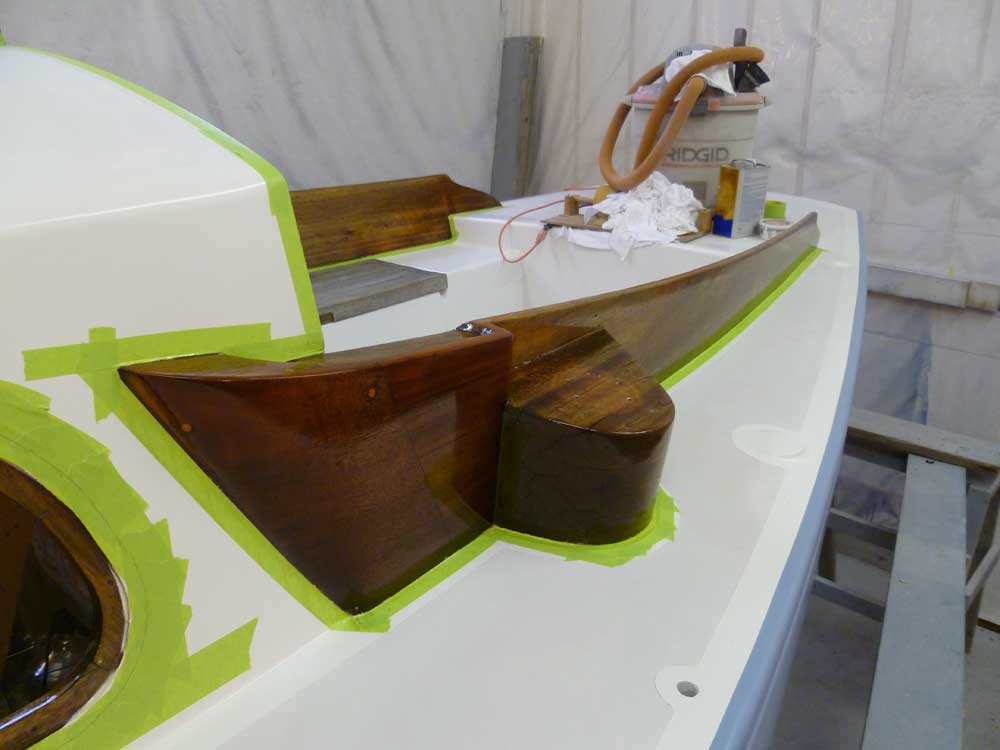
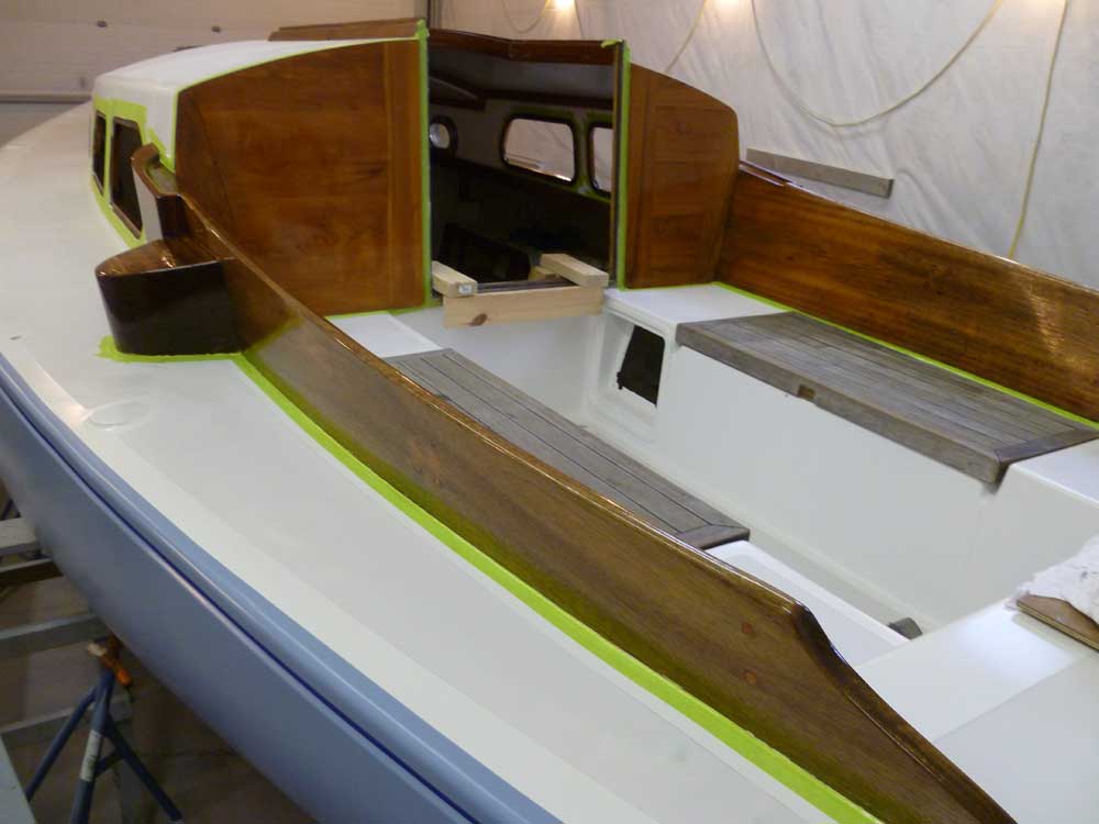
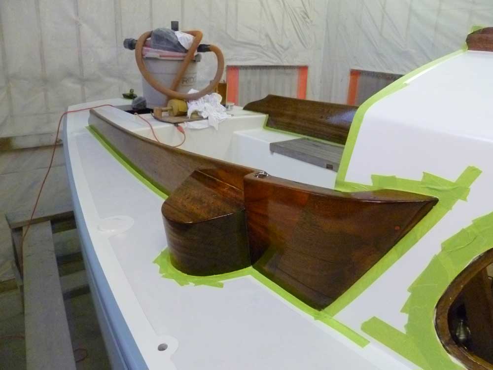
To round out the day, I sanded and revarnished the deadlight trim, cockpit coamings, and anchor platform.


Total Time Billed on This Job Today: 6 hours
