
110 Cookson Lane | Whitefield, ME 04353 | 207-232-7600 | tim@lackeysailing.com
Snow Lily | Friday, March 22, 2013
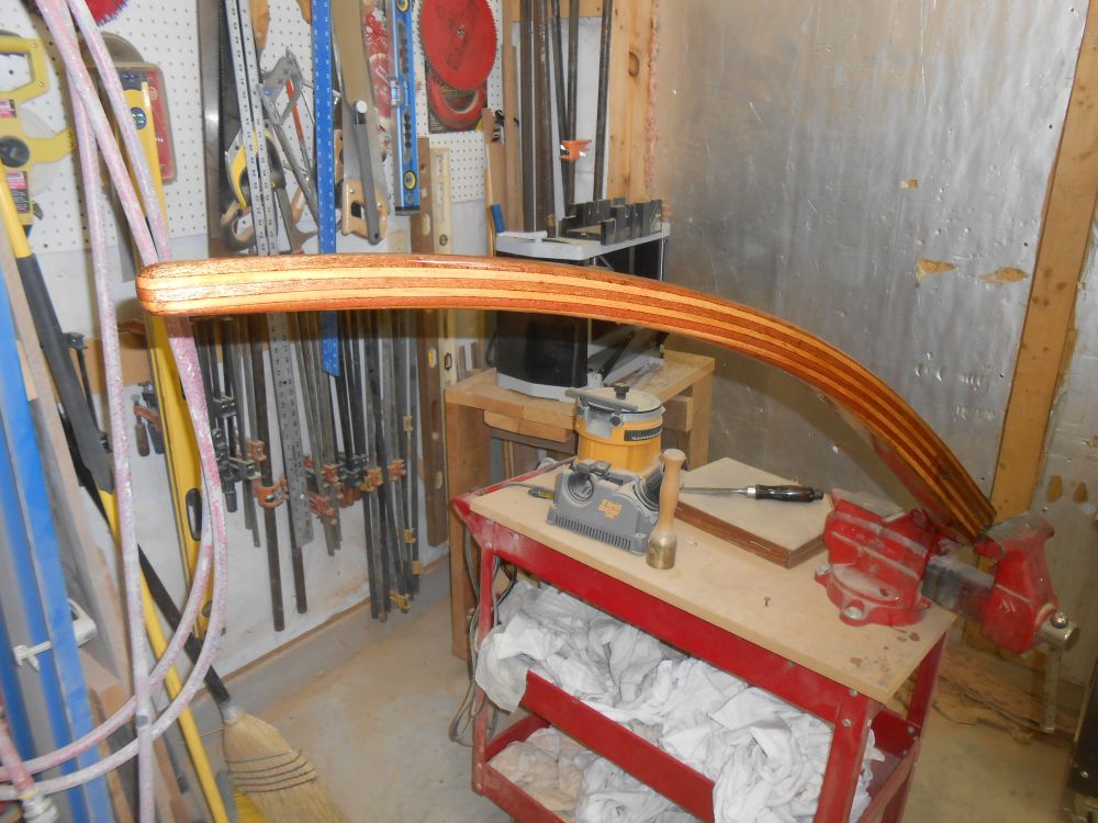
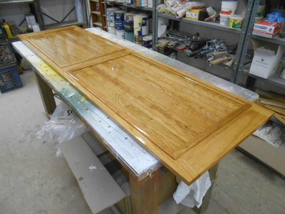
Before getting into the wiring for the day, I prepped and varnished once more the tiller and head door to keep that process moving along.
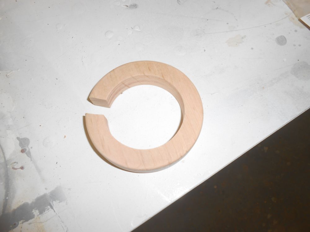
From 3/4" cherry, I prepared a little backing ring for the nav station light to provide room for its wiring--and that of the settee light on the opposite side of the bulkhead--to exit. After sanding it smooth, I started the varnish buildup before installation.
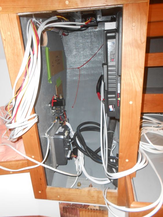
The next step in the ongoing electrical installation was to concentrate on the propulsion motor side of things. The system that the owner selected and purchased with an outside vendor contained a number of components that I planned to install in the electrical locker and nearby as needed, including a solar charger/controller; 48-volt distribution box; 48V - 12V DC converter; 48V - 24C DC converter; electric motor controller and related items. Also specified by the vendor and owner as part of this specific system, and to be installed here but not yet on hand, was an AC inverter and a shore power charger, plus a battery management system. A lot of components and complexity to fit into an increasingly small space, but fortunately this locker space was almost tailor made for the task, though it was quickly becoming less roomy than it once seemed.
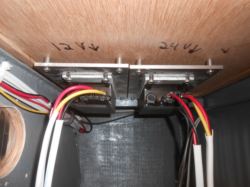
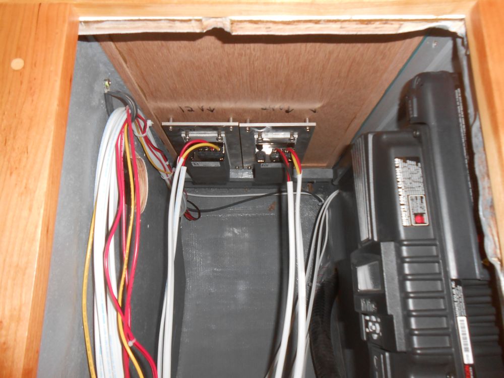
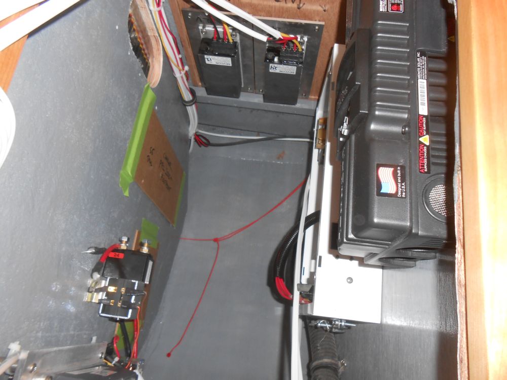
To preserve critical wall space inside the locker, I began by installing the two DC/DC converters on the overhead of the locker, keeping them out of the way but convenient for wiring. These converters came from the vendor with attached aluminum heat sinks, large plates to help draw away heat from the converter, and to aid in airflow and heat transfer I mounted the units on spacers away from the overhead. For now, I secured the attached wires to one side to keep them out of the way during the remaining work.
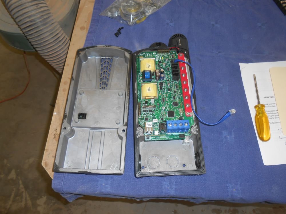
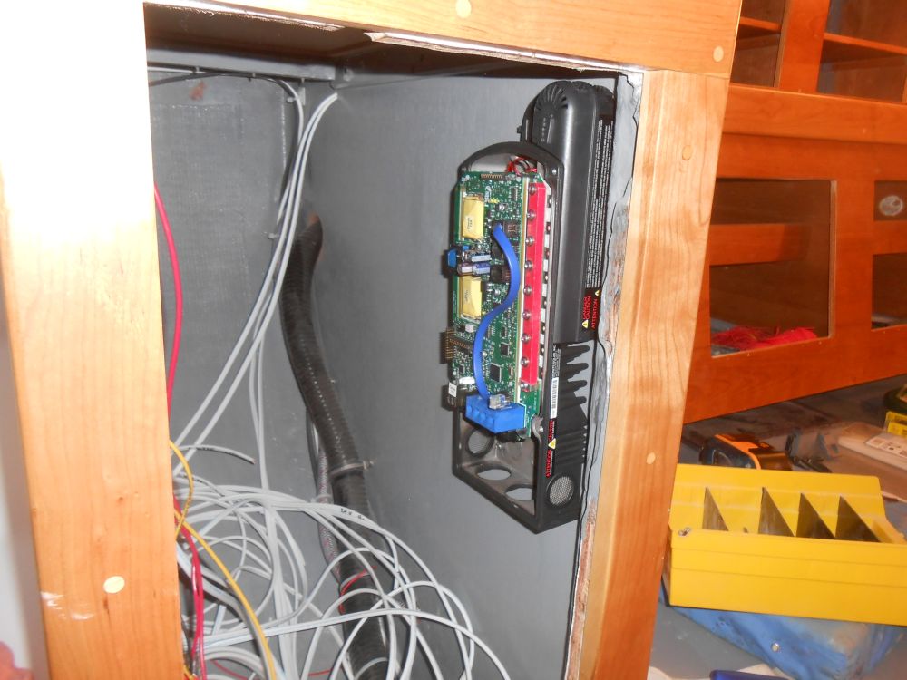
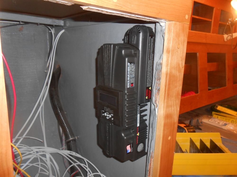
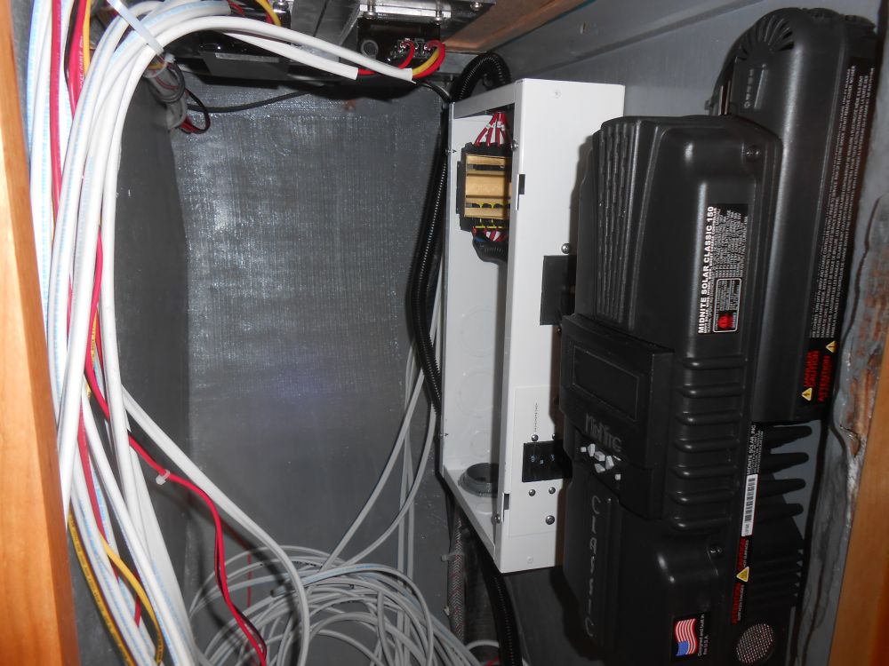
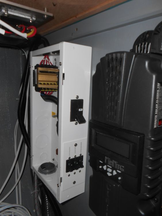
The solar controller was a complicated, unit that seemed to be designed for significant off-grid power distribution, with many programmable features that would require access to its front panel and LCD screen, so I chose to mount it just inside the door to the locker, on the forward side, where access would be good for those who needed to program the system later. To install it, I removed the front panel, but later reinstalled the panel for protection till I'd need to remove it again to install the wires required.
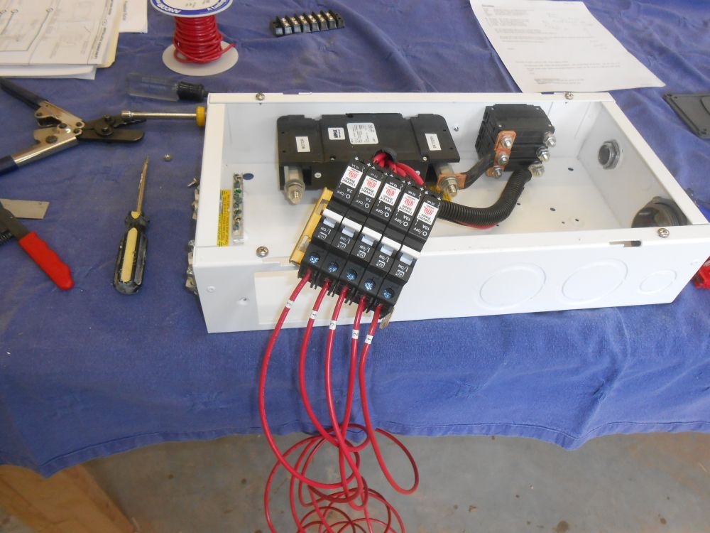
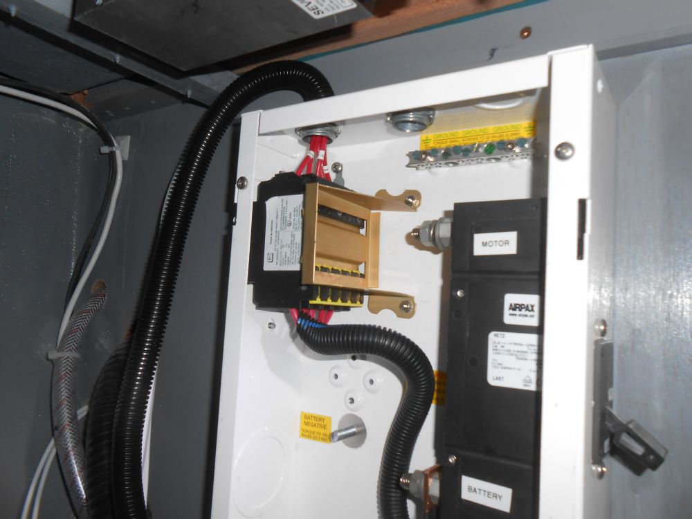
The 48-volt distribution box supplied by the propulsion vendor contained a main propulsion system breaker (250A), with various smaller breakers to service some of the other items in the system. A set of five breakers at the top left corner of the box would be impossible to wire with the box in its required position within the locker, so before installing it I prepared a wiring harness and terminal block to allow remote connection of these five circuits later. I left enough length to give me freedom in determining the best mounting location inside the locker later.
These circuits serviced the two DC/DC converters; a battery monitor; the solar controller; and the logic control for the motor control (I wasn't sure what that was, as it wasn't shown on the wiring diagram from the vendor, but would find out in due course.)
The design of the box and location of these circuit breakers made it hard to install the wires at all--I was glad I'd determined earlier that I'd need to do something on the bench first--and in fact I found it more convenient to remove the bracket securing the breakers and pull them out for ease of wiring, given the tight access to the wire clamps at the top ends of the breakers. With these removed, the job was straightforward, and after reassembling the box I secured it to the forward bulkhead in the locker, just outboard of the solar controller. I could access other areas of the box for wiring after installation, though I'd pre-installed wire clamps within several of the box's knockouts.
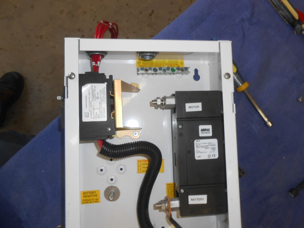
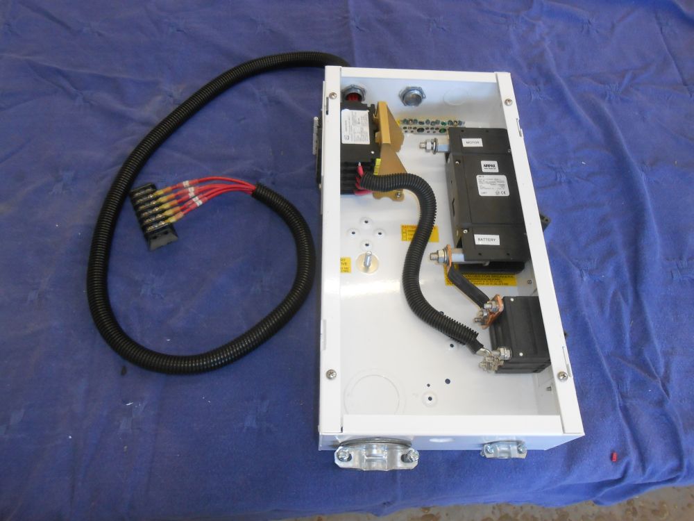
The next thing to install was the motor controller, the main electronic brain for the whole system. Before I could determine the best position for that, I had to determine the length of portions of the pre-wired harness, which incorporated the wires to the throttle, contactor, a relay to run an engine room fan (which lead was going to be far too short to reach the engine room regardless), two leads for sensors to the electric motor itself, and the main multi-pin connector to the controller itself. These wire lengths varied and were finite, but specifically I needed to ensure that wherever I placed the controller, there'd be adequate wire length for the two sensors to the engine room. So I separated out and tried to make sense of the various legs of the harness as a starting point.
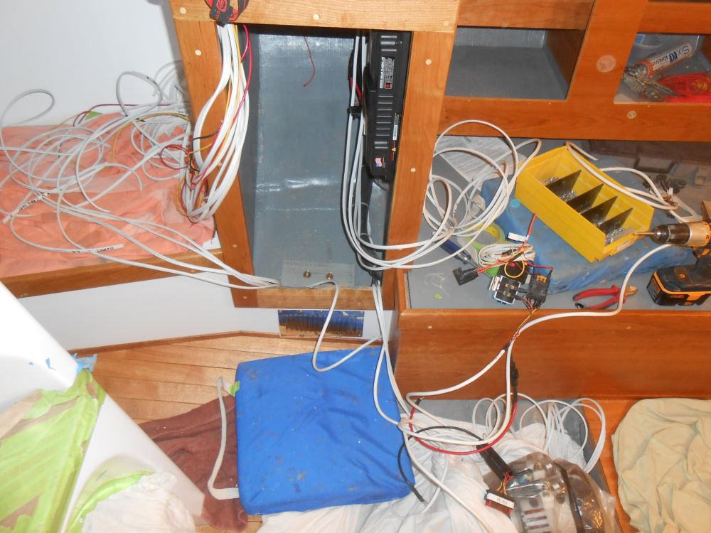
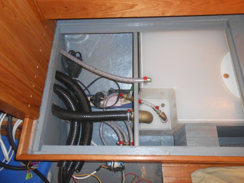
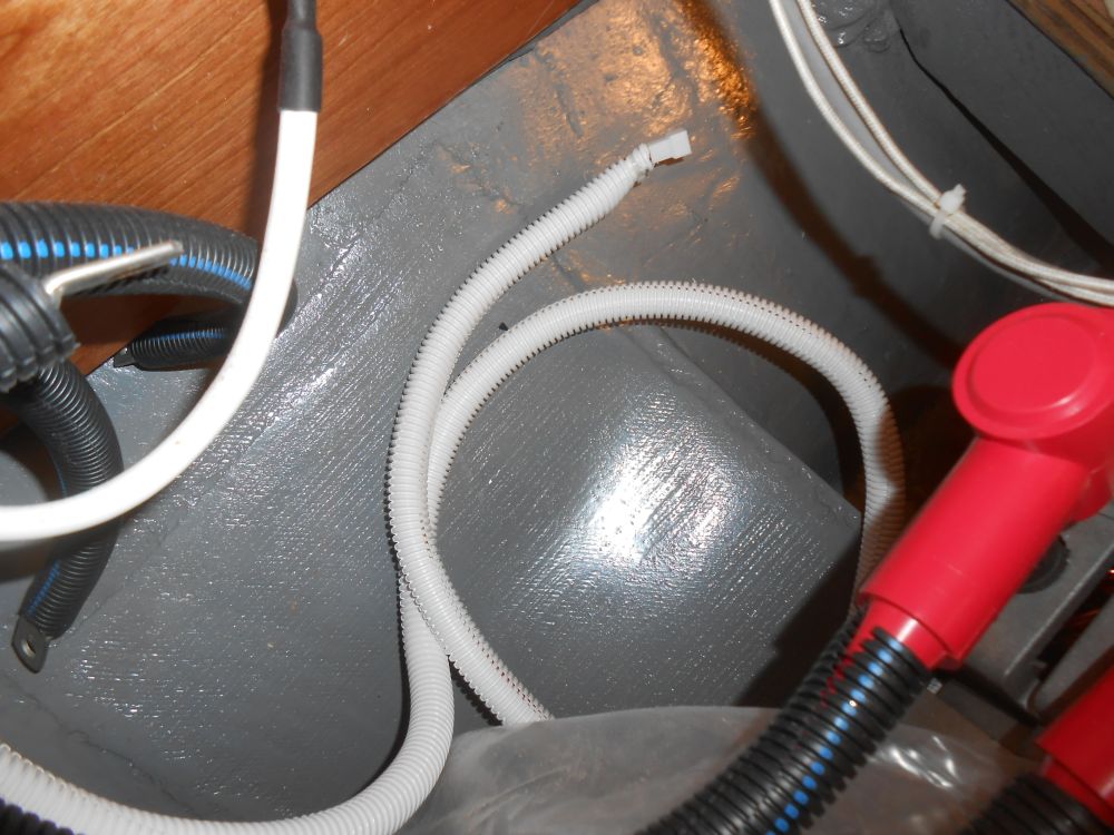
This led me to create the wire runs from the locker to the nearby engine room. In addition to the sensor wires and the fan wiring, there'd be three #2 AWG cables to connect the motor itself to the controller; these cables were supplied by the vendor as part of the system. The sensor wires needed to be separate from these larger cables, so I created three wire chases from 1-1/2" flexible conduit (i.e. hose), two containing the large cables and the third for the other wiring, including a wire pair for the fan. I led these conduits through the aft part of the port settee locker, a short and convenient run.
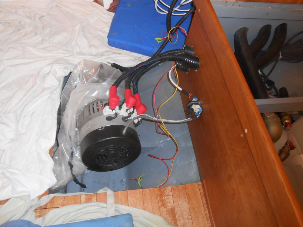

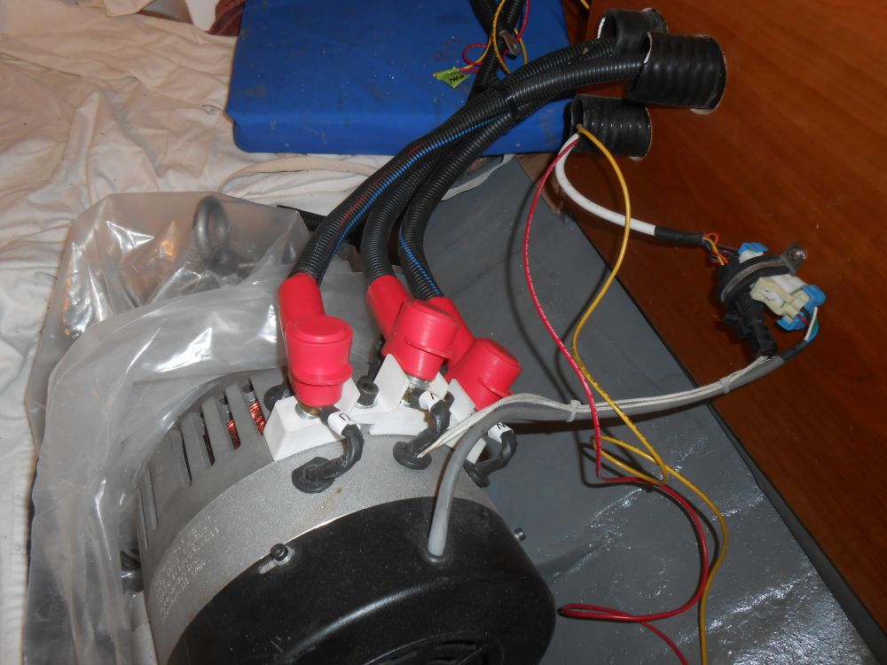
Connecting the electric motor was a breeze. The three cables, which I'd labeled at each end for my own reference and convenience in later connections to the controller itself, connected to three terminals atop the electric motor, which I then covered with supplied boots. The two sensor wires included quick-snap connectors, and I secured these wires to the nearby bulkhead once I'd made the connections. After cutting a little plug off the end of the fan wiring at the wire harness inside the locker, I reconnected it to the new wires inside the engine compartment, leaving ample slack to allow for the fan to be positioned wherever (since I'd not yet built the engine room box in which the fan would be installed), and protected the wires with split loom. (the first picture in this series actually jumps ahead a bit)
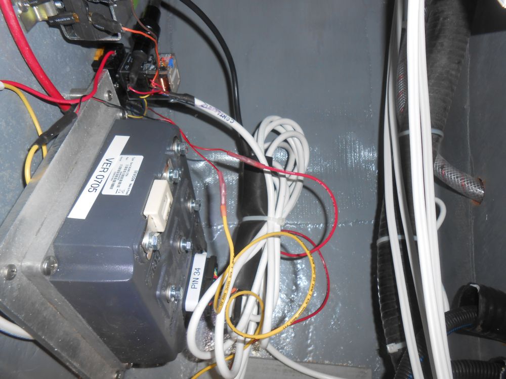
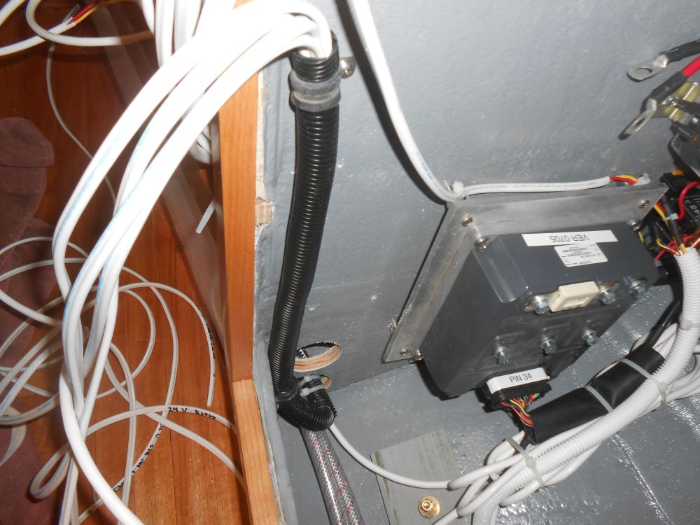
With all this done, I could select the location for the controller and install it. The best location turned out to be near the bottom of the after side of the locker, and a bit towards the hull. I installed the controller, which would generate heat and also came with its own heat sink plate, with screws and 1" spacers.
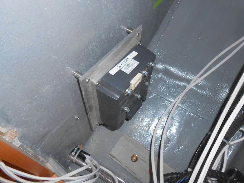
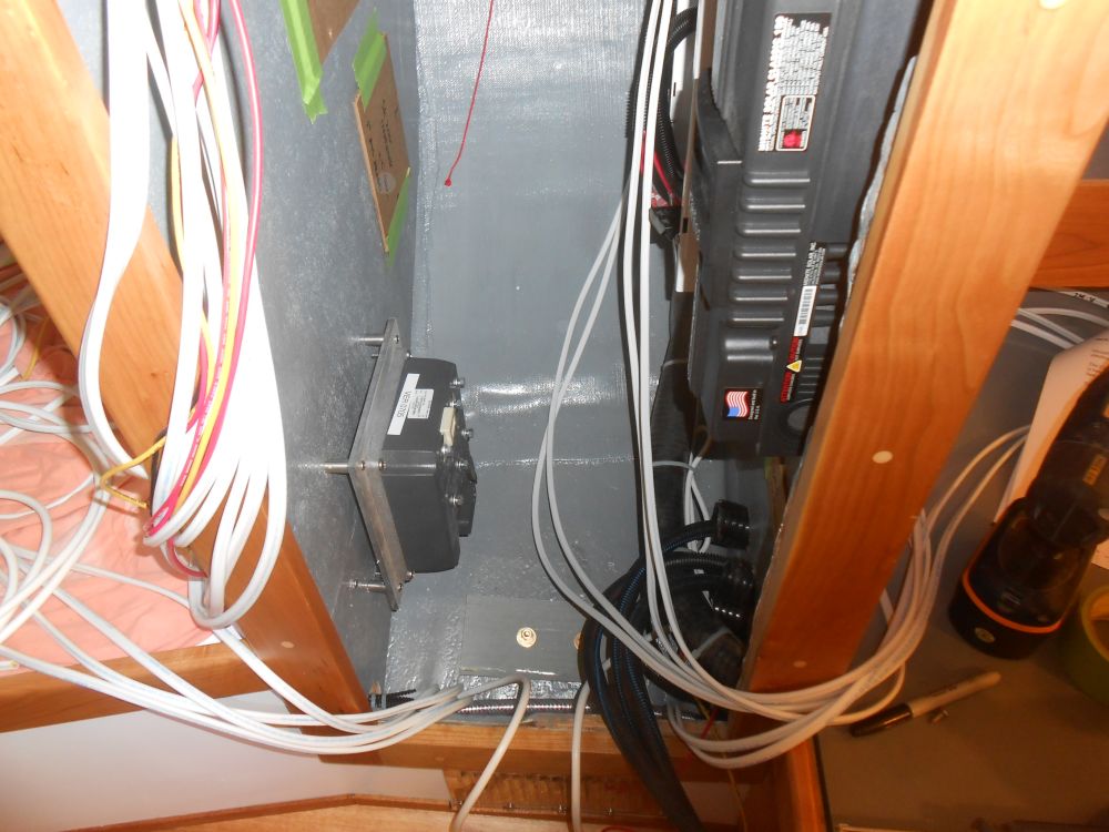
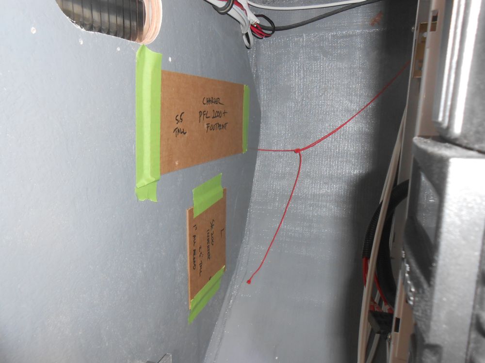
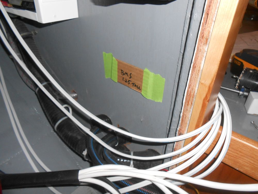
This left ample room on the aft bulkhead for other wiring connections, including various terminal blocks and distribution busses I'd need to install as I wired the panels, and also left plenty of room for the shore power charger and inverter, scale cardboard cutouts of which I made and taped to the bulkhead to ensure plenty of space. The little BMS module would fit almost anywhere, but for now I placed it's avatar beneath the solar controller. There'd be ample room for it elsewhere too, but at the moment I wasn't sure how this tied into the whole system.
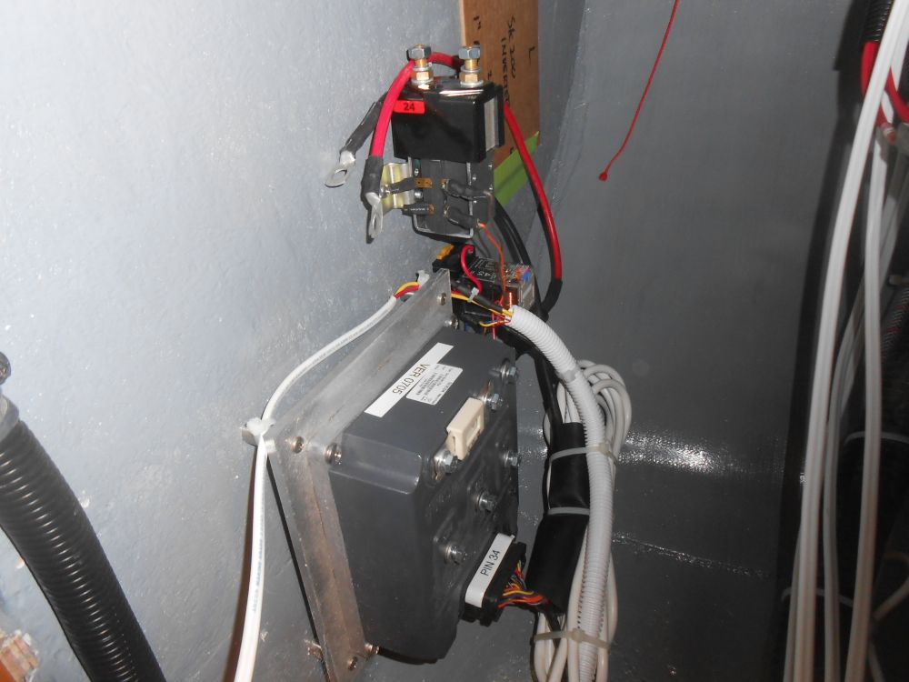
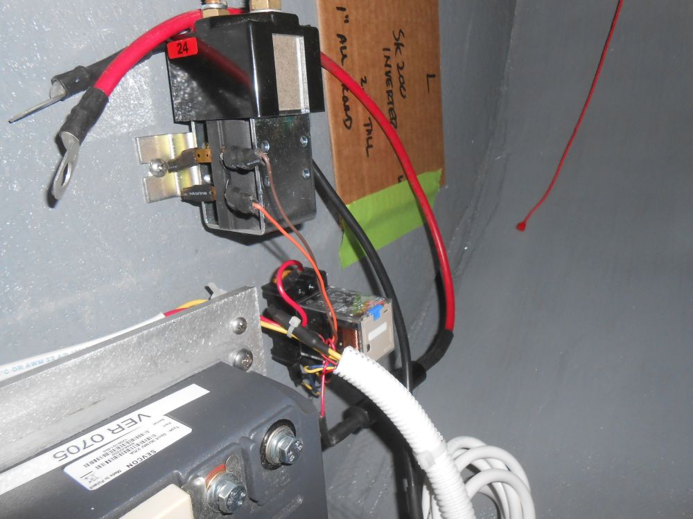
Attached with fairly short lengths of wires out of the massive interconnected wiring harness was a contactor and a relay, and after a couple iterations I ended up locating these just outboard and above the motor controller, where access was good but they were out of the way; the relay in particular looked terribly delicate. The contactor would eventually be wired inline with the main battery cables, according to the wiring schematic, and there was ample room and access for this.
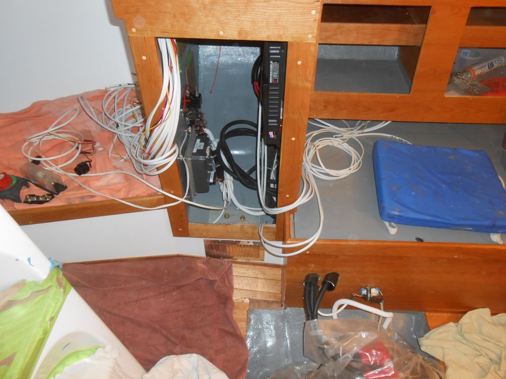
With those main components installed, I sorted and bundled what wires I could, preparing me for continuing work next time.
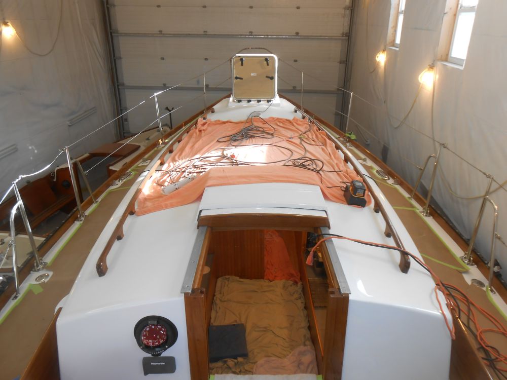
Also, earlier in the day my rigging vendor arrived to install the new lifelines. The port gate is slack here because I had the aft lifelines disconnected to ease access to and from the boat.
Total Time on This Job Today: 8.5 hours
