110 Cookson Lane | Whitefield, ME 04353 | 207-232-7600 | tim@lackeysailing.com
Snow Lily | Thursday, February 14, 2013
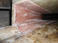
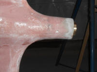
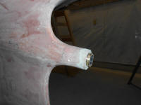
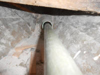
I began, once more, with the engine foundations and keel extension, washing and sanding the new fiberglass (inside) and small faired areas (outside). With the work outside the boat complete, I installed the Cutless bearing in the tube, securing it with a pair of set screws. I always leave 1/4" or so of the bearing exposed outside the stern tube to make future replacement easier by providing a place to grab the bearing.
Next, I test-fit the simulated shaft and electric motor on the new platform to determine whether I needed to add more fiberglass and raise the platform height accordingly. With the shaft in place within the coupling, I bolted the shaft coupling to the transmission coupling and aligned the assembly as needed to keep the shaft centered in the stern tube. I found that the height was essentially perfect, so I'd not need to add more fiberglass to change the platform height.
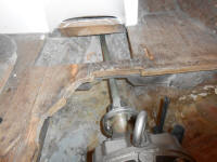
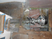
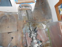
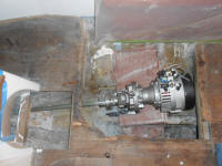
With the assembly aligned as closely as possible, I made some reference marks on the platform, then used the simulated shaft to measure and calculate the required length of the propeller shaft, taking into account the prop hub, thread length, and other factors as needed, so I could order the new shaft. I'd wait to permanently locate the electric motor till I had the actual shaft and coupling on hand.
A view to the transmission coupling from the outside of the stern tube
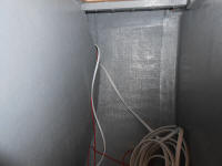
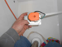
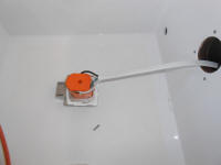
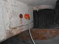
While access was at its best before the traveler started getting in the way, I installed the shore power receptacle in the cockpit, which would be required to keep the battery bank charged up between uses. To make installation easier, I ran a 3-conductor cable now, so I could wire the receptacle before installation. I ran the cable from the electrical locker to the aft part of the boat, outside of the quarterberth through an open space inside the molded unit. At the same time, planning ahead, I ran another 2-conductor cable for the stern light, as well as a messenger line to make running additional wiring, if needed, easier.
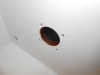
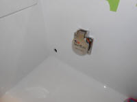
After drilling a 2-1/2" hole in the desired position, I dry fit the receptacle and drilled and tapped for four #8 fasteners. Then, since there was a plywood backing glassed to the side of the cockpit in this area, I treated the exposed wood with epoxy before continuing.
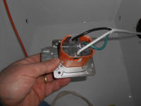
The new 30 amp inlet fitting featured a new design that I liked, with a new prong design and shape that precluded the annoying twist-lock connections on traditional shore power receptacles, but this was my first time using this particular fitting. The only way to wire it was to strip the wire ends bare and insert them from the back of the fitting into special wire clamps within, tightening the screws securely. I would have preferred to side wire using ring terminals, but the design of the fitting precluded that.
In any event, with the wiring connected and the back cover plate installed, I applied sealant to the flange and installed the fitting with four screws. I'd come back and tie up the wiring later, once I started to concentrate on other wiring tasks.
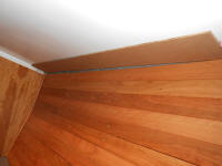
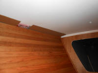
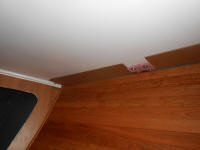
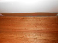
In the forward cabin, I made cardboard templates of the flat trim pieces required to span between the molded fiberglass liner and the edge of the deck, an ugly, uneven seam. With a stanchion backing plate taking up some of the middle of the overall length, I decided on four separate pieces of trim to cover the seam.
Scribing the cardboard to match the shape of the hull and opening at hand, I transferred the measurements to 9mm plywood and cut out the final pieces. I test-fit each piece and made adjustments as needed; no photos of this since I couldn't hold the piece in place and take a picture at the same time, and I'd wait to introduce screws till the final installation.
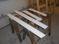
With all four pieces cut, edge-milled, and sanded, I applied a coat of primer to begin the finishing process.
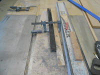
I'd hoped to get back to the genoa tracks, but by the time my new bolts arrived it was later than planned, so instead I focused on the traveler and the required wedges beneath. From a 1-1/4" wide by 1-1/2" tall blank of black UHMW polyethylene, I cut a pair of wedges to the required dimensions, tapering from 3/4" tall at the outboard end to abotu 1/8" at the inbord end, over the 14" length of the piece. To cut the wedges, I threw together a quick jig for the table saw, which allowed me to cut both pieces from one end of my blank.
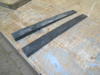
After testing the fit beneath the traveler, I marked each wedge for four fasteners over its length. The traveler featured variable bolt spacing, so I was free to lay out the bolts in the best position for this installation. With the holes drilled through the spacers, I marked their position on the deck, and drilled 5/8" holes through the top skin and core to remove the core, before cleaning up and filling the voids with a thickened epoxy mixture.
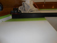
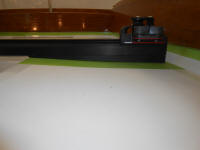
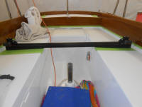
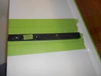
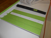
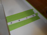
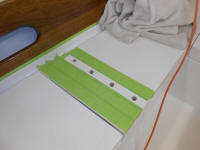
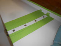
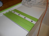
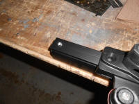
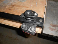
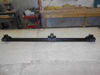
Finally, I installed the main traveler car on the track, which had to be done before final installation, then permanently installed the two end units by drilling and tapping the ends of the track for a 5/16" machine screw to pin the ends in place.
Total Time on This Job Today: 8 hours
