
110 Cookson Lane | Whitefield, ME 04353 | 207-232-7600 | tim@lackeysailing.com
Snow Lily | Tuesday, February 5, 2013
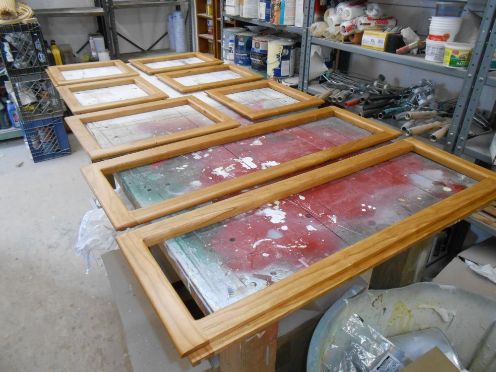
After lightly sanding the cabinet doors, I applied another coat of varnish--this time rubbed-effect satin varnish to match the remaining interior. I also sanded the coamings and handrails, but didn't have time to get back to their varnish on this day.
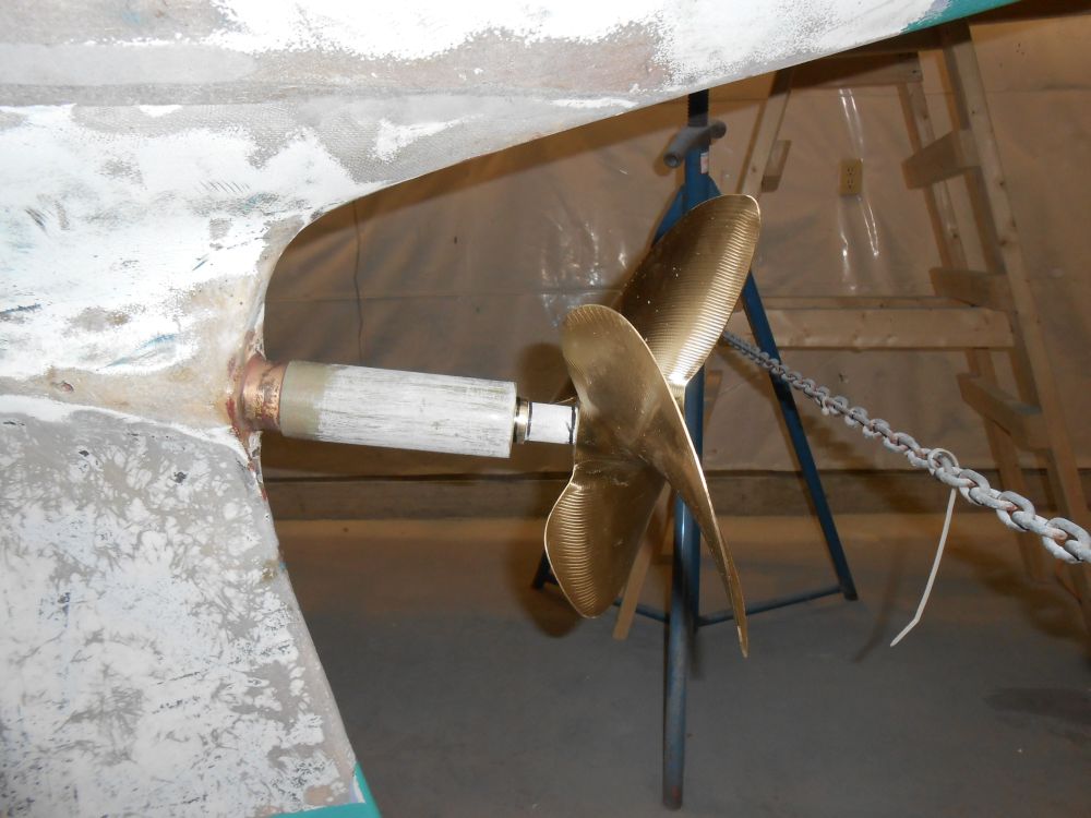
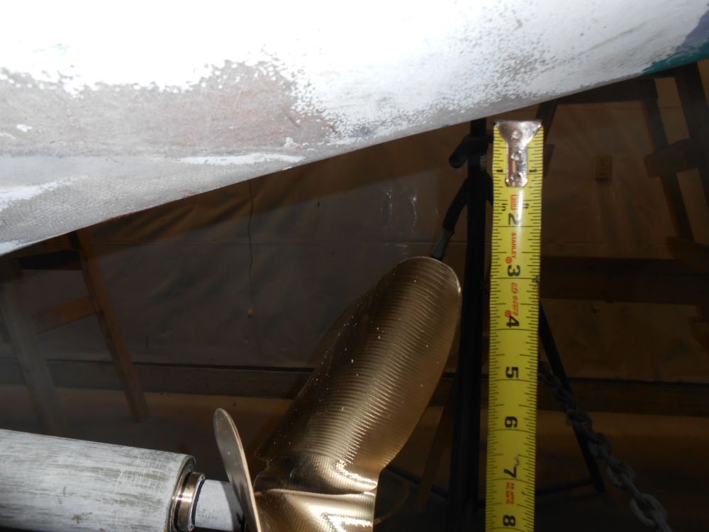
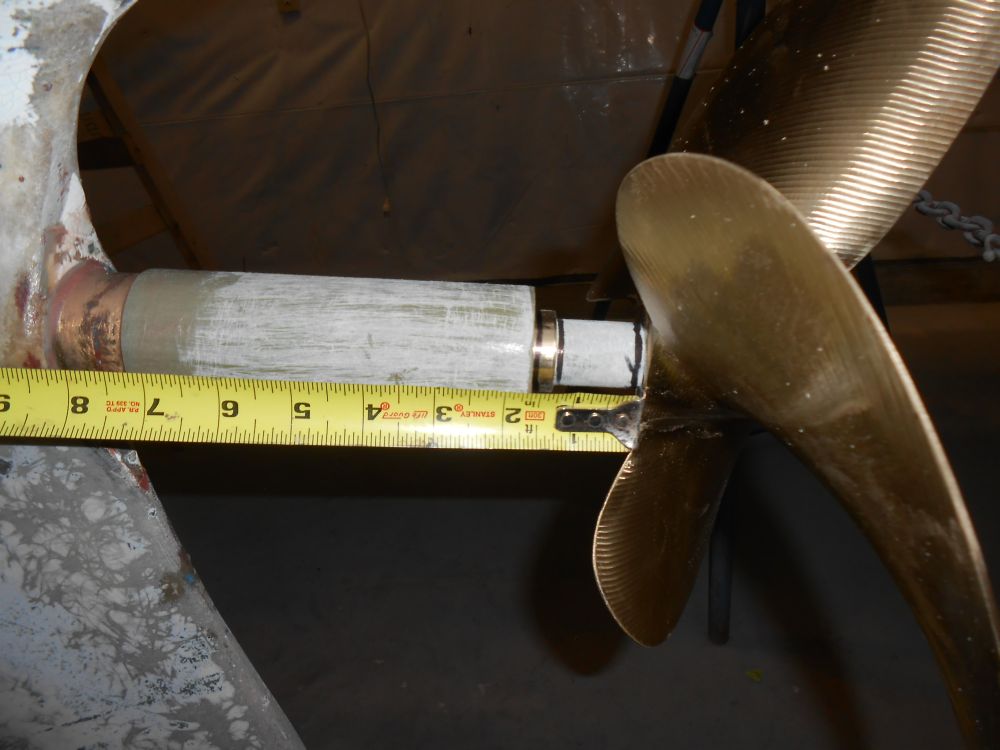
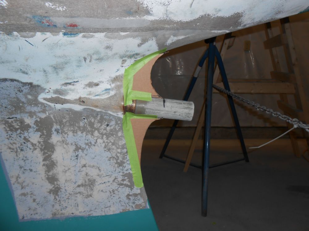
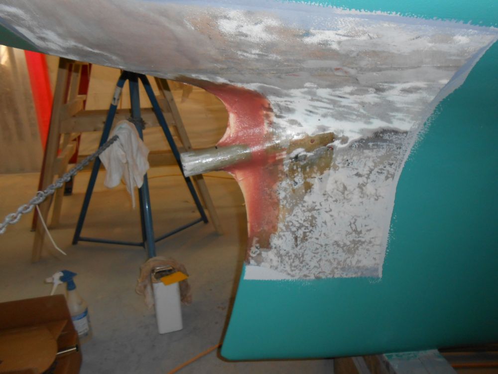
Now that the fiberglass stern tube extensions were securely glued in place, I triple-checked the propeller location and clearance with the false shaft in place. There was plenty of room, allowing for a little exposed shaft between the bearing and prop hub.
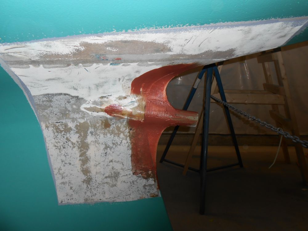
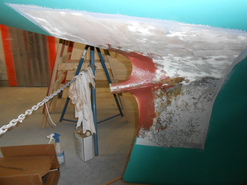
I continued the reinforcing process. To help support the longer tube, I created cardboard templates of some small additions to the trailing edge of the keel, maintaining the shape of the keel as much as possible while sweeping outwards to support the new stern tube appropriately.
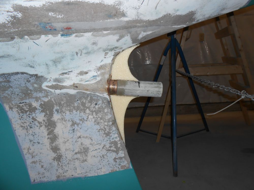
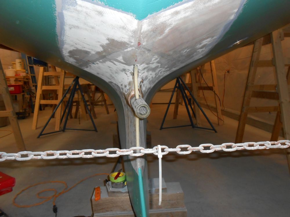
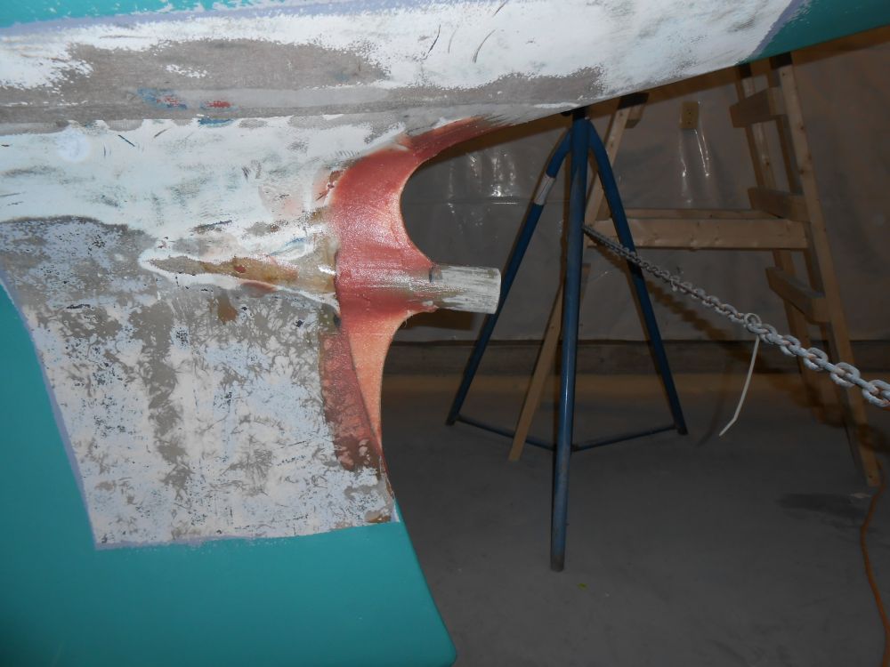
Satisfied with the basic shape, I transferred the cardboard templates to some Corecell structural foam, and glued the foam in place before using thickened epoxy to begin to secure in place and smooth in the new filers in with the keel and surrounding hull as required. I applied a first coat, then, later in the day while the first application was semi-cured but still green, a second coat to bring the new fairing close to its final shape. I'd continue this process with additional shaping, sanding, and fairing till the shape was where I wanted it before fiberglassing the whole area.
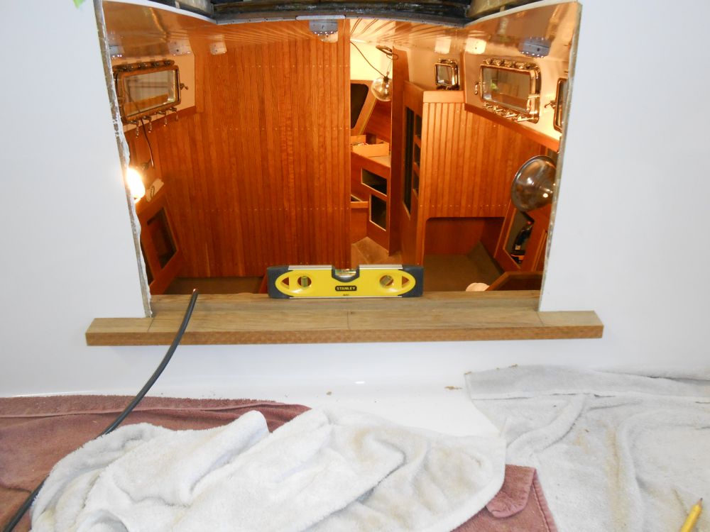
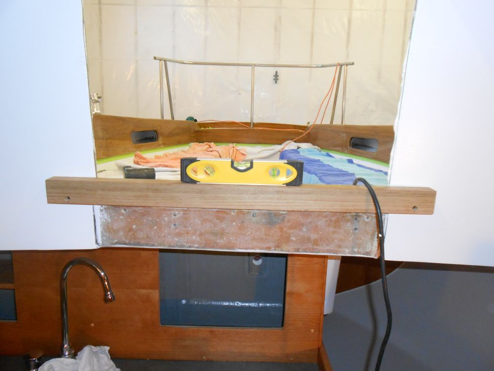
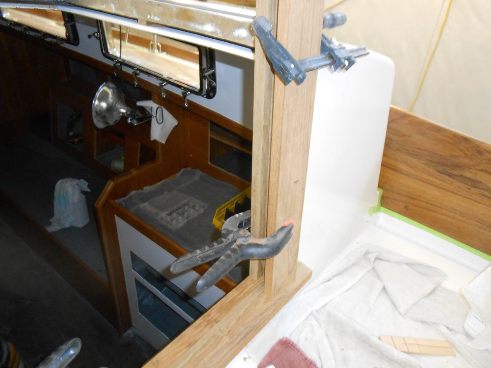
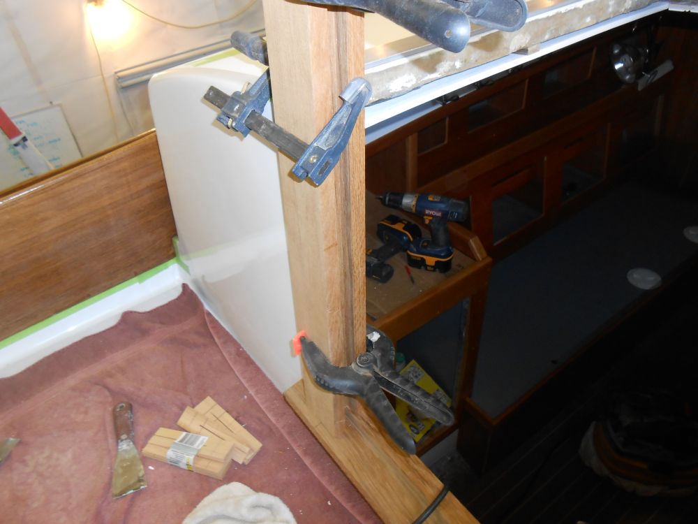
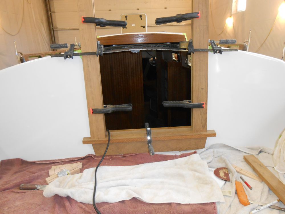
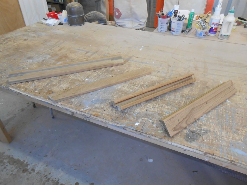
After digging out the old, splintered companionway trim from storage, I used it to roughly determine a plan for the new trim, beginning with the sill. With the old piece as a guide, but making some minor changes to suit my overall plans, I milled a new section from 8/4 teak. After a few test-fits to fine-tune the slots where the sill passed around the edges of the companionway opening, I leveled it and secured it in place for now with a couple screws.
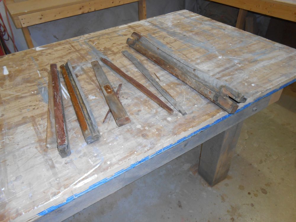
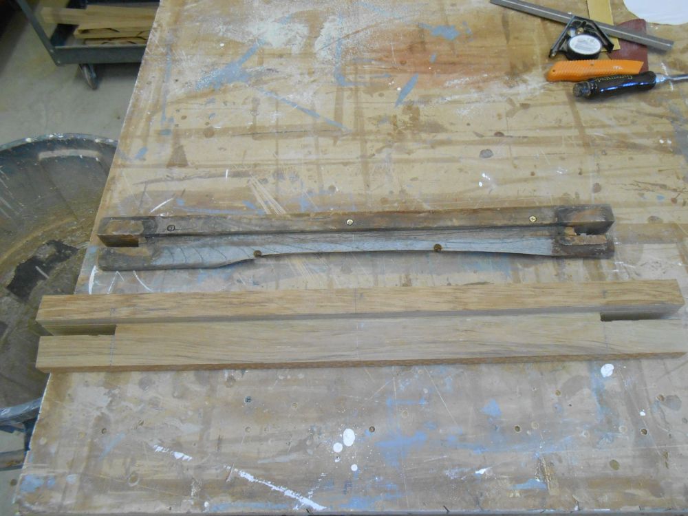
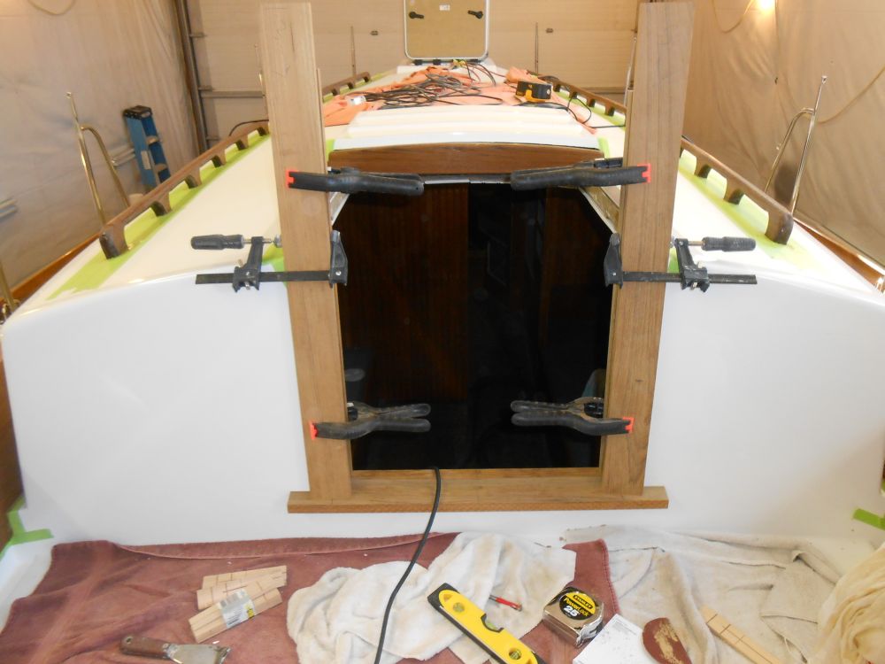
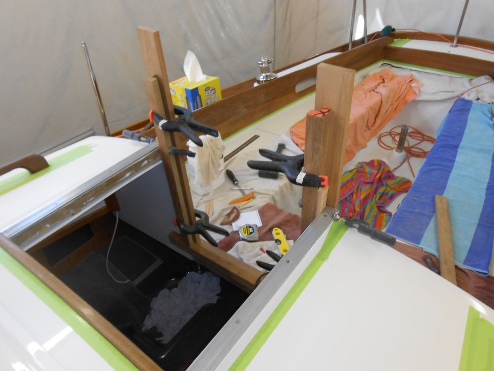
The vertical side trim had to incorporate slots for the swashboards, as well as wrap around the inside of the opening. There wasn't much to emulate from the original trim, and the old swashboards had been thin and flimsy, so I made some minor changes to the specifics of the trim to accommodate heavier swashboards and wider trim that I thought would look better. I built the side trim in two pieces: an L-shaped piece to form part of the slot for the boards, and wrap into the cabin; and a flat trim piece on the exterior, which completed the slot seamlessly. Leaving the rough pieces overlong for now, I cut the lower ends to fit the profile of the stool as required and clamped the various pieces in place, marking the top edge closer to its final height for trimming, though I planned to leave excess length till the final installation.
Finally, I cut a new apron beneath the sill. After the test-fit, and these photos, I made the piece a little narrower to provide just a bit more room between it and the bridgedeck.
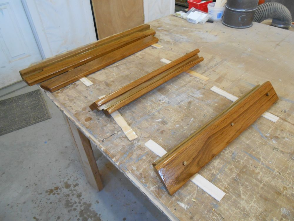
After drilling screw holes with the trim sections still clamped in place, registering their locations and placement, I removed the trim and milled edge details on all the pieces as required, then sanded them all smooth. After cleaning up, I secured the side trim pieces together with epoxy and screws, then applied a sealer coat of varnish to all sides of the new trim.
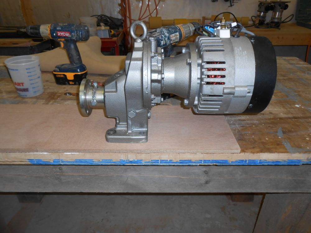
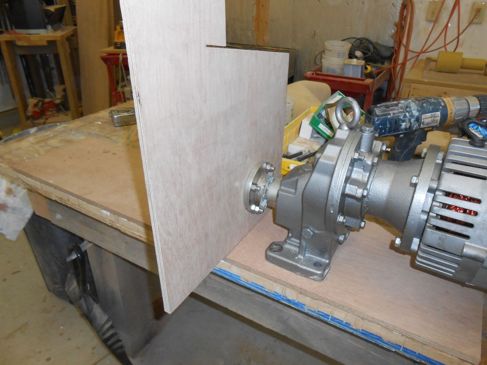
To make initial layout of the new electric motor foundation easier, I built a simple template of the motor base and, most importantly, the shaft location. The electric motor didn't require flexible or adjustable mounts, so the platform to which it'd be secured would be accurately located to the motor itself. The template would make the initial steps of this process easier.
Securing the motor to a length of scrap plywood and to the bench with temporary screws, I traced the coupling location on a vertical piece of plywood, and marked the position of the coupling face on the platform (i.e. the edge of the plywood I was holding against the coupling). I also marked the bolting locations for the electric motor.
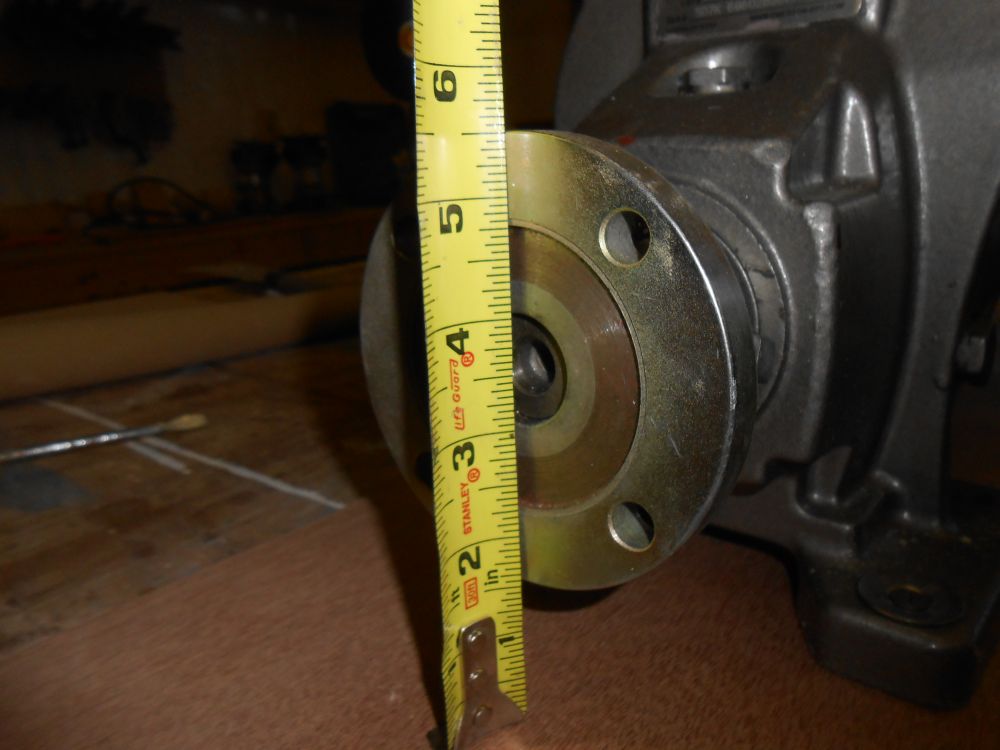
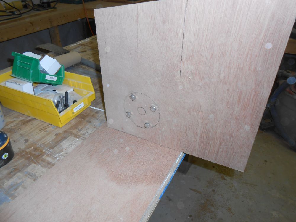
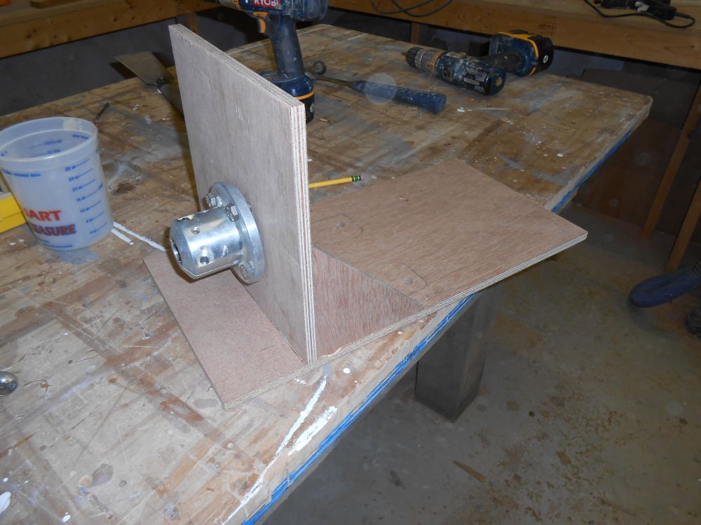
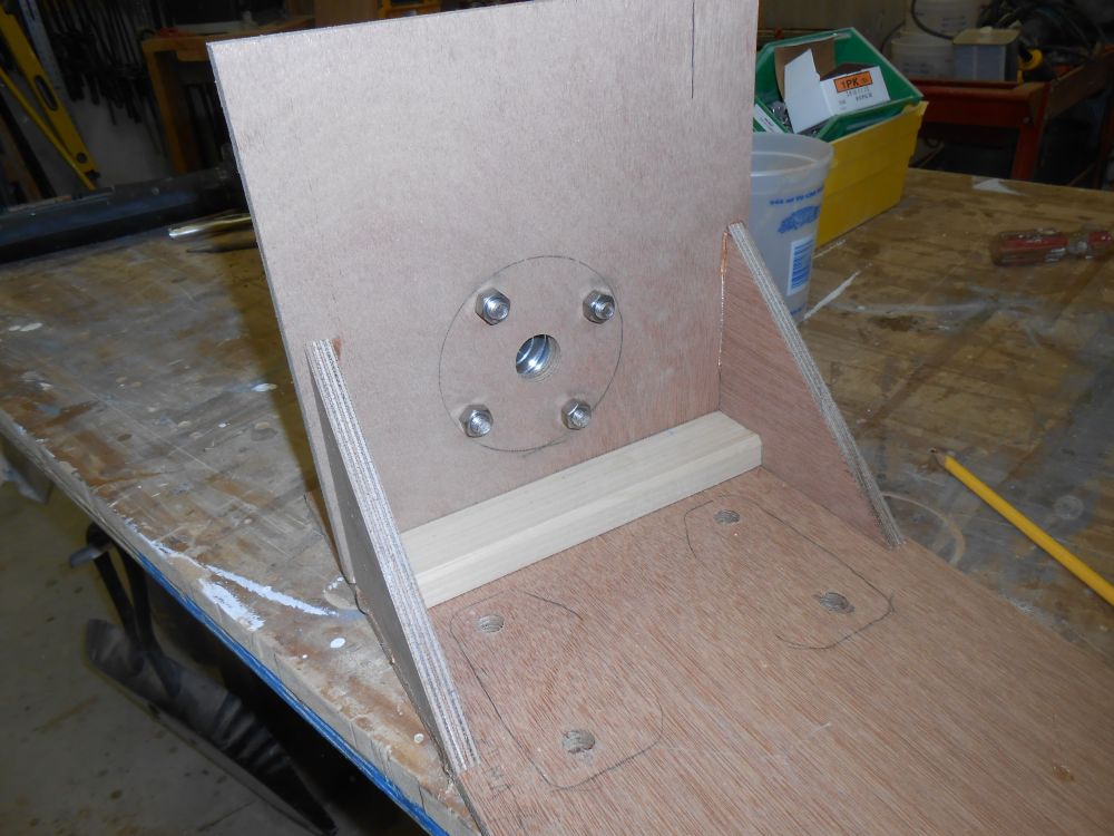
Using a spare shaft coupling that I had on hand, which happened to be of the same size and bolt pattern as the transmission, I marked and drilled bolt holes, and checked the alignment of my new vertical piece with the transmission coupling. Then, I removed the motor from the platform and secured the vertical piece in its stead, mounting it just forward of the line on the plywood to indicate the face of the coupling and bracing it to remain vertical. I bolted the spare coupling to the plywood on the aft-facing side.
So the plywood face to which the coupling was bolted represented the aft face of the transmission coupling for layout purposes, but most importantly, the height of the coupling was properly located so I could align new support platform in the boat with the shaft through its existing stern tube. I could use my template to easily position and start to build the foundation in the correct spot. I accounted for the thickness of the plywood template base in my plans and mental design. More on all this as it happens.
Total Time on This Job Today: 8.5 hours
