

|
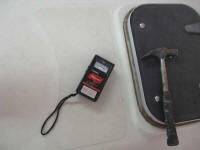
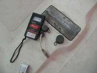
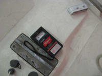
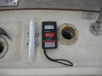
Equinox Project | Monday, December 1, 2008 The first order of business as I got down to brass tacks was to determine the actual condition of the decks and their coring, so as to determine what course of action was required for repair--or not, as the case might be. Cosmetically, the decks were in fair condition, and the owner hoped that it might be possible to save the molded nonskid pattern. This, coupled with the generally restorable condition of the decks' original gelcoat (overall in good condition, but dirty and oxidized), meant that there was a good chance that there would not be a need--nor desire--to repaint the decks as part of this project. However, there was some evidence of the possibility of debonding, top-skin delamination, and deck core issues and, while I was aware of the possibilities, I had not yet had the opportunity to truly delve into the structural aspects of the deck. During earlier inspection tours, my impression of the deck had been that it seemed sound and solid underfoot, with some minor creaking and crackling that could be a telltale sign of core or debonding issues, or could have been inherent with the basic construction techniques used by the boat's builder--that is, that the interior bulkheads were not tabbed to the deck, but were mechanically-fastened to molded ridges in the liner, thereby allowing certain amounts of movement and the resultant friction that causes creaking noises. To begin, I dusted off my surveying tools, metaphorically speaking, and sounded the decks with a steel hammer to determine the location of any voids, debonding, or other structural issues. Sounding results generally revealed no particularly alarming areas of note, though overall the entire deck surface lacked the clear, hard ring associated with certain types of sound deck construction. But the overall results were consistent, with only a few areas indicating something otherwise. Despite initial worries, I didn't find much with which to be overly concerned. As I moved along, I also used a
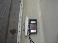
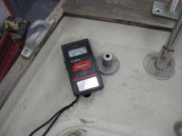
moisture meter over the entire deck, after first establishing a baseline
measurement on several areas of the solid-glass hull for reference
purposes. I was pleased to find that in nearly all areas, moisture
readings were at the low to nonexistent end of the normal expected
range, with only a few specific areas showing anything higher than this.
Most notably, the area just aft of the stem, in way of the bow pulpit
bases and some through-bolted U-bolts for the lifelines, showed higher
readings well into the "red" zone (a relative measurement only), which
wasn't a complete surprise. However, these elevated readings
appeared to be isolated to the areas directly adjacent to the hardware
in question, and nearby deck areas were observed to contain normal
readings. I've included photos of the areas in question below,
with further description as appropriate. |
||
 Coachroof aft of the saloon hatch |
 Mast step--no issues |
 Mast step |
 Port poop deck |
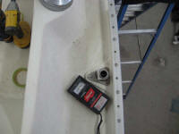 Possible slight moisture elevation at port aftermost stanchion base |
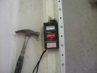 Port chainplates |
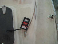 Port forward jackline bolt--dry |
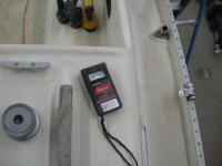 Port aft jackline bolt--dry |
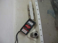 Port midships cleat/stanchion base |
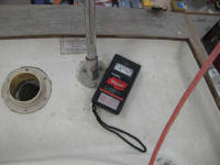 Port stern pulpit base (aft) |
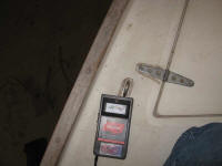 Port lifeline bolt (at bow pulpit)--elevated moisture here |
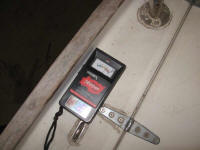 Port lifeline bolt--moisture continues forward |
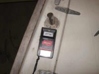 Aft of port bow pulpit base-- elevated moisture readings |
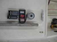 Port cabin top winch/stopper--dry |
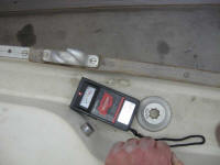 Outboard of starboard coaming |
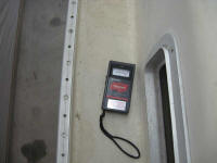 Starboard sidedeck--slight top-skin delamination and minor elevated moisture |
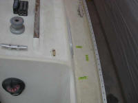 Area described in the last photo marked off and seen from a distance |
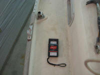 Starboard sidedeck forward of mid stanchion base |
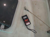 |
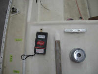 |
 |
 Starboard poop deck |
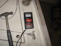 Starboard foredeck aft of pulpit base--elevated moisture readings, similar to port side |
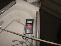 Just forward of the starboard bow cleat, the elevated moisture readings end |
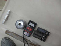
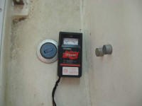 Left--starboard cabin top winch and stopper | Right--Water tank fill plate |
||
|
With the deck inspection complete, I decided I had to take advantage of the opportunity to clean the decks, which featured an accumulation of dirt, dust, and debris from the boat's storage during the months prior to the project. I gave the boat a quick wash and wipe-down, which greatly improved the deck's appearance and which would better prepare things for the future steps, whatever they turned out to be. |
||
|
Afterwards, I began to remove deck hardware, all of which required rebedding regardless of how we decided to proceed on the decks. To help confirm my impressions and the results of the deck's survey, I began removing hardware at the stem, with the after pulpit bases and the lifeline u-bolts, which were accessible from the V-berth. I also removed the forward bow pulpit bases, which were screwed into a cast aluminum stem piece. The two bow cleats, located a bit further forward and on the far side of the forwardmost interior partition, were not accessible from inside thanks to the boat's full molded deck and hull liner configuration, most notably the protrusion of the molded foredeck anchor well, which greatly limited potential reach and movement in the confines of the pointy end. So I left these cleats in place for the moment. |
||
|
Continuing aft, I addressed the forward stanchion bases, located near the aft end of the V-berth. I've often said over the years that boats containing full molded liners create efficient production for the builder, but are a disaster for future maintenance and upgrades that might occur many years later. In this particular case, the underside deck liner ended an inch or so shy of the edge of the hull, and featured a molded area intended for some wooden trim pieces, which had been removed by the owner much earlier (and were now in storage at the shop). The area beneath this trim piece protruded over the nuts for the stanchion bases, but since the area wouldn't be seen once the trim was reinstalled later, I decided to cut away a small portion of the liner in way of these stanchion bases--partly out of requirement in order to access the inner nut, and partly to allow installation of a backing plate later, when I reinstalled the hardware. Currently, the stanchions featured no backing plates or, in at least one instance, even washers. After a failed attempt to use my Roto-Zip tool to cut out the liner here--the tool was too tall to fit in the space available beneath the deck--I used a grinder with a cutoff wheel to carefully make the cuts. Even by extending the cut as far out towards the molded lip defining the edge of the trim section, I still couldn't remove enough liner to fully observe and access the innermost nut securing the stanchion base, but it was enough to get it unscrewed in any event; I'd deal with the limitations of the access further later on in the project. For now, I moved on to repeat the process on the opposite side of the boat, releasing both forward stanchion bases. |
||
|
Next, I wanted to remove the chainplates--three on each side, with the aftermost set accessible through some lockers located above the galley port and starboard. The forward two sets were hidden behind various plywood interior panels, so before I could continue I needed to remove these for access. Besides the pressing need to properly bed the chainplates, we also faced the likely replacement of the chainplates themselves as part of a partial re-rigging project, since someone had overbored the chainplate pin holes to accept the 1/2" clevis pins used by the upsized 1/4" stainless steel rigging. In addition to these holes being too large should we decide to reduce the rigging size (which would then use a more appropriate 3/8" clevis pin), the larger holes cut into the width of the material remaining in the chainplate around the pin holes. According to Skene's Elements of Yacht Design, 8th edition, there should be a minimum 11/16" radius to the top of the chainplate, beginning at an imaginary point 1/8" above the center of the pin hole. On Equinox, I measured about 5/8"--not terrible, but less than it should be. In any event--any final discussions and decisions regarding the rigging choices notwithstanding--these concerns were behind the requirement for removal of the chainplates. Somewhat amusingly--at some point one stops being perturbed and the situation becomes laughable rather than bothersome--this led into far more work and disassembly than I'd counted on, as well as substantial head-shaking on my part. Read on. |
||
|
I began to starboard, in the area behind where the head had once resided. Here, there was a small AC shore power panel and old AC battery charger, so I started by removing those and un-securing the bundled wires hither and thither as I went. Eventually, I removed the plywood panel, revealing the chainplates behind. The forward chainplate was easy to get to, but I was amazed to find that the interior bulkhead--the one defining the forward end of the galley on the starboard side--prohibited access to the nuts on the after chainplate. The only way I could remove the chainplate was to remove this bulkhead. |
||
|
The bulkhead appeared to be secured to the various parts of the hull and deck liners with a series of exposed screws around its perimeter; I hoped that there wasn't any sort of adhesive too, though I didn't expect to find any. Still, one never knows, and it's always prudent to expect the unexpected. Before removing the bulkhead, I had to remove more of the wiring--all of which was going to come out anyway, so that was not a big problem--and a couple small trim pieces. Then, I unfastened the visible screws and prepared to remove the bulkhead. Clearly, it was loose, but it seemed to be stuck in the lower corner. Examining the solid wood trim at the inner edge of the bulkhead, I found a series of plugged fastener holes. Apparently, despite the presumably removable nature of this (and other) interior bulkheads, the builder had decided that long screws securing the trim--which then penetrated the fiberglass galley unit directly behind--were necessary. So I carefully bored away the plugs hiding the screw heads (using a Forstner bit and then an awl to scrape away the final detritus), and removed the five offending 2" pan head screws. After this, the bulkhead came right out. |
||
|
With the chainplates finally exposed, I unbolted them with relative ease and pulled them out, marking each for future reference. Next, I turned to the chainplates on the port side. Again, I began by removing some smaller panels located inside the hanging locker, exposing the chainplates. I found a large pile of shredded paper here, likely left by some former resident. I saw no other evidence of rodents (so far). |
||
|
I noticed that once again the after bulkhead limited access to the after mid chainplate's nuts. Since it seemed likely that I'd also have to remove this bulkhead, I examined the adjacent cabinetry to see how it all came apart. Once again, the thought came to mind that needing to disassemble the entire boat just to access three bolts was indicative of a construction technique that was more than a little bewildering and shortsighted, but I brushed the thought aside and reached for the screw gun. There was a series of screws inside the outer panel of the hanging locker, but it looked like I might be able to remove the whole thing by taking out a half dozen exposed screws located on the forward side of the v-berth bulkhead. I removed these, as well as the screws securing the aft end of the hanging locker panel, and this released the panel--mostly. Once again, I found myself on my hands and knees looking for the secret fasteners. This time, I located a large plug at the base of the solid teak trim--a plug large enough to seem indicative of a through-bolt rather than a screw. Opening the forward bilge hatch, I found that indeed the base of this trim was secured to the liner with a single bolt. Why, in an interior composed of screwed-in, cosmetic partitions, the builder found a need to bolt this one insignificant area was beyond me, but I removed the nut and carefully tapped the bolt out, forcing the plug out (reserved for reuse) in the process. Then, I removed the panel, finally. |
||
|
By now, it was late in the day, the sundry interior disassembly having extended the chainplates' removal time by far longer than I ever though possible, and rather than immediately remove the aft bulkhead, which partially blocked the chainplate bolts, I found that in this case, there was just enough room to slide my wrench in and onto the nuts, after which I could remove the bolts. I'd have to remove the panel later, to allow for reassembly of the chainplates, and since the panels were coming out anyway I figured it would make cleaning and refinishing the panels far more efficient and straightforward, but it saved me several minutes now to avoid its removal, allowing me to finish the job that I'd hoped to complete before the end of the day. |
||
|
||