

|
Circe
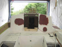
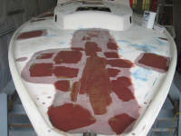
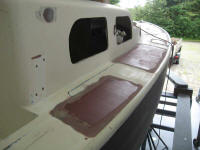
| Wednesday, August 12, 2009 Once again, I began the day by sanding the various deck patches, and cleaning up afterwards. Most of the smaller areas (i.e. filled hardware holes) ended up nearly sufficiently fair afterwards, so for those areas I applied a thin third coat of filler, this time using the fine Alexseal fairing compound. |
|
Most of the recored patches were becoming close to fair after two coats, so I longboarded as needed to determine the low areas requiring additional fairing compound and concentrated on applying the material to those areas. |
 |
|
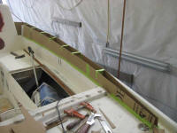
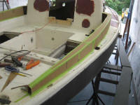
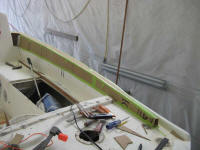
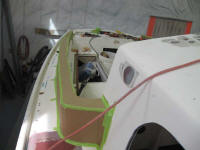
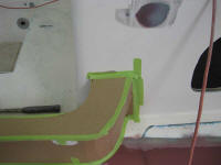
With the sanding and fairing portion of the day's work behind me, I worked again on the cockpit coaming mockup, this time on the starboard side. I wasn't satisfied with the port side mockup, even overlooking the crooked and rough contours of the cardboard I'd used. After some consideration, I decided to lower the height of the coaming on the starboard side by an inch at each end. In addition to reducing, obviously, the height, this change would have the effect of creating a slightly wider top surface (since, with the angled sides of the coaming, the lower it was, the wider the top would be), and also reduced the overall bulk of the coaming in relation to the adjacent parts of the boat. I built the starboard mockup in the same manner as the port, though this time I added several additional interior braces to help the flimsy cardboard better retain something resembling a smooth curve as I bent it around. I hoped this would help the overall appearance of the mockup. I could envision what the finished coaming would look like, but unfortunately the mockup didn't quite look like this internal vision, but it was close enough for what it was for. |
 |
|
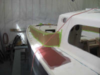
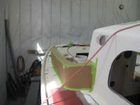
After completing the starboard coaming, I felt that the lowered profile was more successful than the higher port side, and briefly considered rebuilding the port mockup to match, but decided it wasn't worth the time since the higher mockup didn't really affect the general feeling of how these coamings might work on the boat, and the starboard side was in place to better visualize the actual height. Still, it bothered me that the two sides were at different heights, but I suppose you'll just have to excuse me. Note that the cardboard returns on the coamings, at the forward ends, are not intended to be completely representative of the final shape, but are more bound by the ability of the cardboard to bend. |
  |
|
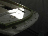
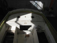
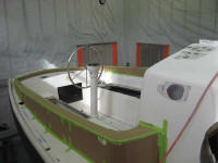
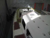
To complete the coaming mockup, I created an aft coaming running between the two sides, and following the curvature of the transom that I'd laid out earlier. Because the side coamings tapered to 1-1/2" in width at their aft ends, I built the curved aft coaming 1-1/2" wide to match, though I considered making it wider, but discounted the thought in favor of aesthetic consistency with the adjacent pieces. Note: the port coaming is 1" taller than the starboard. The aft coaming is constructed to match the starboard height, and therefore is not flush with the top of the higher port coaming. The starboard side is the proposed height. Sorry for the dark photos. |
 |
|
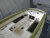
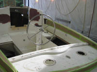
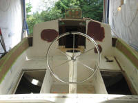
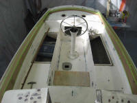
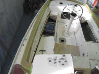
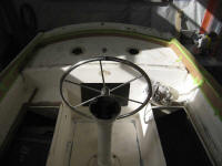
To complete the mockup, I planned to build an approximation of the steering pedestal and wheel. I was looking for online guidance for dimensions of these items when I realized that I had an old pedestal upstairs in storage: what better mockup than the real thing? So I fetched it, along with a wheel, and set it up in the cockpit. The position I chose for the moment, just forward of the existing rudder post, could only work if the new, raised portion of the cockpit sole, which I'd build aft in the new cockpit extension, ended up at a height that would still make the pedestal workable if one were standing on the new sole. Alternatively, one option I was considering (and still was at this time, for this as well as other reasons that I'll go into when the time is right) was to build a custom pedestal that might adjust the height of the wheel accordingly. Another option was to move the pedestal further forward, allowing one to stand on the existing sole between the pedestal and the raised rudder post; this option, however, had the negative impact of terribly cluttering the cockpit, and I hoped that the after position could be made to work. |
 |
|
Now, for the full effect, imagine, while looking at these photos, that the old poop deck and bulkhead at the aft end of the new cockpit as defined by the cardboard (excuse me, Whitefield Mahogany) coamings was cut out and in its place you could see a continuation of the seating areas to the end, and around the aft curve. Imagine a new sole, raised high enough to clear the rudder post and steering quadrant (for pedestal steering on this boat would require the quadrant to be located above the existing cockpit sole, as no room existed beneath), and extending aft to its natural termination. |
 |
|
Clearly, the proposed changes to this cockpit were significant, and each change brought with it its own set of compromises, from weight distribution concerns to aesthetics to functionality to satisfying the original vision set forth in conceiving these changes. To my mind, there were still issues to be discussed and resolved, but to this end the mockup had certainly done its job in helping to truly envision what the changes might bring about, both positive and negative. The next step would be for the owner to see the mocked-up cockpit in person, after which we could determine what changes to make and how to proceed. Despite the fact that the cardboard mockups did not smoothly bend to the curves I'd laid out on deck, I knew from my layout that I was happy with the exterior curvature of the proposed coamings at the specified width; the final construction could faithfully replicate this curve where the cardboard could not. The lower height of the starboard coaming above deck height--6" at the forward end, 2" at the aft end, compared to 7" and 3" for the port side--was probably a good compromise between proper back support and protection and the aesthetic concerns of the boat. Perhaps, thought I, there might still be an opportunity to cheat the forward end down a bit, but not if it compromised seating comfort. Still, I was concerned that the height and width of the coamings provided excess bulk at the forward ends and the returns to the cabin trunk, something that can't be avoided in this instance thanks to the width of the cockpit opening versus the width of the cabin trunk, and without completely reconfiguring the entire cockpit size and shape. Again, I could visualize the finished product and see that these returns would naturally flow more cleanly into the cabin trunk than in the awkward mockup, but even then there would be a rather abrupt transition, since the coamings necessarily began two or three inches outboard of the edge of the cabin trunk thanks to the set parameters of the original boat's deck design. Also, I felt that the exterior angle on the coamings--more noticeably on the starboard coaming, but also to port--needed to be slightly more (i.e. angle in more towards the top) than the mockups as built. This was an incremental change and such things were to be expected and could only be identified through a physical mockup. Surely other small details would come to light as well. Finally, the exact location of the pedestal steerer remained to be determined based on physical constraints and the owner's ultimate desires. This was of little concern to me in terms of the overall success--qualified or not--of the new coamings as mocked up. For now, the mockup work was complete. Final details would be determined in due course. |
|