
110 Cookson Lane | Whitefield, ME 04353 | 207-232-7600 | tim@lackeysailing.com
Blue Teal | Monday, June 17, 2013
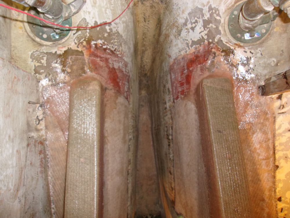
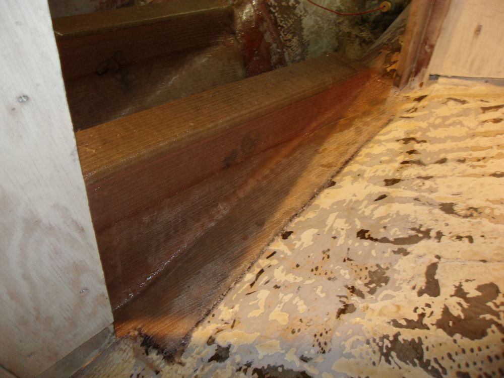
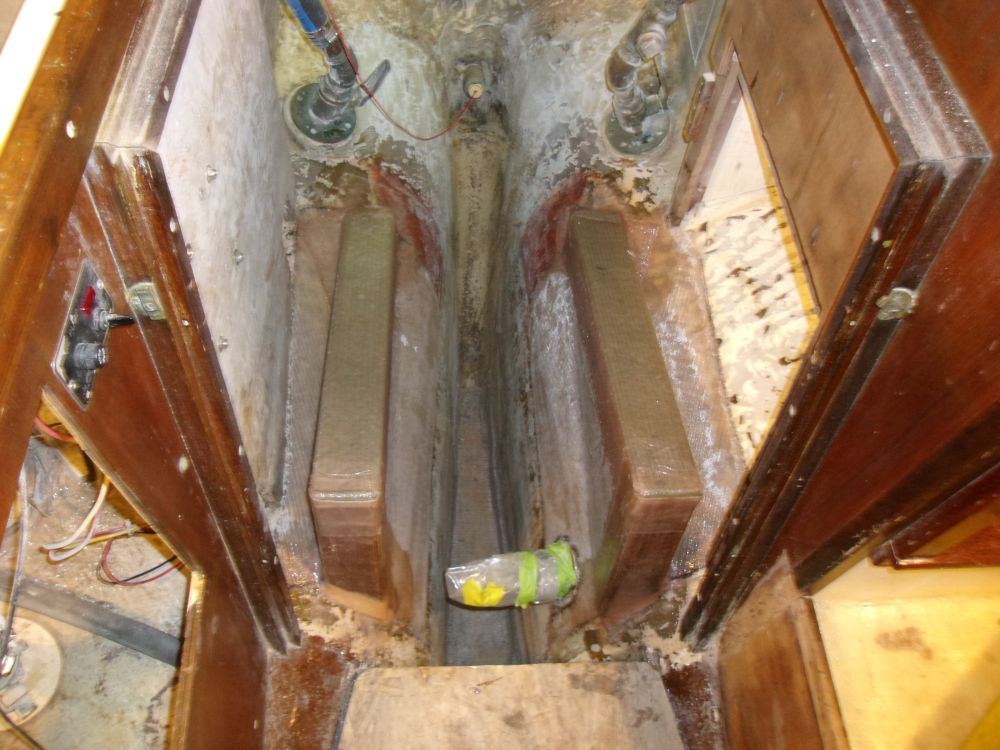
To begin, I water-washed and lightly sanded the new fiberglass tabbing securing the foundations to the hull, removing any sharp edges and preparing the surfaces for the next steps.
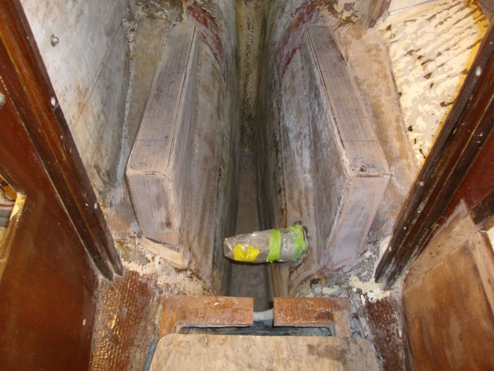
To complete the structural work, I cut two 3" wide, 1/2" thick pieces of G-10 epoxy fiberglass to the proper length to fit on top of the foundations. I'd allowed for this additional height in previous calculations and layout. The dense fiberglass would add strength and durability, and improve the hold of the tapped fasteners I planned for the engine mounts themselves. I rounded the exposed edges to provide a smoother transition for the fiberglass that I'd wrap over the top.
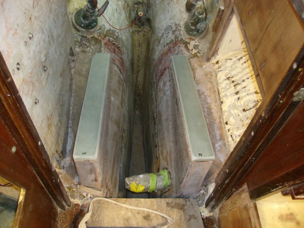
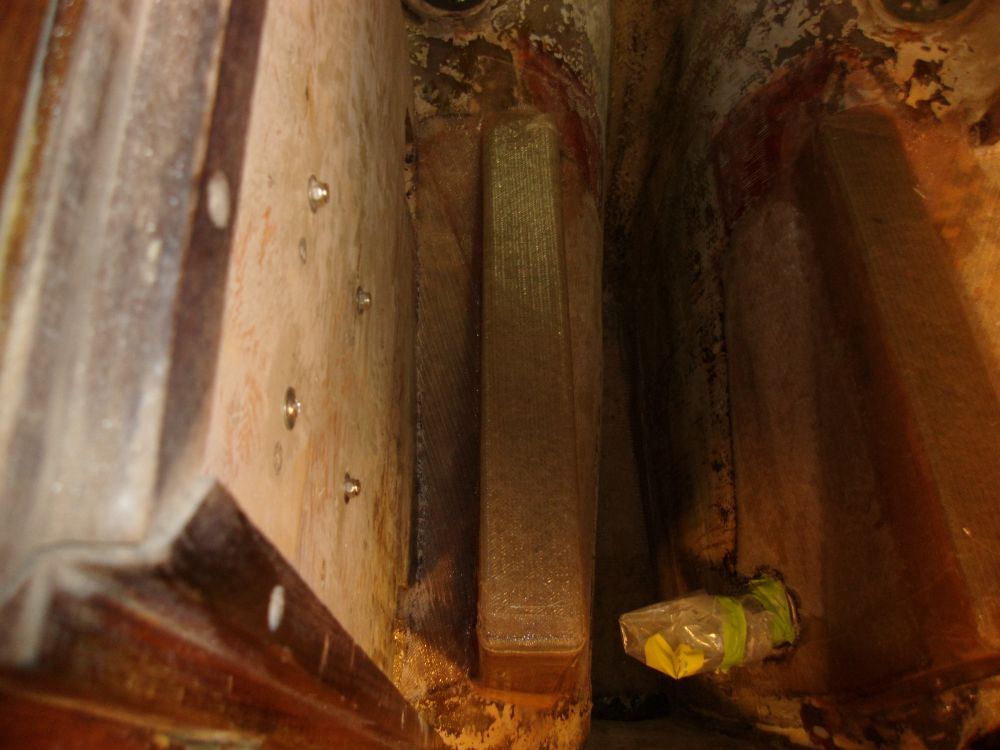
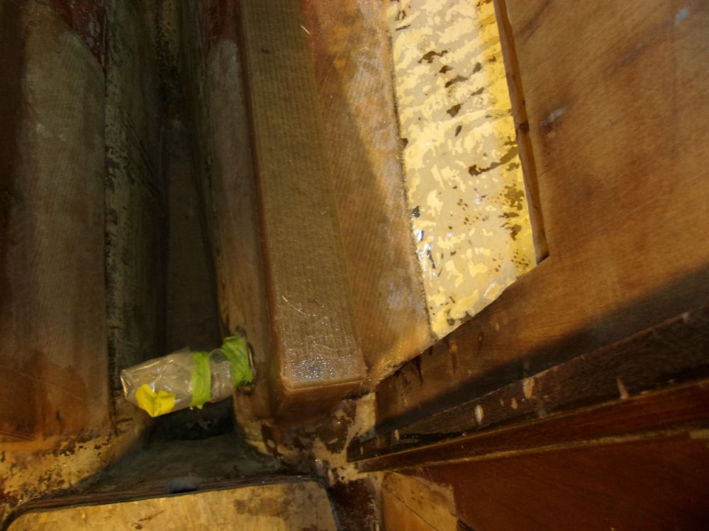
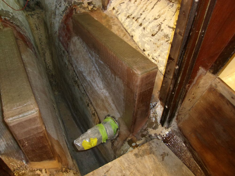
I secured the G-10 to the tops of the foundations with a bed of epoxy adhesive (not shown, sorry), with two screws to hold the product while the epoxy cured. I used excess epoxy to smooth the transitions between the top plates and the foundations beneath, then applied a layer of biaxial cloth over the tops, extending a few inches down onto the sides of the foundations beneath.
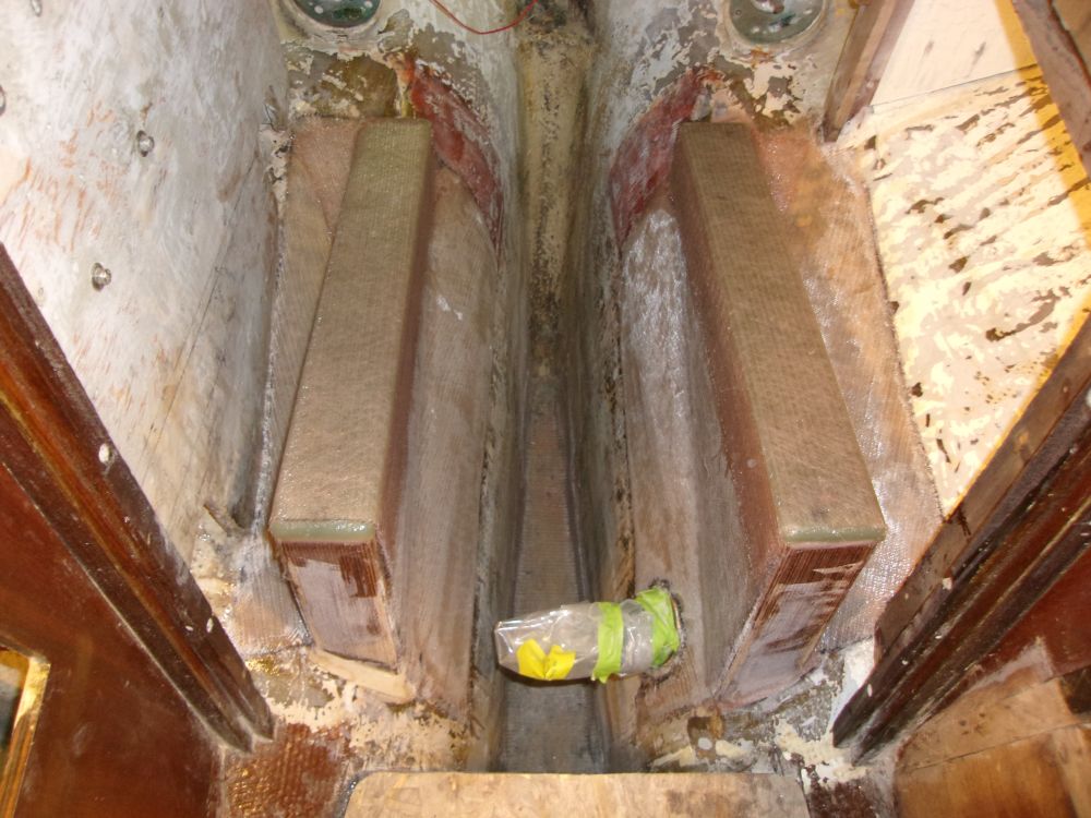
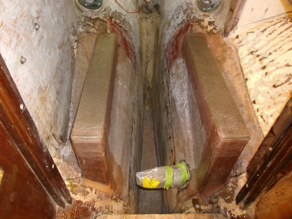
To wrap up the structural work, I applied lightweight cloth over the exposed forward edges of the foundations to encapsulate the plywood, and added smaller bits of the cloth here and there to tie in and cover the aft ends and other areas as required.
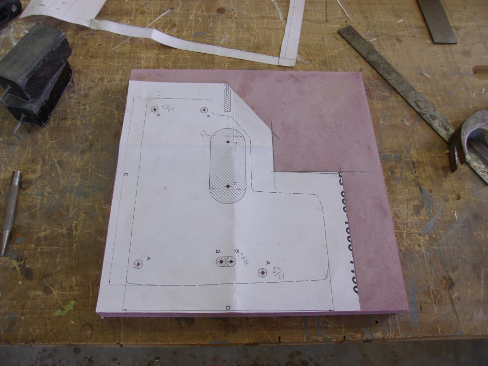
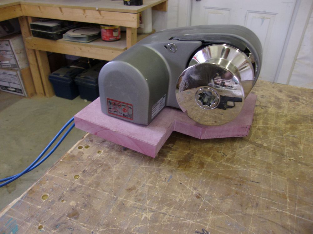
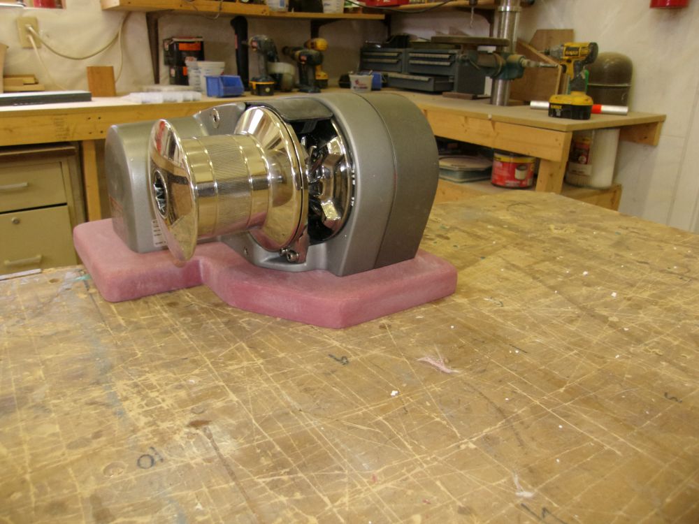
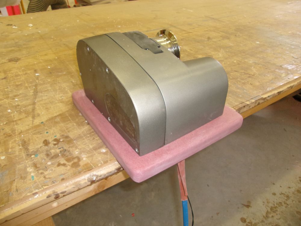
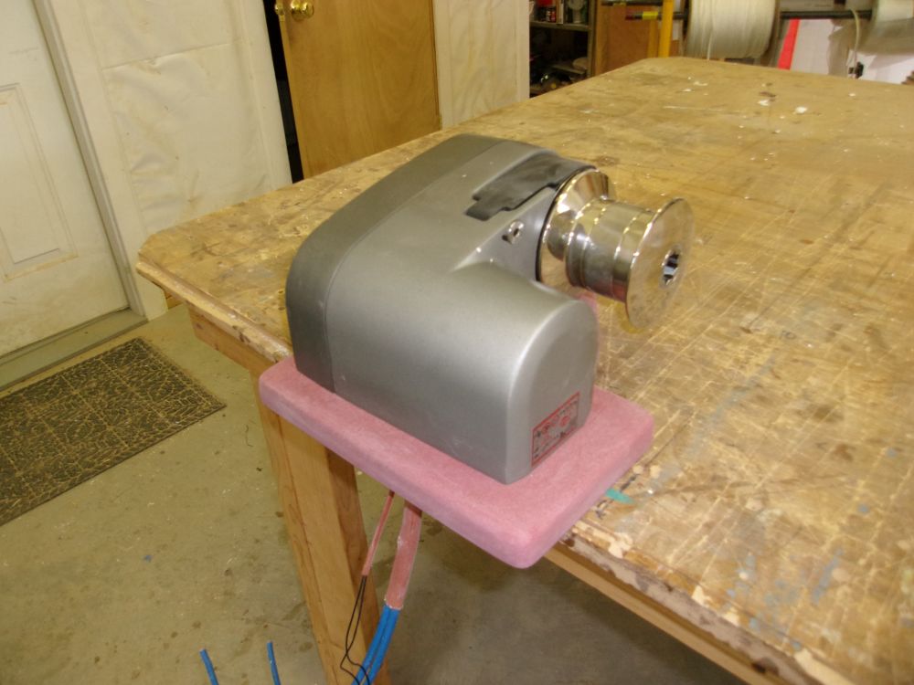
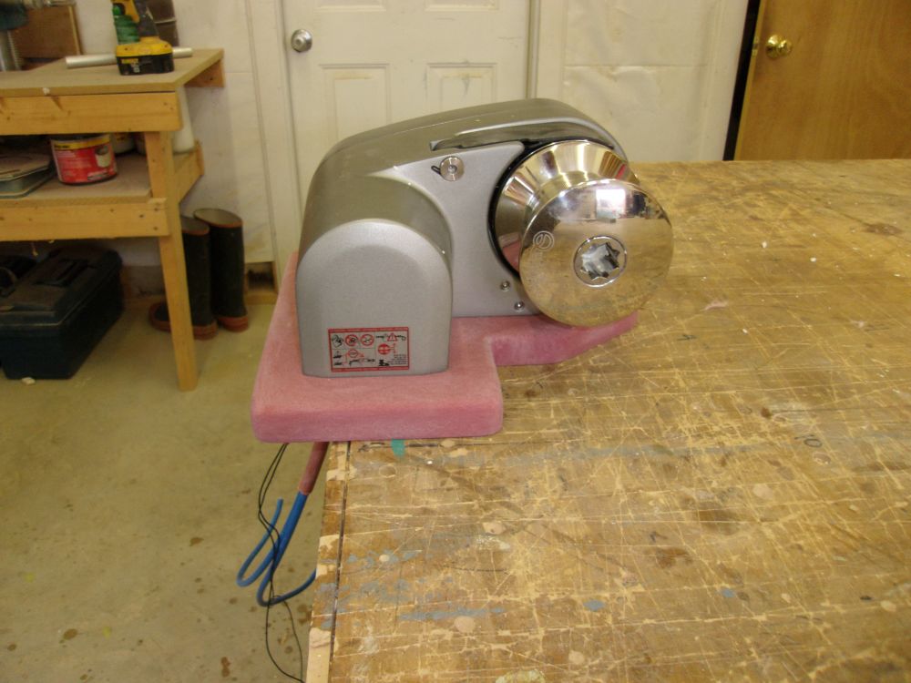
After a meeting at the boat with the upholstery contractor, I turned to the windlass. The owner requested a riser plate beneath the windlass on deck, so to begin I prepared a template of the windlass base, starting with the hole-cutting template supplied with the windlass. After studying the windlass, I decided that the riser plate should be roughly 1" wider than the windlass base in all dimensions, so I cut out the template accordingly, more or less following the shape of the windlass itself but simplifying the shape somewhat. I transferred the paper template to a 12" square piece of 1" thick prefab fiberglass, and marked the outline; I used a center punch to mark the hole locations for drilling, then drilled all the holes first before cutting out the riser itself.
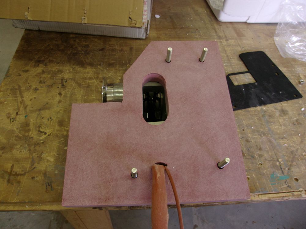
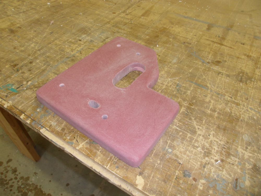
I rounded the top edges and corners, and generally cleaned up and sanded smooth the base plate for better appearance and to prepare it for primer and paint before installation. Meanwhile, I ordered new, longer mounting studs for the windlass itself, as the ones supplied would not be long enough with the riser plate and backing plate I'd be using.
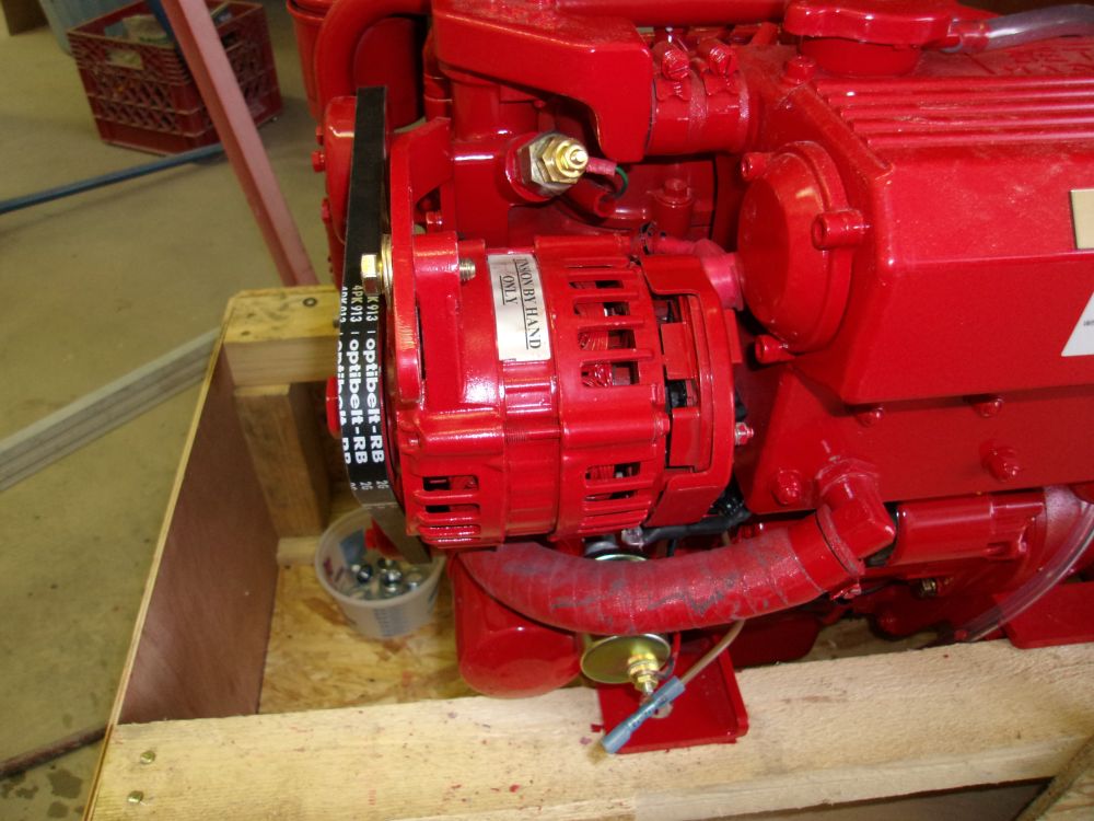
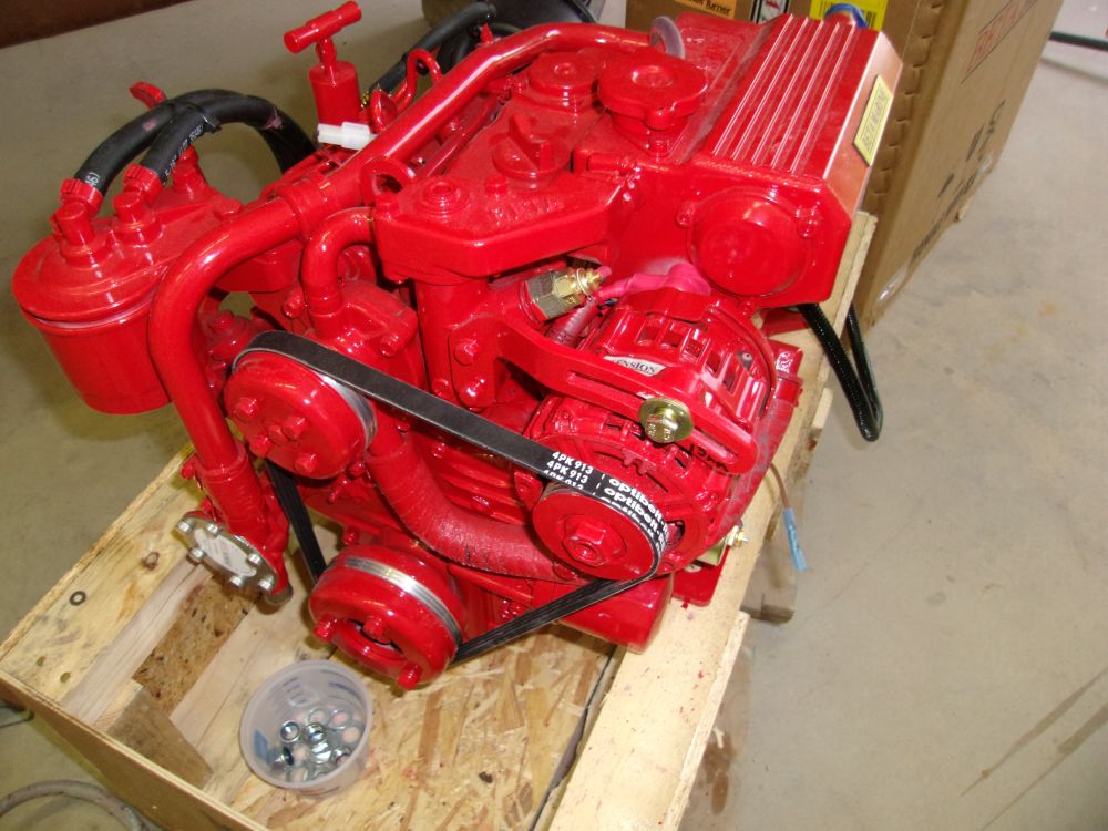
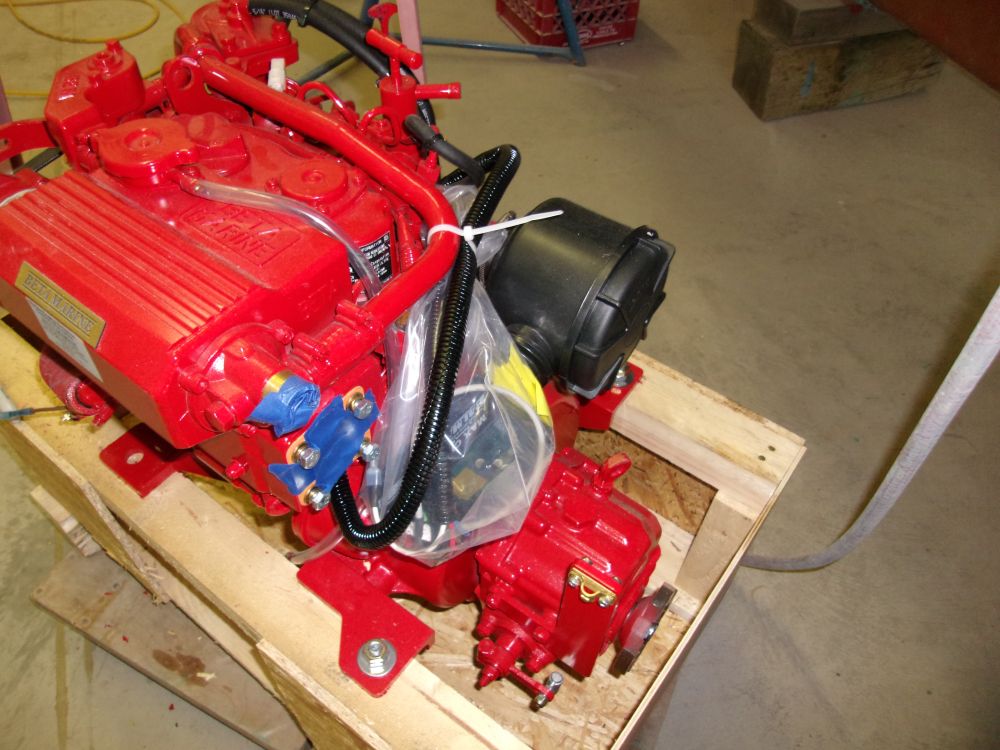
Planning ahead for this project, we'd ordered the new Beta 20 engine well in advance, and it had been on hand for several weeks. Because the owner planned (as part of this project) to have me install a "smart" external regulator, the stock Iskra alternator on the engine required a modification to disable its internal regulator. So before the boat even arrived, I removed the alternator from the engine, and the owner took it to a nearby shop for the modification.
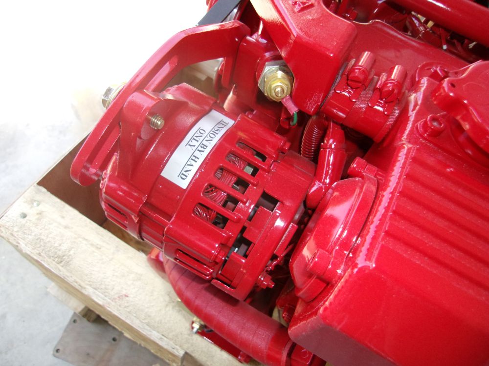
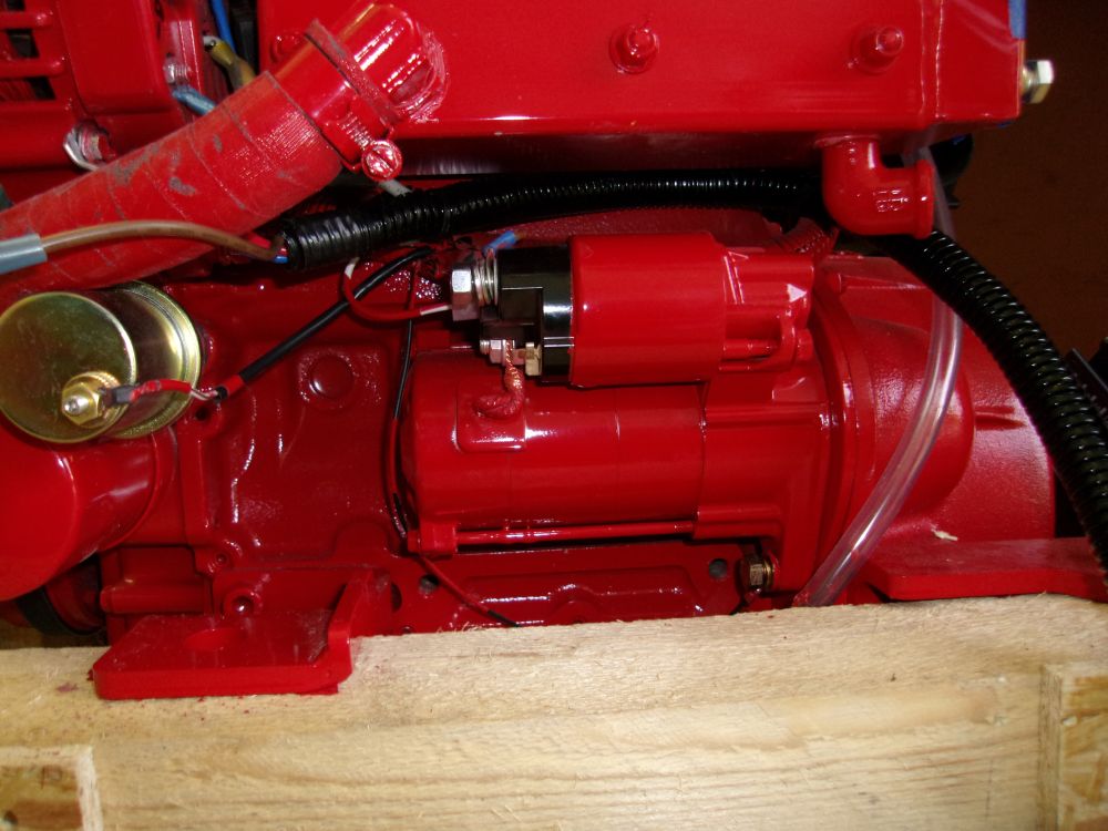
The modification work was complete, and after picking up the alternator I decided to reinstall it while the engine was still on the floor. The alternator shop had pre-wired the regulator to the alternator as required, but I needed to reconnect the original wiring harness from the engine as well. In addition, I installed the wires necessary for an optional alternator temperature sensor that the owner selected; later, I'd also install battery temperature sensors, but they didn't require wiring to the alternator itself.
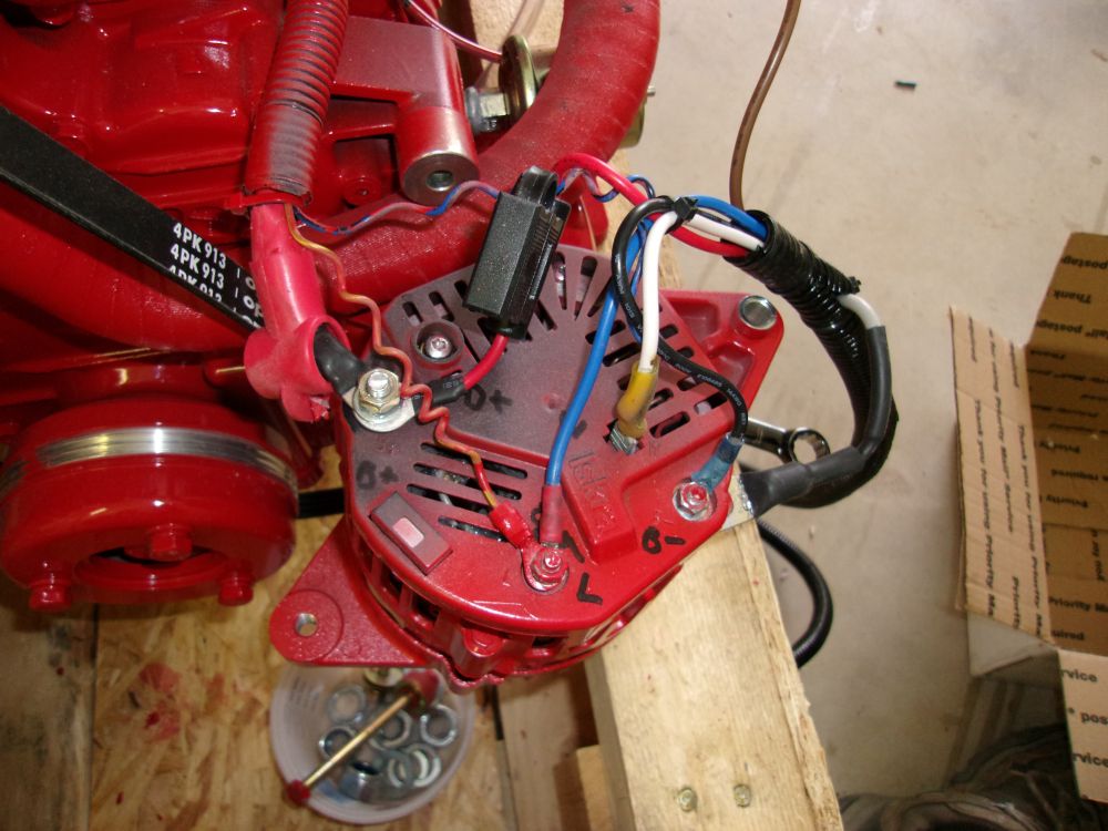
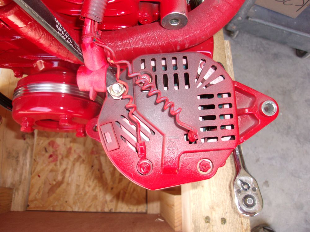
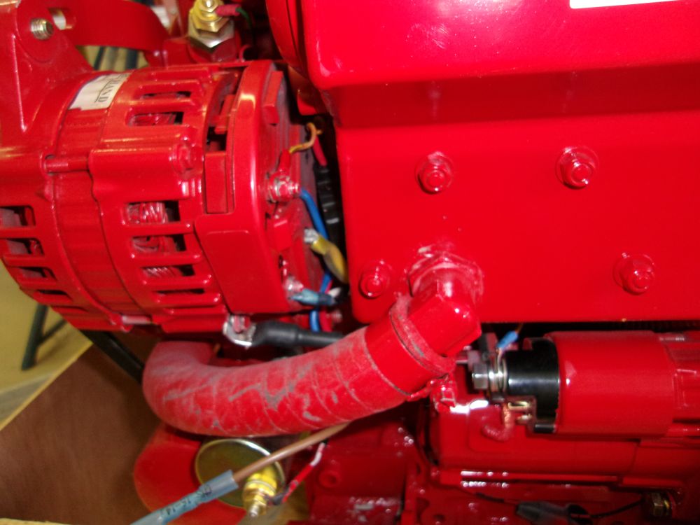
I remounted the alternator with its new wiring, an unnecessarily challenging process that I was glad I'd completed on the shop floor rather than in situ. Other than the tight space available for the wiring behind the alternator, the toughest part of reinstallation was reinserting one of the two spacers required for the alternator's lower mounting bracket. Not only was the space difficult to reach, but there was nothing to hold this spacer in position (I finally used some tape to sort of pre-install it, and a screwdriver from the back (starter) side to align it so I could press the bolt through from the other side), and, to make matters a little worse, the spacer almost didn't fit at all, as the tolerance between the alternator's foot and the bracket/spacers was so tight. The spacer did not have a recessed area to match the protruding bushing on the alternator foot, compounding the tolerance issue.
These photos, taken on the day of the alternator's removal, show the spacers.
Despite the whining over trivialities, I got the alternator reinstalled without any particular trauma (just more time than it should have been), and led the new regulator's wiring harness aft along the engine, where I bagged up and secured the new regulator out of the way for storage till the engine was installed.
Total Time on This Job Today: 9 hours
