
110 Cookson Lane | Whitefield, ME 04353 | 207-232-7600 | tim@lackeysailing.com
Blue Teal | Tuesday, June 11, 2013
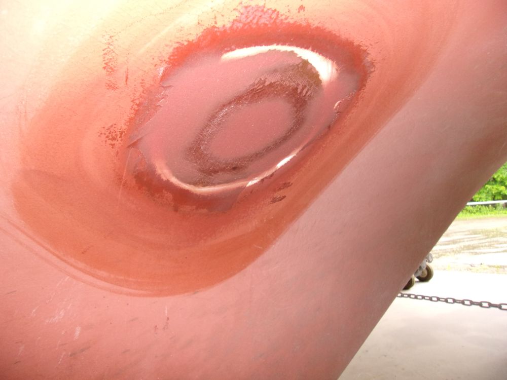
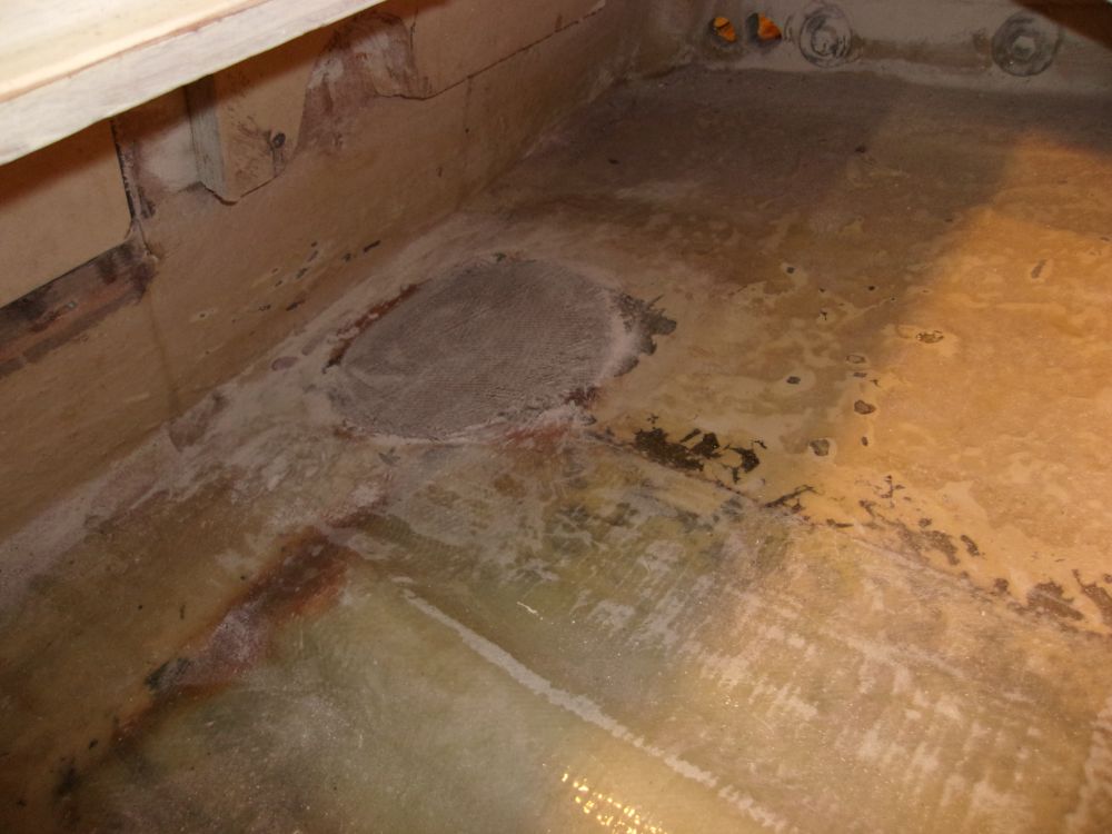
After washing and lightly sanding the new fiberglass patch over the knotmeter through hull, and cleaning up, I applied a light coat of fairing compound to the area. Inside the boat, I lightly sanded the patch as well.
The boat was slightly out of level, so before continuing work on the engine compartment I took a few minutes to level her side to side.
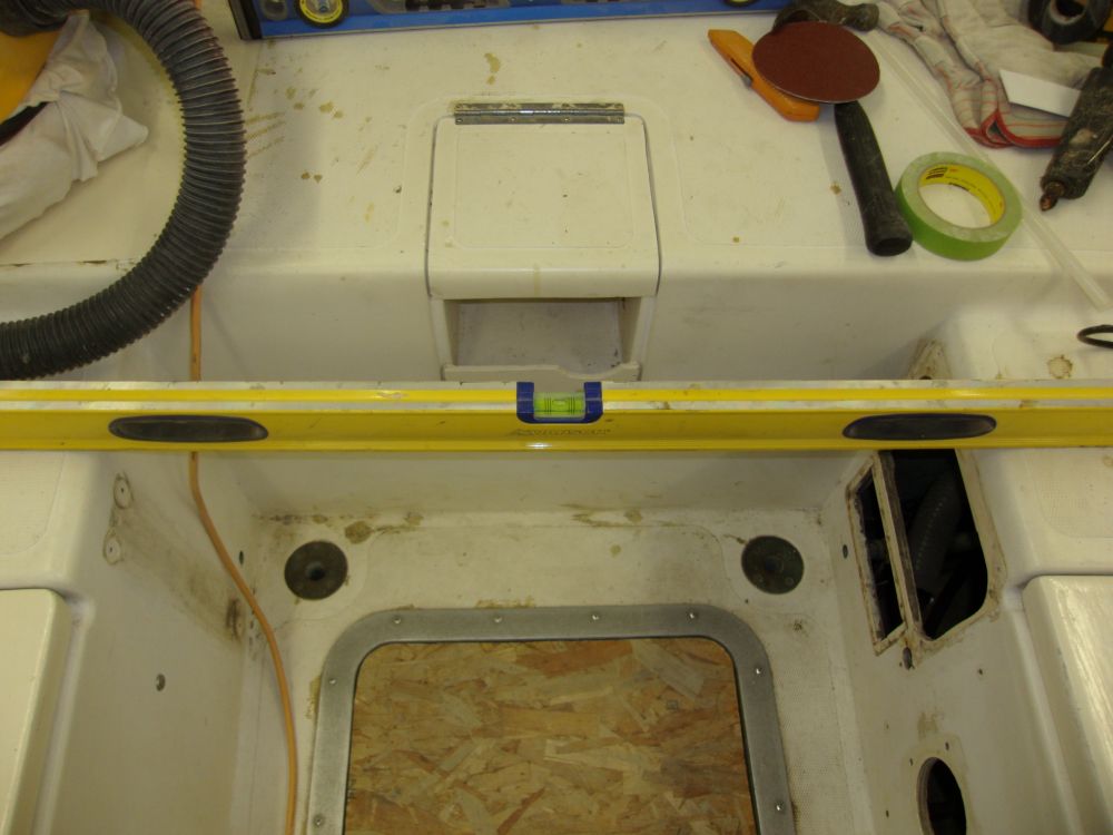
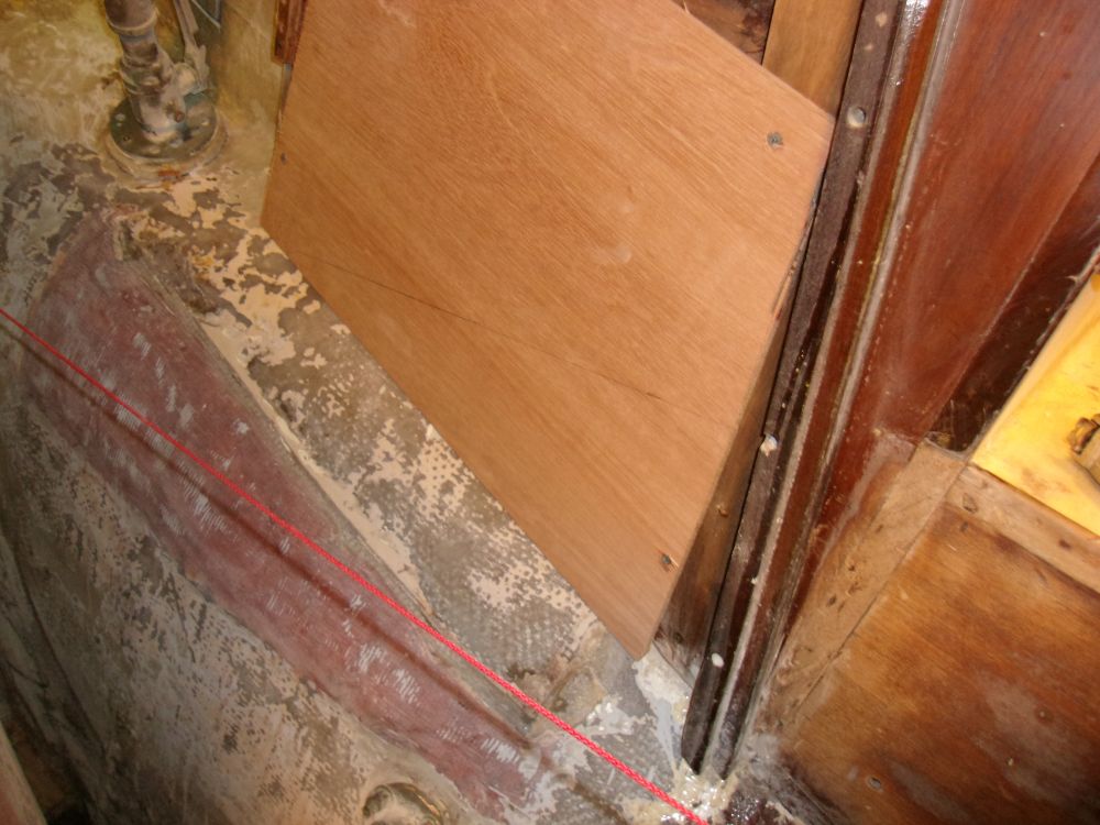
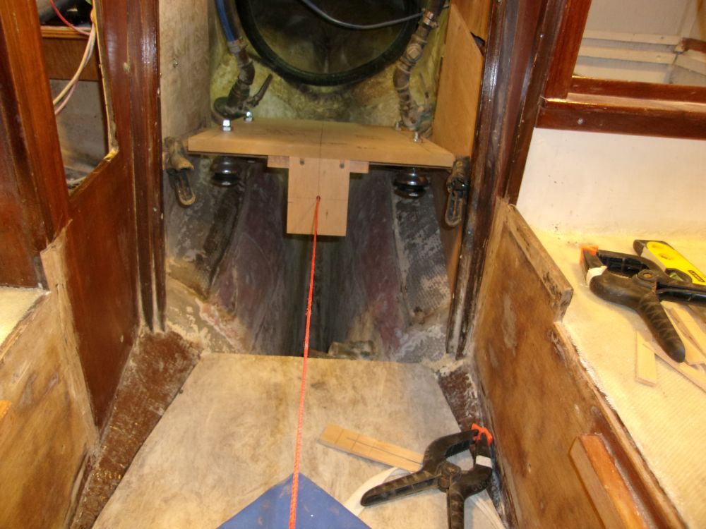
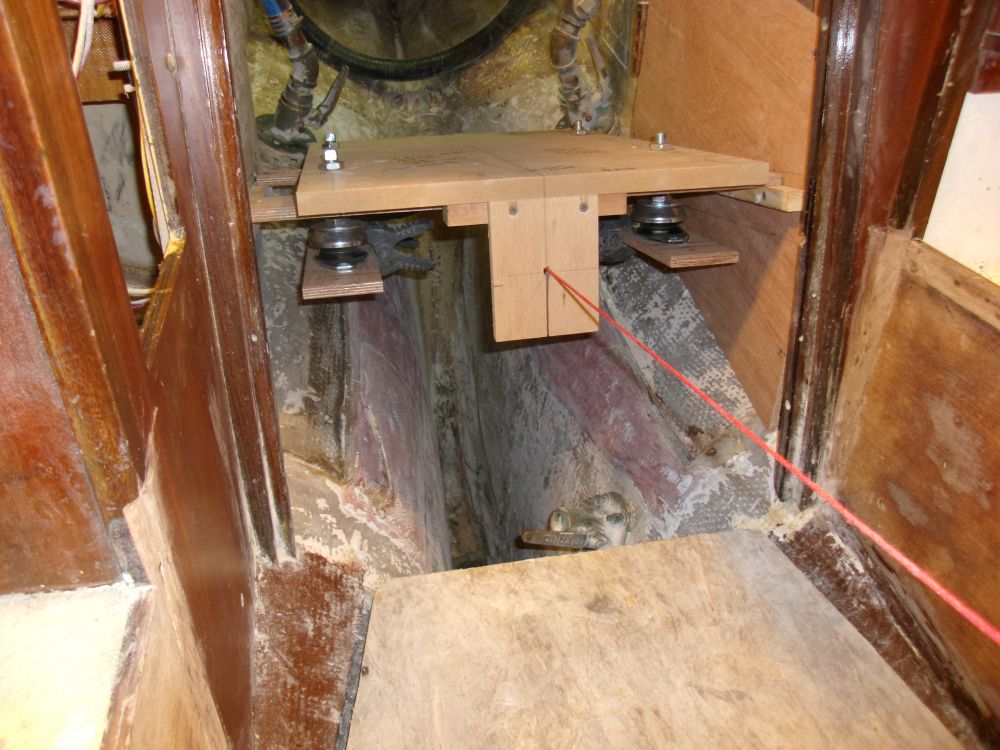
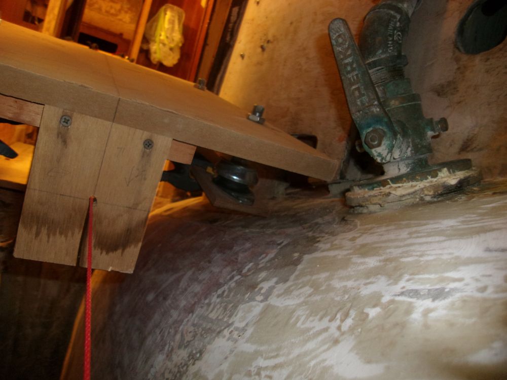
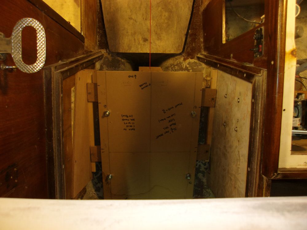
Using a small level and a board, I transferred the position of the shaft centering string, which I'd set up earlier, to the sides of the engine compartment for reference. On the port side, I installed a temporary panel of scrap plywood to give me a layout area, since this side of the engine room was open to the adjacent compartment. All layout related to the engine installations stemmed from the critical shaft centerline.
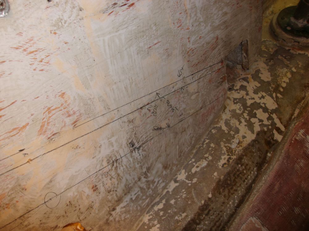
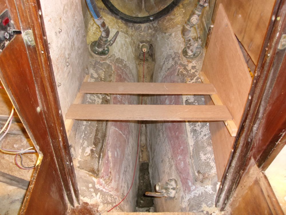
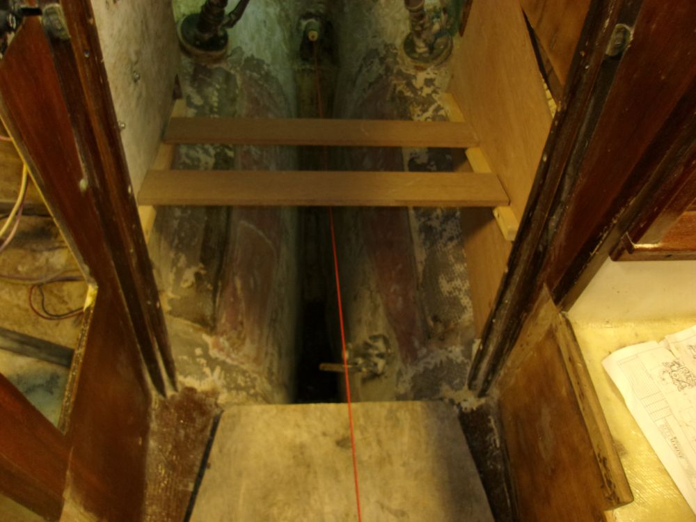
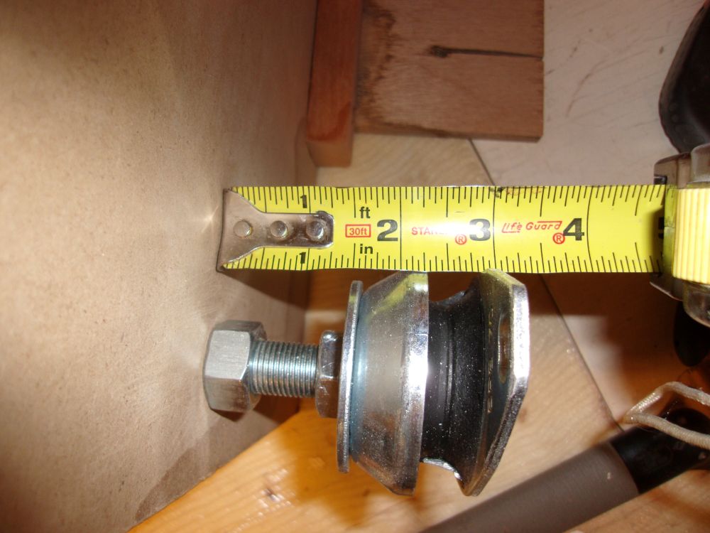
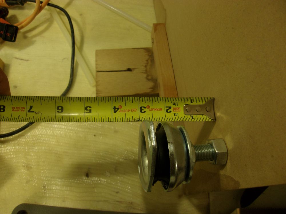
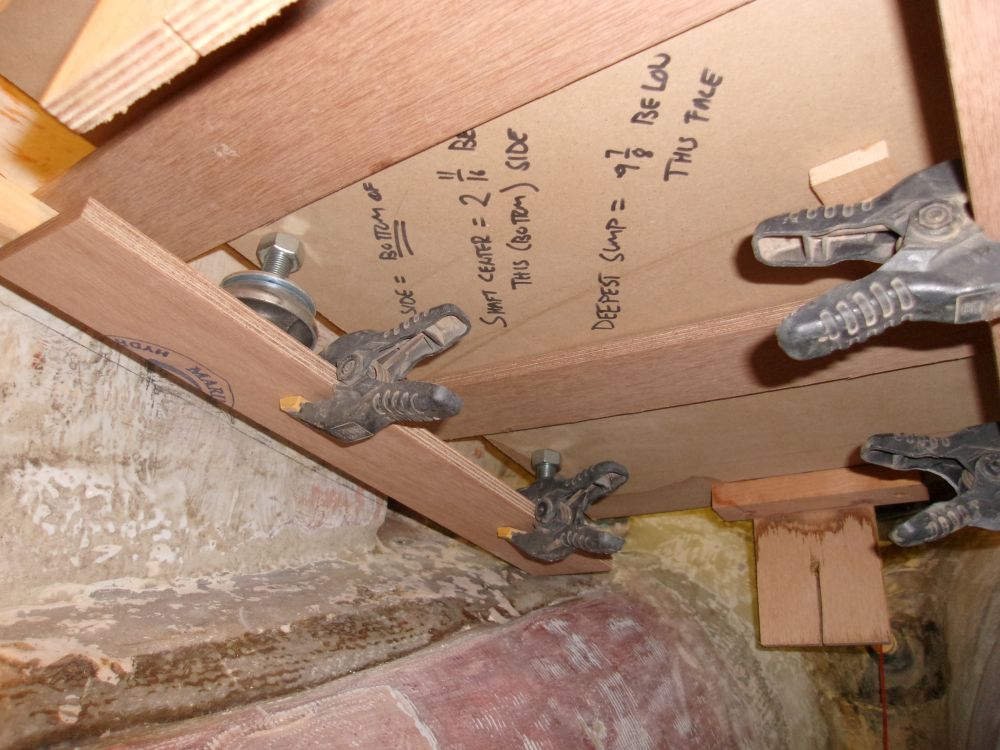
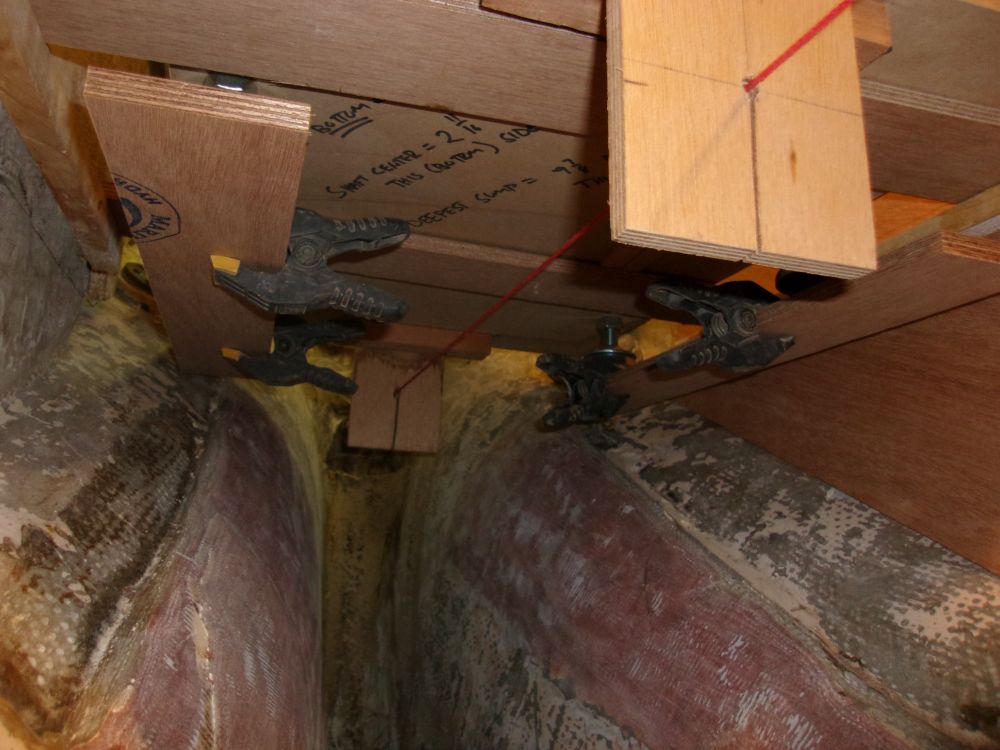
The shaft centerline was 2-21/32" below the level of the engine's mounting flanges, so to allow me to install and support the engine template during the layout, I needed some supports at this level, on which the flat bottom of the template (which represented the bottom surface of the mounting flanges) could rest. So I made parallel marks this distance above the shaft line, minus a 12mm thickness of the plywood scraps I'd run between the sides of the engine room. After installing support cleats on the sides of the engine room, following these lines, I spanned the space with 12mm plywood scraps, the top surface of which equated to the bottom of the engine mounting flanges, 2-21/32" above the shaft centerline.
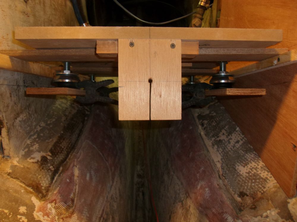
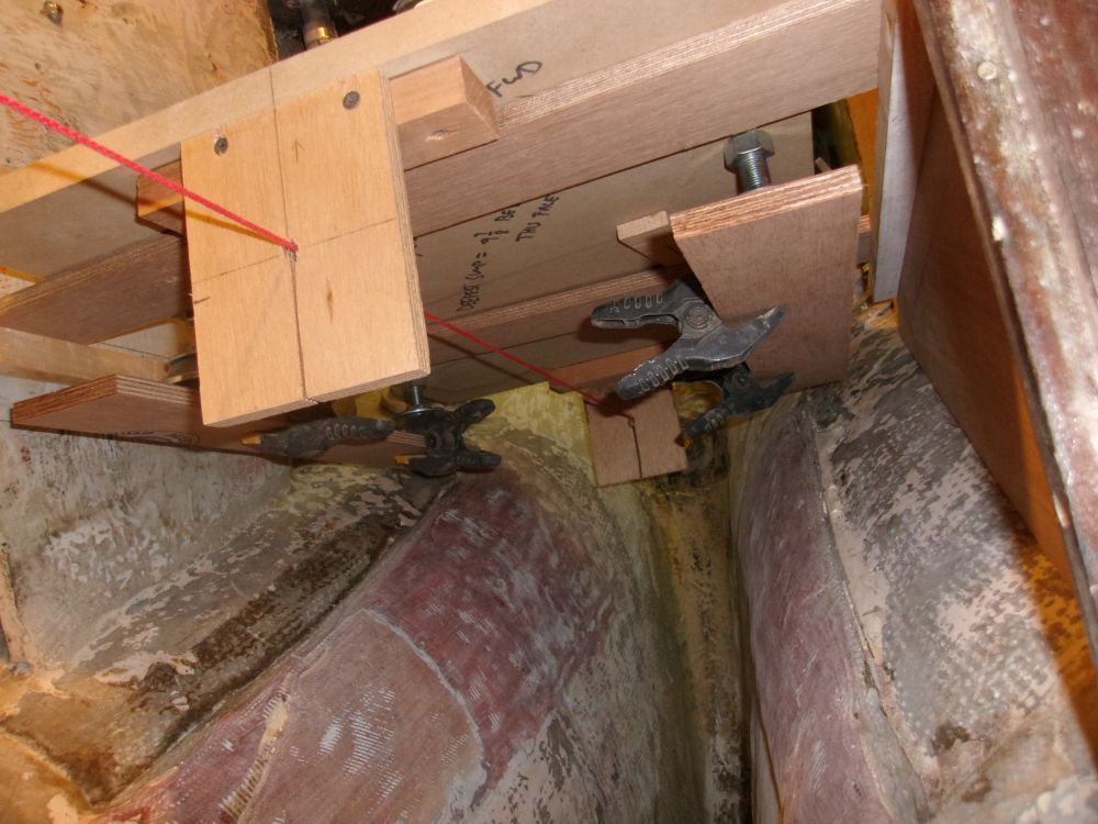
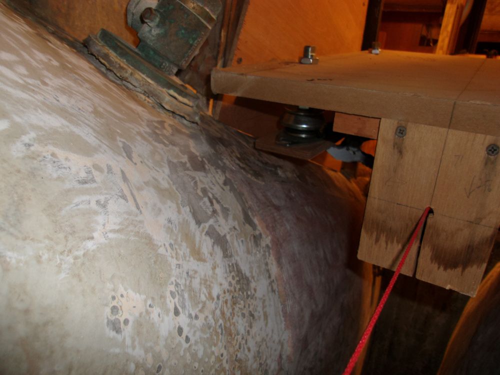
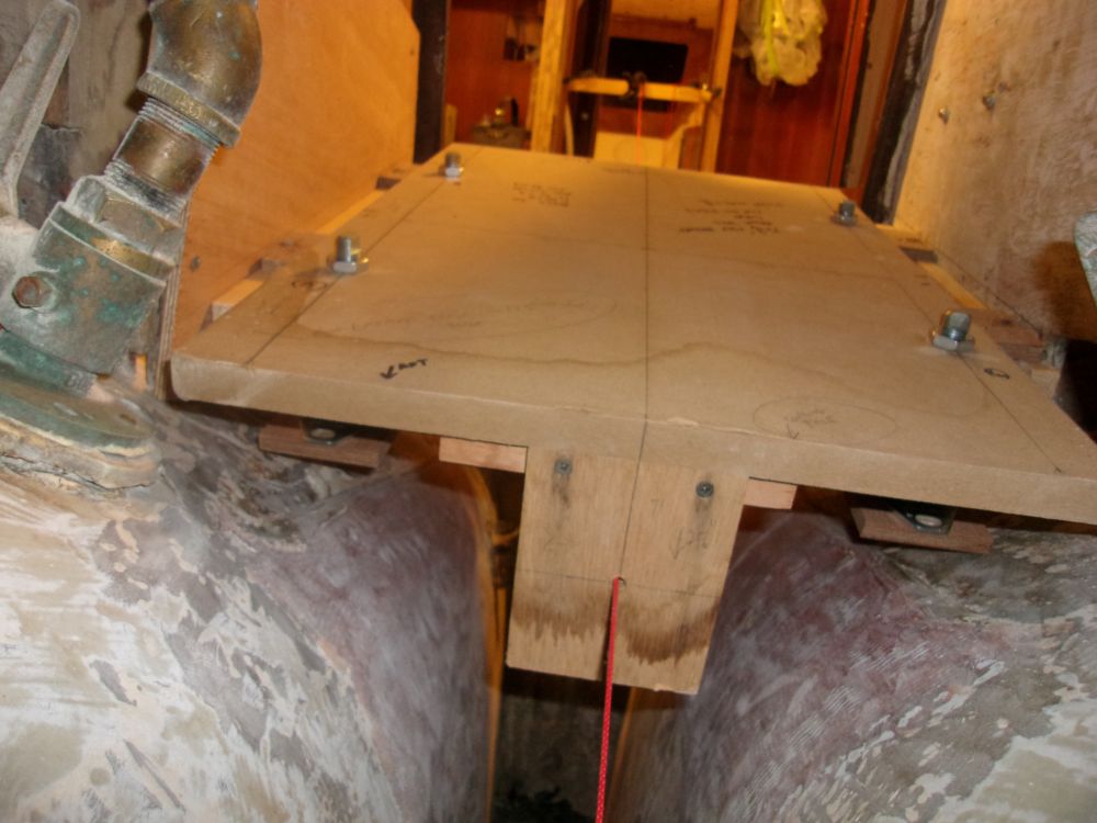
After restringing the shaft center, I set the engine template in position to check its general fit and alignment with the shaft. On the template, I installed the four flexible mounts on which the engine would rest, which hung down below the platform by 3", which was the midpoint of the flex mounts' adjustment range. At this stage, my goal was to get the template and mounts in the generally correct position relative to the shaft line. Final adjustments to achieve the best alignment would wait till a much later stage of the installation. If anything, I wanted the template to be lower than it should be now, to avoid having the foundations end up too high, as it was always easier to add height than take it away.
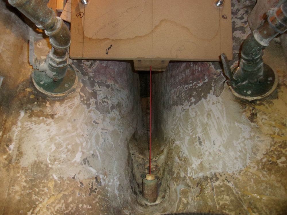
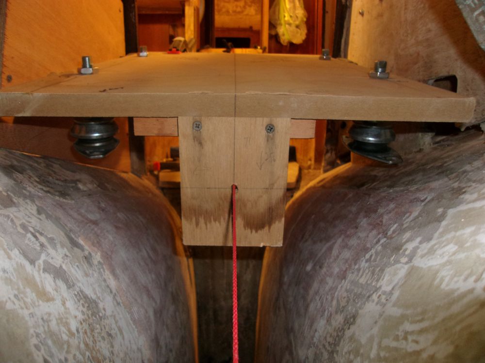
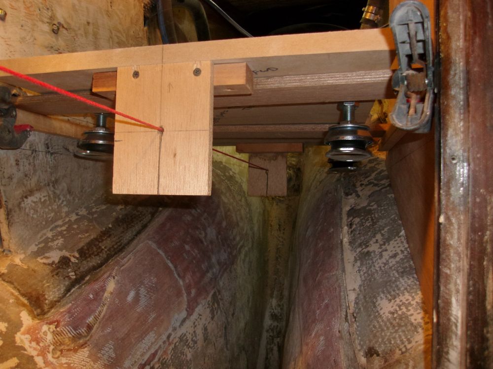
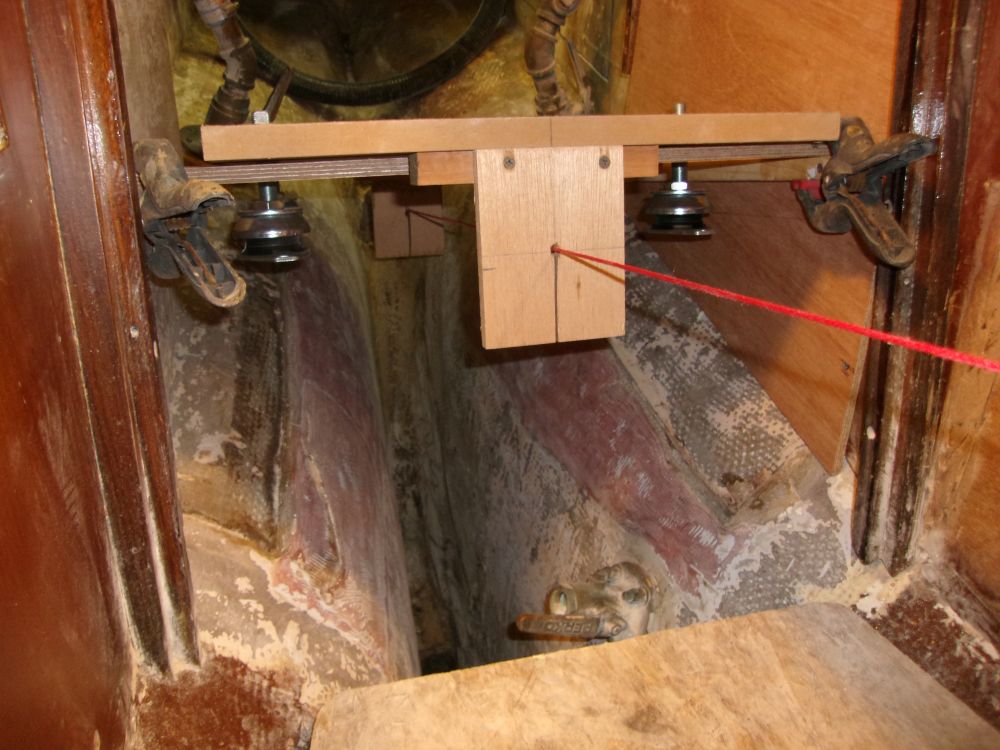
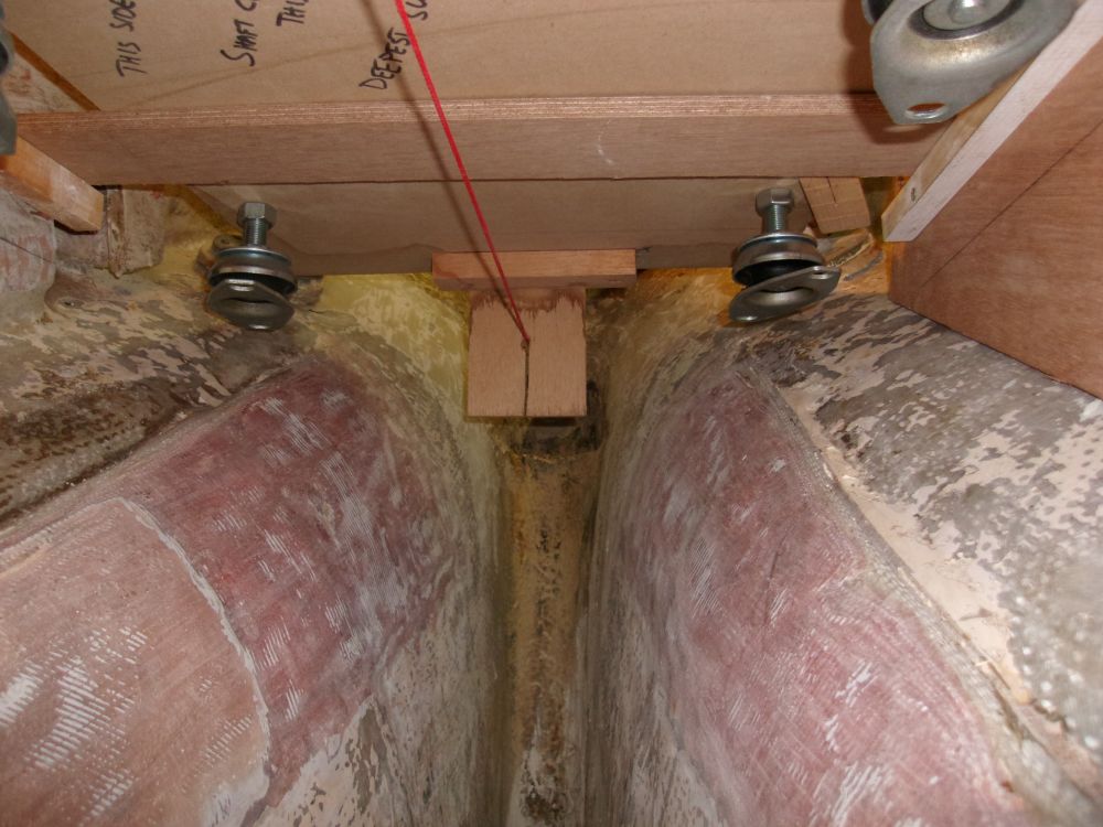
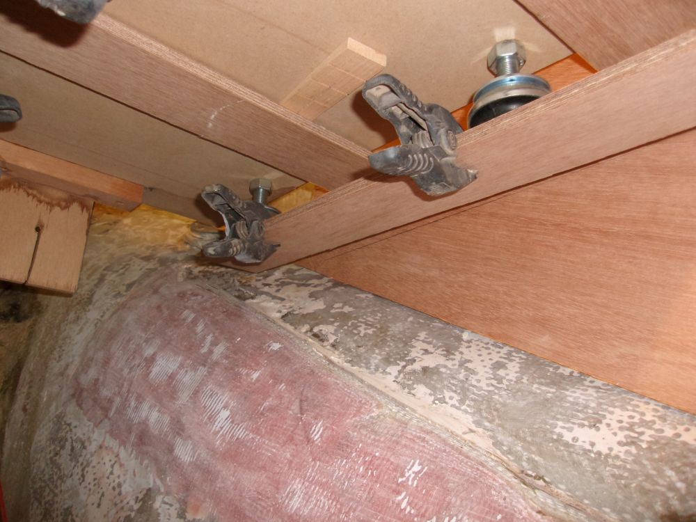
After various fussing with the template and other measurements, and eventually satisfied with its alignment and position, I prepared two lengths of 12mm (1/2") plywood, each 3" wide and 22" long, to represent the top surfaces of the eventual foundations. I clamped these to the bottoms of the flex mounts, then measured from the bottom surface of the plywood to the hull at both sides of each end, giving me the four measurements required to build and cut the foundation blanks for each side. Access to this space was tight, so once I'd clamped the plywood strips in position where I wanted them, I restrung the centering string (which I had to remove whenever possible to allow access) to double-check the template's position before making final measurements.
With the measurement I needed, I could build blanks for the foundations. I had ample 9mm marine Meranti plywood in stock, so I chose to use this even though it would require double the lamination I'd normally have to do; the foundations would eventually be 8 laminations thick, or about 3". Given this, I decided to glue up the blanks in a couple operations, rather than try to glue eight pieces together all at once.
I prepared four long strips of the plywood, each wide enough for the foundations' maximum dimension (a bit over 12"), and the full eight feet in length. After solvent-washing the bonding surfaces, I laminated the four pieces together with epoxy adhesive, driving temporary screws through to clamp the lams together, and left the initial blank to cure. Later, I'd cut it in half and glue the two halves together to make a single blank long and thick enough for both sides.
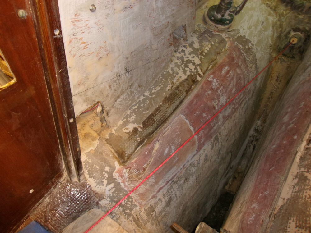
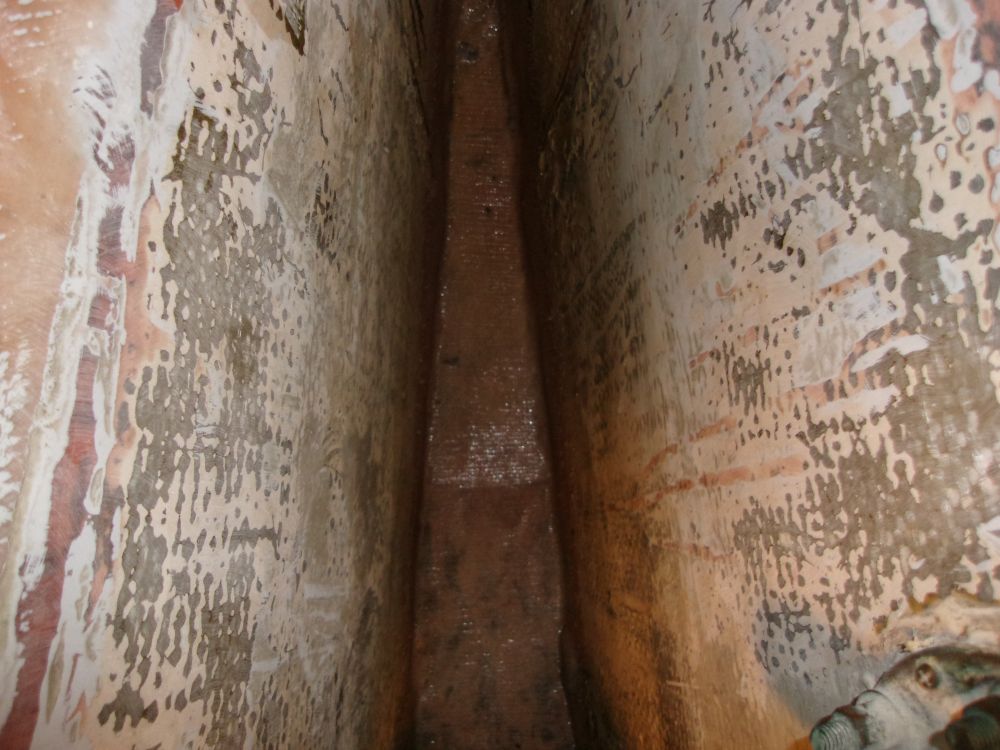
With the new foundation work and layout moving right along, it was the time to address the bottom of the bilge in the engine room, while access was still relatively good, or at least possible. The vermiculite filler in the hollow keel beneath the bilge had dried out enough on top--frankly, as much as it was ever going to without unlimited time--so I dug out enough of the filler to remove the uppermost contamination and allow room for the broken section of hard resin to fit back in.
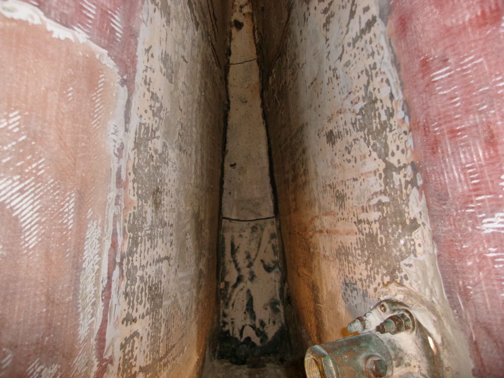
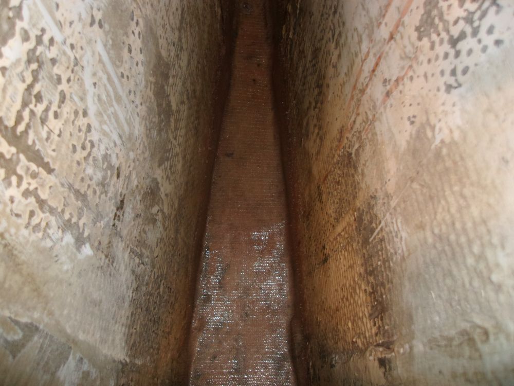
After the test-fit, I removed the piece and prepared the area with a thorough acetone wash to remove as much grease and grime as possible. It was not possible to thoroughly sand or grind this area, as tools could not fit, but earlier I'd done what I could in that regard. Preparations complete, I glued the broken section back in place with thickened epoxy resin, concentrating on providing the smoothest surface possible for transition to the sides of the keel and elsewhere.
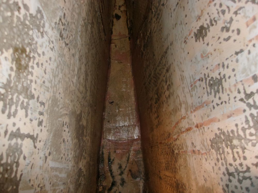
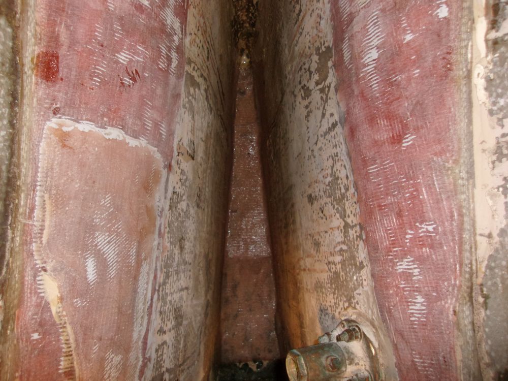
Finally, to cap and strengthen the entire area, I installed a layer of biaxial cloth that ran essentially the full length of the space, and wide enough to wrap up the sides by a few inches.
Total Time on This Job Today: 6 hours
