
110 Cookson Lane | Whitefield, ME 04353 | 207-232-7600 | tim@lackeysailing.com
Blue Teal | Wednesday, July 3, 2013
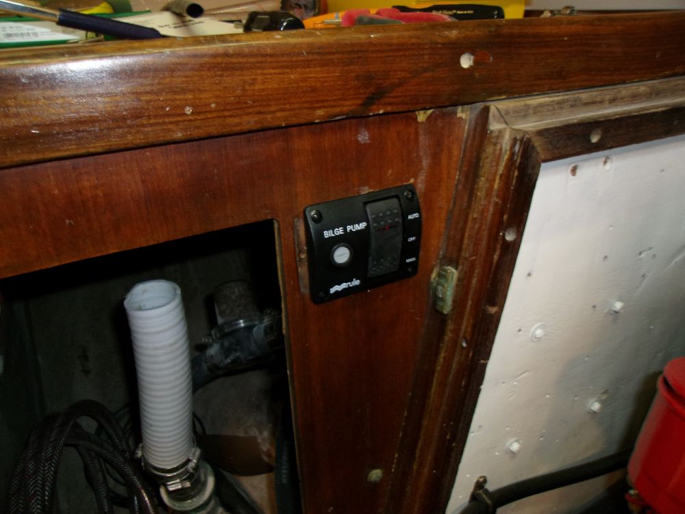
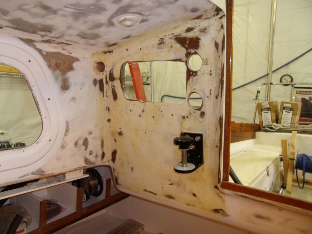
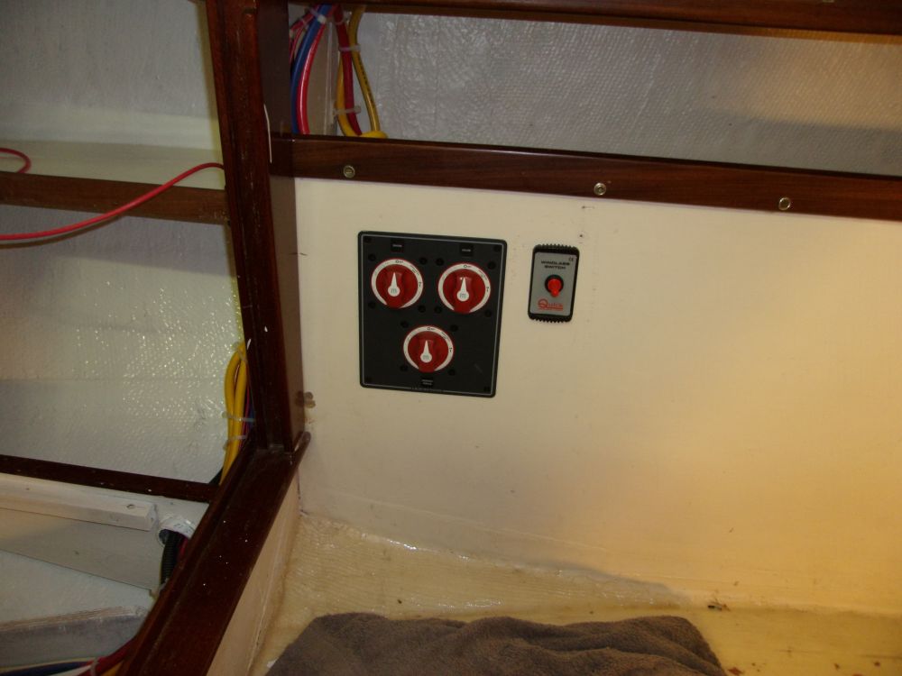
The owner had mentioned that his bilge pump switch, located near the engine box, had always been in the way of removing the ladder, so I replaced the old toggle-style switch with a less intrusive rocker-type. Of course the opening in the cabinet needed to be a little bigger to accommodate the rocker switch's body--just the switch part, not the whole unit. It wasn't a lot, but just enough to turn a 5-minute job into a 30-minute one.
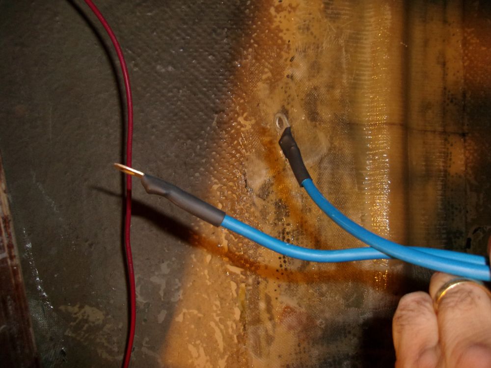
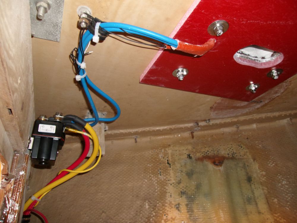
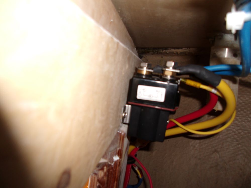
With the correct terminal ends now on hand, I made up the terminals on the windlass's wire ends, then connected them to the contactor as required, securing the wires out of the way to the overhead. The two small wires coming from the windlass were not used in this installation.
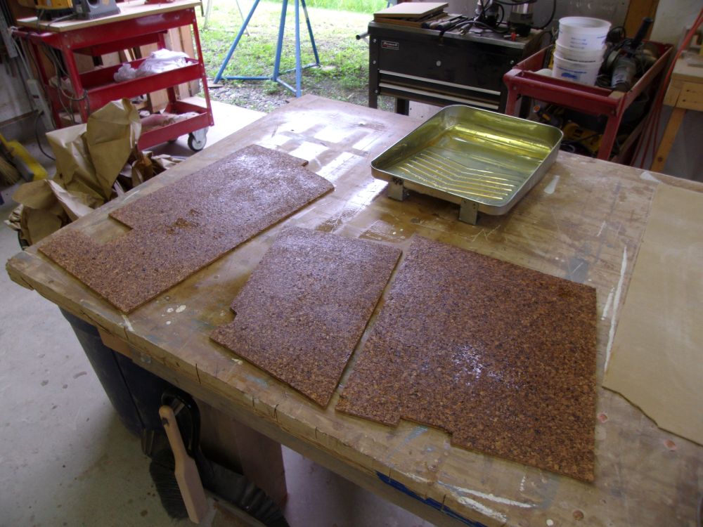
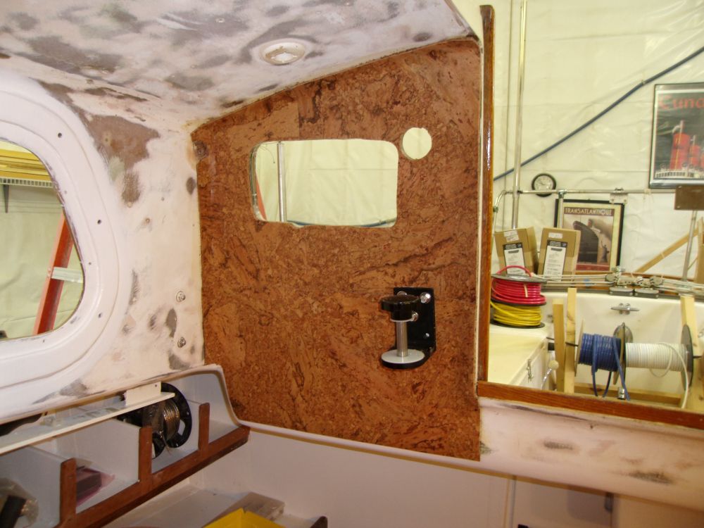
After a couple days of testing solvent-based adhesives on the cork tiles with no signs of negative results, we decided to attempt a small installation on the boat using normal solvent-based contact adhesive. This would accomplish two things: first, to see how well this product worked to secure the tiles to the boat; second, since I planned to leave the test pieces alone for a bit of time before proceeding with more installations, we could determine whether any ill effects occurred over time before committing to the whole job.
Using the three sections of cork from the failed installation attempt, I cut three new pieces, since the old ones were contaminated with the failed adhesive. Then, I applied contact cement to the bulkhead and backs of the tiles, applying two coats to the tiles because of their porous nature.
Once the adhesive dried, I pressed the tiles into place, carefully aligning them and pressing them into the various contours and curves before rolling them out with a J-roller. The adhesive seemed to work extremely well, holding the cork securely even in some of the challenging compound curves of this space.
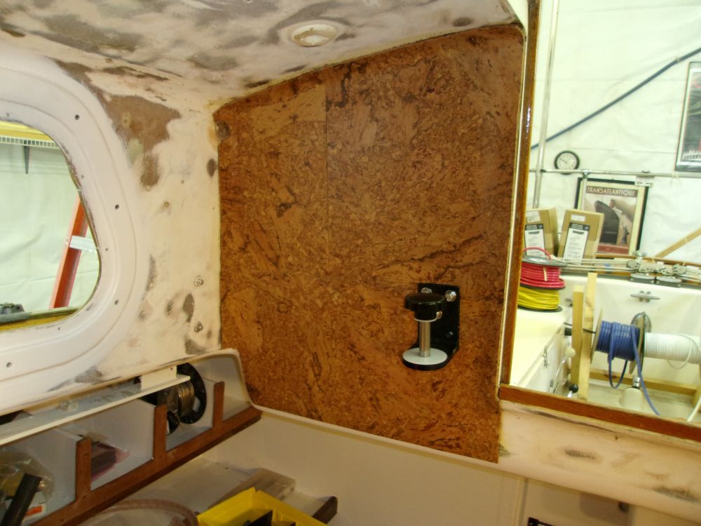
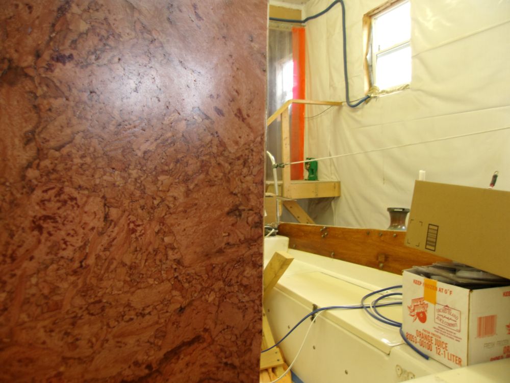
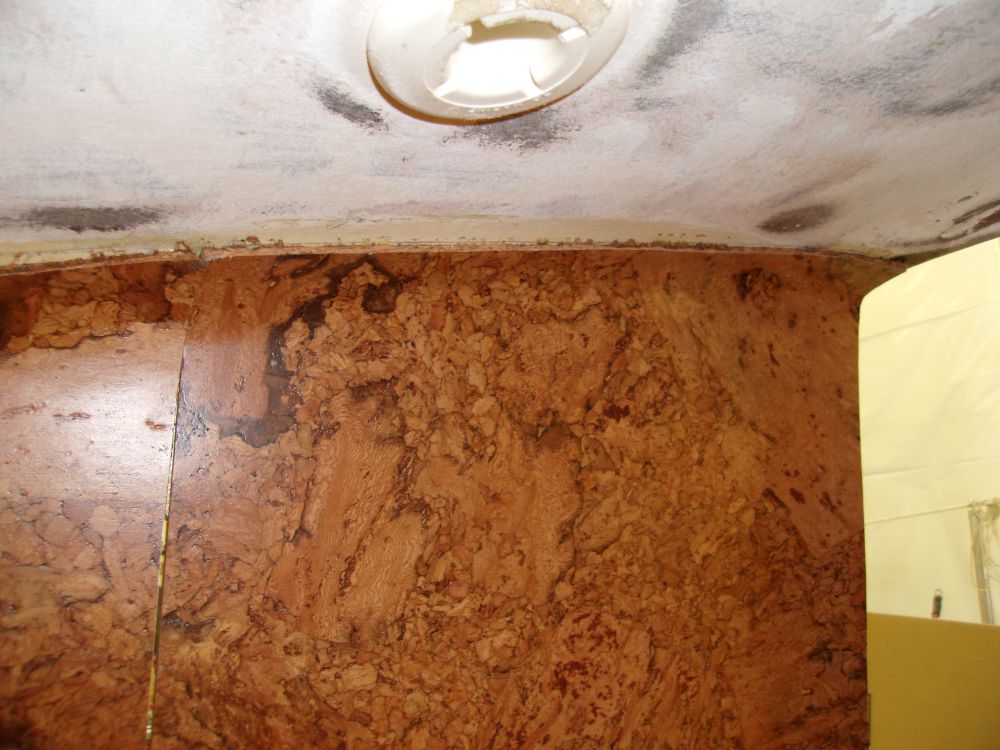
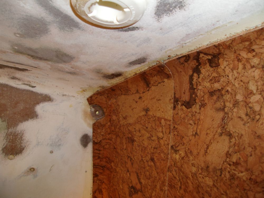
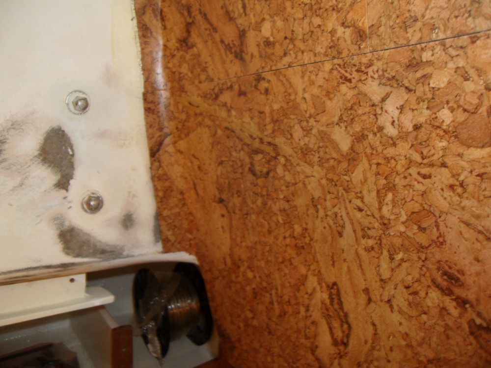
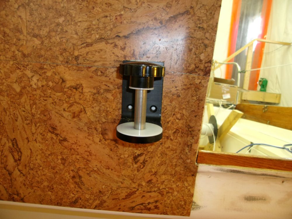

Afterwards, I used a sharp knife to cut out the large opening for the engine panel, plus the adjacent round hole for the windlass switch. Initial results were encouraging, but we'd see if anything happened in the coming days.
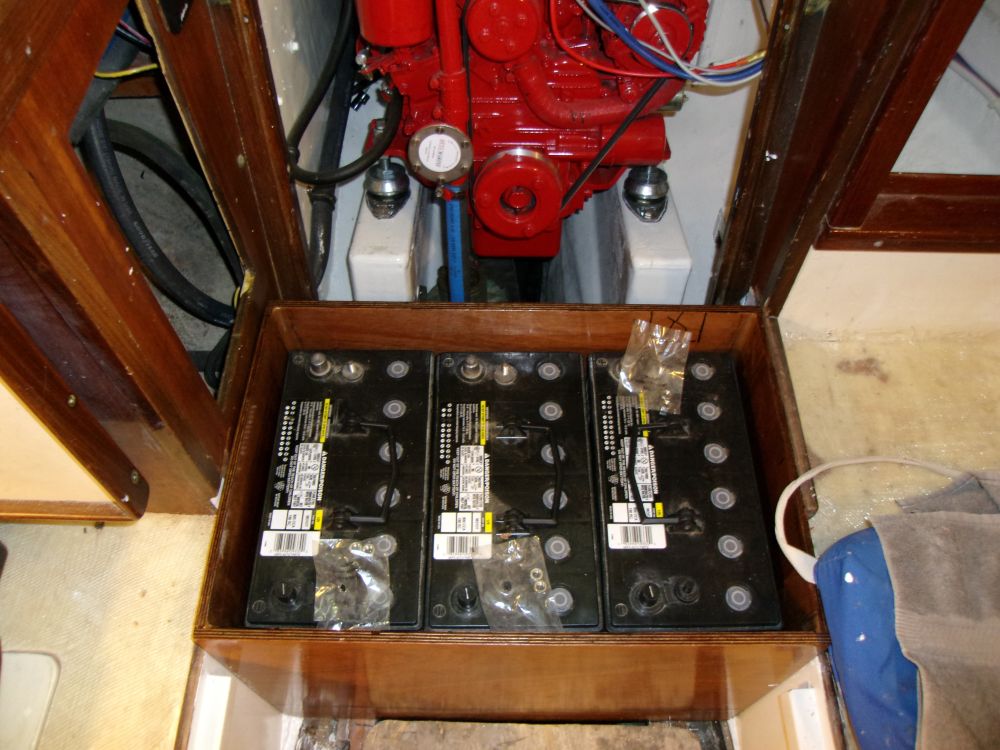
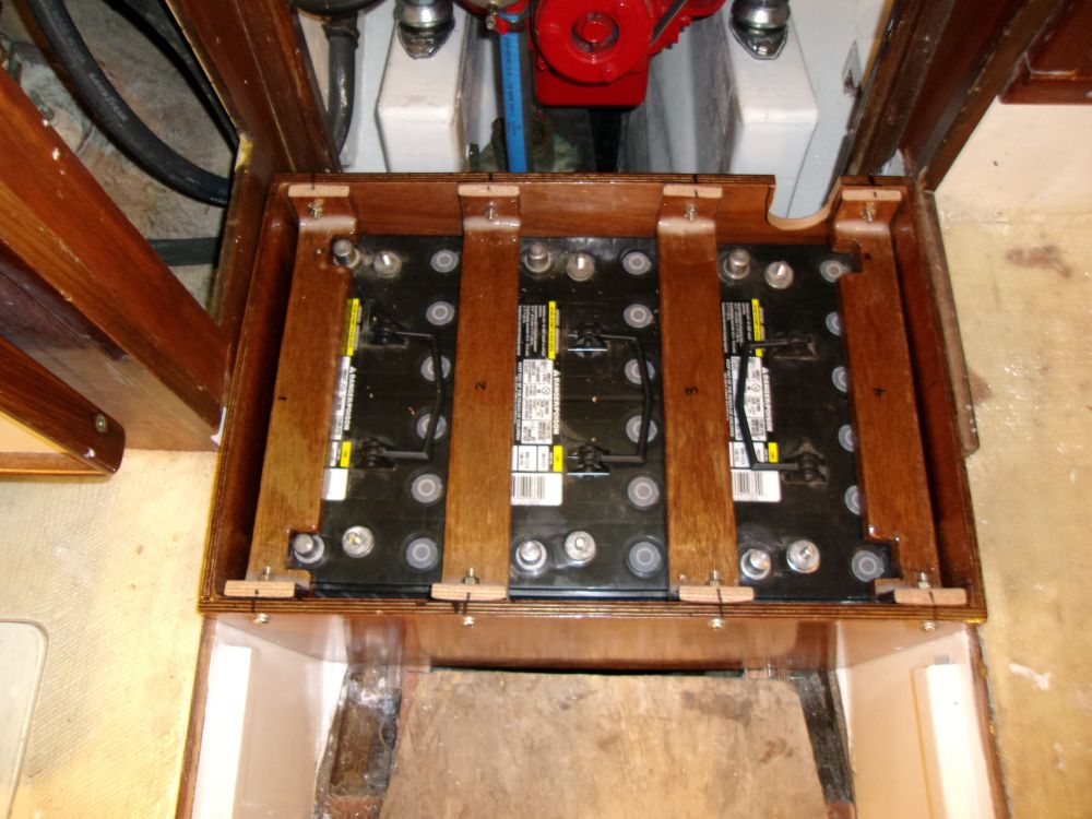
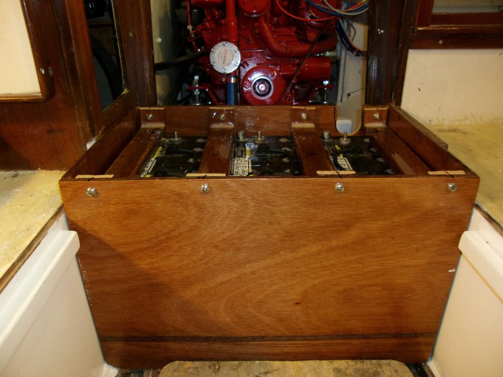
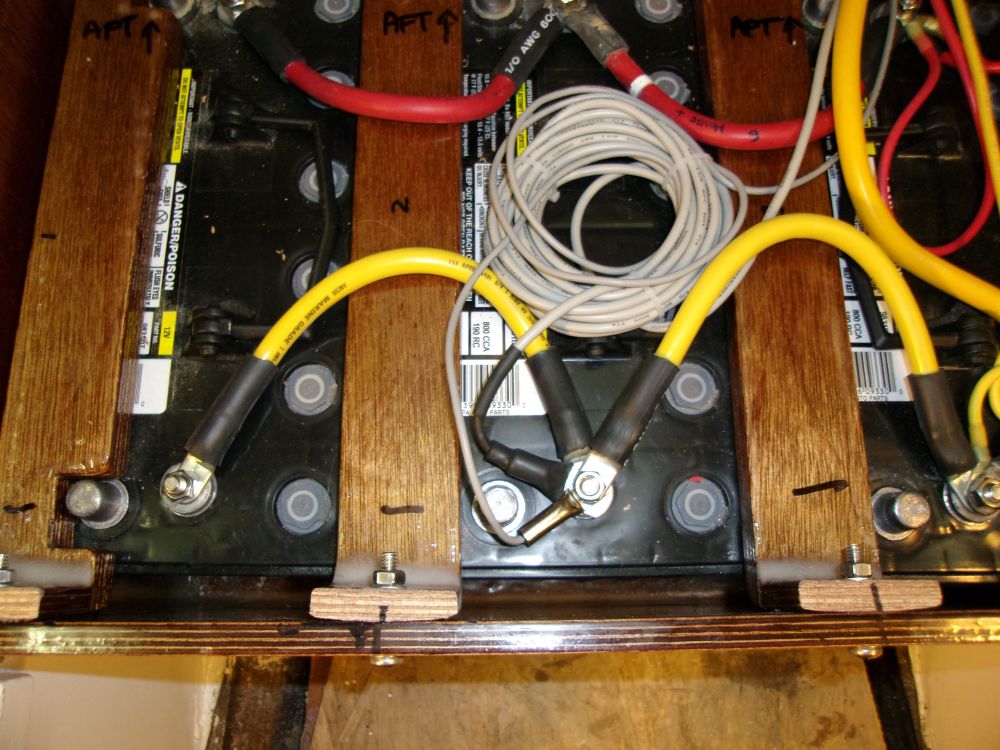
Next, I lugged the three house batteries into the boat (group 31 AGM) and placed them in the battery box. Using epoxied plywood hold-downs provided by the owner, I secured the batteries in the box with bolts, after cutting the excess lengths off the hold-downs to remain flush beneath the top of the box. Meanwhile, I cut an opening in the aft side of the box for the battery cables and wiring.
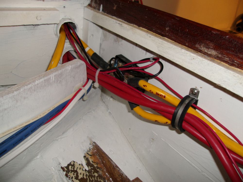
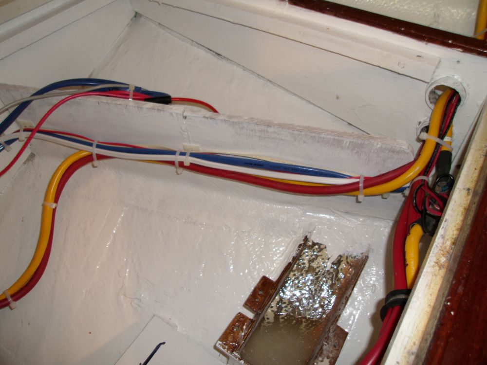
During the remainder of the day, I worked on the battery cabling for both battery banks--house and starting. The essential cable runs were a bit simpler than the old system, which had included a battery combiner and starting relay (which required several additional cable runs) and I reused lengths of the old cables (installed in 2008) for the new cable runs and jumpers, cutting them to their new lengths as required. For the house battery bank, I installed jumpers to connect the batteries in parallel, and ran in the temperature sensors for the alternator regulator and solar charger, plus the wire pair leading to the solar charger, along with the input lead for the Duo Charge starting battery charger.
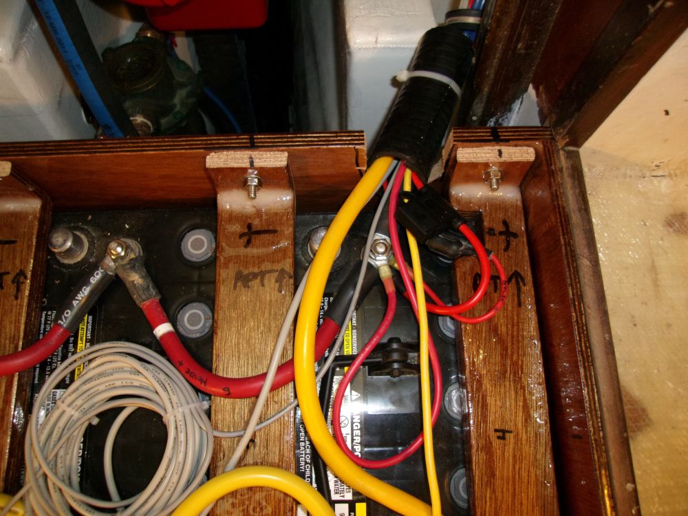

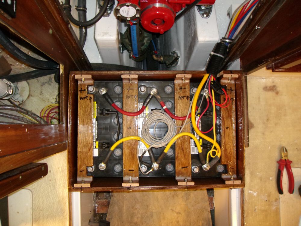
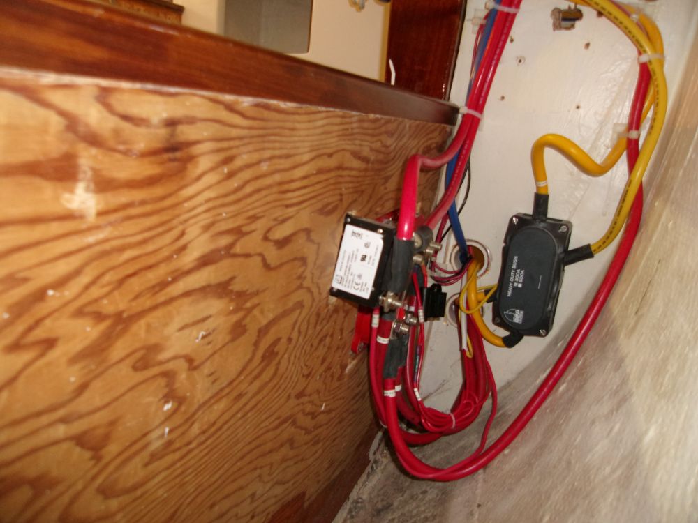
The main positive battery cable led to the back side of a battery control panel located in a nearby cabinet; the negative wire led by way of a shunt (for the battery gauges) to the main negative distribution buss located behind the battery panel. I also added an always-hot wire to the battery switch, which I led to a nearby cabinet where I'd presently install a dedicated buss for things like the electric bilge pump. In addition, I led power wires from the Duo Charge and regulator to the starting battery switch, so these components would be powered on whenever the start batteries were enabled.
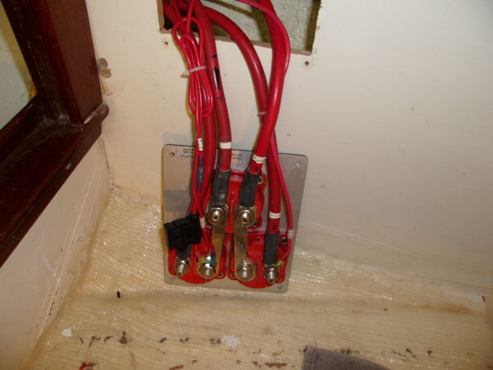
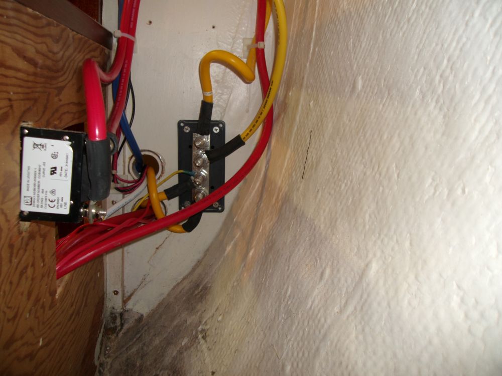
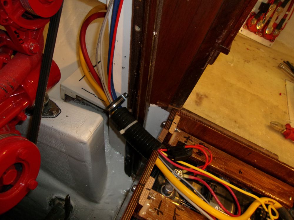
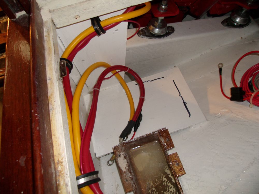
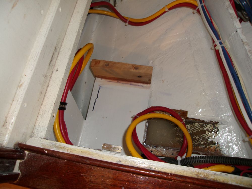
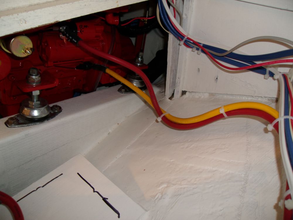
Meanwhile, I prepared lengths of cable for the start battery, leading from the shunt/negative distribution and start battery switch to the new starting battery location adjacent to the engine. Before installing the battery, I epoxied a sturdy cleat at the aft end of the platform which, along with a strap, would hold the battery in position.
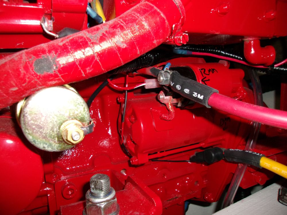
From the appropriate terminals on the negative distribution buss and start battery switch, I led the permanent cables to the engine ground and starter.
Total Time on This Job Today: 7.5 hours
