
110 Cookson Lane | Whitefield, ME 04353 | 207-232-7600 | tim@lackeysailing.com
Blue Teal | Monday, July 1, 2013
Some days, everything rolls along swimmingly. This was not one of those days.
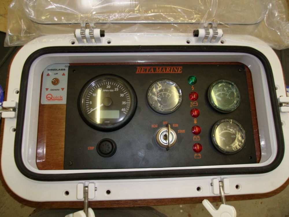
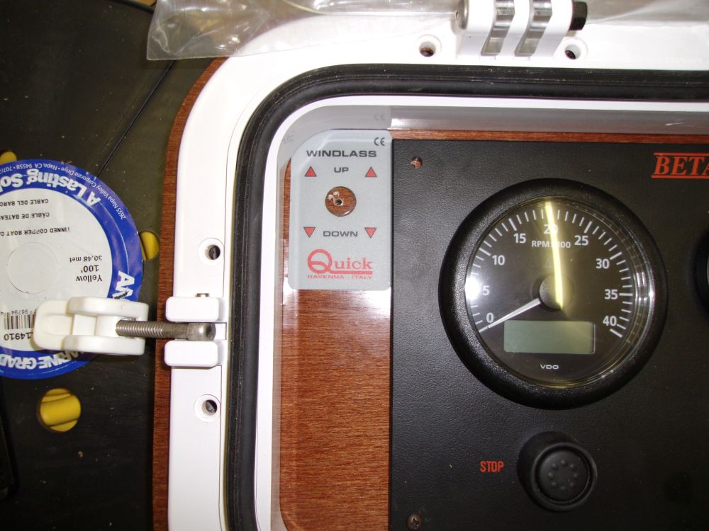
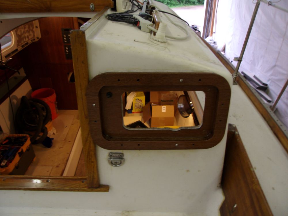
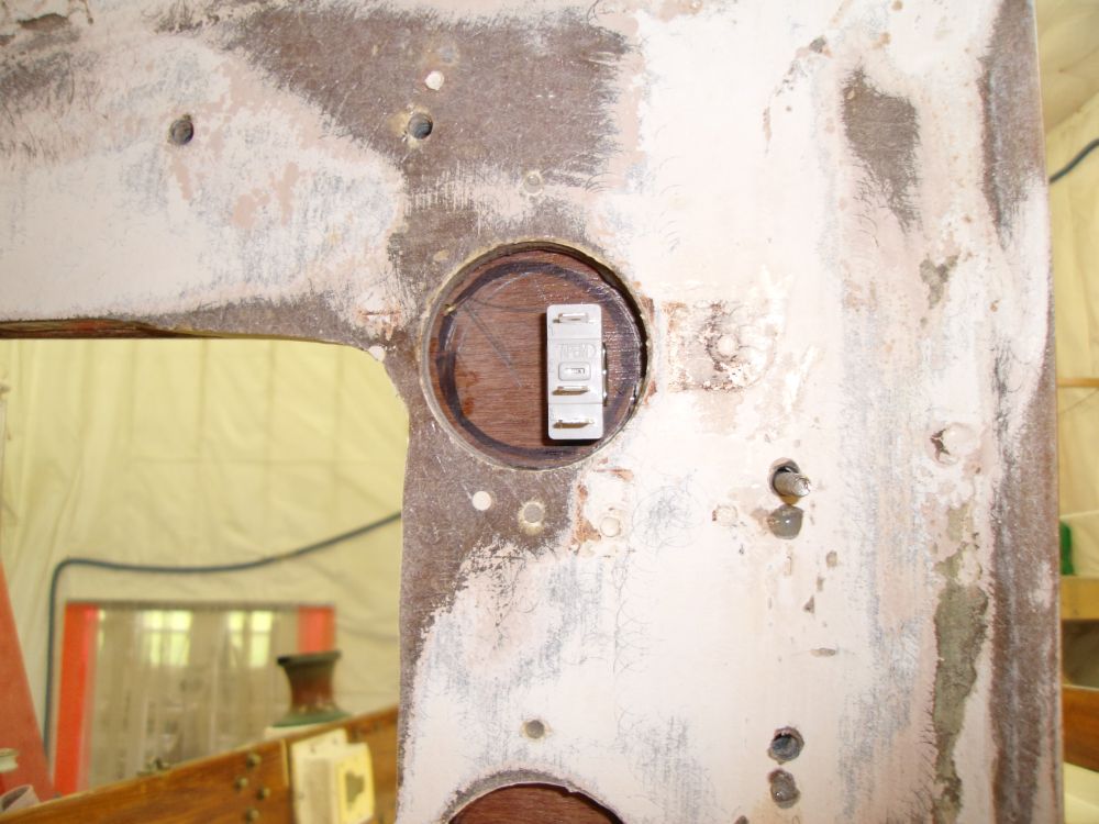
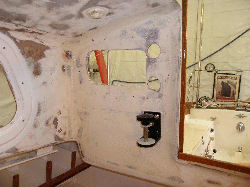
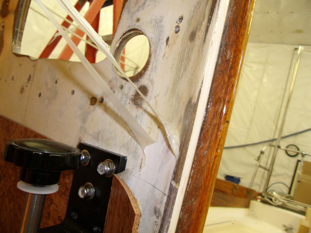
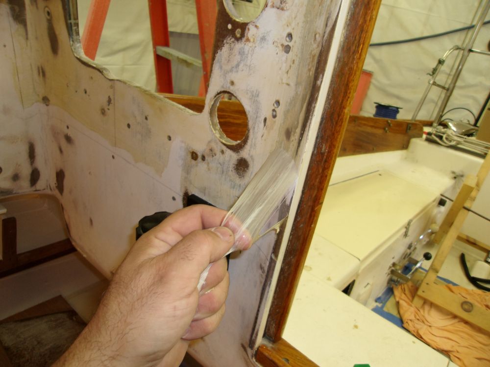
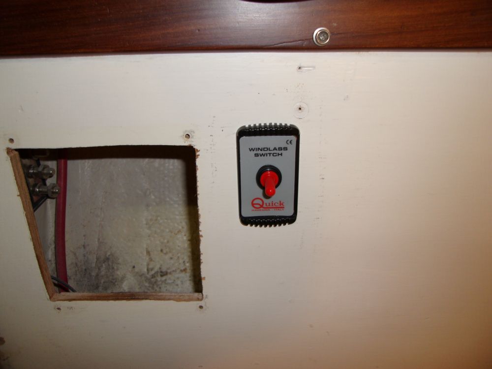
I planned to turn my focus to some of the wiring work. First, however, I wanted to take some steps to prepare to install a wooden surround and plastic cover for the engine panel, located on the starboard aft cabin bulkhead facing the cockpit. Since this location would require wiring along this bulkhead, I hoped to install the surround sooner than later, but first I needed to locate a windlass control switch in the panel.
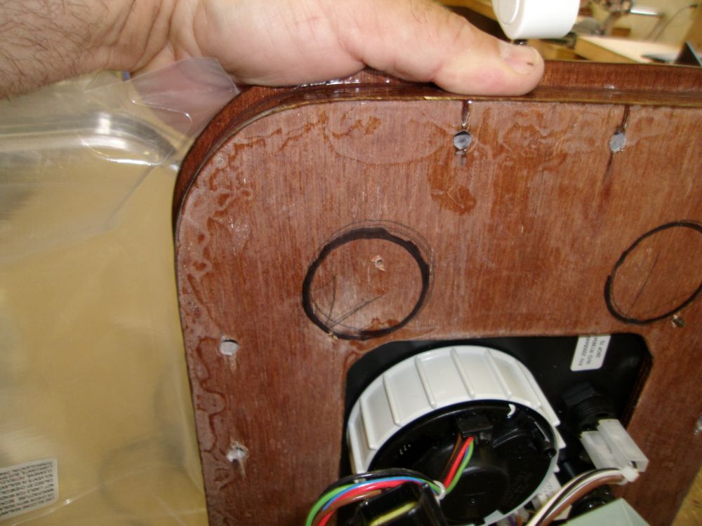
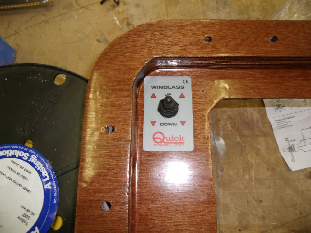
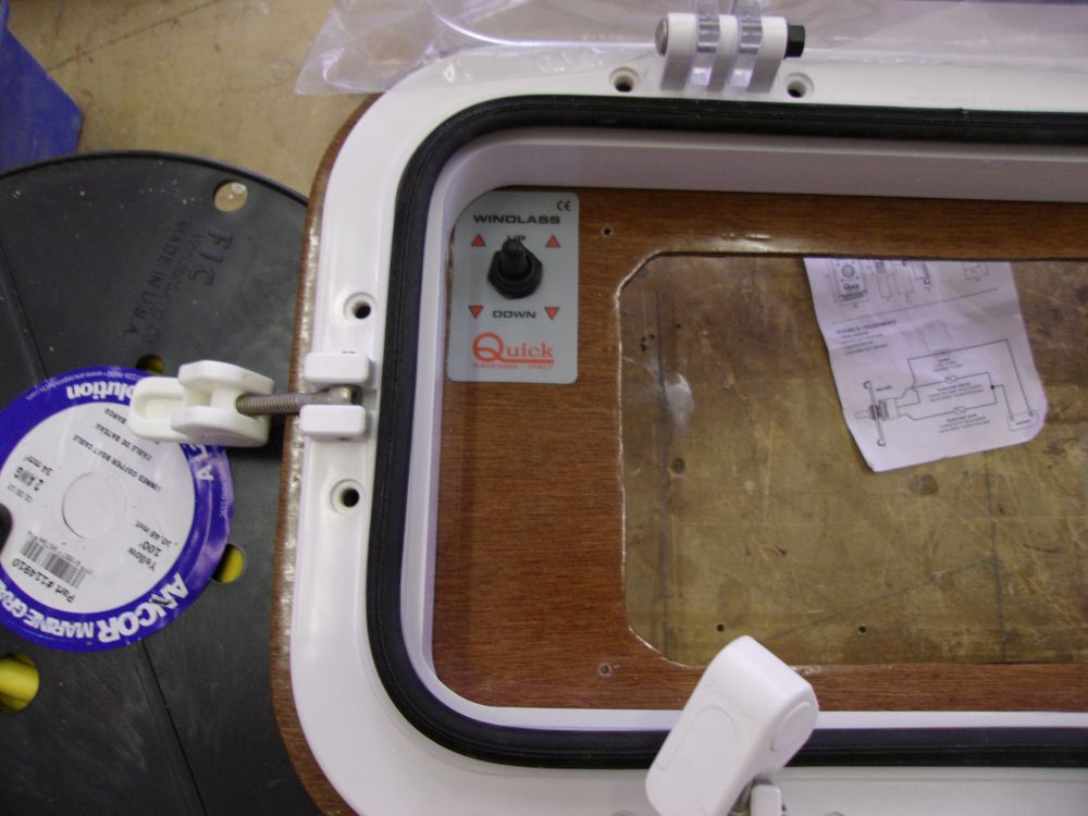
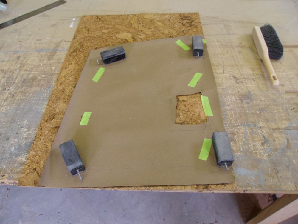
Since the switch body wasn't long enough to extend through the thickness of the cabin trunk, much less with the surround attached, I hoped to mount it in way of two existing holes in the bulkhead, so that the switch would have to extend only through the 1/4" thick surface of the plywood surround. However, the placement of the engine panel and space limitations didn't make this easy. With the surround temporarily pinned in place, I marked the locations of these circular openings from the back side, then, back on the bench, worked out the single location that would work for the switch while still allowing its cover plate--or at least the adhesive portion of the cove plate, as I found I had to leave off the plastic cover plate since the curvature of the surround, coupled with the required position of the switch (in order to allow it clearance from behind) didn't allow room for the plastic cover.
As it was, I could just position the switch within the existing hole in the bulkhead, so the project was ultimately a success.
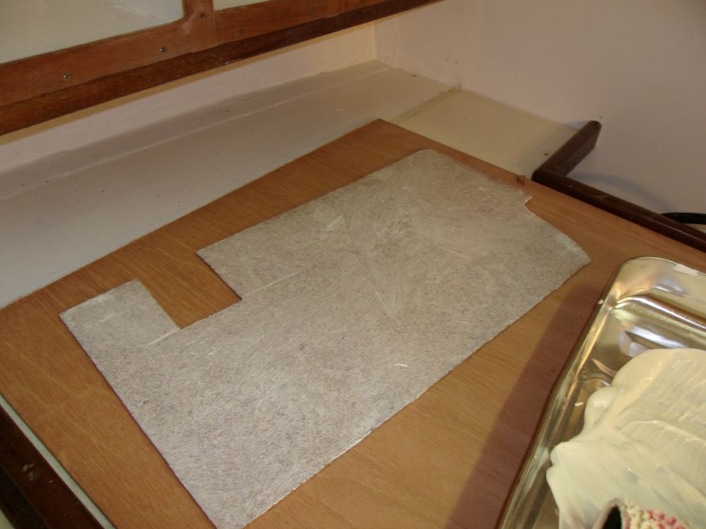
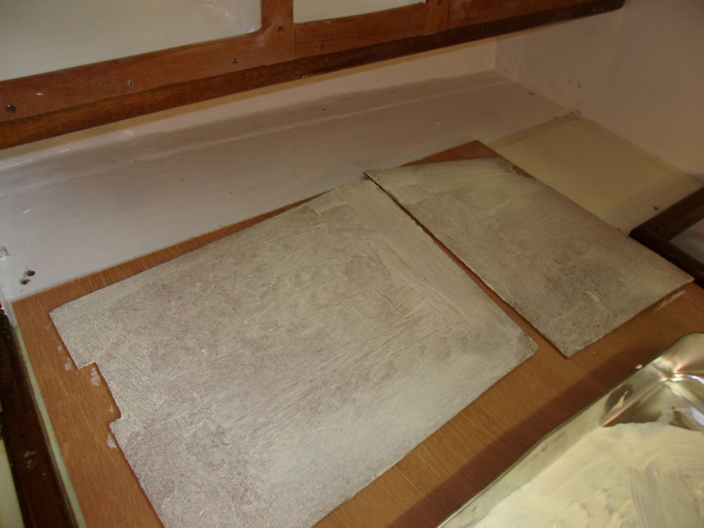
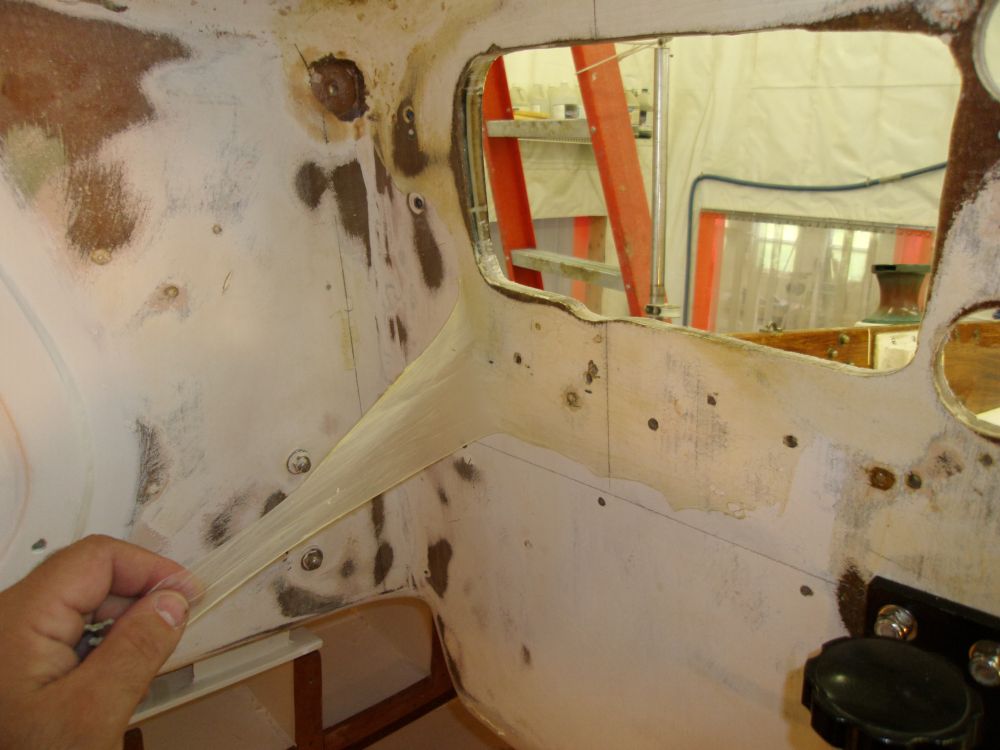
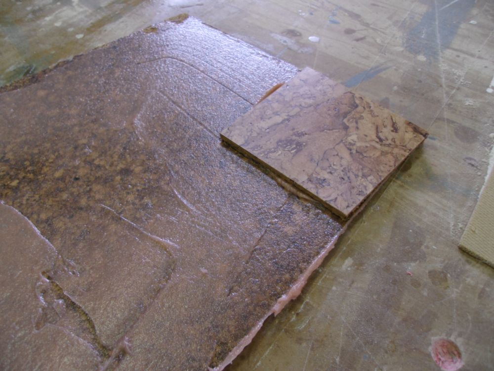
Before I could install the panel and surround, I wanted to install the cork on this bulkhead. So next, I prepared a template of the space, then cut three sections of cork tiles to fit. It wasn't the easiest section of the boat to begin with, but the way the cork seemed to effectively bend around the corners gave me encouragement.
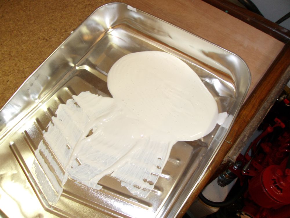
The manufacturer required use of a special latex-based acrylic contact adhesive that was compatible with the water-based binders in the cork tiles themselves; I applied the adhesive to the back side of the cork tiles and to the bulkhead as directed, then let it dry.
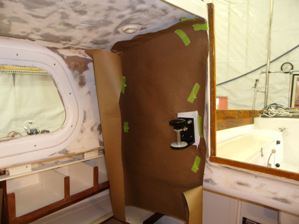
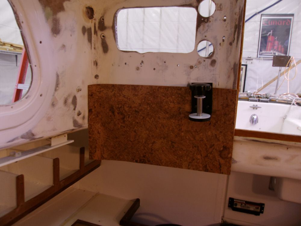
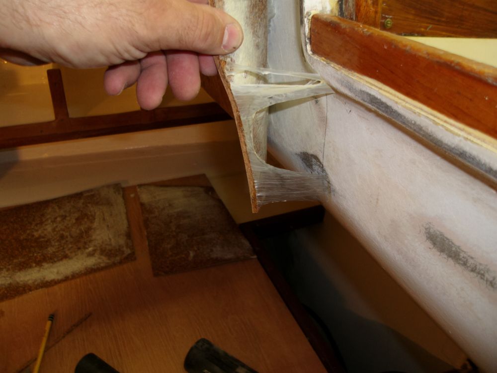
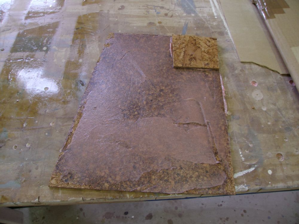
Then, I pressed the first piece of cork into place. Immediately I noticed issues: at a couple of the edges, the cork wasn't adhering, and at first I feared that despite its relative conformity to the curvature, the adhesive wouldn't be enough to hold the cork into position. However, I soon discovered that this wasn't the issue. The issue was that the adhesive had not bonded to the substrate whatsoever, so the cork was simply bonding to the adhesive and pulling it away from the bulkhead.
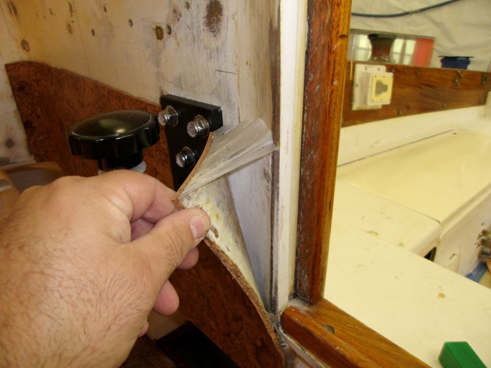
After various attempts to troubleshoot or salvage the situation, I realized the utter futility of it all, as the adhesive simply was not going to work, so I removed the cork and, rubbing my hands over the surface, easily removed all the cured adhesive from the bulkhead, like so much rubber cement. Latex had no place on a boat anyway.
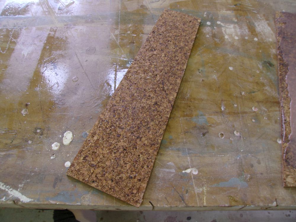
Later, despite admonitions on the manufacturer's website, I applied some regular solvent-based contact cement and thickened epoxy to some scraps of cork to see how the product reacted. Information on the website suggested that solvent-based products would cause either Armageddon or the dissolution of the binders in the cork tile--I forget which, but in any event neither happened during the several hours after my applications, but we'd see what happened later and do some more testing before considering proceeding in this direction.
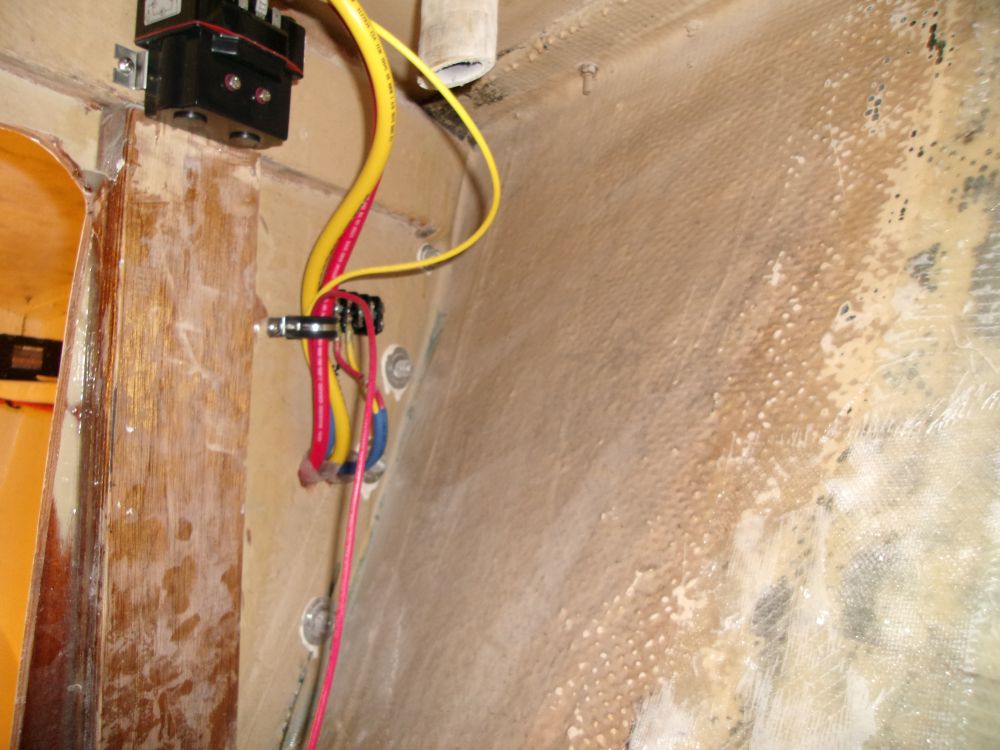
The cockpit-mounted switch for the windlass was for basic up/down operation from the remote location, one of two controls planned for this boat (the other being a wired remote control for the foredeck). In addition, there was a main circuit breaker for the system, which, during a previous meeting, the owner and I had decided to install near the main battery panel on the port side. So I installed the breaker here, a relatively simple process made more time consuming by the need to slot the plywood to accommodate the entire size of the breaker, again because the switch body was not long enough to thread through anything much more than a thin metal panel. So after several additional installation steps, I got the breaker installed as required.
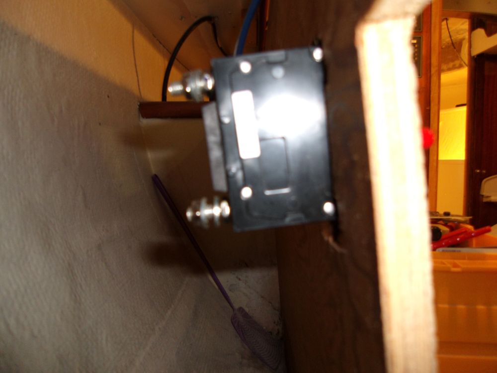
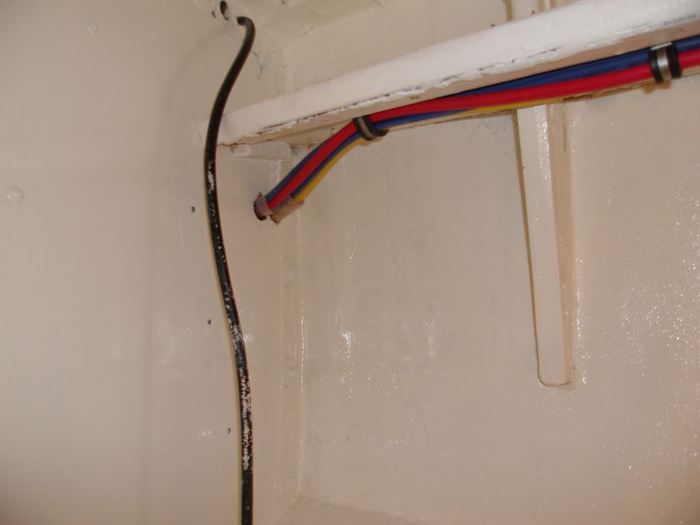
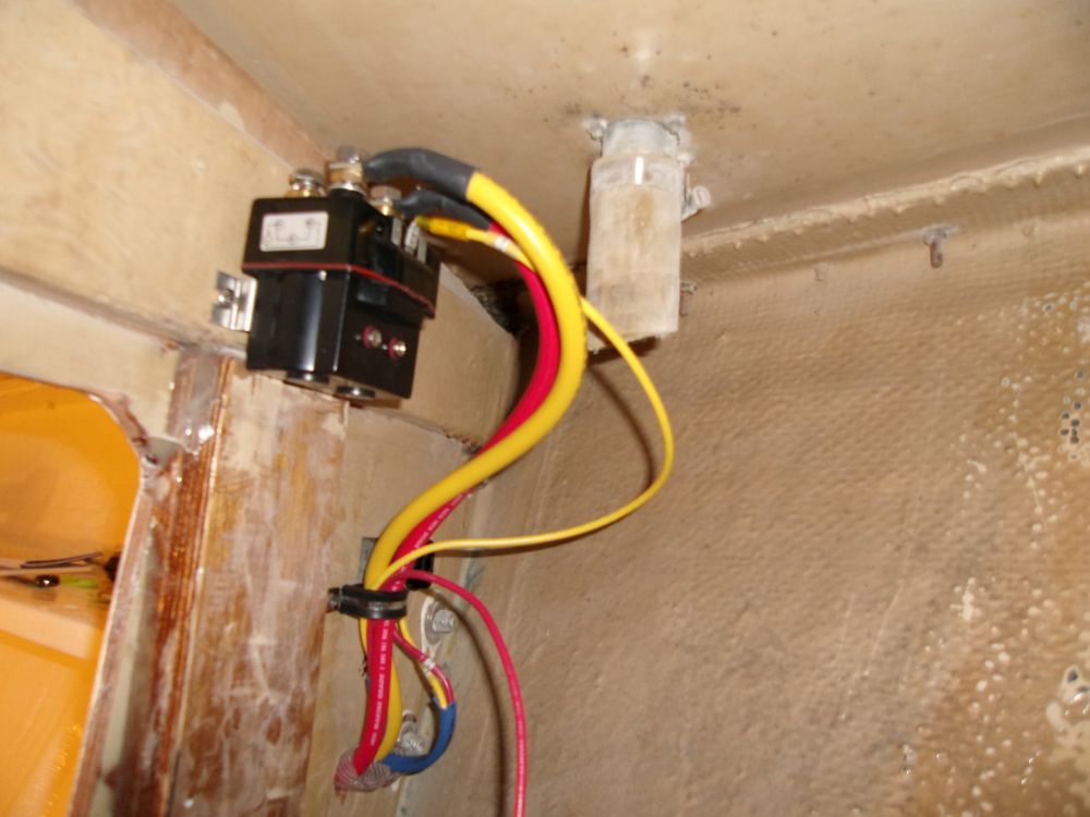
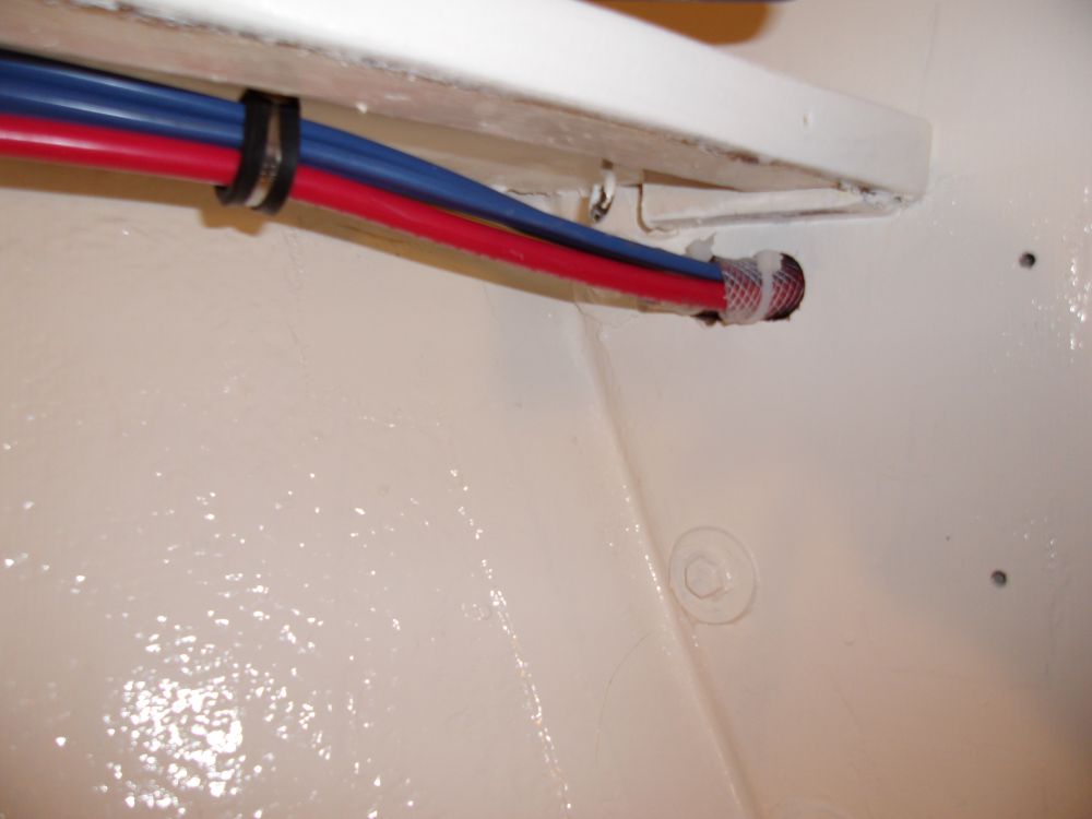
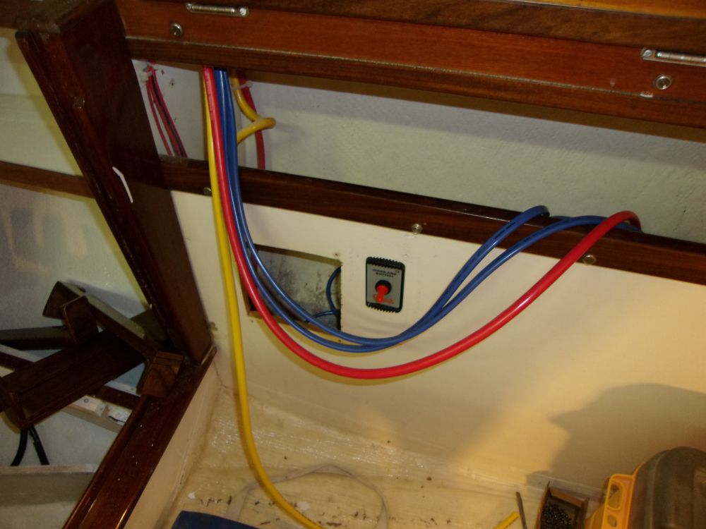
Next, I installed the contactor control box for the windlass up in the corner of the chainlocker. I found I didn't have the correct terminal ends to fit the wires leading from the windlass itself, so I left those for later, but I ran the two lengths of #2 battery cable forward to the space from the aft part of the cabin, leading the cables forward through lockers and beneath the shelf in the forward cabin. I made up the terminal ends at the forward side, and connected these wires to the contactor.
The system also required four additional smaller wires to interconnect the two separate control units with the contactor and 12-volt power source, so I led two pair of sheathed wires forward for these tasks; I installed a terminal block near the contactor to ease interconnection of these wires later, as I'd not be installing the wiring for the foredeck remote control just yet.
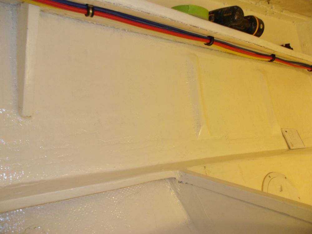
Afterwards, I secured the windlass wiring along its route through the cabinets and along the port V-berth shelf, leaving the after ends unsecured for now pending their final connections to the circuit breaker and power source as required.
Total Time on This Job Today: 8.25 hours
