

April 7, 2025
Miss Helen 16
Monday
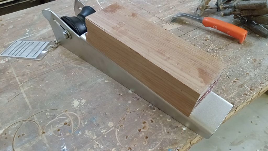
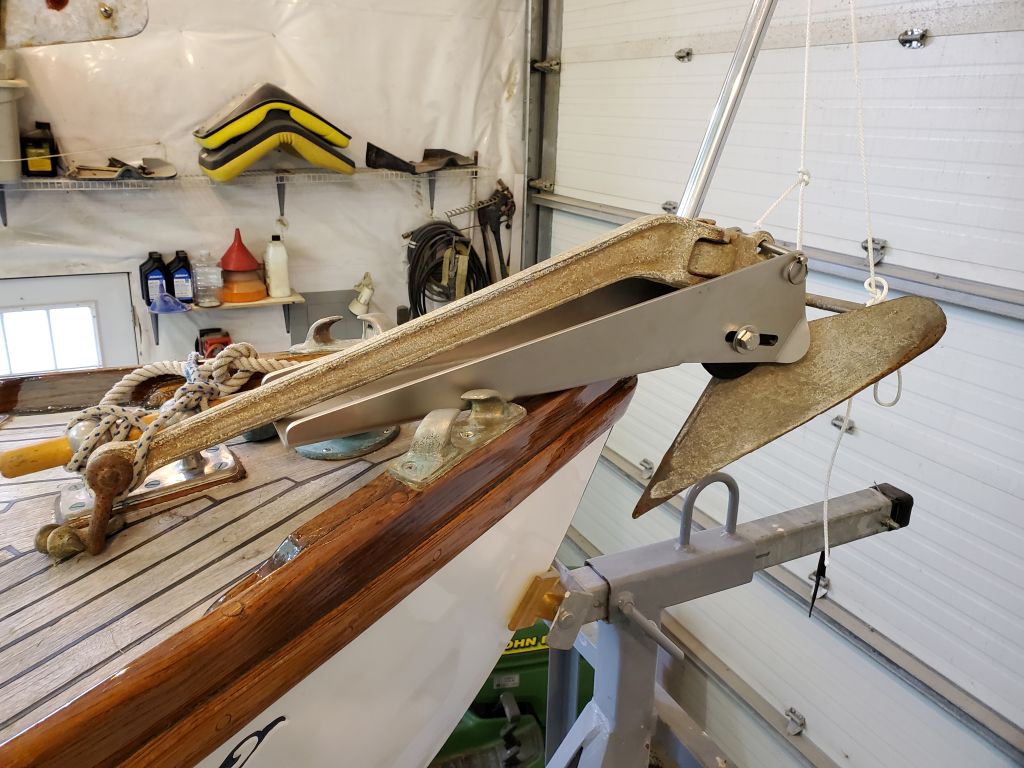
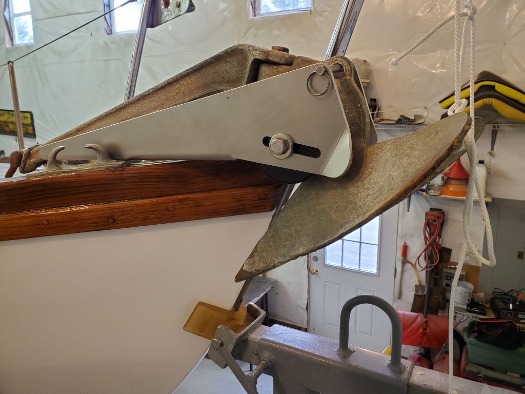
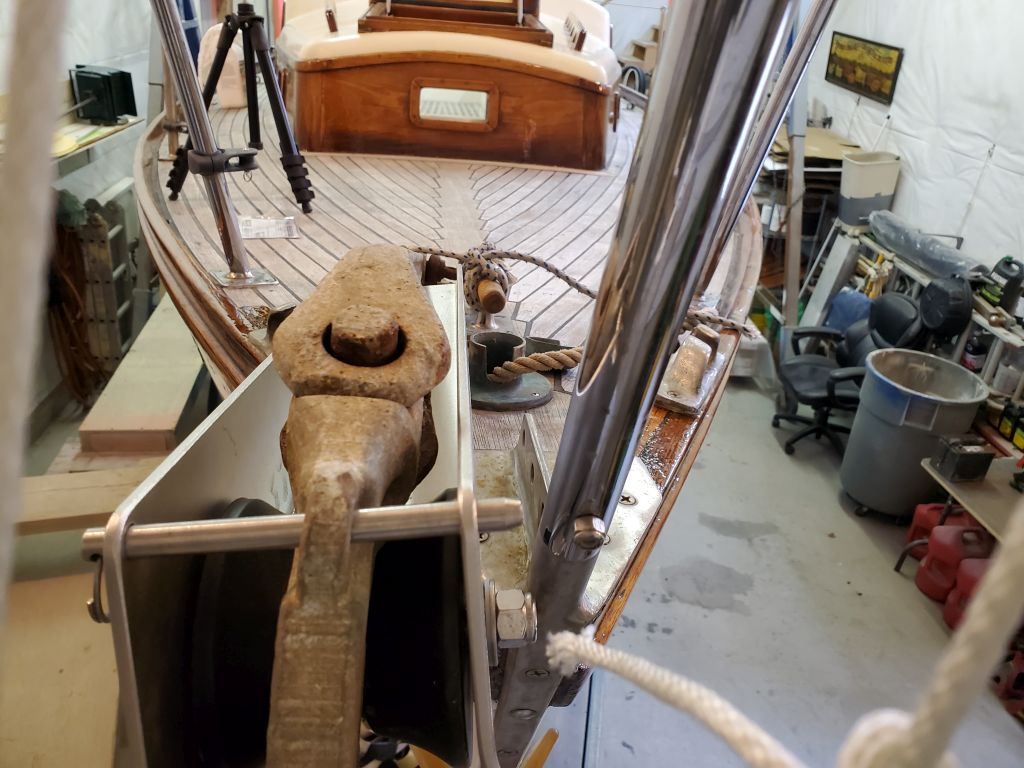
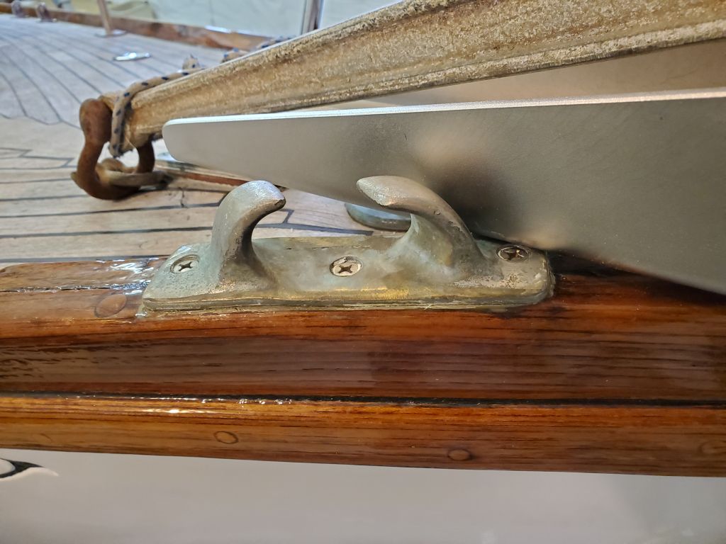
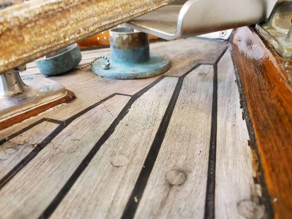
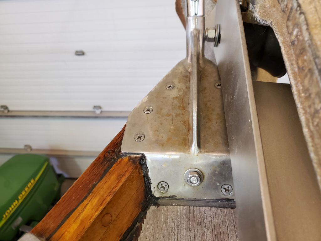
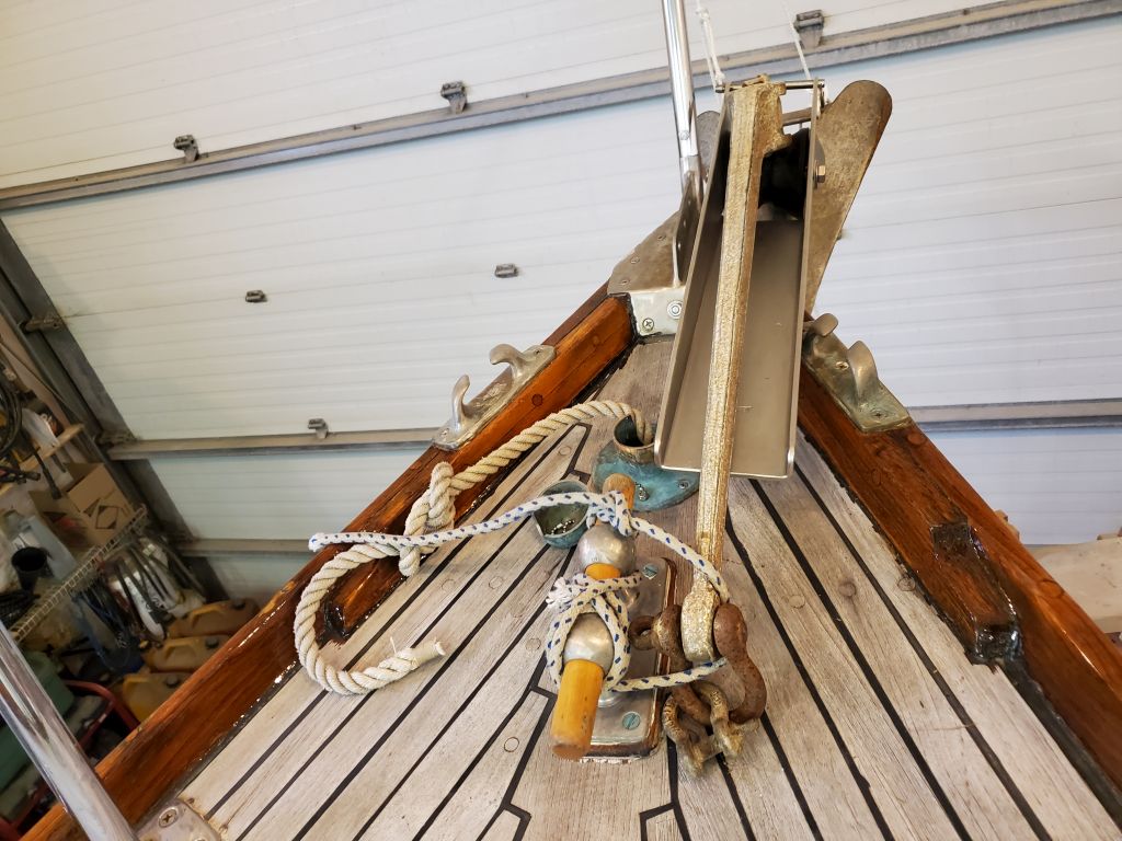
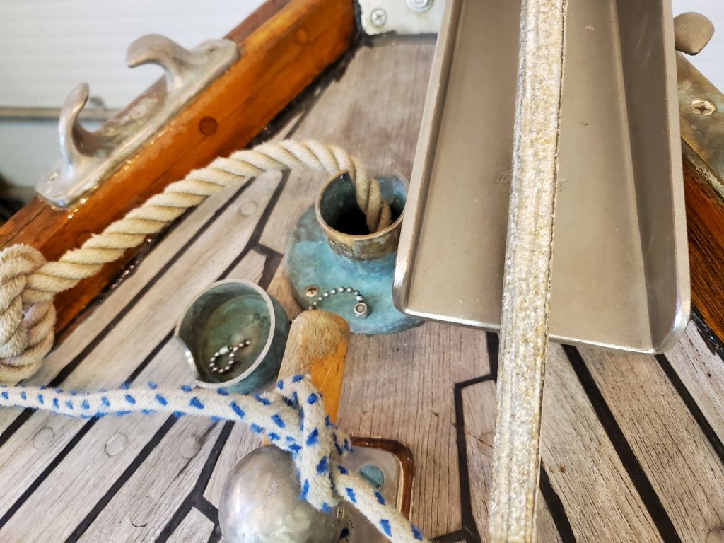
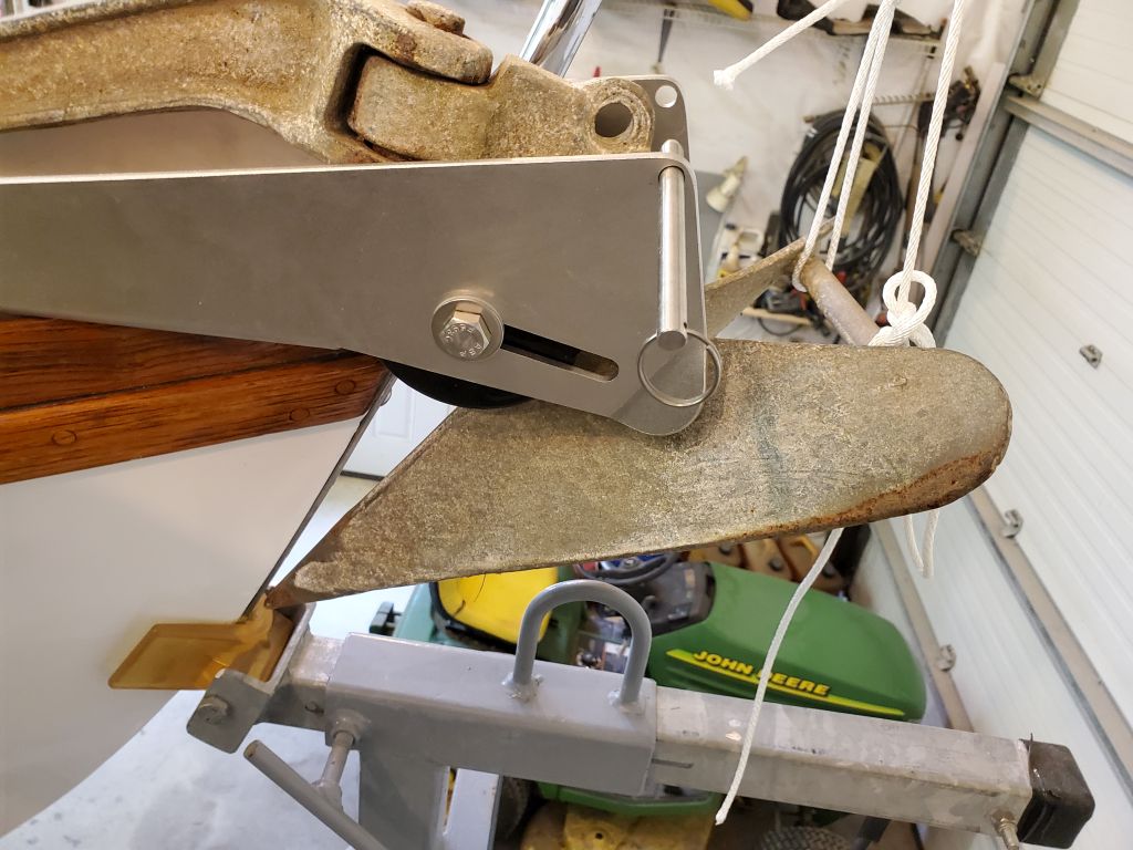
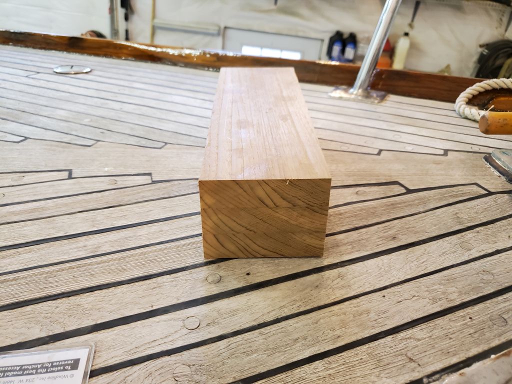
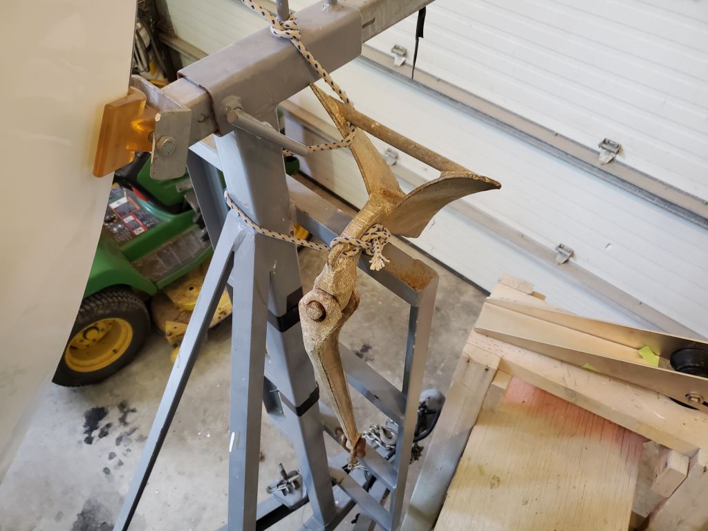
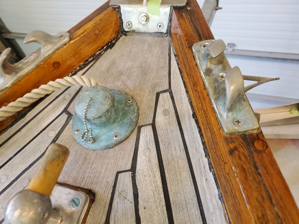
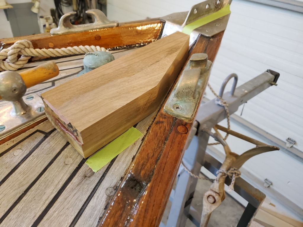
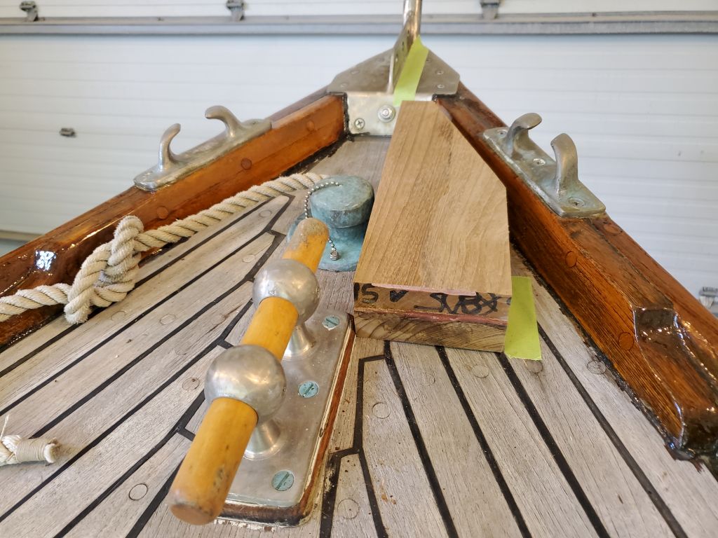
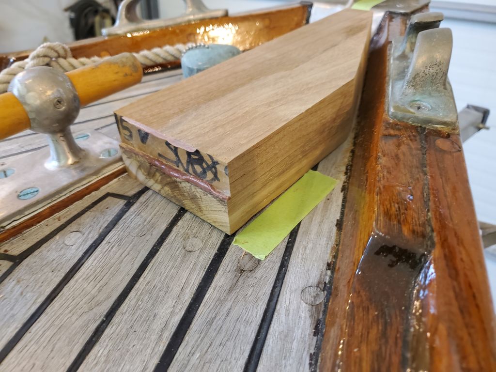
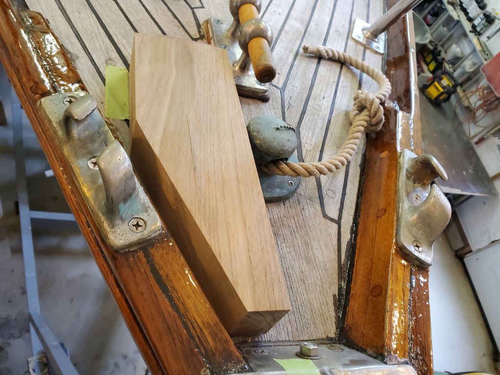
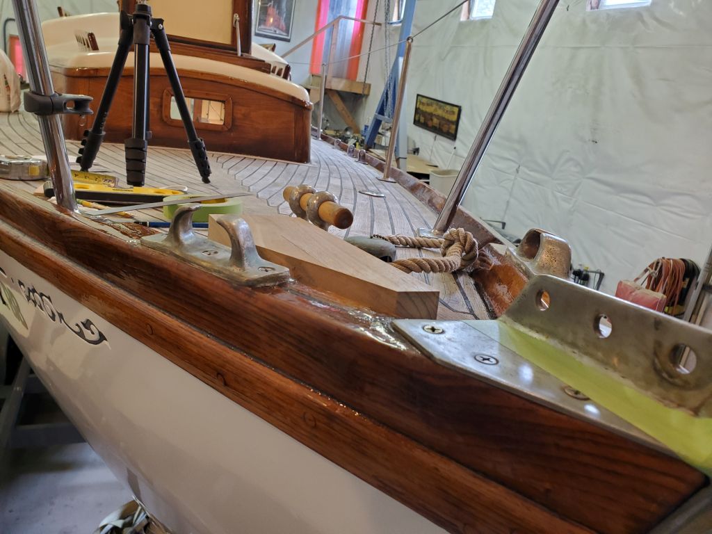
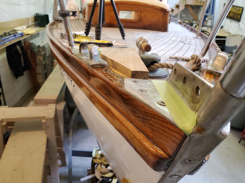
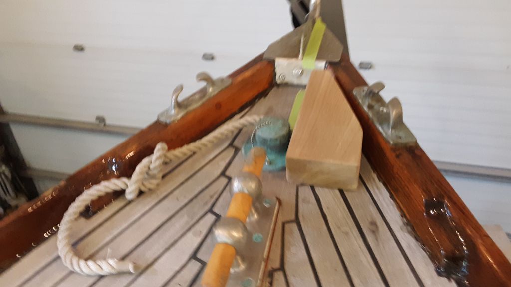
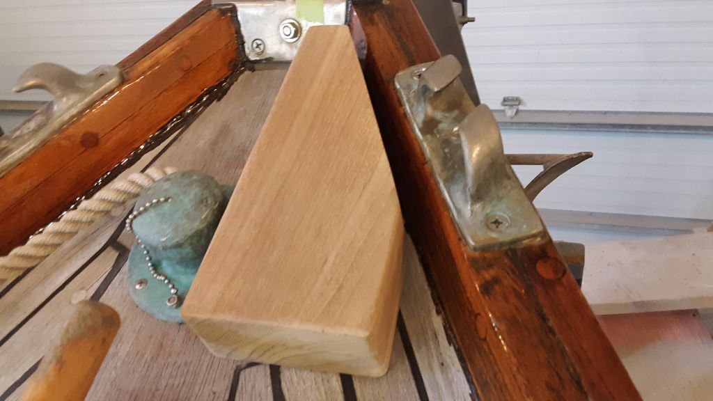
Temporarily installing the anchor–a 25#CQR from my used anchor graveyard–in the roller, I spent some time mocking up the roller position (and by roller I am referring to the entire assembly) on the starboard side of the stem. It was a tight space, and there were various impediments, among them the centerline pulpit support, stem plate (where the headstay and jib tack would install), starboard bow chock, hawsepipe, and bow cleat (both located on the centerline a bit aft of the stem proper). Cutting the toerail and extending the roller through at deck level wasn’t an option because of the design of the stem plate, and other considerations, though I wouldn’t undertake such a “permanent deformity” lightly in any case, so the roller would extend over the level of the toerail. To this end I’d previously glued up a teak spacer block that I’d soon use to fit between the roller and the deck, and at the beginning of the day I’d unclamped and dimensioned the blank roughly.
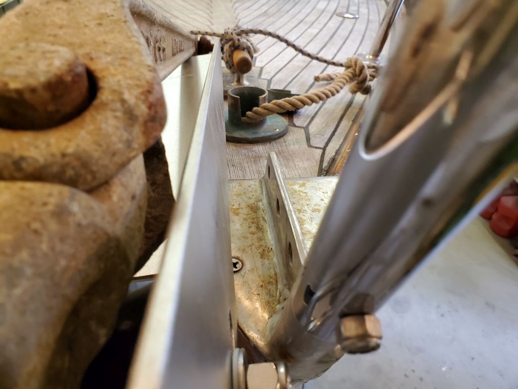
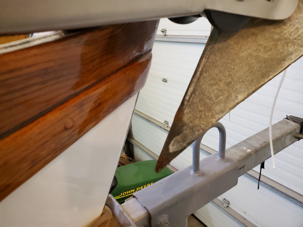
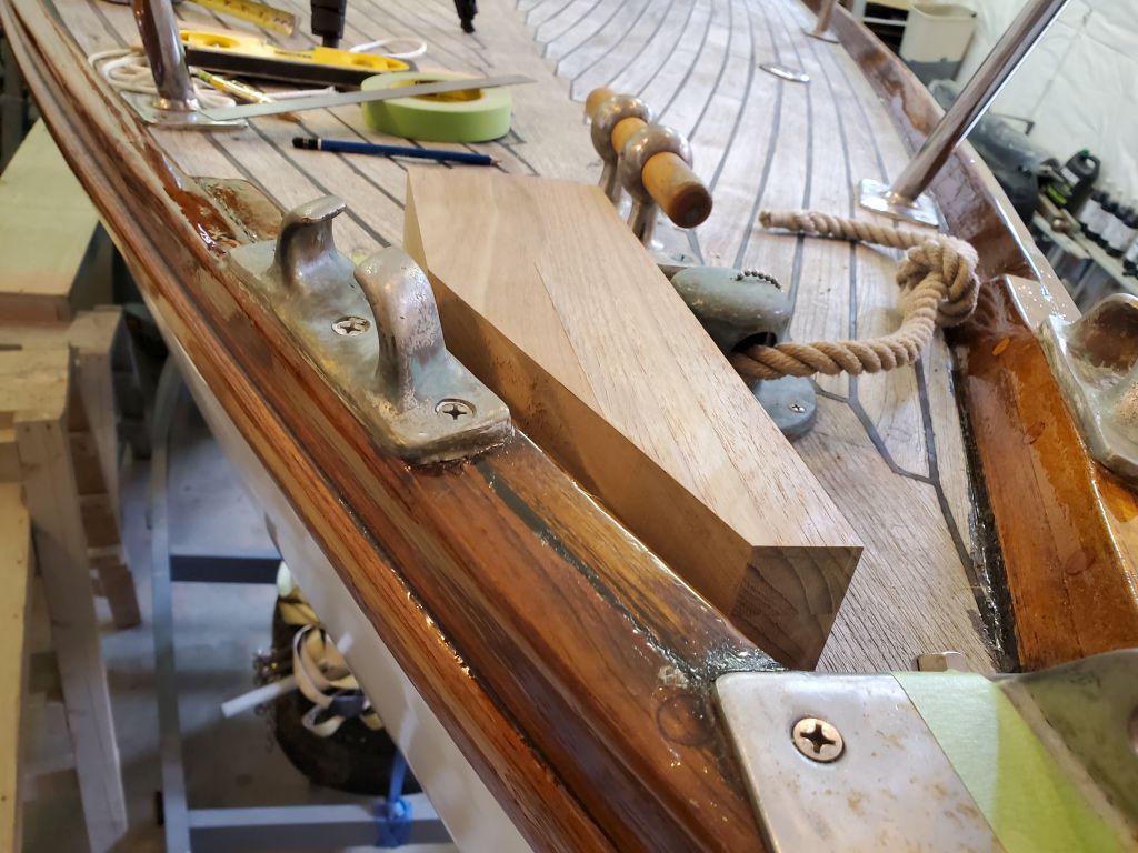
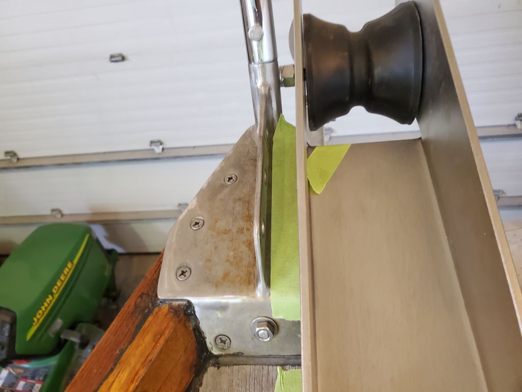
Although I’d previously determined that the roller would actually fit in the space, now, with the anchor in place, it was time to figure out just exactly how and where it should go. I started with the anchor in its expected–and most logical–position, where the pin in the roller assembly would fit through the eye of the anchor to secure it. This generally fit pretty well, and eventually I found that I could position the roller parallel to the centerline while bypassing the chock and leaving a relatively generous 1″ clearance between the roller and the stem plate. This also kept the roller and anchor shank clear enough of the cleat and hawsepipe, but in order for the rubber roller to maintain clearance with the toerail/stem beneath, I could only move the roller so far aft, as shown, and before I committed I wanted to check another position.
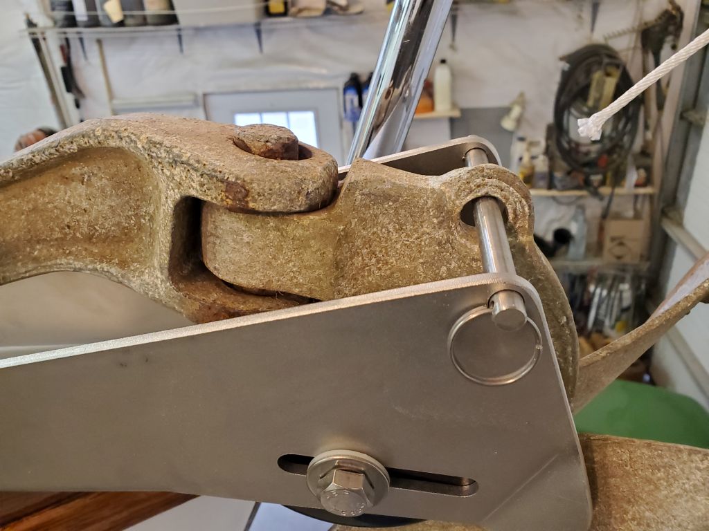
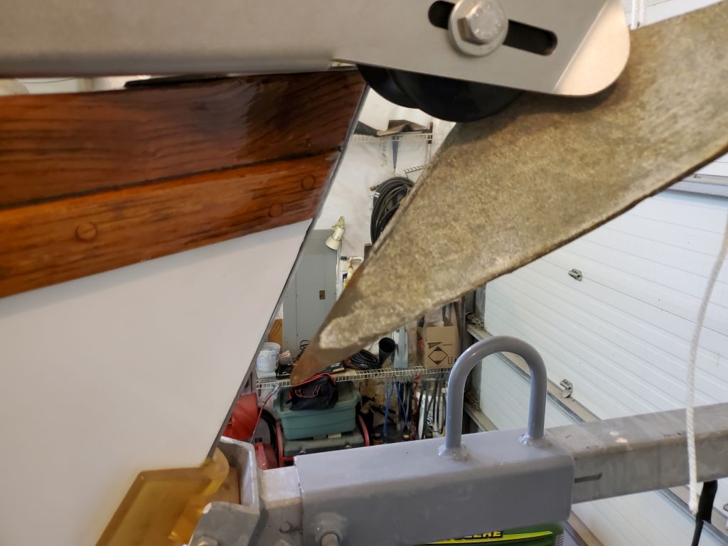
The rubber roller itself had a shaft that extended through slots on the sides of the roller frame, allowing the roller to move back and forth; potentially, having this located in a different area of the slot could be beneficial to the overall setup. So after removing the pin securing the anchor, I pulled the anchor up/aft as far as I could, allowing the roller shaft to slide all the way back, and checked the fit again. This anchor position was less ideal since it obviated the use of the pin, but if it had enough of a positive effect on the other required positions of the roller assembly, it would be worth consideration.
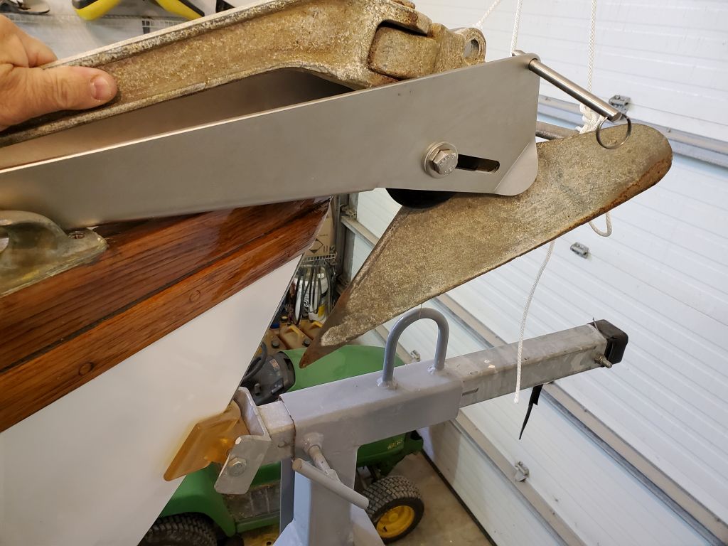
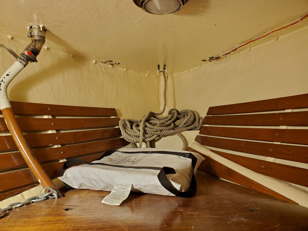
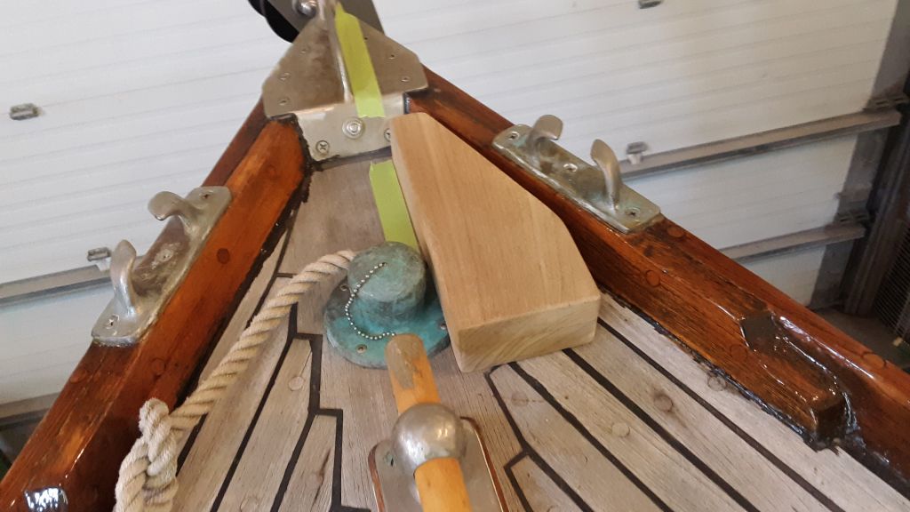
In the end, though, this change didn’t make much of a difference at all to my options with the roller, so I quickly returned the “default” position, now using some lines to secure the arrangement in place so I could do some work on fitting the support block. I also inspected the space belowdecks, in the chainlocker, so I could determine if there were any factors there that might limit my installation or space for bolting; fortunately, this space was wide open, other than known obstructions (same as on deck), so I could proceed with the block fitting as needed.
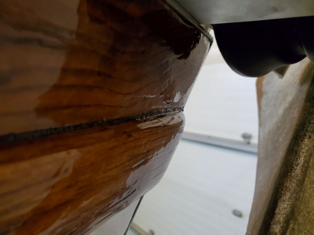
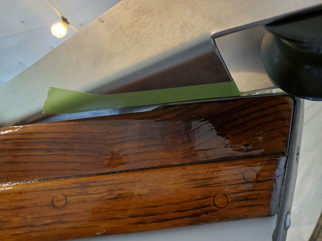
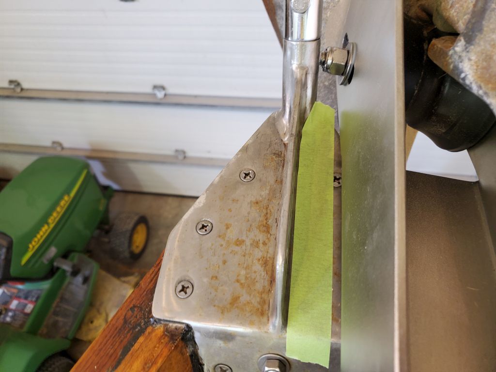
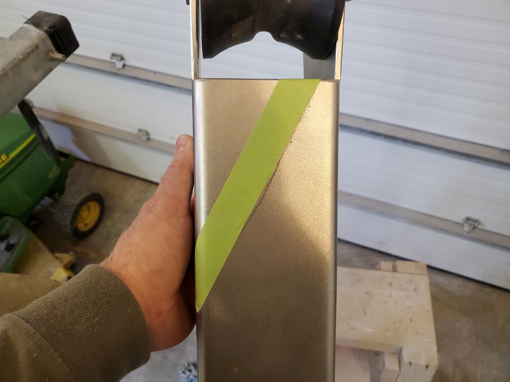
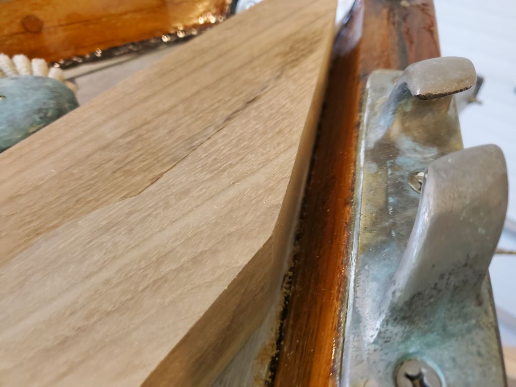
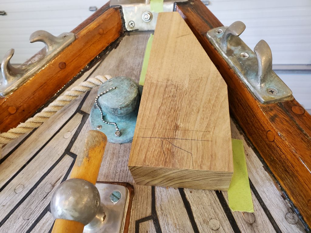
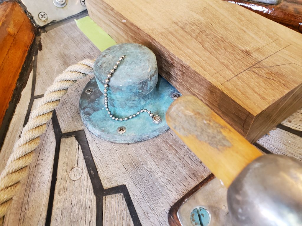
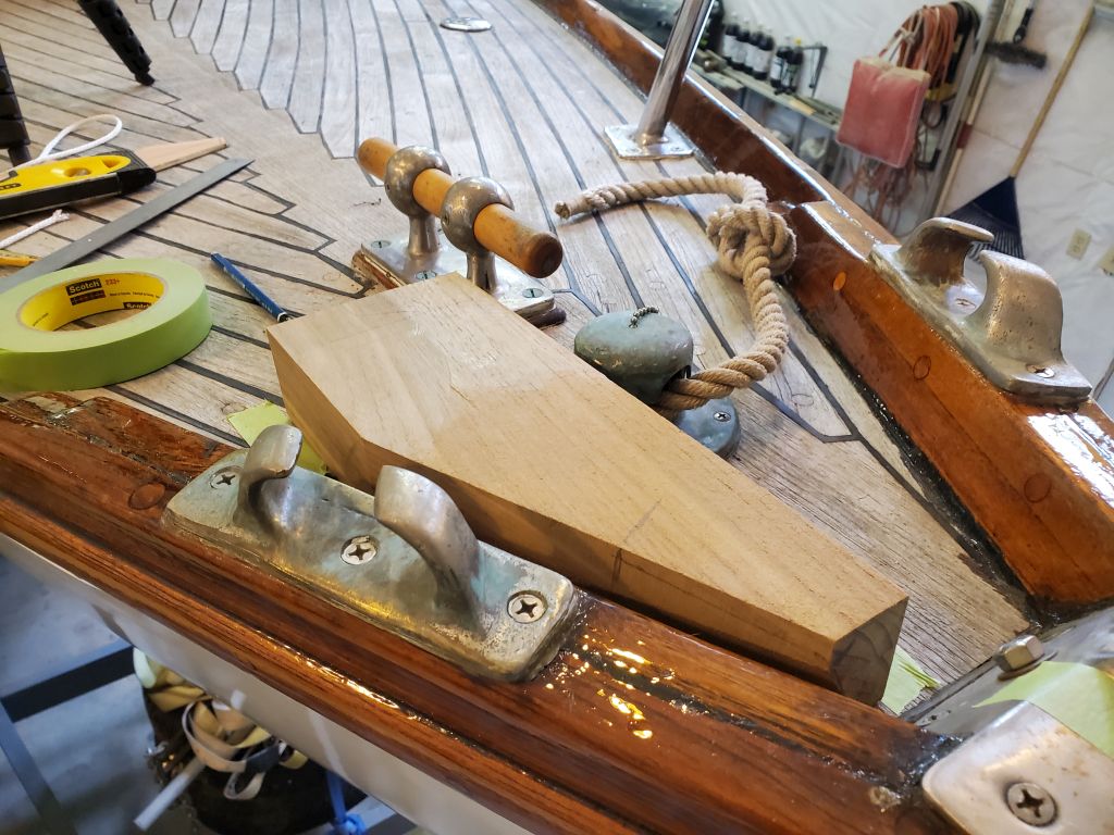
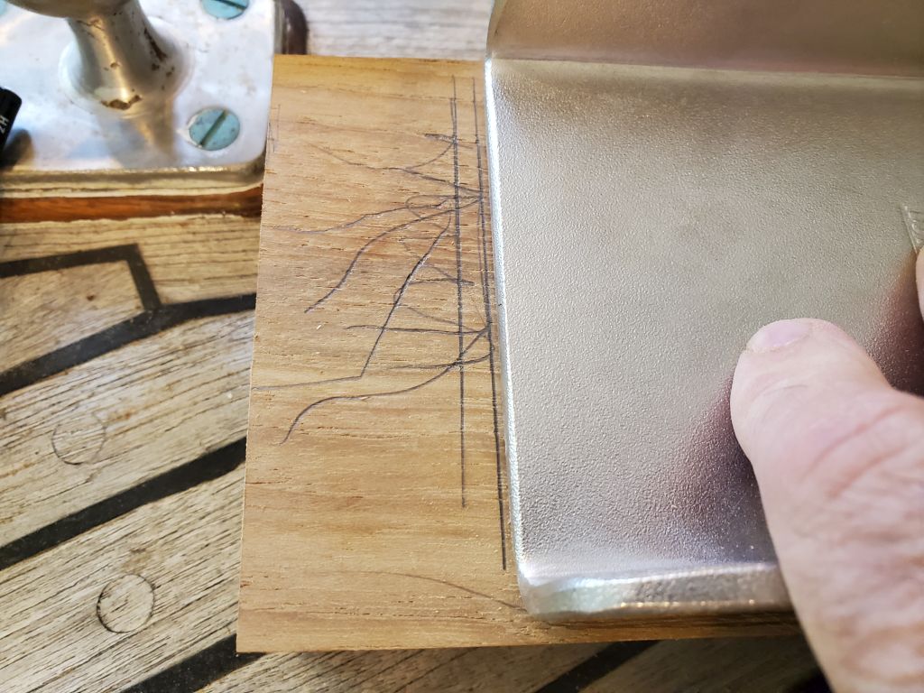
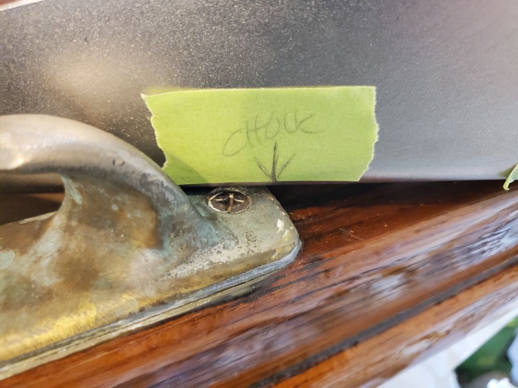
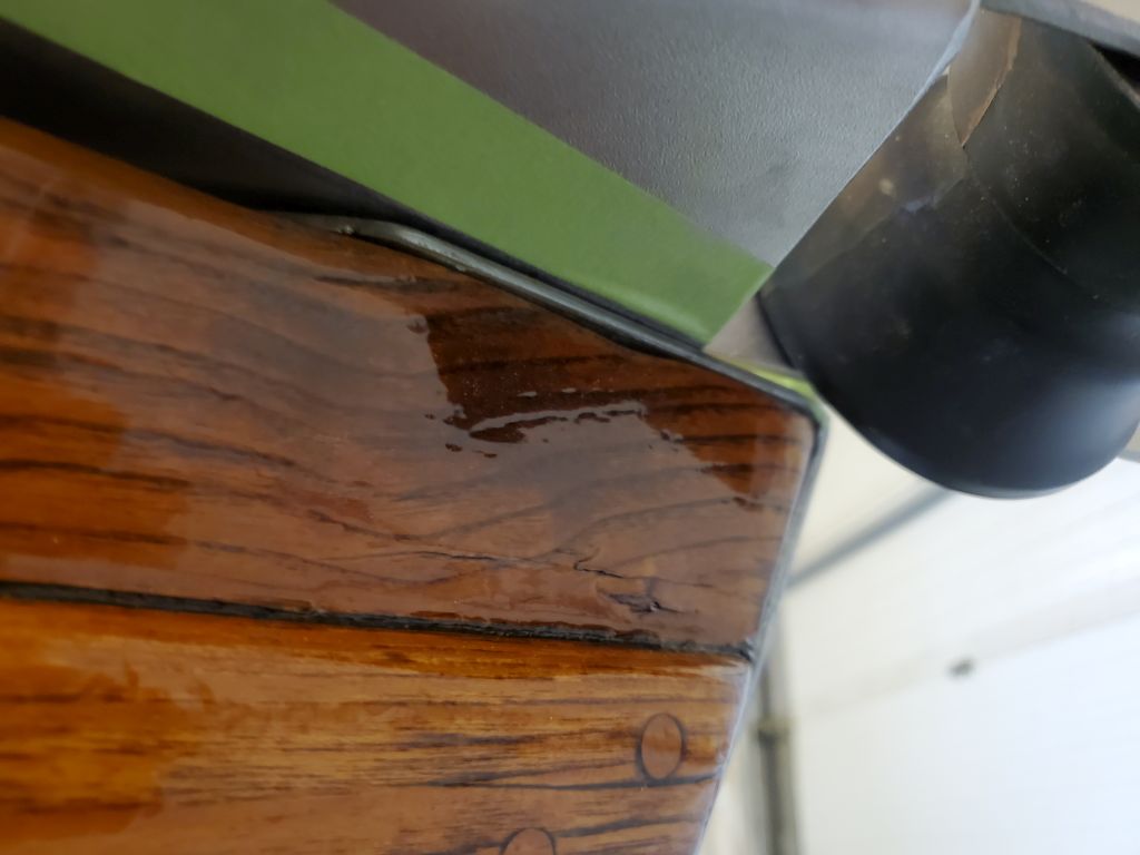
With the anchor still pinned in the roller, I finalized its position so I could make a couple reference marks: one along the edge of the stem plate, where I used a strip of 1″ tape to show the position (providing 1″ of clearance there), and again beneath the roller, where I marked its exit from the stem plate with a pencil first, then a piece of tape. These marks would help me align the roller properly ever time I moved it to template the support block.
With that done, I could remove the heavy anchor from the roller for the duration; to keep it handy, I hung it over the ladder at the forward end of the trailer, tied in place so it couldn’t move.
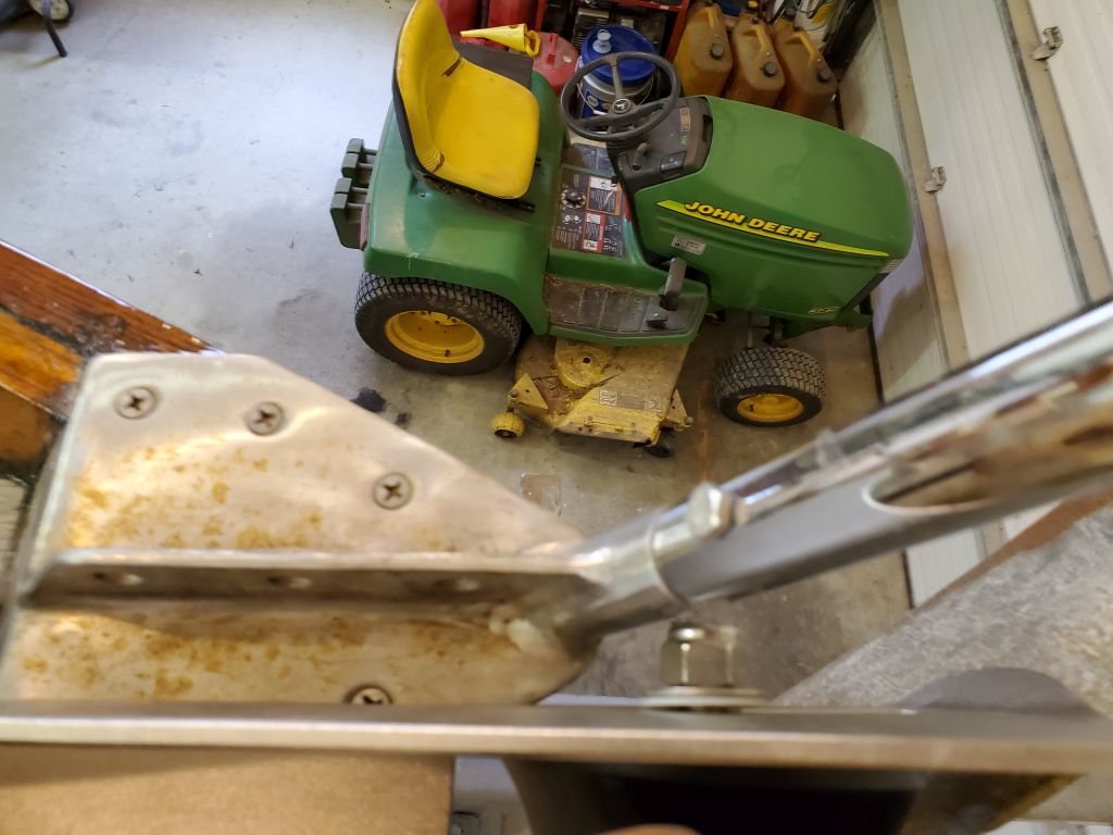
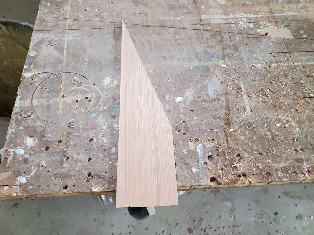
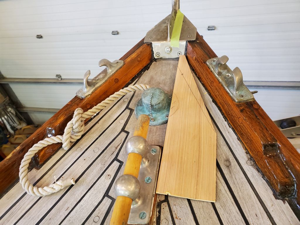
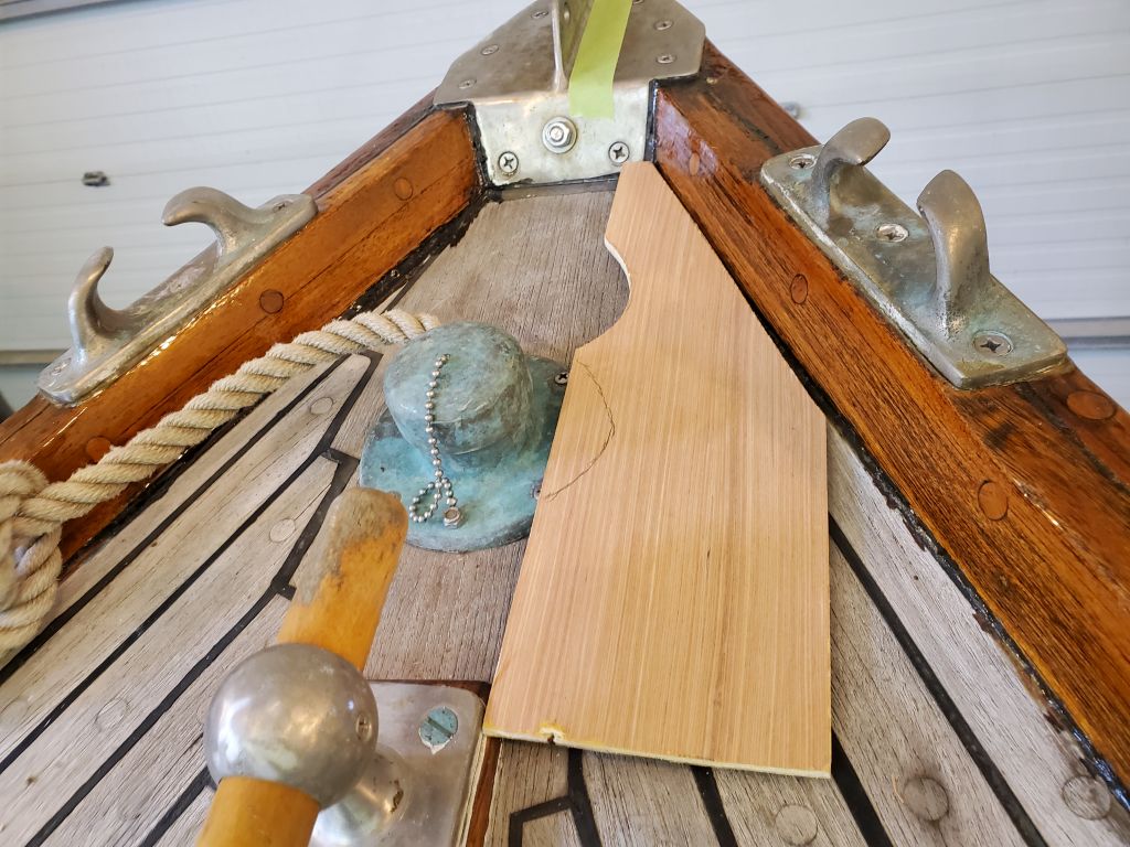
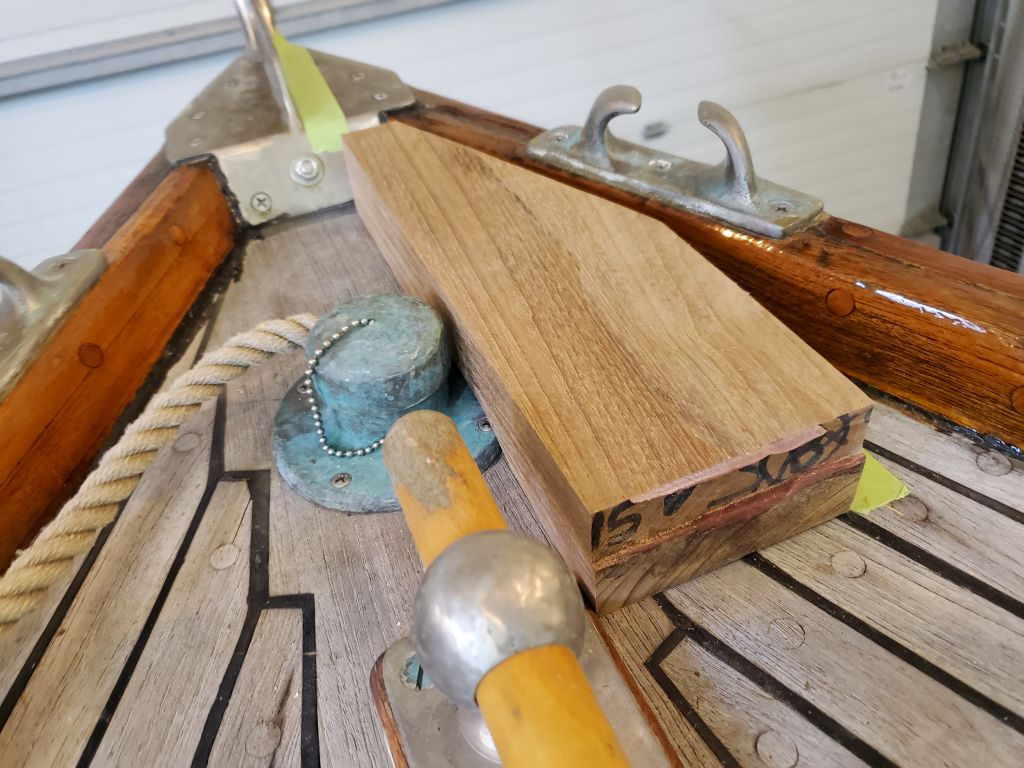
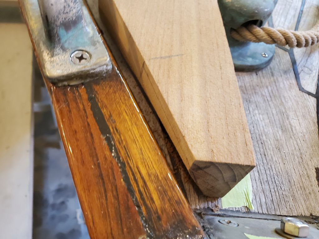
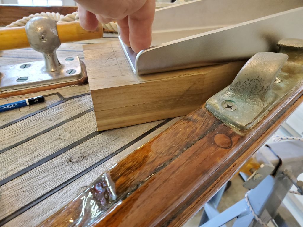
I made a 1/4″ plywood blank of the same width as my support block, and pre-cut a steep angle at the forward end to help it fit initiall7 in the space. Over a few fits and cuts, I eventually brought it in closely to the stem and toerail on the starboard side, and marked where it interfered with the flange on the hawsepipe fitting; this area would need to be shaped and relieved from the bottom of the teak block itself.
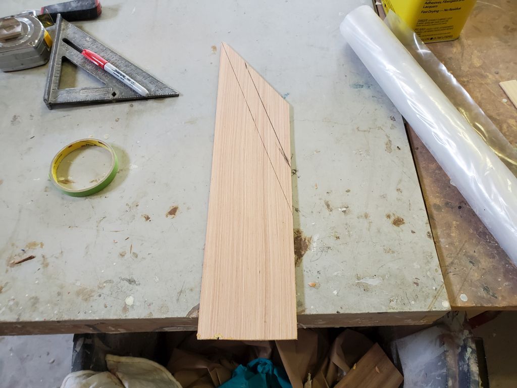
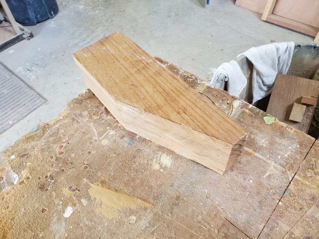
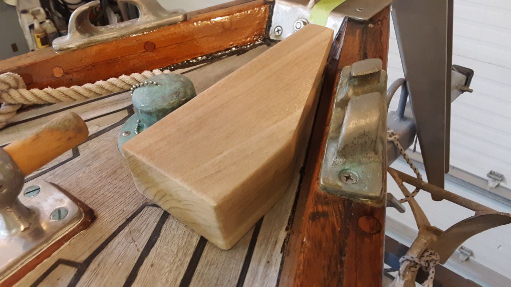
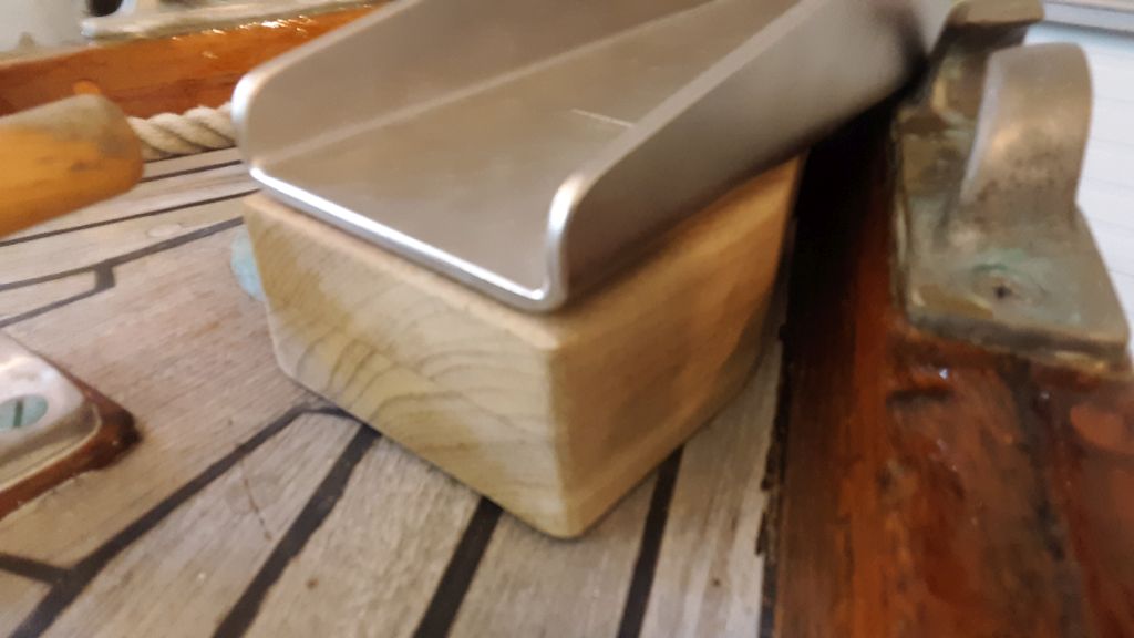
I used this template to help create the initial shape of the support block, which I eventually, over various fittings and minor modifications, cut and shaped to fit the space, both on deck, against the stem and toerail, and the overall height. Ultimately, I decided to leave a channel for water and air circulation on the two outboard edges of the block: against the stem and toerail. Fitting the block exactly against these two surfaces served no real purpose, and would have taken many more time-consuming fitting steps, and unless the fit was exact, there were opportunities for water and debris collection. So instead, I left a clear path around the support block to maintain water and air flow. This still left as much of the block as possible to be used for actual support and securing of the roller assembly.
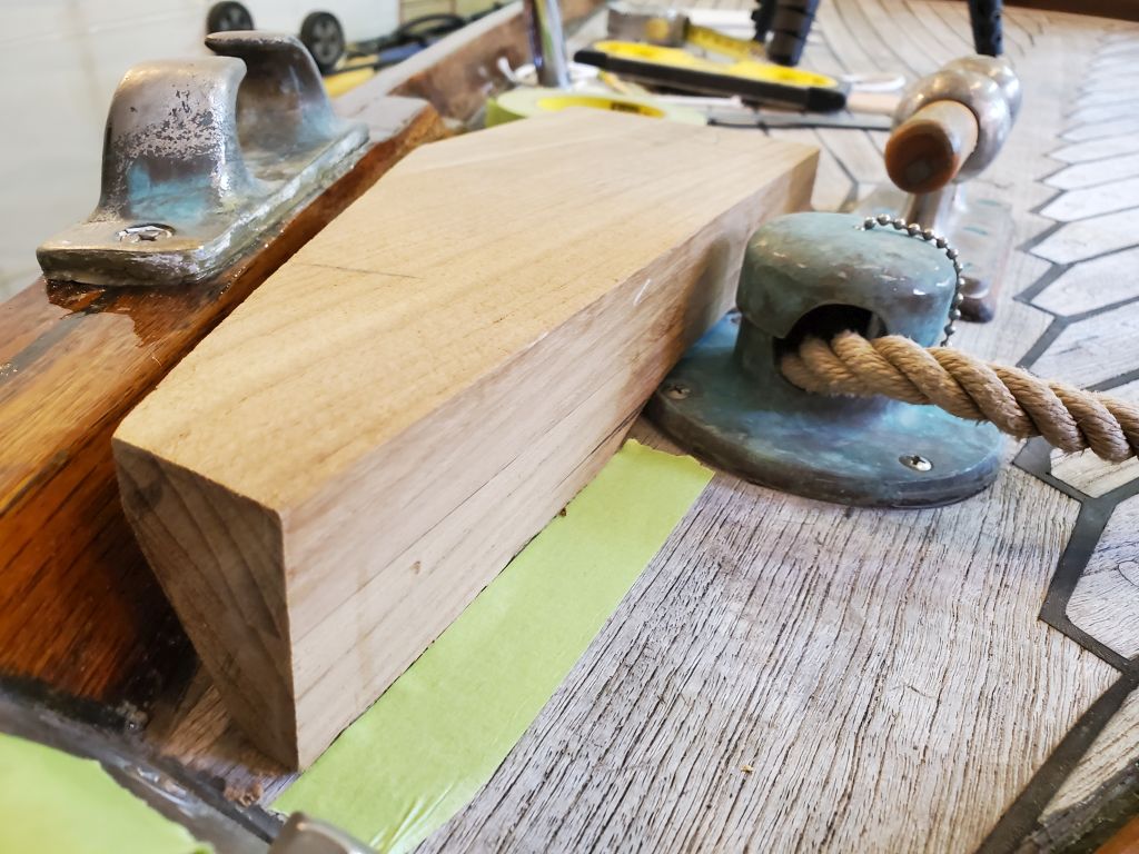
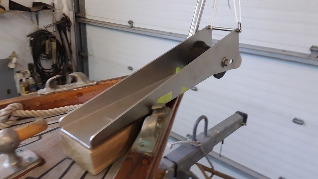
This took many backs and forths for various cuts and shapes, placing the roller on the block each time to check the overall orientation and fit. Eventually, this allowed me to finally mark the aft end of the roller, so I could make the final cut on the support block (I’d left the aft end as long as possible throughout to give me enough material at the forward end as I shaped it to fit).
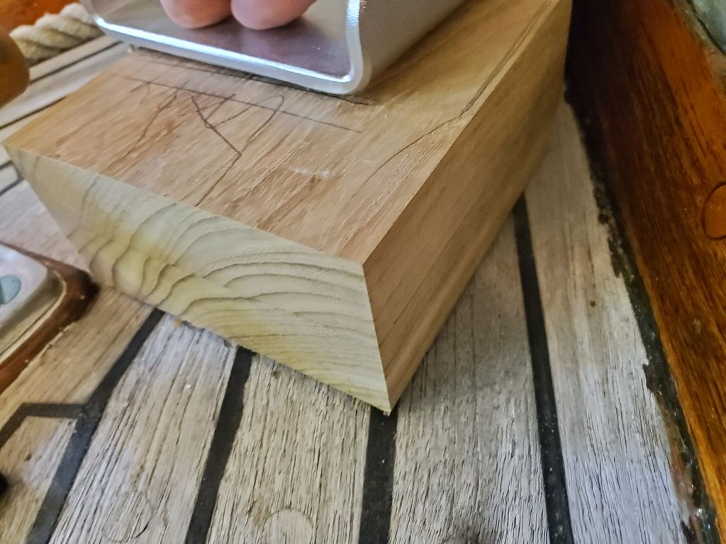
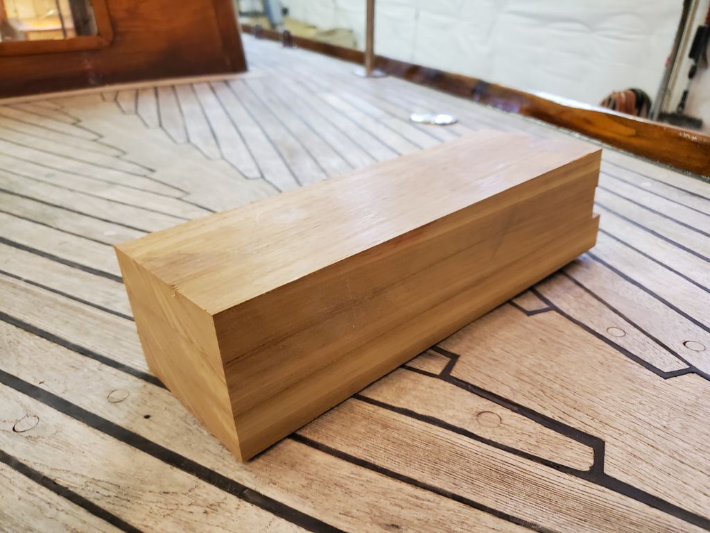
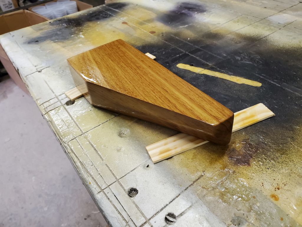
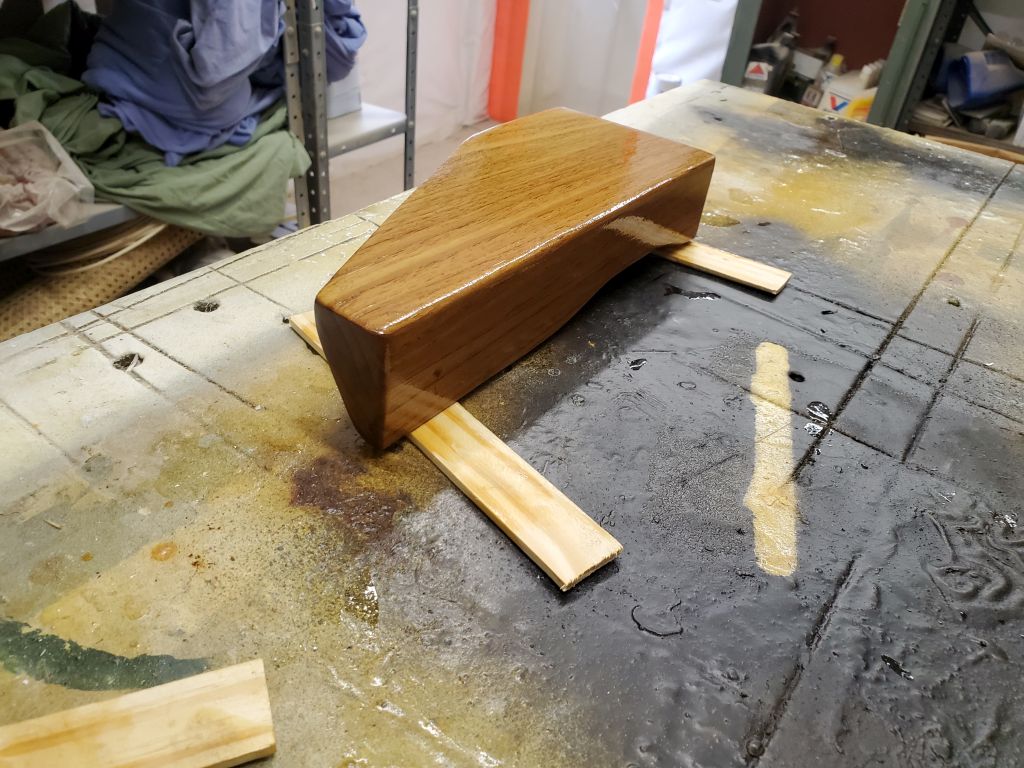
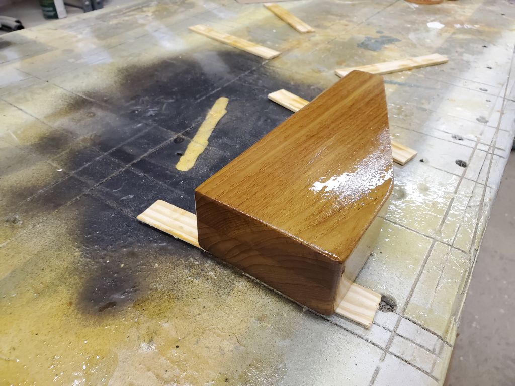
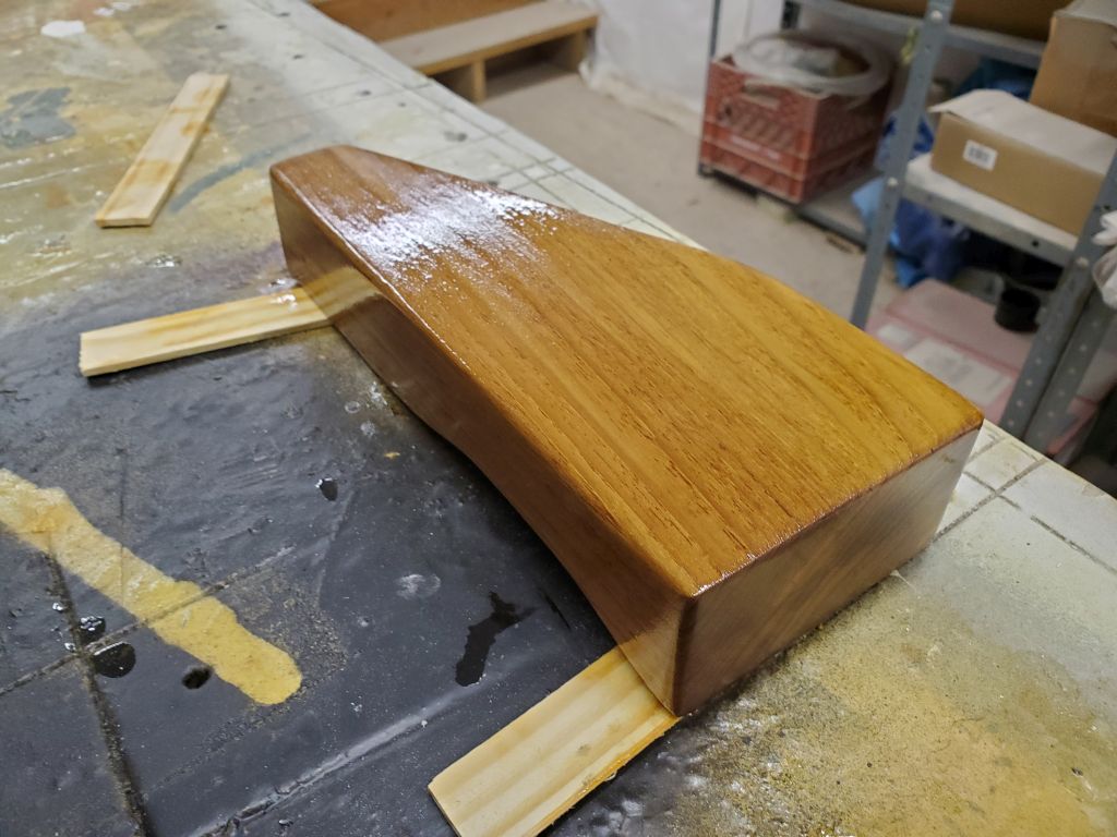
In the woodshop, I cut the block to length, then sanded it smooth and lightly rounded all the corners. Most of the block would be hidden and inaccessible in the final installation.
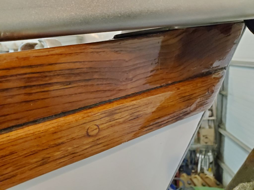
Before final installation, I wanted to varnish the block, so I got started now with a sealer coat on all sides.
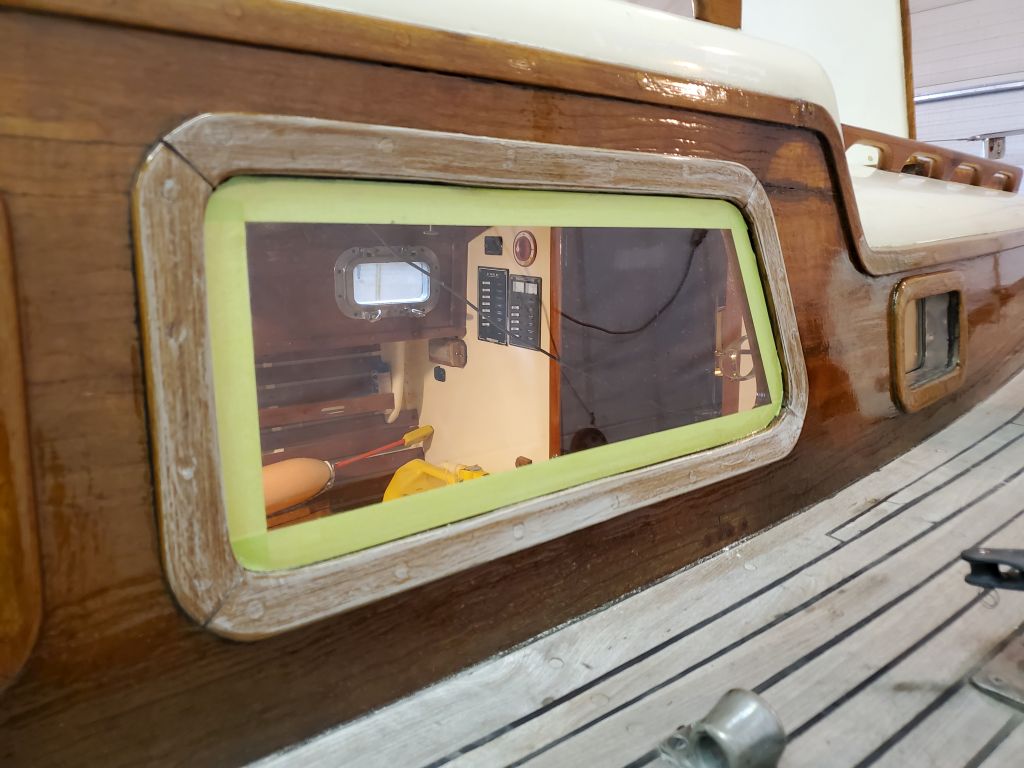
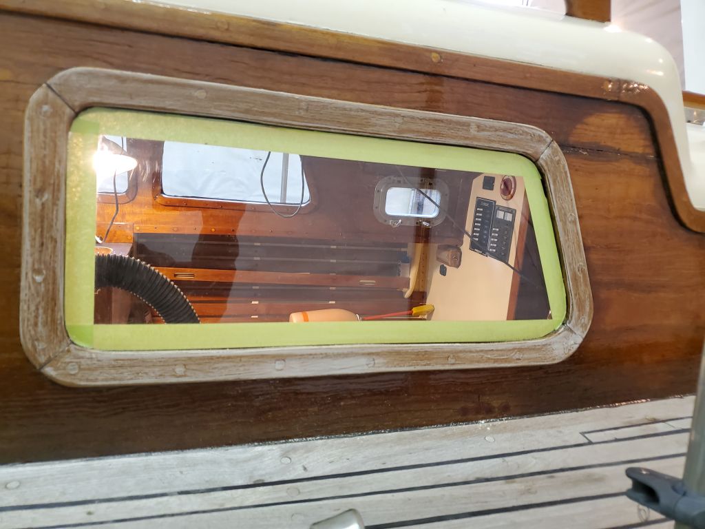
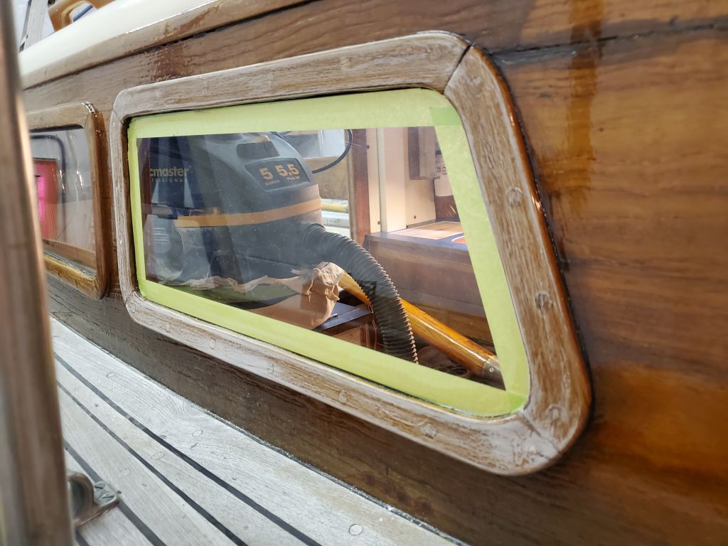
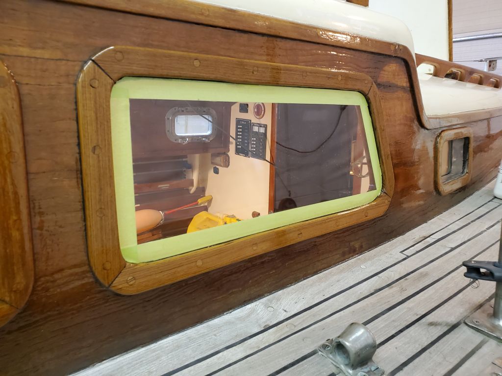
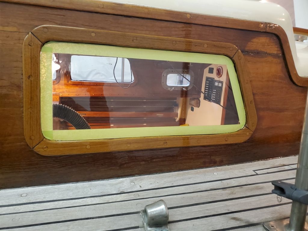
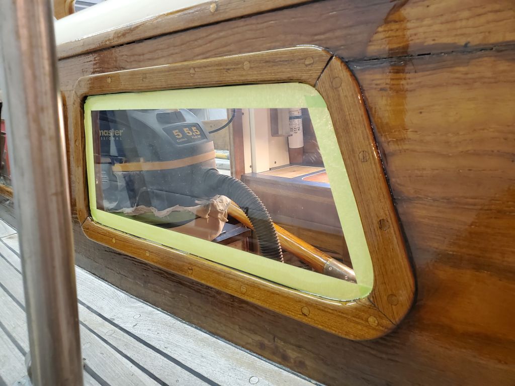
In other works, I continued the extra varnish work on the new starboard deadlight trim, lightly sanding and applying another coat. I’d hoped to do a couple coats over the weekend, but didn’t get to it.
Total time billed on this job today: 5.25 hours