
110 Cookson Lane | Whitefield, ME 04353 | 207-232-7600 | tim@lackeysailing.com
I decided to leave the glued-up rough deadlight frames in the clamps for another day, seeing no need to rush back into the work on the frames; I had plenty of work ahead on the engine foundations.
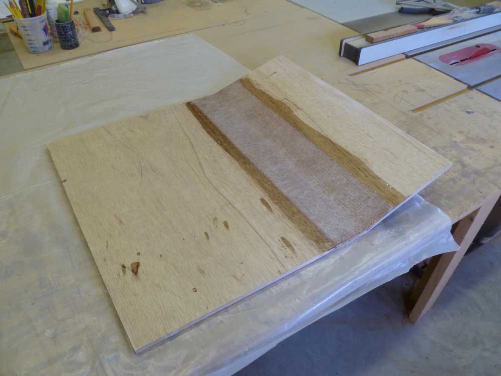
First, though, I removed the plywood base from the fuel tank, now that the fiberglass and epoxy had cured, turned it over, made necessary preparations, and installed a layer of tabbing on the other side to further reinforce the joint.
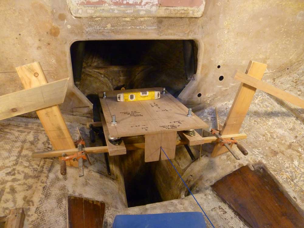
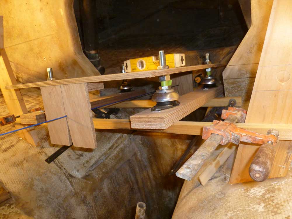
I now had the flexible mounting feet for the diesel engine on hand, which were critical to the next stages of layout. While I could have, had I needed to, made mockups for the feet, having the actual ones on hand made these steps easier and ultimately more accurate. I adjusted the four mounts to a consistent level that would allow adjustment in both directions, and secured them to the plywood engine template. The bottom side of the template was actually the reference criterion for all template measurements, and represented the bottom of the steel mounting flanges on the engine itself, so having the flex mounts secured in this way meant that the template acted just as would the engine.
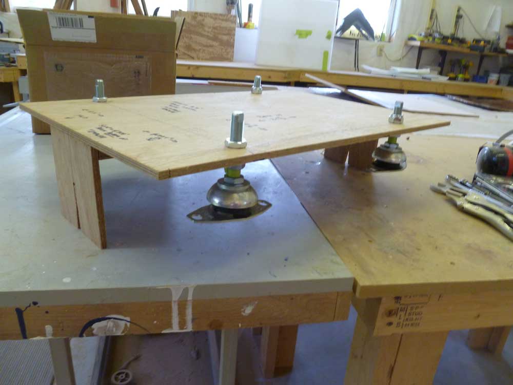
To simulate the engine foundations in length and width for the final layout work ahead, I constructed two plywood strips, each 1" thick, 2-7/8" wide and just under 24" long, which I could clamp to the bottoms of the mounting feet as needed. The plywood also simulated the top portion of the final engine foundations, which I planned to cover with a section of prefabricated epoxy laminate (G-10), though I was soon to decide to use a 1/2" thickness rather than 1", but this meant only that I had to subtract 1/2" from all my measurements taken later in the process. Details on all this will become clear as things progress.
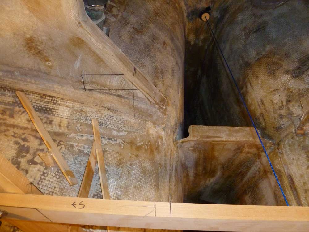
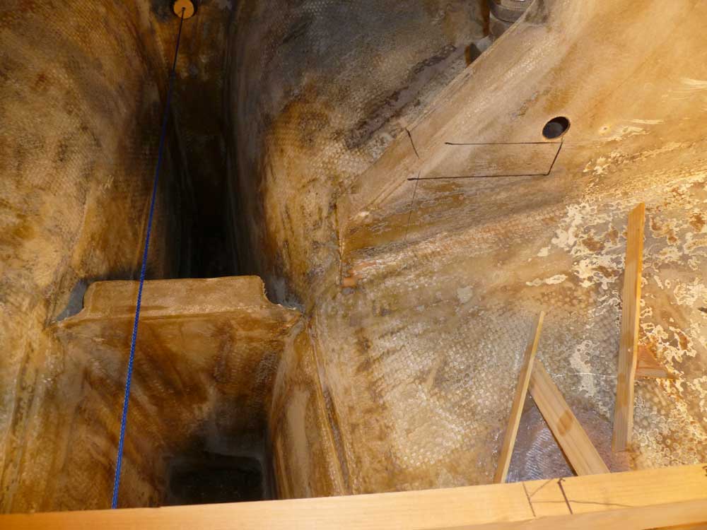
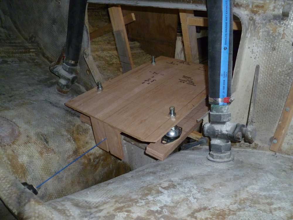
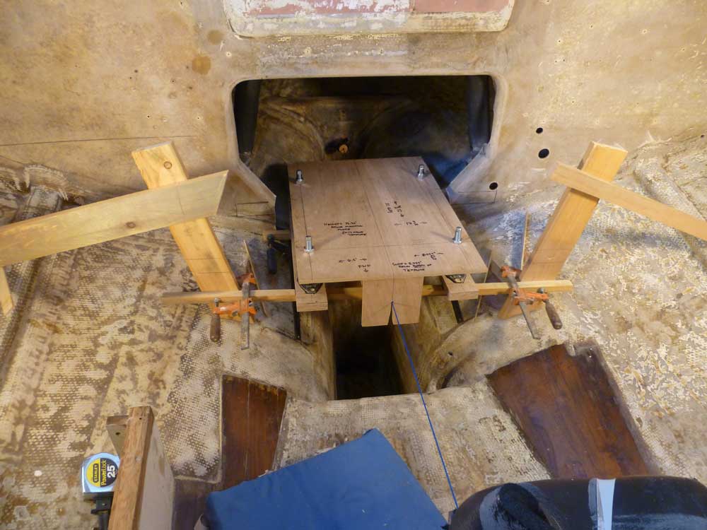
Up in the boat, I placed the template on the supports I'd installed previously, letting the feet hang down as needed. After aligning the template carefully on the alignment string, and double-checking everything, I made some marks on the fiberglass bulkhead at the center part of the engine room, which I'd need to cut partly away to provide room for the new engine foundations. Then, I removed the template and cut the bulkhead to my marks. Sometime later, I'd reinforce the cut ends and probably tie them into the new engine foundations, once installed.
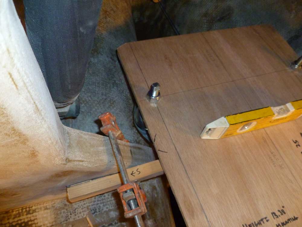
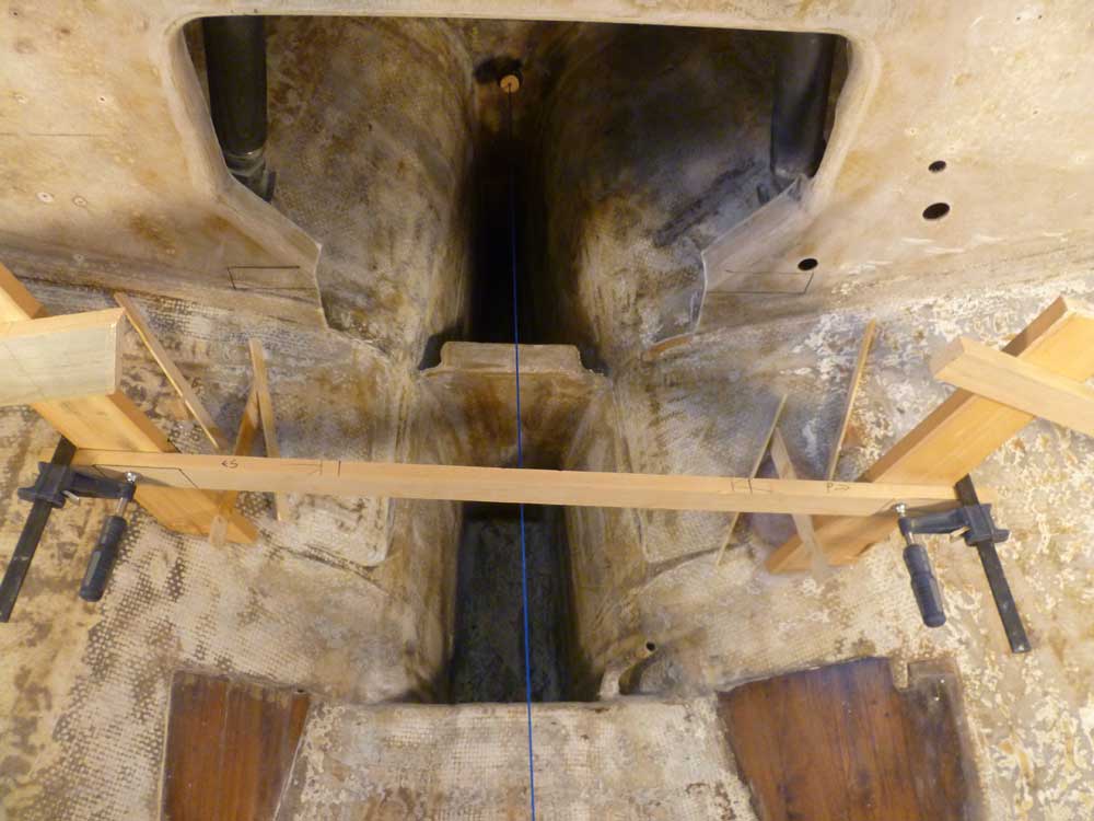
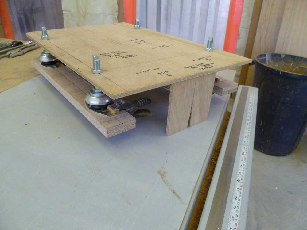
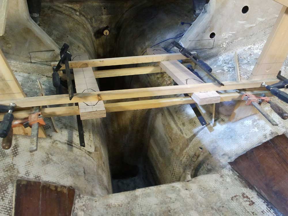
Next, I set the engine template back up and aligned it carefully once more, then clamped the plywood boards to the bottoms of the feet, positioning them according to some marks I'd made down on the bench earlier. With everything secured and properly positioned, I cut and installed two new support braces just below the plywood, which allowed me to remove the original supports and let the template sit on its mounting feet, much the way the engine would later sit on the foundations themselves. I moved things around, forward and aft, as needed till I was happy with the overall placement of the simulated foundations and engine template.
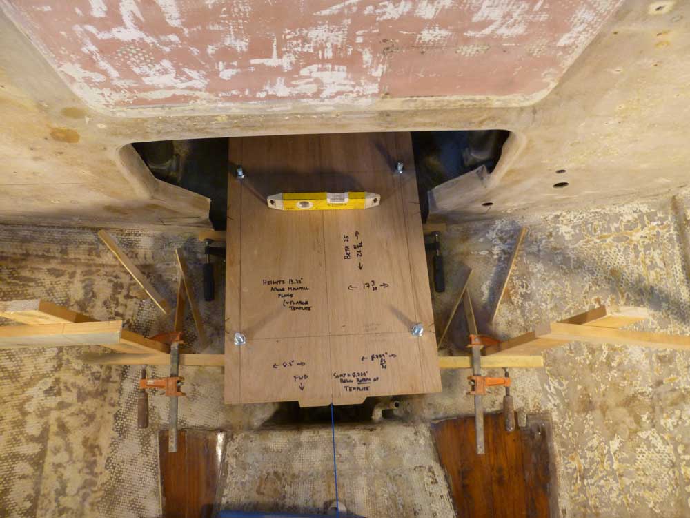
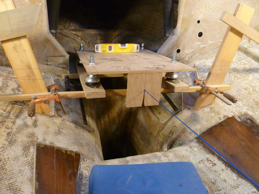
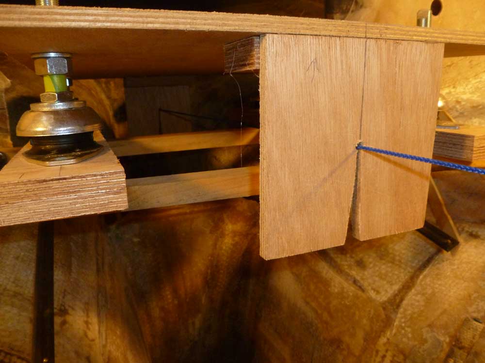
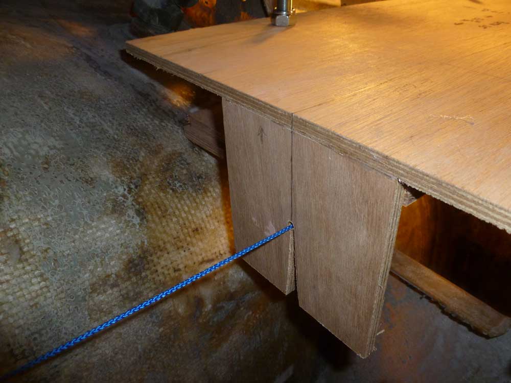
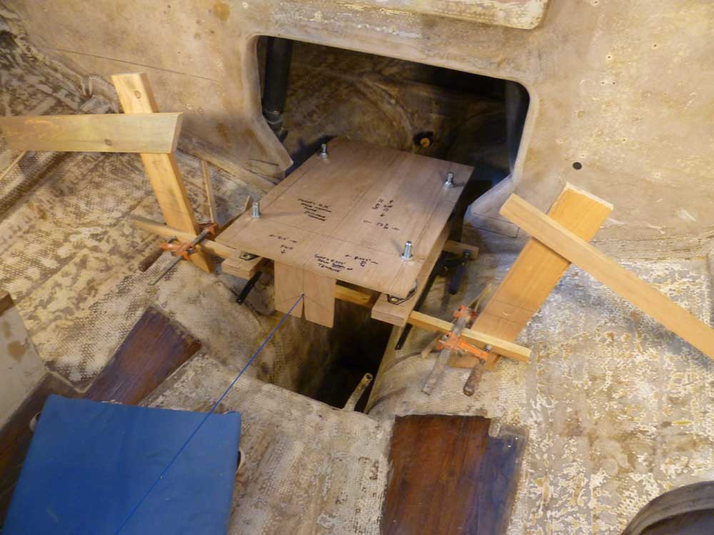
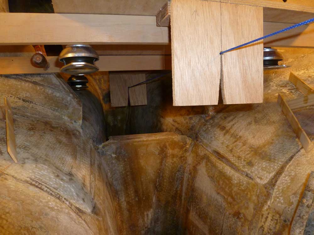
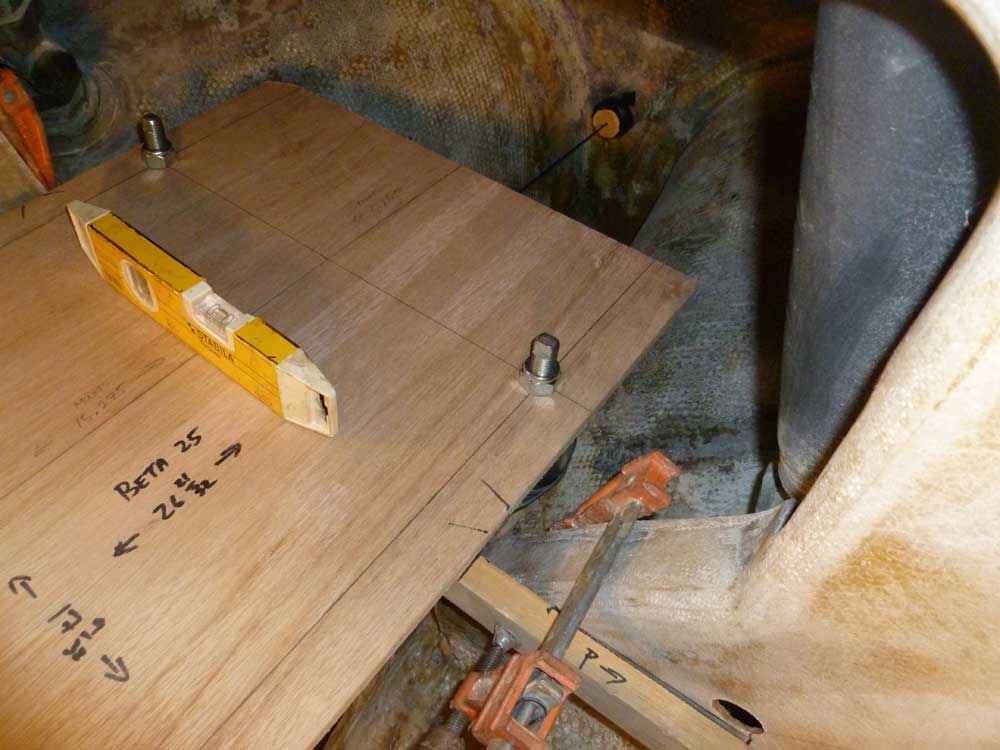
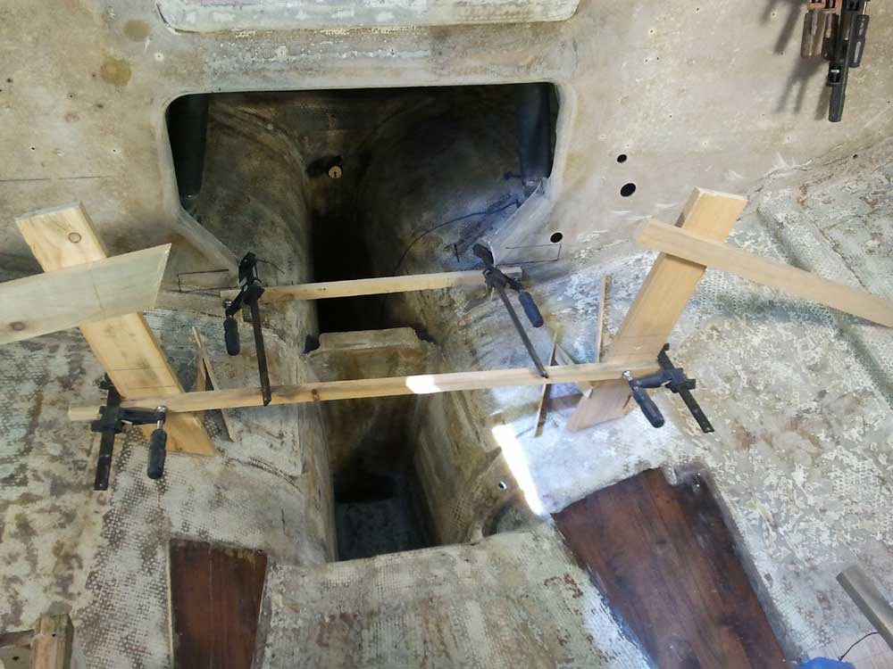
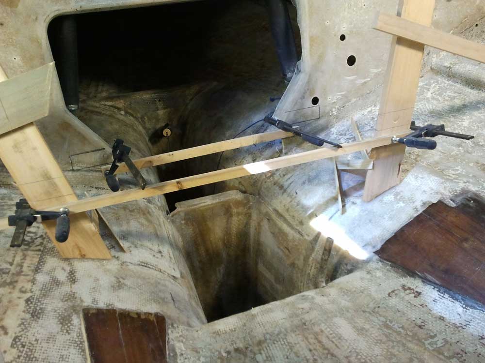
There was one more critical support/layout change to make. Now that the engine template was properly supported on top of the new braces, I checked the layout and alignment once more, then made reference marks on the plywood boards where the mounting feet rested (this more for ease of measuring during later steps). Then, I removed the engine template, leaving the plywood boards in place. I clamped these in position so I could use them to make the vertical measurements I needed from each corner of the plywood down to the hull directly beneath, which represented the height of the engine foundation in each area. With four cardinal measurements for each side, I could lay out the cuts on the foundation blanks.
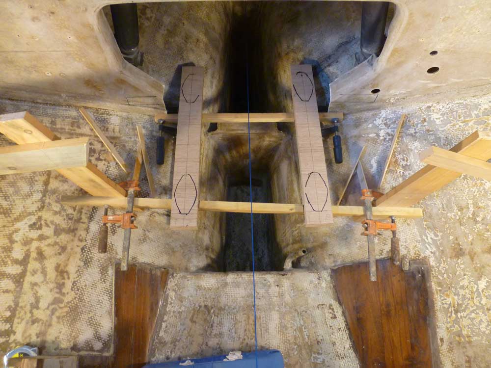
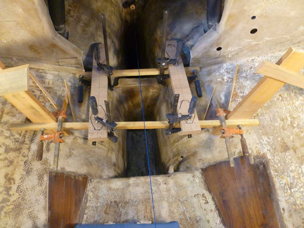
Finally, I clamped level cross pieces across the tops of the plywood; the bottom edges of the new braces, therefore, represented the very top of the engine foundation, and would provide positioning reference during installation, as well as give me a means of securing the foundations temporarily while adhering them to the hull.
Using the measurements I'd taken earlier, and subtracting a half inch (to account for my change from 1" fiberglass on the tops of the plywood foundations to 1/2"; more on this later), I laid out the cuts on the two plywood blanks I'd built last week.
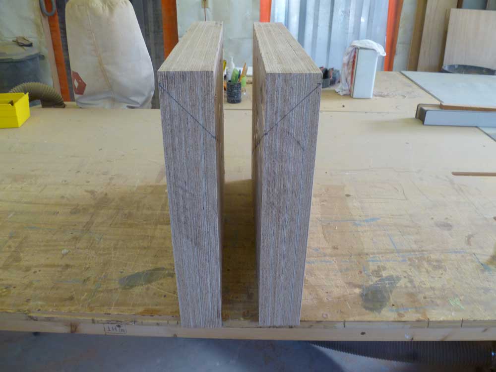
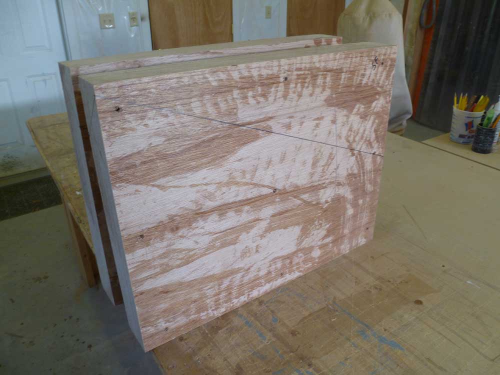
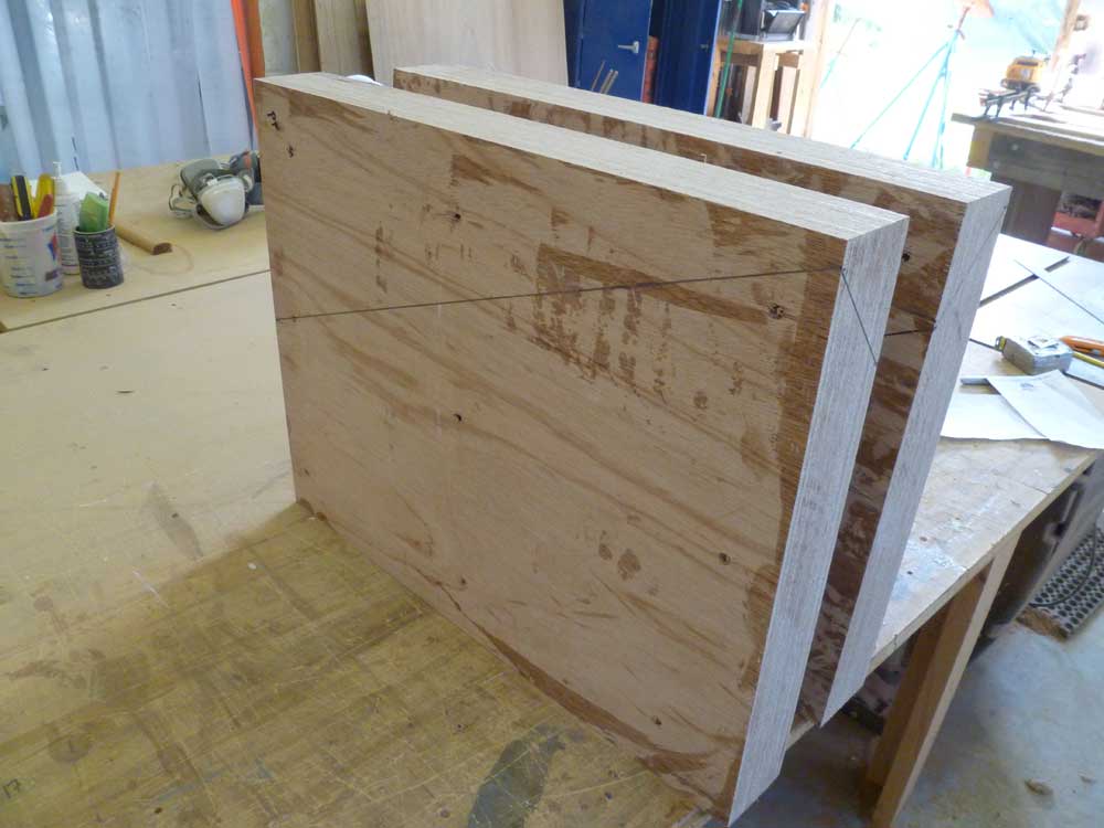
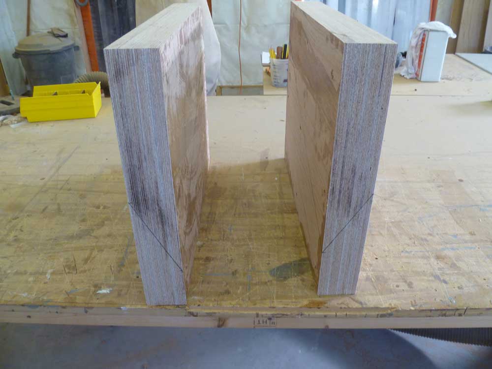
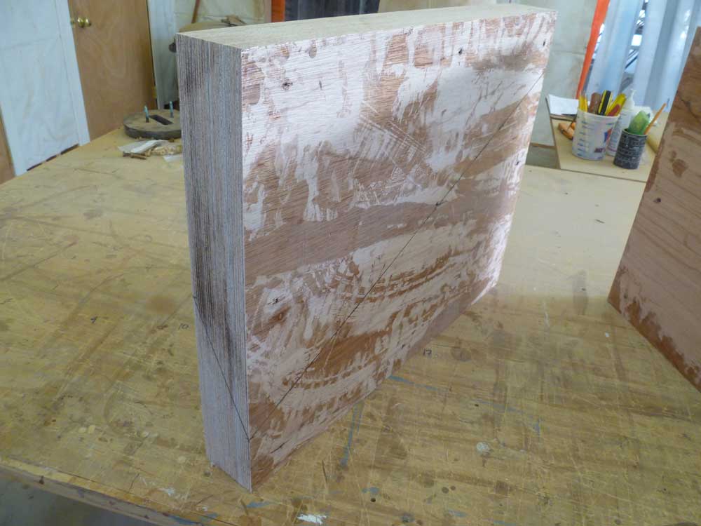
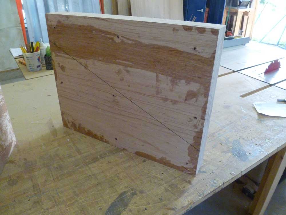
Finally, I trimmed the blanks to these lines using a saw, planer, and sander as needed to make the compound-angled cuts.
Total Time Billed on This Job Today: 7.25 hours
