
110 Cookson Lane | Whitefield, ME 04353 | 207-232-7600 | tim@lackeysailing.com
I spent what seemed like an ungoodly amount of time spec'ing out and ordering the fittings required for the fuel tank, so that I could eventually connect what I needed to to the various threaded holes I'd specified on the tank itself, and in the way I intended. The tank featured a fill pipe to the cockpit, as original, plus connections for fuel supply and return and vent, as well as a drain fitting, and each connection required a different configuration depending on intended function and intended hose size.
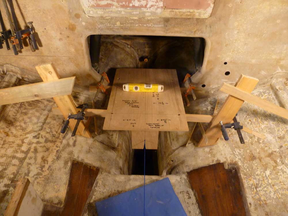
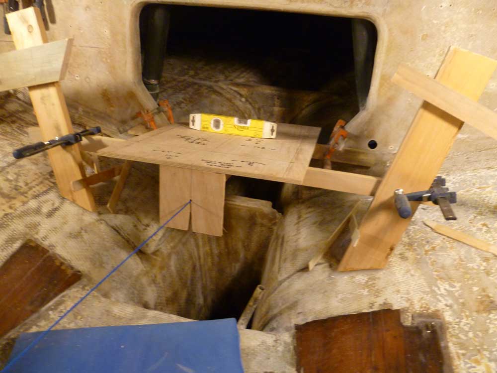
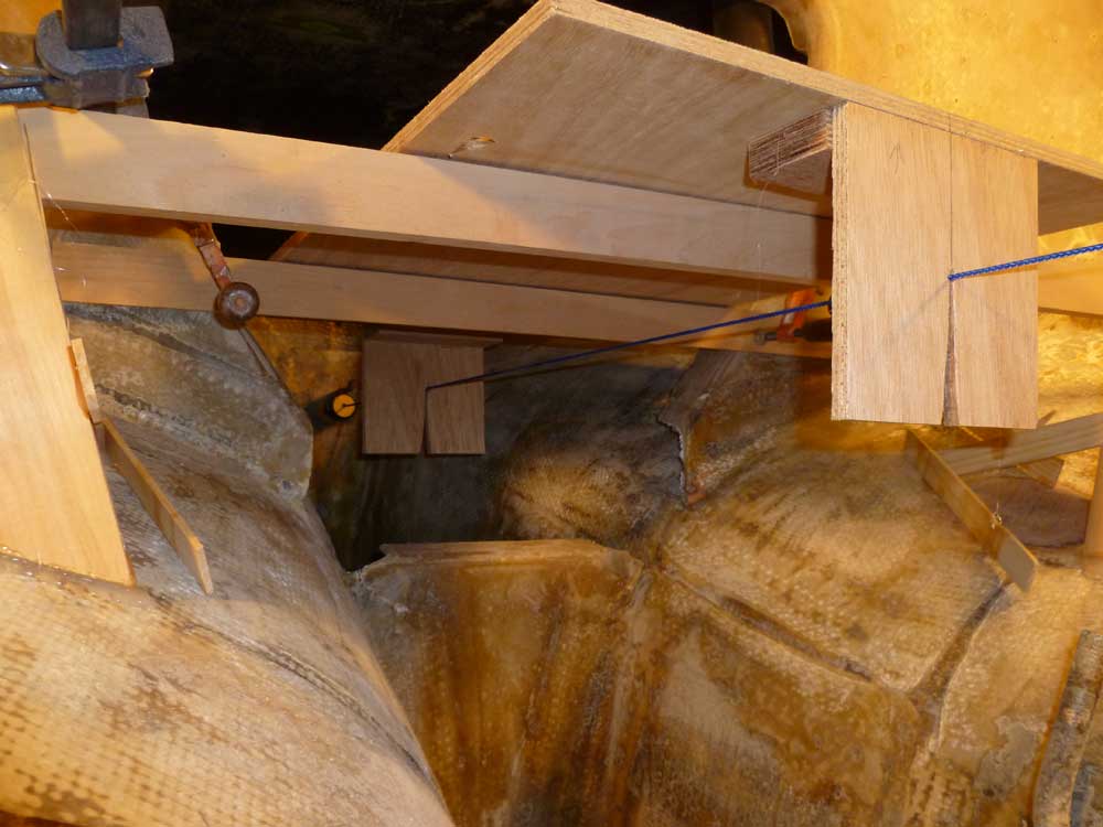
With that task complete, I returned to the engine foundation and template layout. While yesterday's cat's cradle of string had gotten the template more or less in the right location, I needed something more stable and accurate before I could proceed, so during the remainder of the morning and early part of the afternoon I created simple support braces and adjusted the template till the prop shaft center string ran cleanly through the holes representing the center of the shaft coupling on the engine.
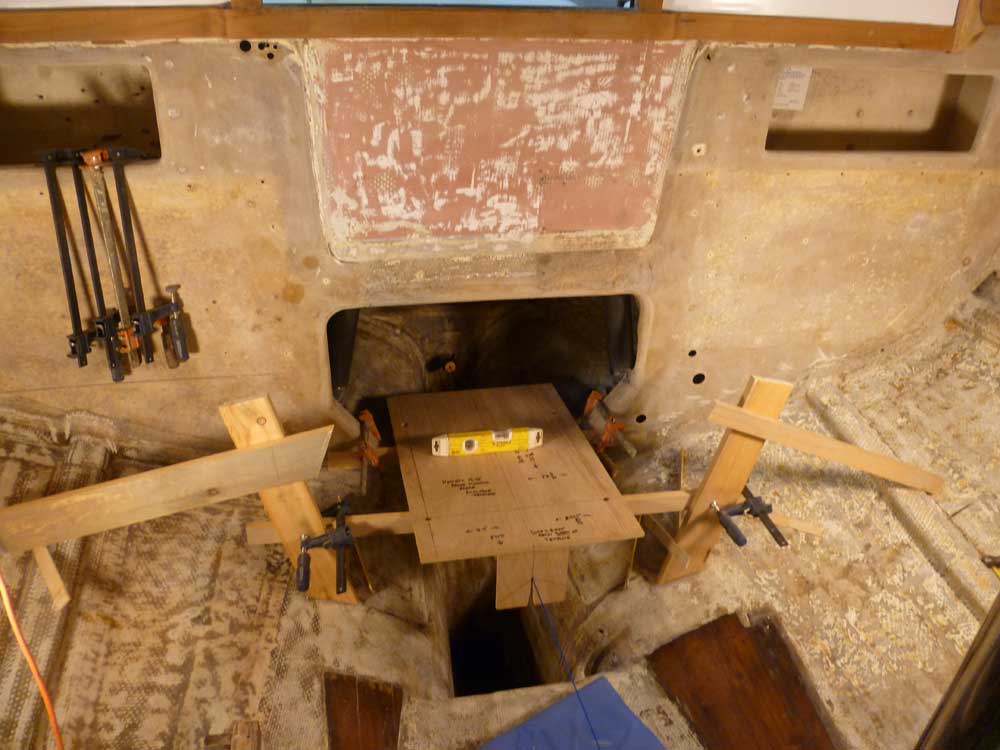
In its current position as shown in these photos, the "engine" is positioned with its forward edge just a bit aft of the vertical bulkhead defining the after end of the keel water tank, where the deep bilge begins; the aft edge, representing the face of the transmission coupling, is approximately 12" forward of the stern tube. At first glance, this seemed like it could be a good position for the engine, but this was subject to further adjustment before all was said and done. There was plenty of room beneath the template for the engine oil sump and transmission protrusions.
I hoped to ensure enough space behind the engine to make stuffing box maintenance and shaft coupling removal as easy as possible--not to mention simply possible--while also minimizing the protrusion of the engine into the cabin. However, the final engine placement would eventually drive the construction and design of the new galley, so we weren't artificially tied to any internal or cabinetry constraints. There appeared to be more than enough vertical clearance above the template; the engine height at its highest point would be roughly 13" higher than the top of the template, and I had 14" to the top web of the bulkhead opening.
The tops of the actual new foundations would be roughly 2.5" - 3" below the plywood template, to account for the height of the adjustable flex mounts on which the engine would actually rest; I'd accommodate this adjustment when the time came to actually cut and fit the new foundation.
This complete, I made some basic measurements for the new foundations, then sawed up a sheet of 18mm marine plywood into a series of blanks the correct size (8 total; four per side). While I was at it, I rough-cut two other sheets of plywood that I'd be using in the near future for other tasks.
Finally, I laminated the blanks together with epoxy, into two glued-up blanks each comprising four layers of the plywood, and generously oversized to allow trimming and cutting into the proper angled, tapered shape later. I drove long screws through both sides to clamp the laminations together, and set the blanks aside to fully cure.
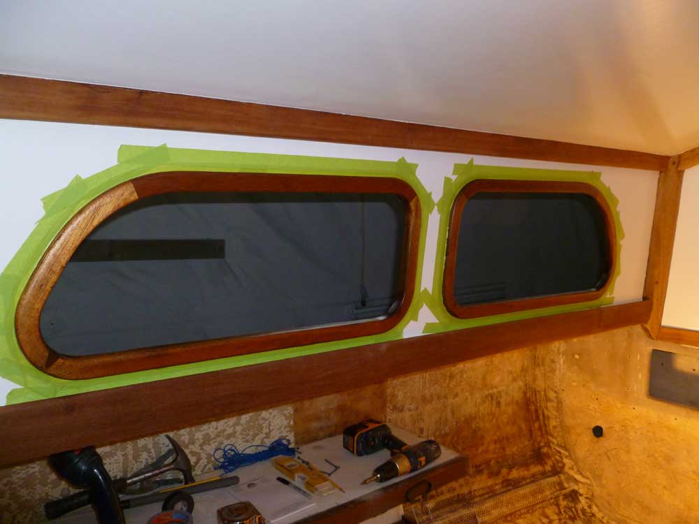
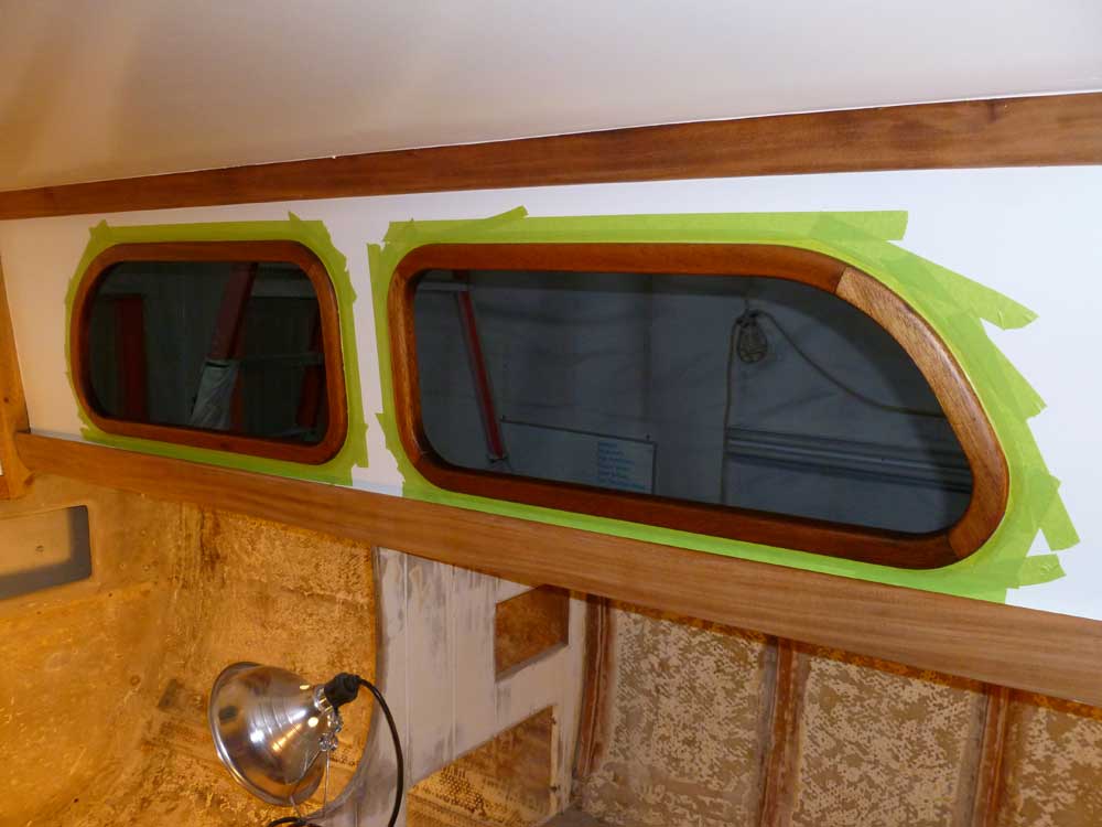
Finally, I applied one more coat of varnish to the inside deadlight frames--satin this time. I didn't varnish the cockpit this time around, but expected that this would be the last coat of varnish on the frames before I turned to the exterior frame construction and, eventually, deadlight installation over the coming days.
Total Time Billed on This Job Today: 6.5 hours
