
110 Cookson Lane | Whitefield, ME 04353 | 207-232-7600 | tim@lackeysailing.com
Over the weekend, I applied another coat of varnish to the eyebrow pieces, so with two base coats in place they were ready for installation.
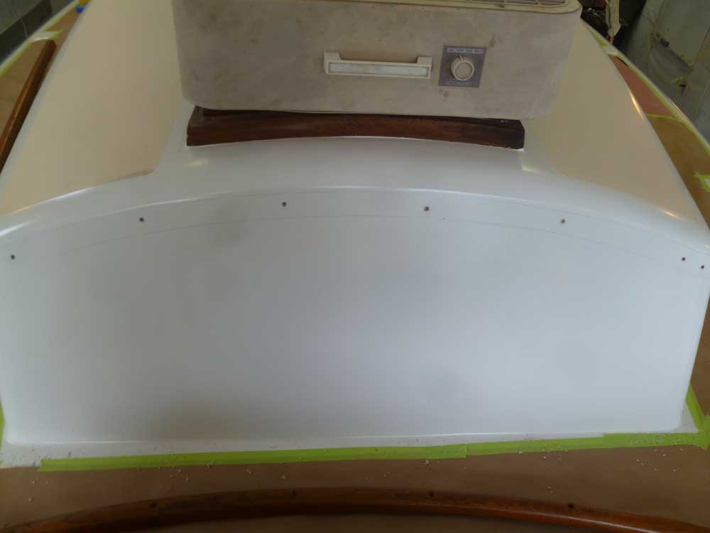
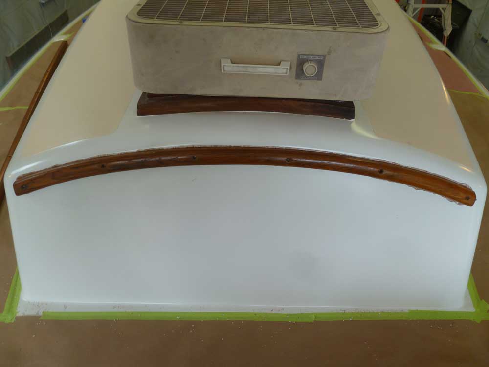
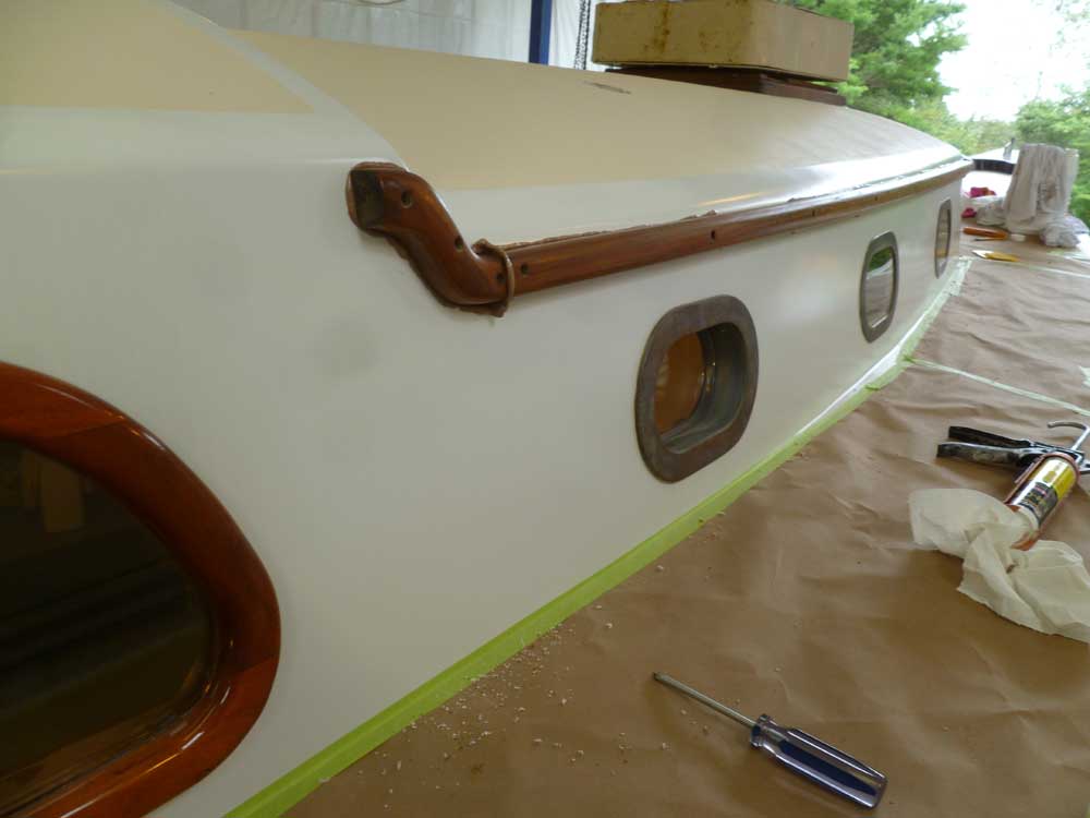
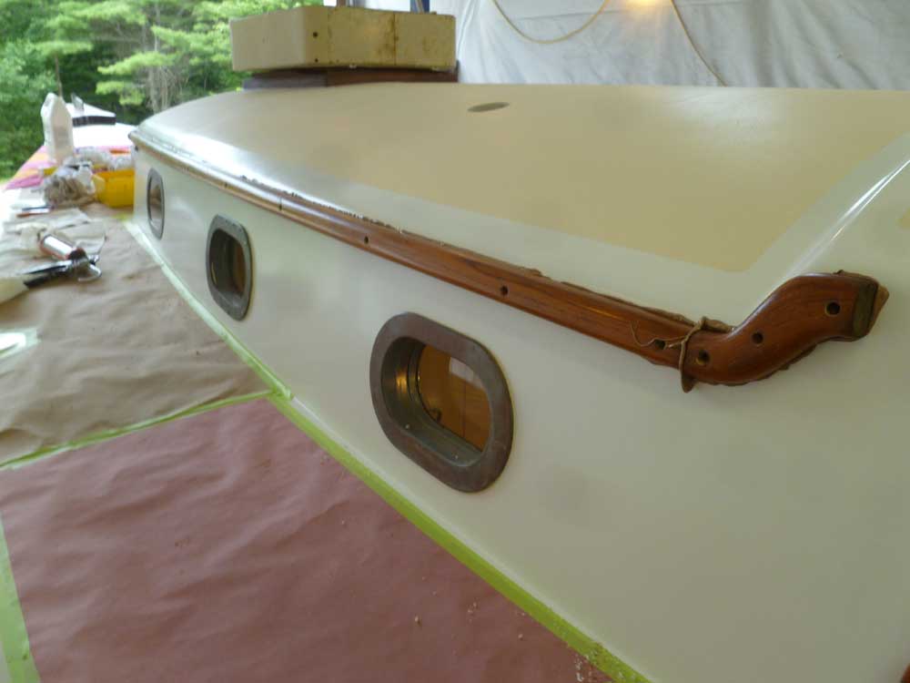
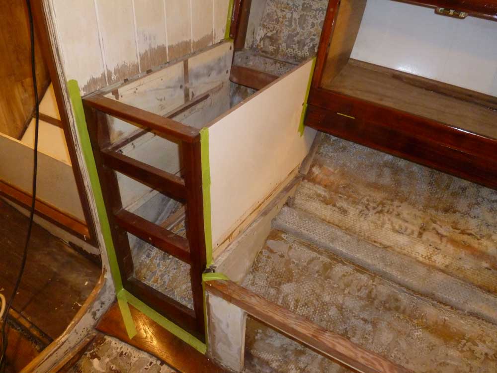
After consulting old photos of the boat--from before I removed the eyebrow--to determine the basic height of the trim, I started at the forward end of the cabin trunk, with the curved forward piece and two corner pieces. These three pieces together would essentially only fit in one location, which would then dictate where the side trim would be mounted.
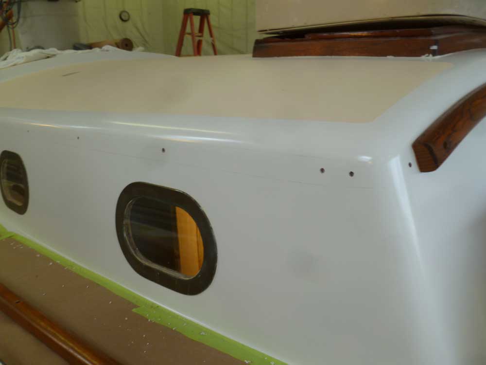
After determining where the forward pieces would go by holding them in place with tape, I test-fit the side pieces to ensure that their alignment looked good in relation to the forward corners.
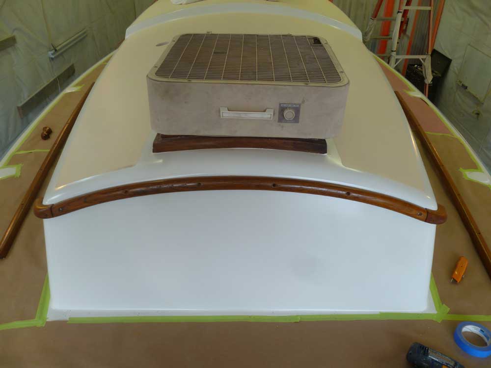
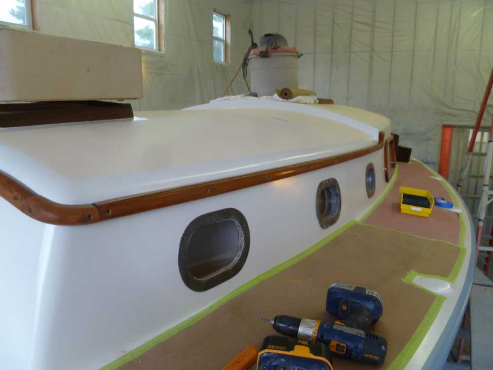
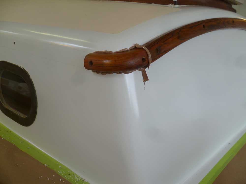
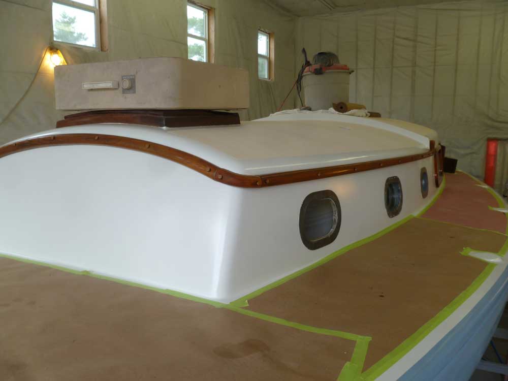
I drilled pilot holes for screws for the forward and corner trim pieces, and secured them dry with screws to hold them in position. Then, I repeated the process with the side pieces plus two additional curved pieces that transitioned the trim up to the higher level of the doghouse above the deadlights. This was where the trim ended for now, as the previous person who'd done the original eyebrow work had not completed the final sections. I'd build these in the near future.
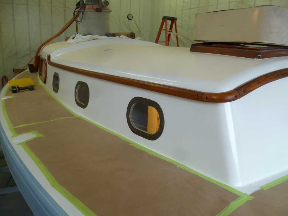
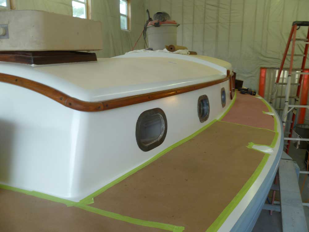
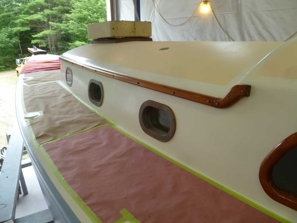
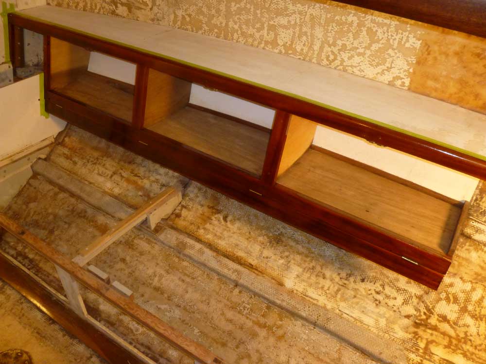
After drilling all the pilot holes, I removed the trim and used a countersink to slightly enlarge the tops of the holes, the better to contain sealant at the screw locations. Then, I applied beads of teak-colored polysulfide sealant, and secured the forward piece in place.
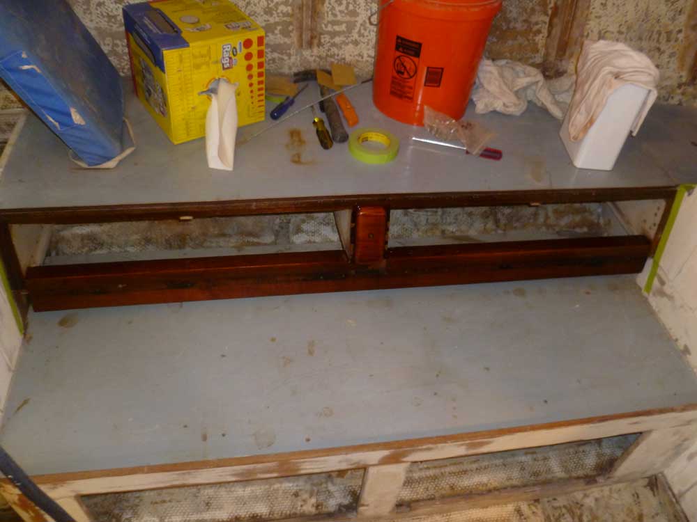
I moved around the starboard corner first, and installed the corner trim, then continued with the long piece down the cabin trunk, and the trim piece at the aft end, using plenty of sealant and securing the rails tightly with screws. Afterwards, I cleaned up the excess sealant.
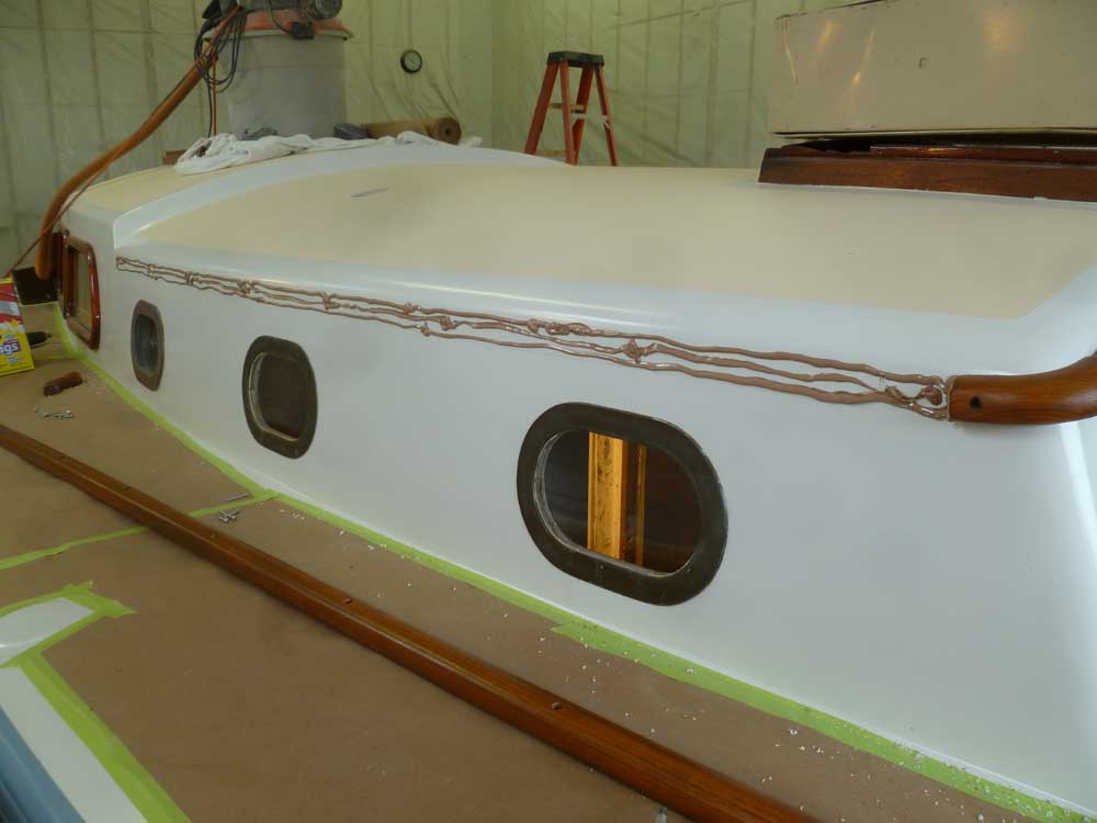
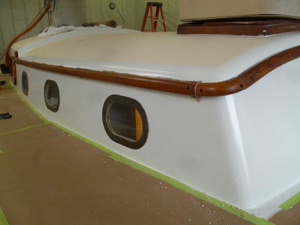
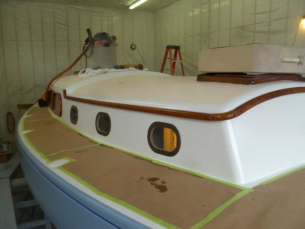
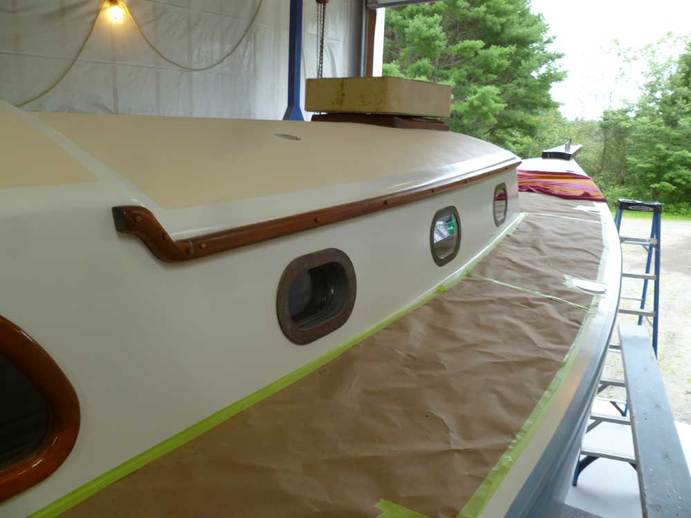
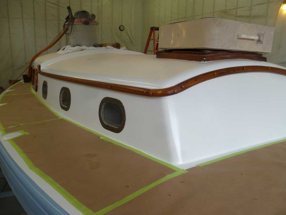
I repeated the process on the port side.
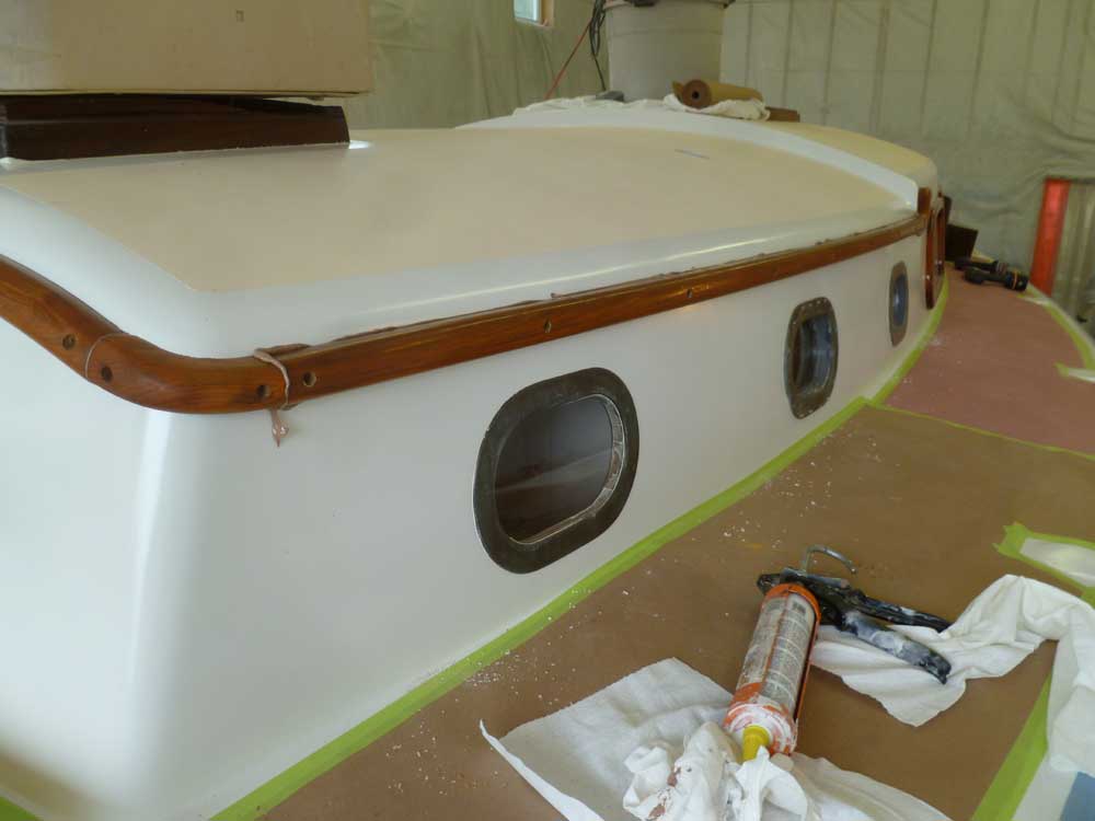
I cut a series of teak bungs at the drill press, then installed the bungs to cover the screw holes in the trim. I left these to cure overnight before paring them off flush.
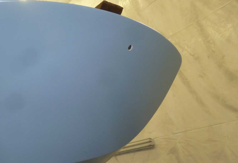
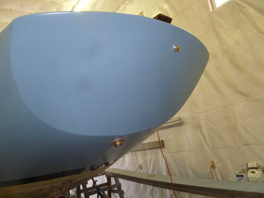
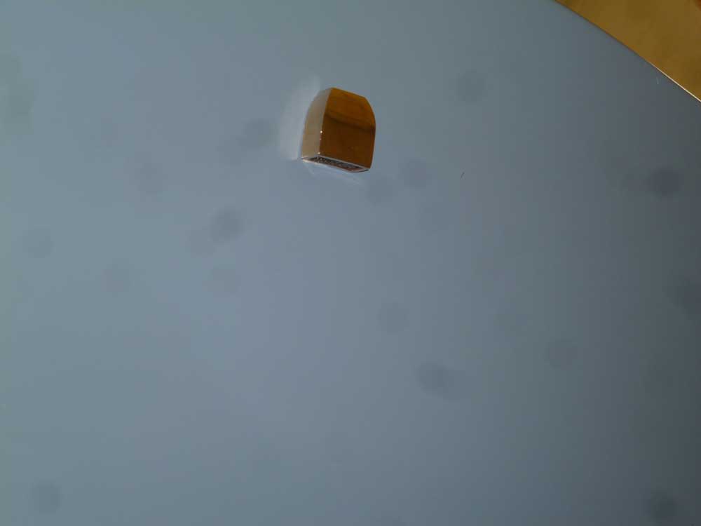
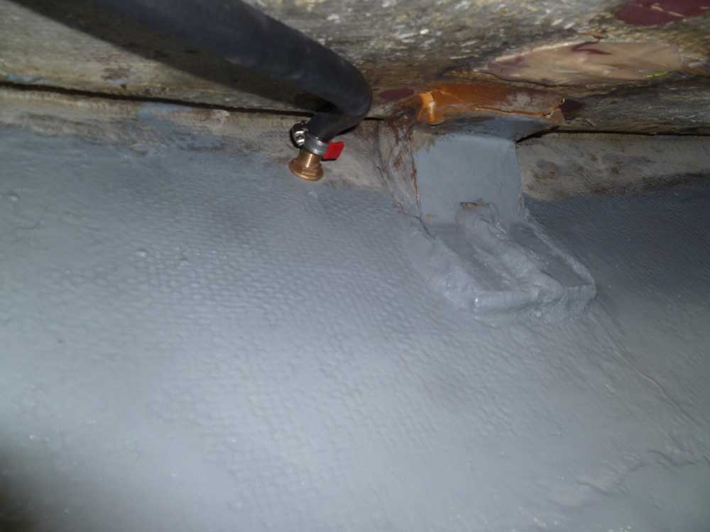
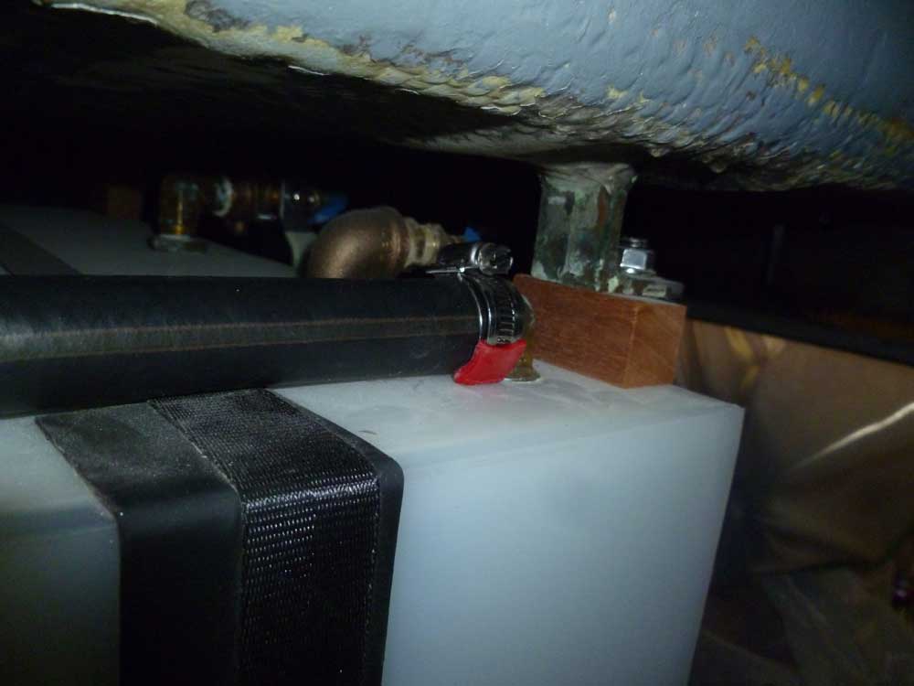
After a few measurements, I determined a location for a new fuel tank vent fitting in the transom. I drilled the hole, then installed the vent with sealant. Inside the boat, I attached a 5/8" vent hose, which I secured along the underside of the deck and eventually ran down to the barbed fitting on the new fuel tank.
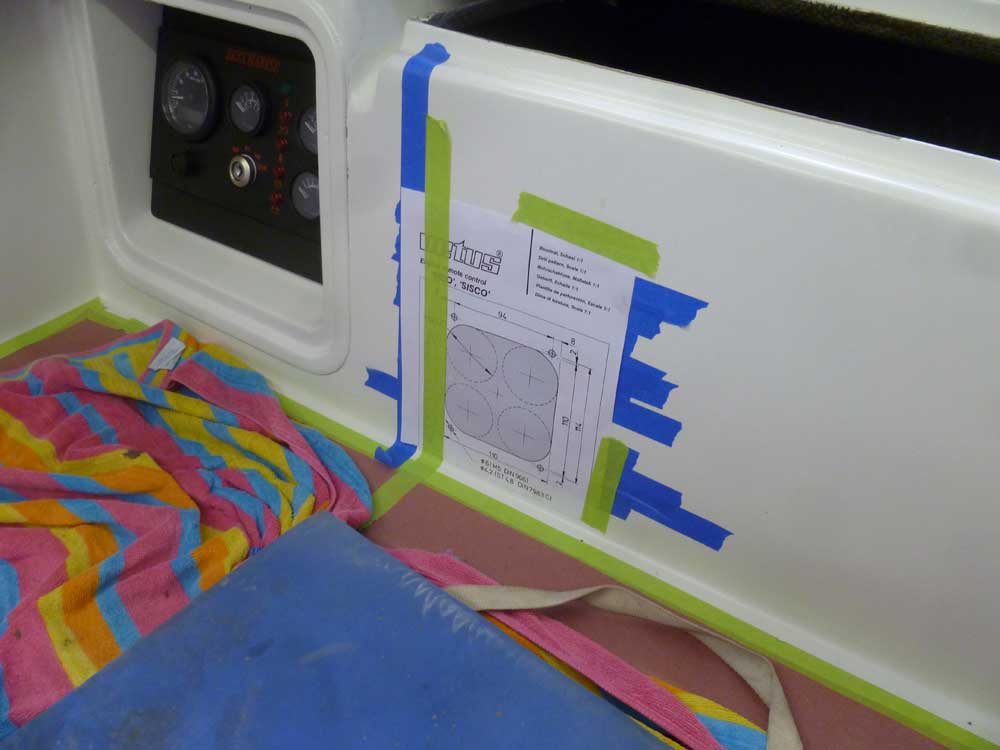
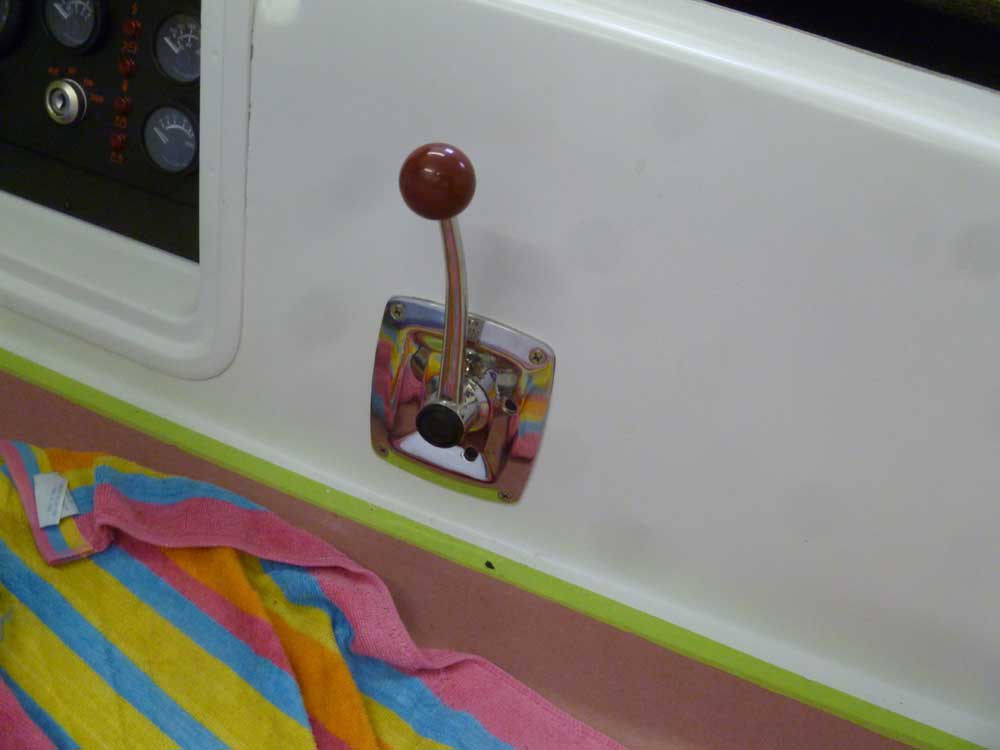
I chose a Vetus SISCO single-lever engine control, and with the new control and cables on hand I prepared for installation. I located the control on the starboard side of the cockpit well, just aft of the engine gauge panel.
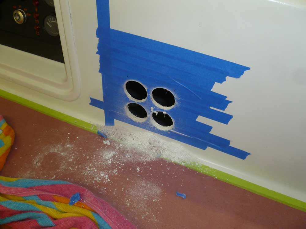
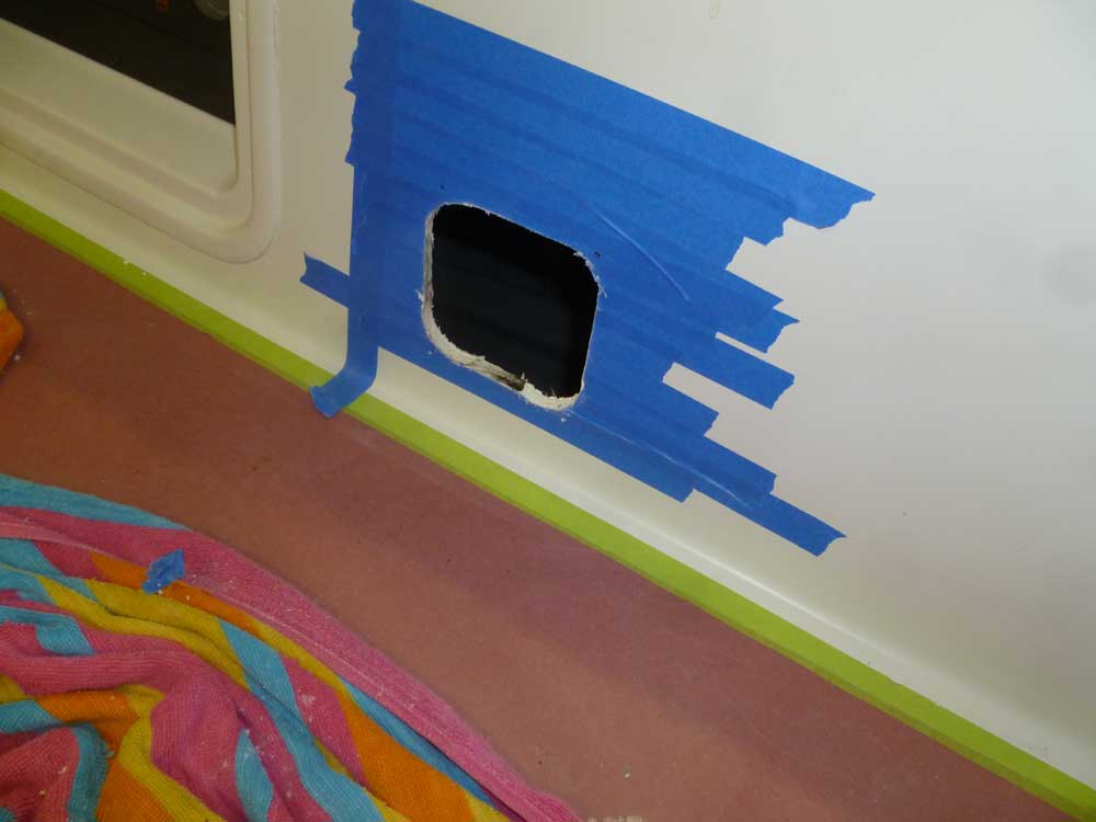
After protecting the area with tape, I secured in place the supplied cutout template, marked the centers of the four 2" holes required for the cutout, and cut out the opening for the control. I used a small saw to remove the material between the holes.
Holding the control in place through the opening, I marked for the four screw holes to secure it, and drilled and tapped for #12 machine screws.
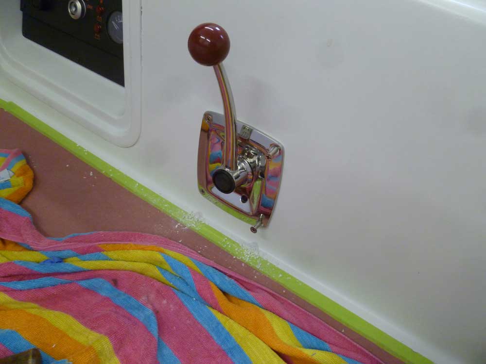
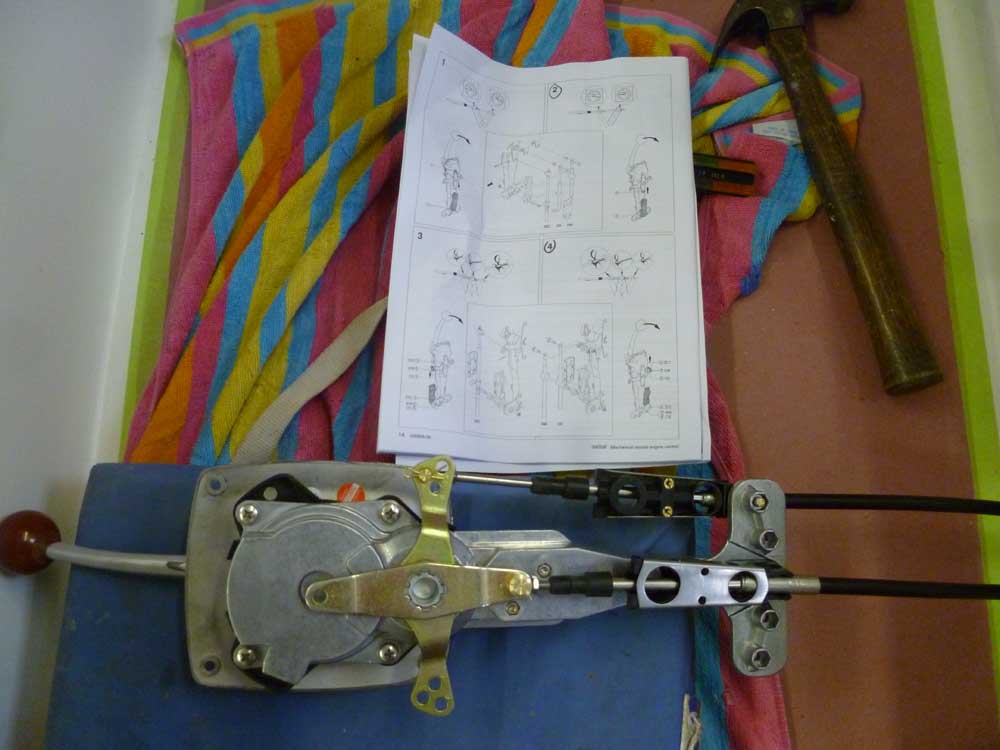
Next, I assembled the various components required to secure the engine control cables to the control. This engine required the throttle cable to "pull" to advance the throttle, and also to "pull" to engage forward gear, so I selected the appropriate mounting locations according to the diagrams and attached the cables as need be before securing the control unit in place against the cockpit well, using the supplied adhesive gasket.
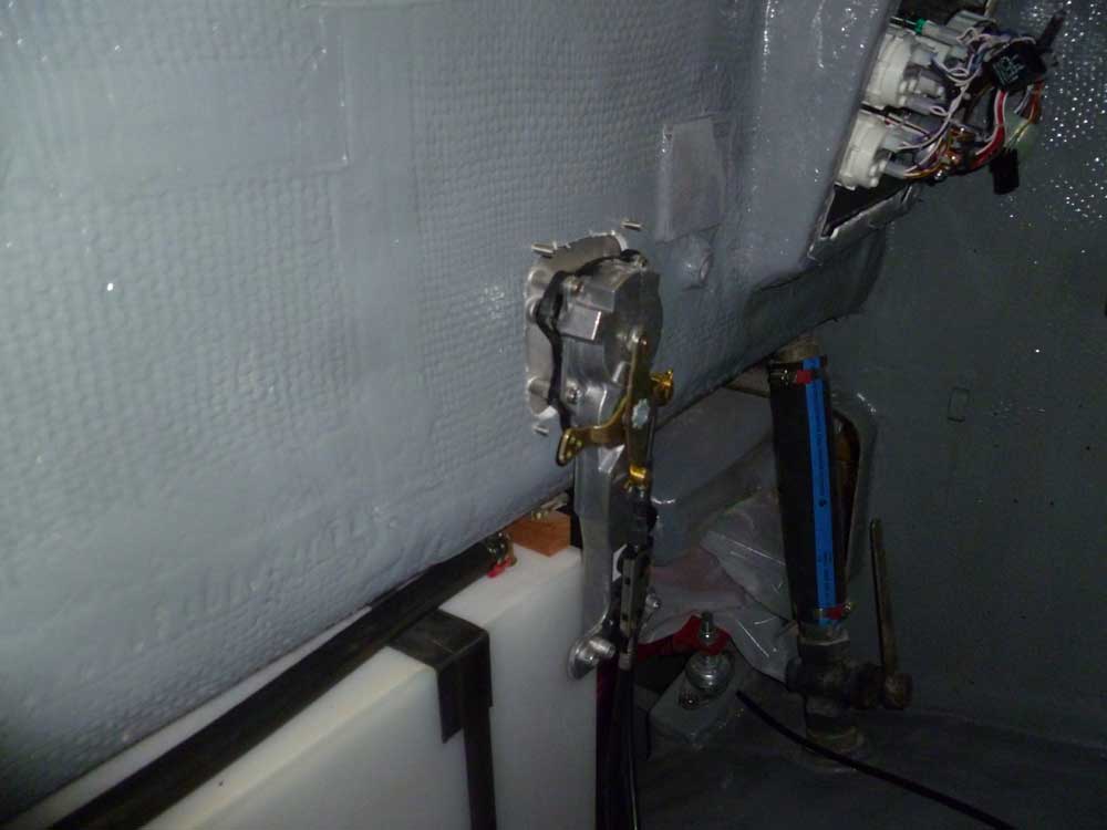
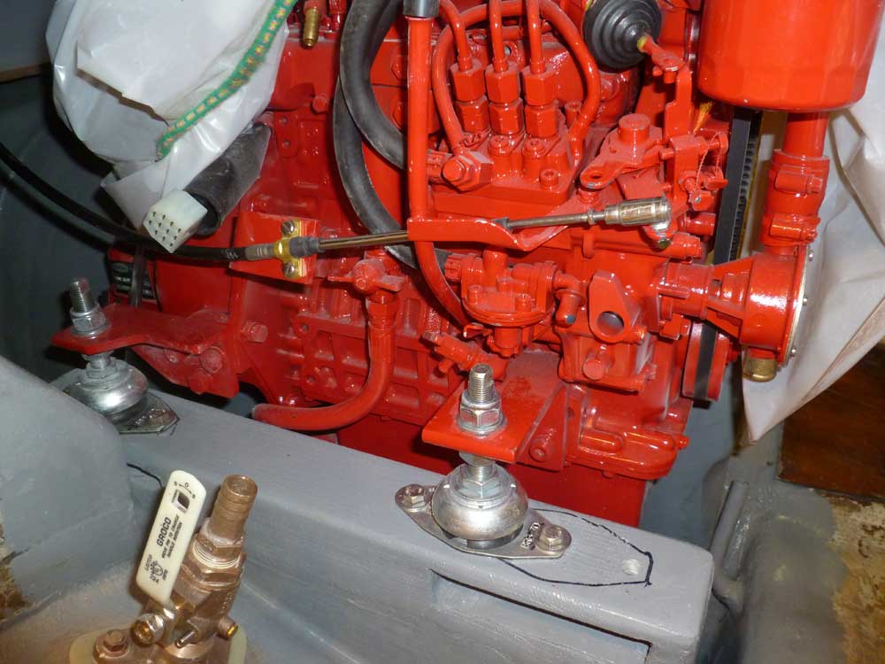
At the engine, I made the connections between the cables and the gear lever on the transmission, and the throttle actuator.
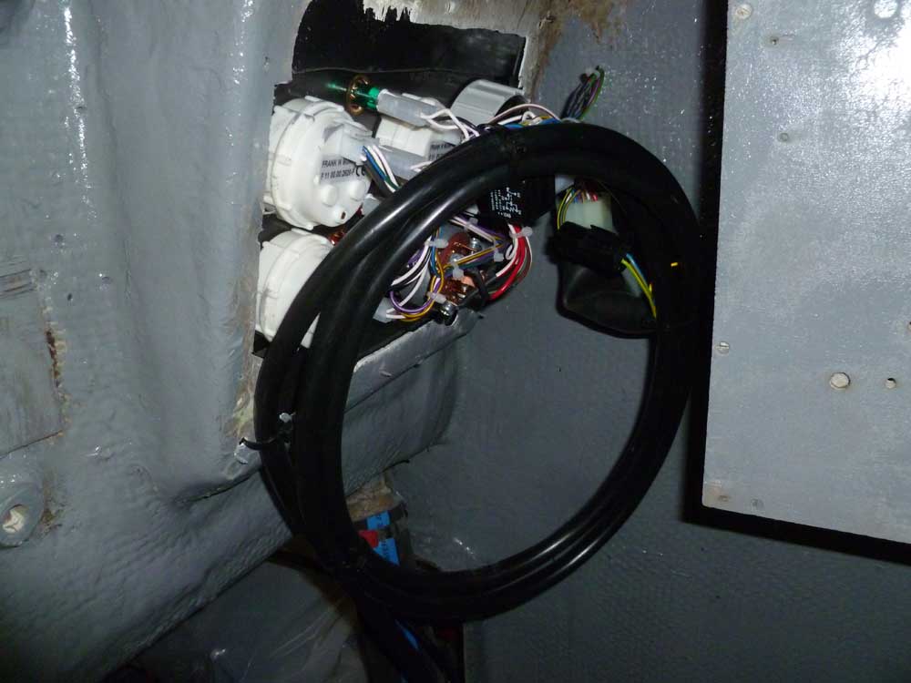
At the same time, I attached and secured the engine wiring harness between the panel and the engine.
Finally, I sanded and varnished again the saloon cabinetry that I'd begun last week.
<Previous | Next>
