110 Cookson Lane | Whitefield, ME 04353 | 207-232-7600 | tim@lackeysailing.com
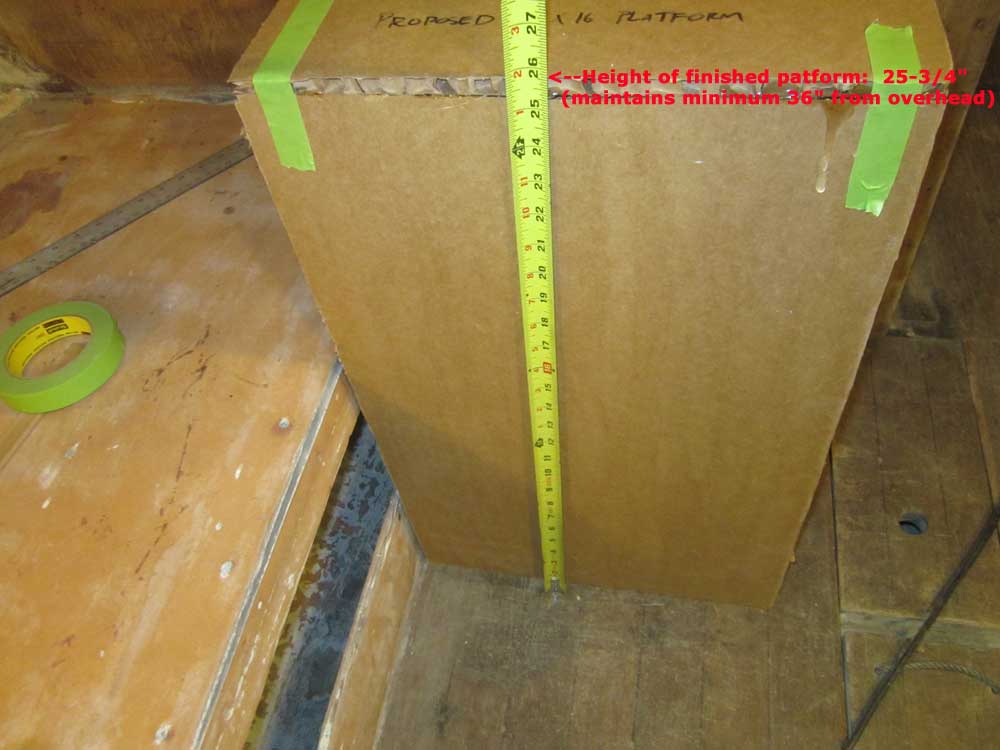
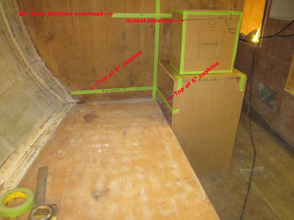
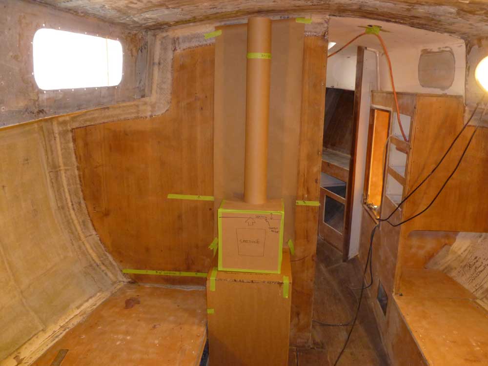
Revisiting the Sardine woodstove installation in greater detail, I started with the basic dimensions of the support cabinet as proposed: a 16" square platform (several inches larger than the base of the stove itself), and approximately 26" from the cabin sole. First things first: I'd mock up the stove and its cabinet, then from there we could determine how, or whether, a table could somehow be incorporated.
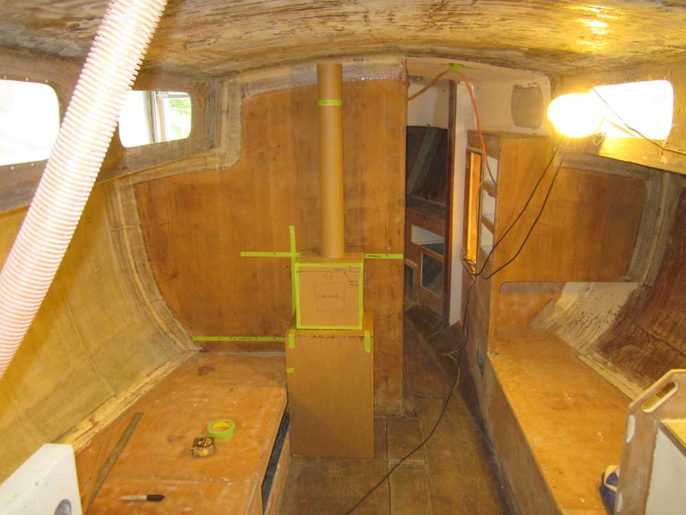
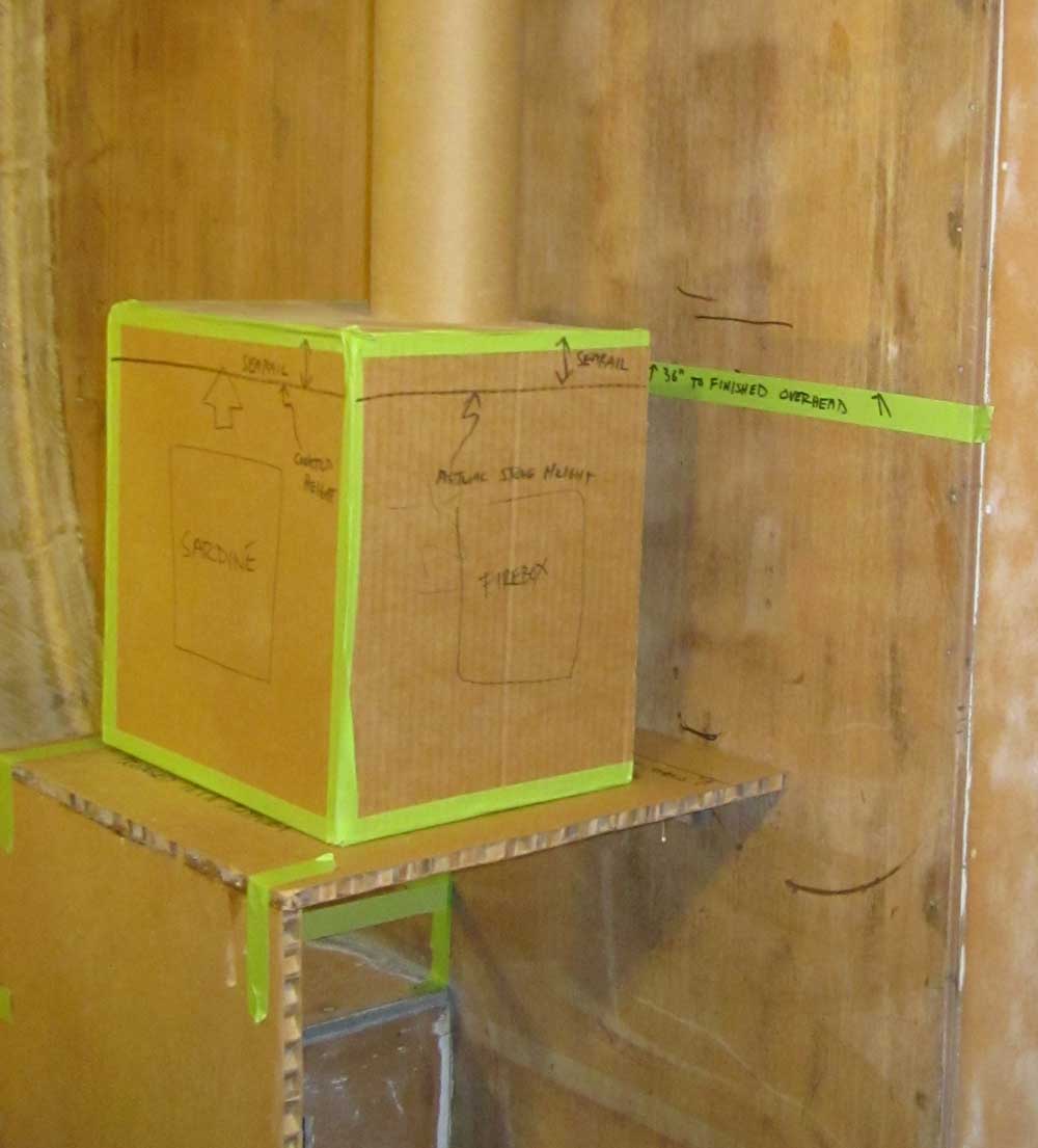
The first major consideration in this installation was my desire to avoid unnecessary heat shielding above the stove. The minimum clearance required above the stove in order to obviate the heat shielding on the overhead was 36, so to begin I made a layout mark at this height, adding approximately one inch to allow for the final position of the finished overhead, and struck a line of green tape horizontally. To project the vertical face of the adjacent berth upwards, i added a vertical strip of tape to aid in alignment of the platform.

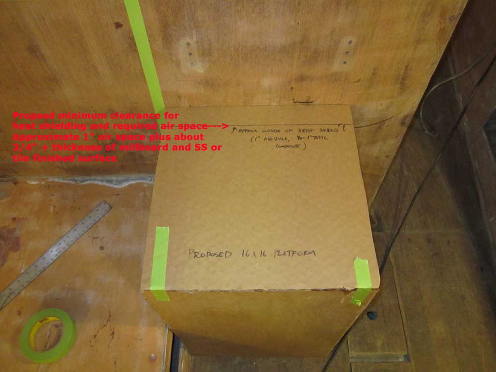
The size and location of this cabinet, which, if built, would be fully enclosed and incorporate firewood and general storage beneath, was set well in from the corner of the bulkhead and allowed good access to existing bilge hatches and the passageway forward.
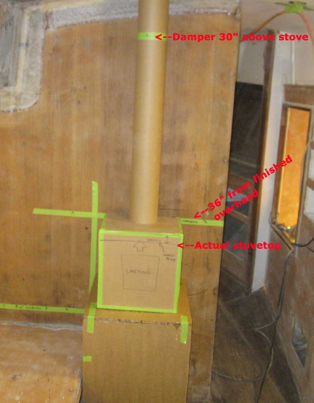
The cardboard mockup of the stove I made earlier incorporated into its overall shape the height of the SS searail included with the stove, which stood about one inch proud of the actual stovetop. To more accurately determine the final positioning of the stove and any heat shielding, I made a mark on the cardboard to simulate the actual height of the stovetop, 1" or so below the top of the mockup.
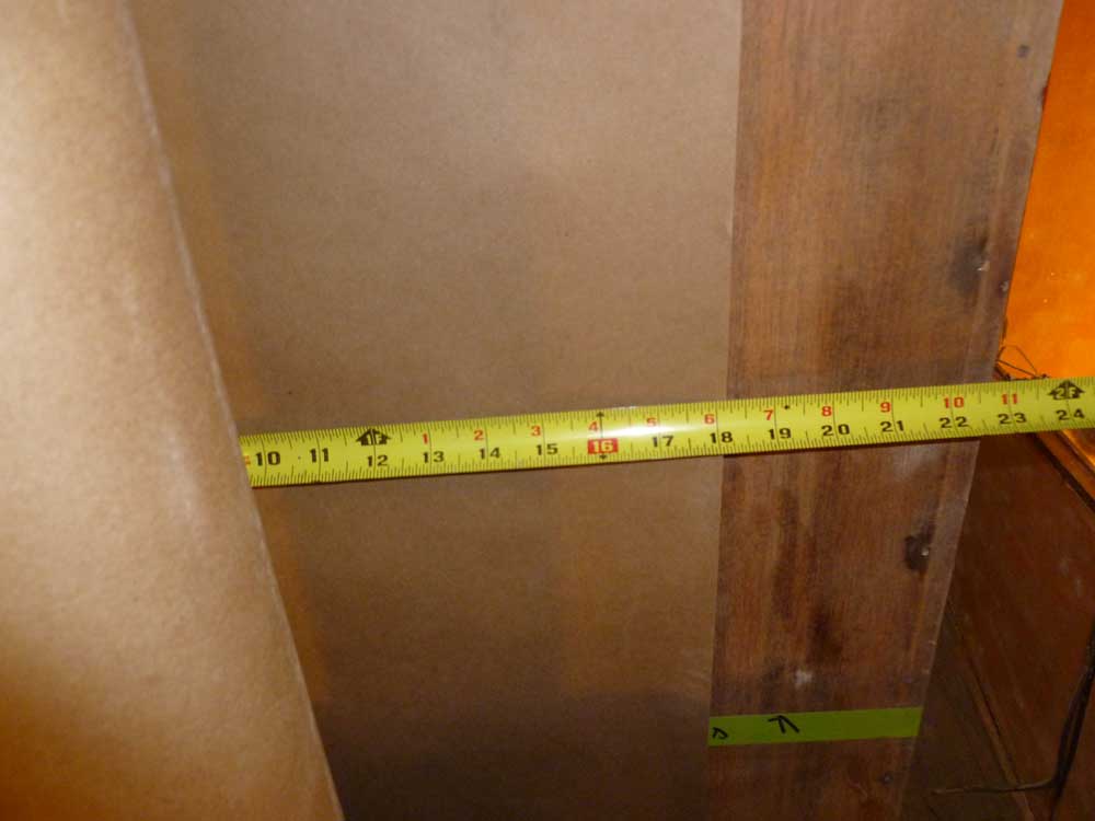
I made a mark on the platform about 2" from the bulkhead to signify the rough clearance required for the heat shielding: a 1" air space plus approximately 3/4" total thickness composite of heat-resistant millboard and appropriate stainless steel sheeting (or other) over the outside, plus a little leeway. Then, I placed the "stove" on the new platform roughly in what could be its final position.
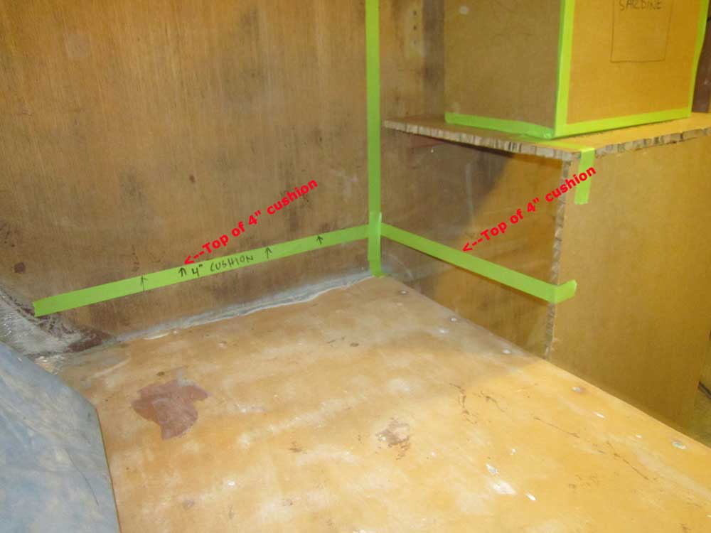
I made additional tape marks above the adjacent berth to simulate the eventual finished height with cushions (4") installed. This left 6" or more between the cushion and the stove support platform.
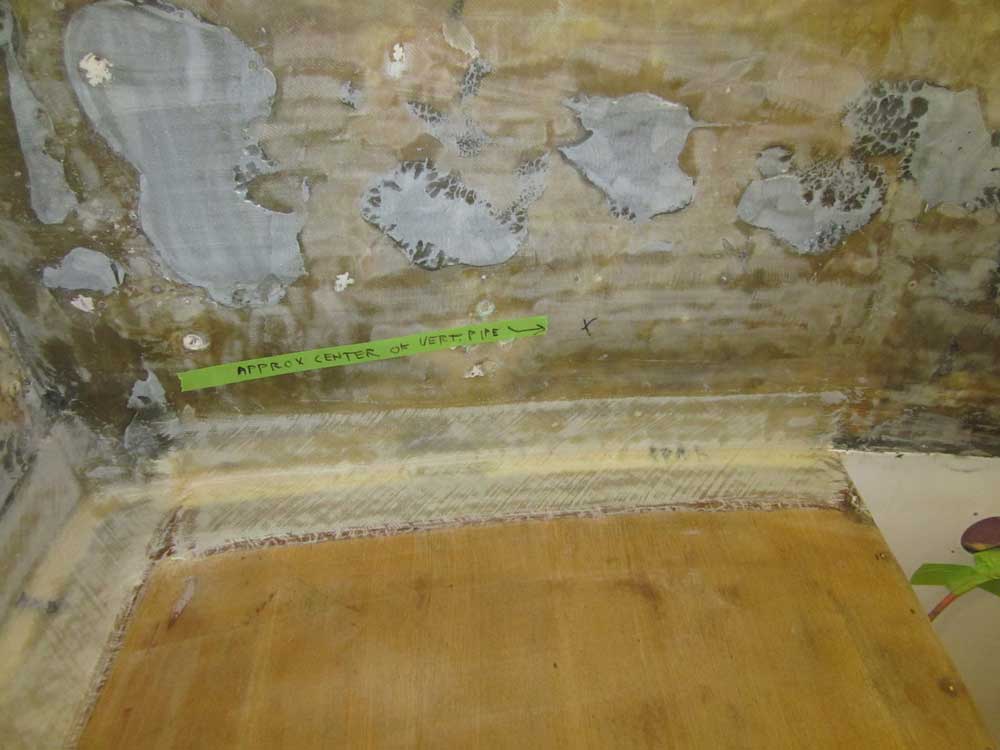
Next, I simulated a vertical length of 4" stovepipe from a paper cylinder. The stove required a damper approximately 30" from the stovetop, so I marked this with green tape to show this location. Then, I made a mark on the overhead in the center of the 4" pipe for future reference.
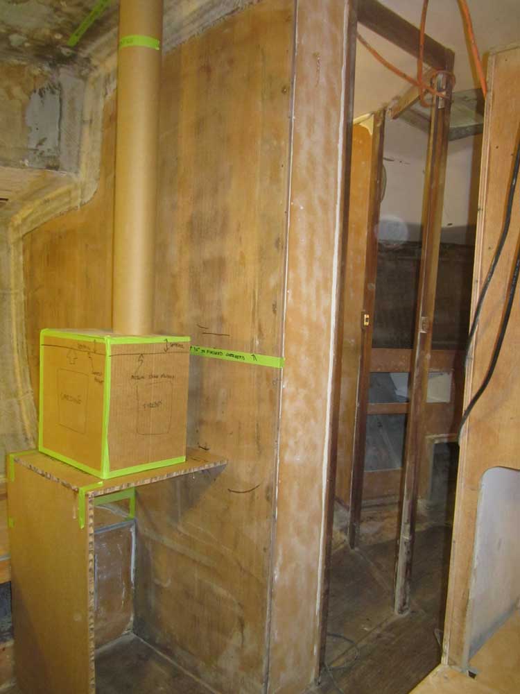
A vertical smoke pipe seemed most desirable for its simplicity and better appearance, but I wasn't yet sure whether or not any angles would be required. We could add up to two 90° angles if needed, though at most this installation might require two 45° bends to force the exhaust outlet further outboard if needed.
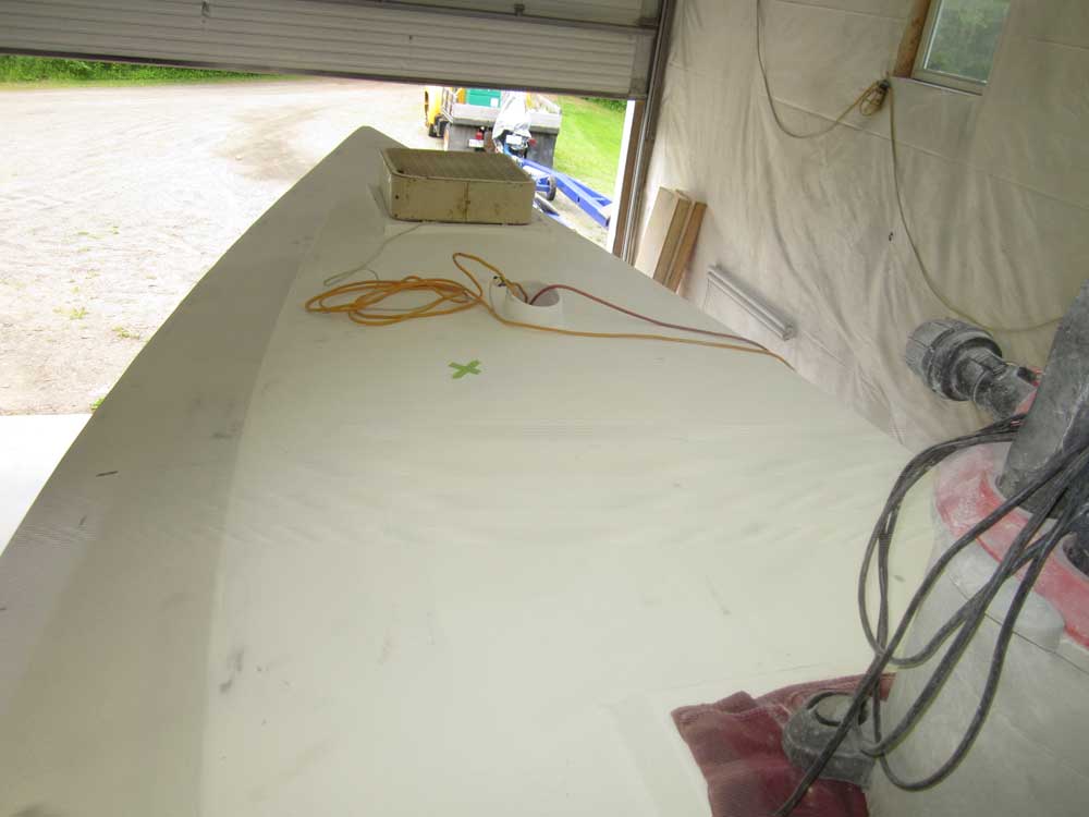
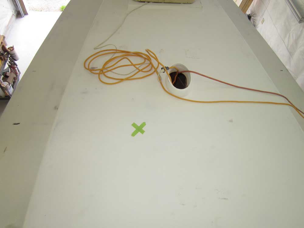
The mast was located just forward of the main bulkhead, close by to the stove, so my main concern at this point with the exhaust was suitable clearance from the mast, boom, boom vang, or other obstructions. Inside the boat I made a few measurements to the center of the stove pipe, then transferred them up on deck and made an X mark in the approximate location.
Ongoing questions/concerns at this point in the process:
1. How far on either side of the stovepipe, and the stove itself, need the heat shielding run?
2. Does using a double-wall exhaust pipe eliminate the need for heat shielding behind the stove pipe, as well as the need for a protective grate on the other side of the pipe to prevent unwanted contact?
3. How much vertical clearance abovedeck will the Charley Noble (exhaust stack) require? In its location as seen above, will this pose problems with the boom, boom vang, sails, sailcover, or nearby running rigging?
4. Approximate height of an appropriate table would be around 30" from the cabin sole, or 4-5" higher than the top of the stove platform. Any sort of permanent mount using the stove platform as its base could create a need for additional heat shielding and, worse, hide the Sardine from view and placing it in a "nook". There's more work to do figuring out the best approach for the table, but I think the stove is more important overall and should take precedence at this stage. More to come on this.
After receiving additional information from Navigator Stove Works, builder of the Sardine, I was able to mock up the exhaust stack and heat shielding requirements as suggested by NSW.
To begin, I made up a simulated Charley Noble from paper, rising approximately 10" from deck. The mockup shown is just a bit taller than this, as I added the cone shape for fun after cutting the "pipe" to 10". This represented the minimum height of the finished stack, with the smallest available smoke head installed directly on the deck iron.
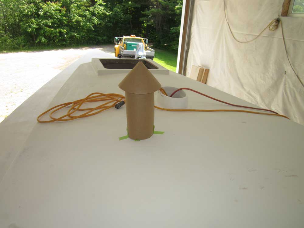
With the smoke head removed during normal sailing usage, there'd be virtually no protrusion above deck. At anchor or dock, this location would probably be safe for use, but I suppose heavy usage could, over time, cause smoke staining to the mainsail or cover. This probably isn't enough reason on its own to offset the smoke pipe, though this could easily be done depending on aesthetic concerns belowdecks.
NSW eschewed the notion of double-wall pipe and protective grating over the exhaust pipe inside the boat, which worked for me.
NSW suggested a minimum 18" x 18" square of heat shielding behind the stove itself, with additional 18" shielding behind the smoke pipe (9" on either side of center). Therefore, in this case this meant an 18" strip extending from the stove platform all the way to the overhead.
From brown paper, I made up a simulated section of heat shielding to show how this might, at its minimum, look.
Another option from NSW would be to use half-round SS shielding attached directly to the exhaust stack, like this.