| Kaholee Refit |
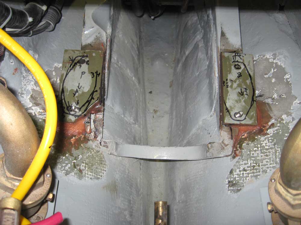
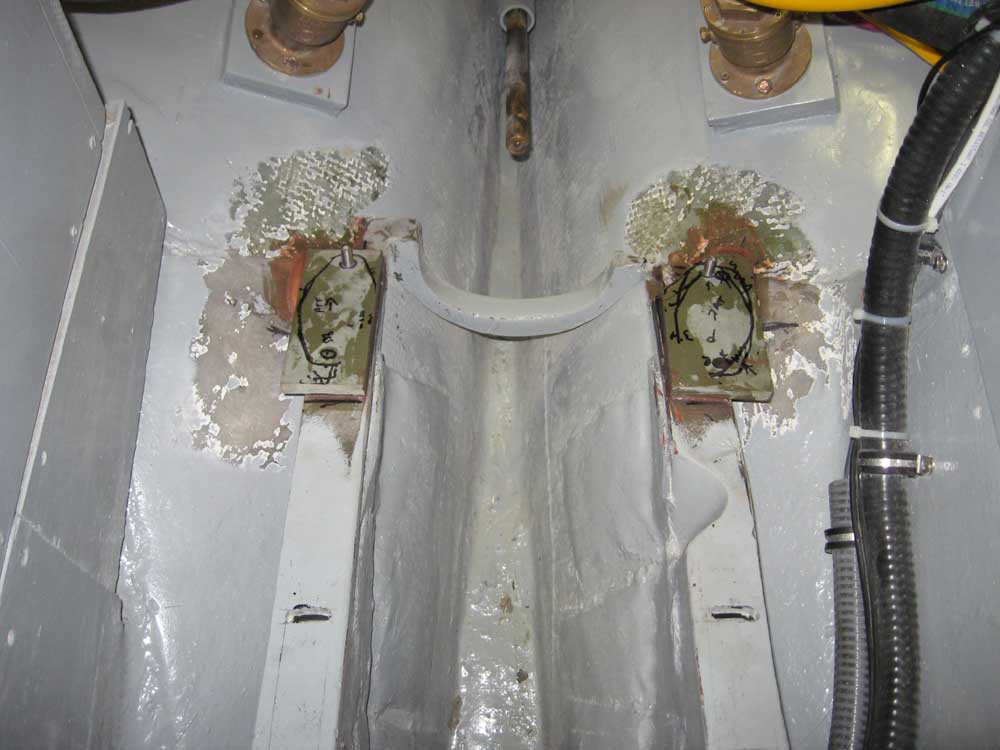
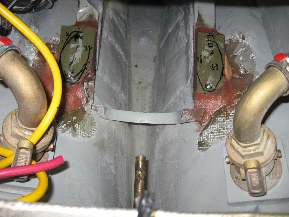
October 23, 2007 I spent the morning working on the engine foundations. Note that I didn't have a camera on hand much of the morning, but my new replacement (Canon A560, next gen in a string of similar Canon utility cameras that I have owned and abused happily and satisfactorily through the years of projects) arrived around lunchtime--by which time the mount modifications were in place and secured. The photos below begin at that point. I began by milling some 1/2" prefab fiberglass panels into two rectangles of appropriate size to support the aft mounts on the engine. Initially, I cut both pieces the same size, but after my initial test fit with the engine I trimmed then each somewhat, and asymmetrically from side to side to suit the situation at hand. Specifically, the port side required a wider piece than the starboard, since the way the mounts were the port side overhung the pre-existing foundation more. Earlier, I had determined that the additional 1/2" of height was actually a helpful thing in order to better bring the engine into rough alignment with the shaft center. Because I didn't trust my engine template (which, to reiterate, was built according to Beta Marine's own drawings of this engine and mounting system, but which didn't correspond to the actual engine as shipped), each test-fit of the new mount supports required that I move the engine in and out of place in the engine room, although I found that I could raise only the aft end of the engine if I temporarily secured the forward end with bolts. This made life a bit easier, since all the work was concentrated on the after mounts. During this process, I also determined that the cuts I made to the old foundation would allow the proper clearance for the transmission lever. Over a series of test fits, I fine-tuned the shape and position of the new pads and the aft mounts. For rough alignment purposes, I used an old propeller shaft through the stern tube, this only to approximate the desired position of the engine from side to side. (Final alignment, of course, will come much later in the process after the new shaft has been fabricated and attached to the coupling.) Eventually, I located the engine and the mounts where I wanted them, and made alignment marks on the fiberglass pads so that I could easily locate them during the adhesion process. I also marked for the fastener holes on the mounts. With the engine pulled back out of the engine room one (hopefully) last time, I removed the fiberglass pads and drilled and tapped holes for the aftermost bolt locations. From the underside of the mount, I milled countersinks, and then installed 3/8-16 x 1-1/4" flathead machine screws from beneath into the tapped holes to create permanent studs, since there really wasn't practicable room to secure a nut and bolt at these locations thanks to the curvature of the hull. To permanently install the new pads, I mixed a batch of thick epoxy and silica, and used it to secure the pads to the existing flanges and to the adjacent hull as allowed. For now, I wanted to mainly tack the pads in place so they wouldn't move; later, I planned to add additional epoxy fillets to further secure the pads. I aligned the pads to my locator marks and, being careful to keep the epoxy away from the threads on the two studs, secured them in place. I left these to cure for a while before continuing. |
|
|
After lunch, the initial application of epoxy had cured sufficiently to allow me to apply a second coat, mucht he same as the first, although I formed healthy fillets wherever I could reach, including beneath the pads and along the bottom edge of the original foundations' flanges (being careful to leave the forward bolt location free of excess epoxy. I should note here that I considered extensively whether I should apply fiberglass cloth over these new pads and onto the hull or old foundation. Eventually, I determined that this was unnecessary and would be less than ideal in this situation:
These new additions aren't going anywhere, even without fiberglass over the top. At this point, I had to wait for the epoxy to fully cure before I could continue with the engine installation, so I moved on to several other tasks. |
|
|
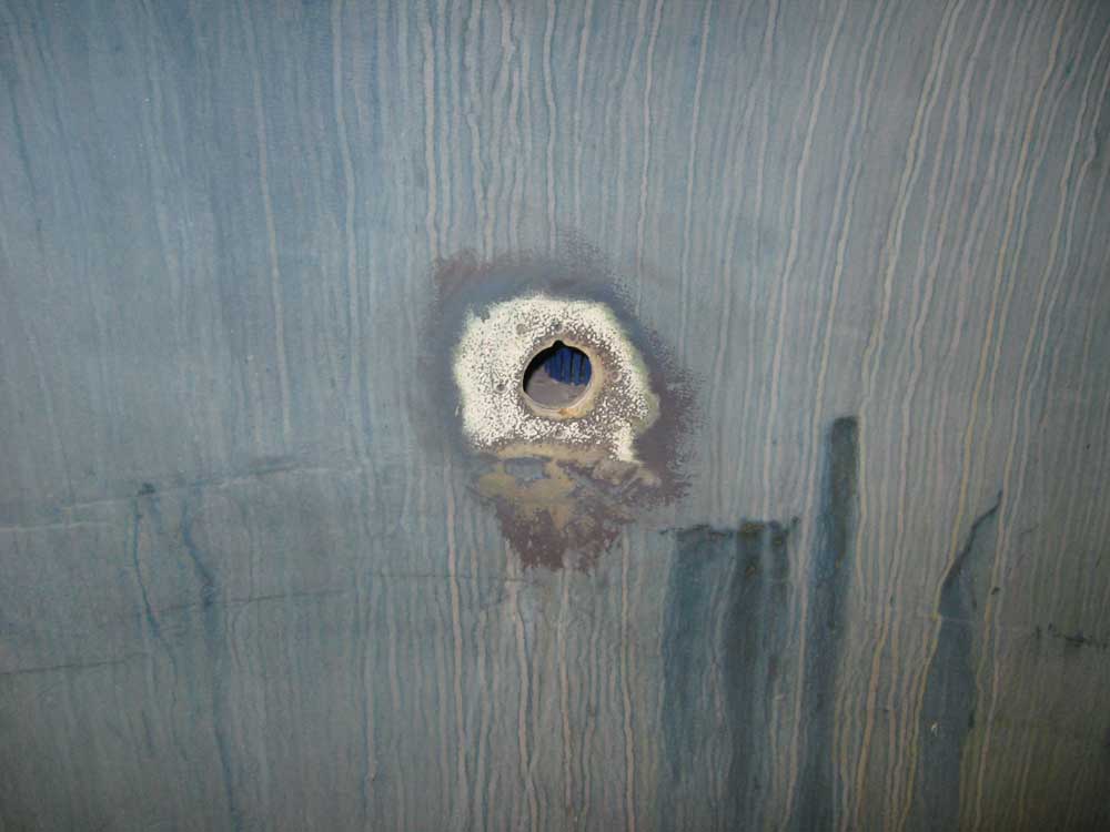
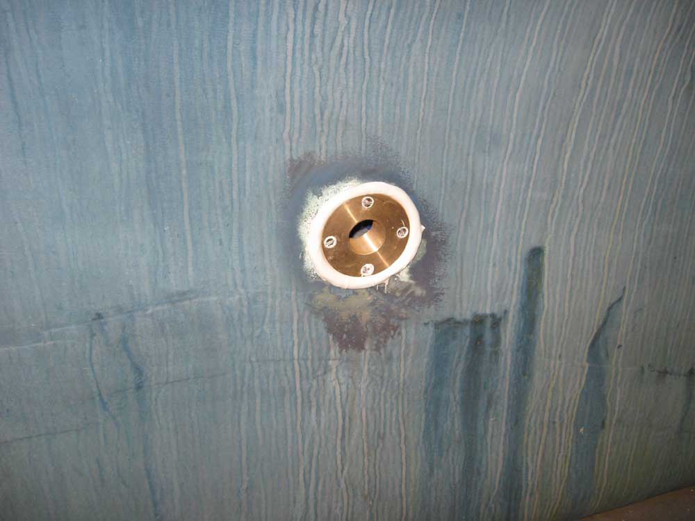
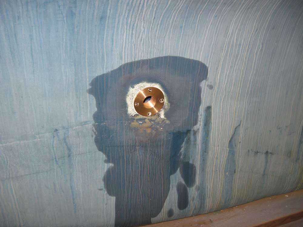
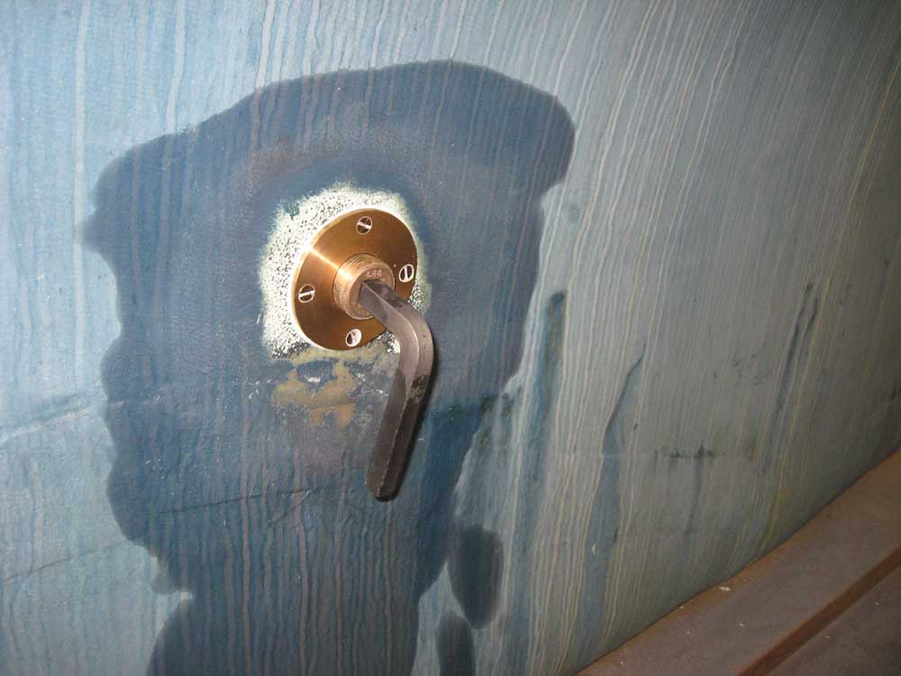
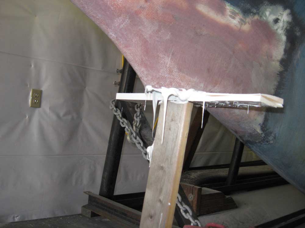
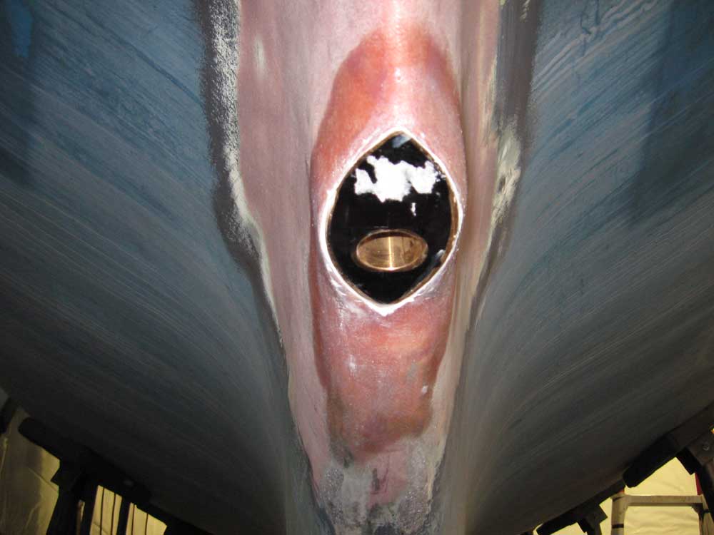
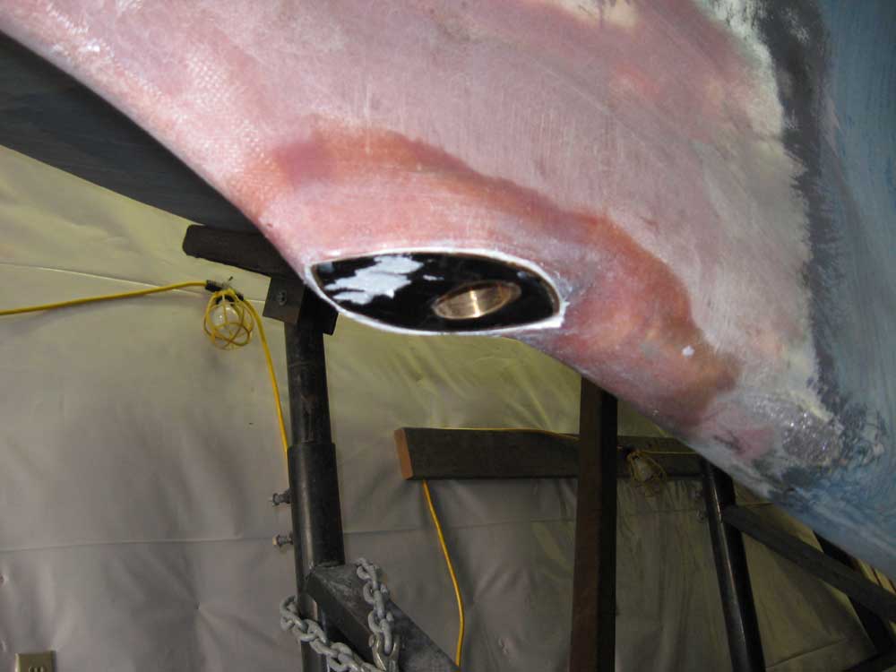
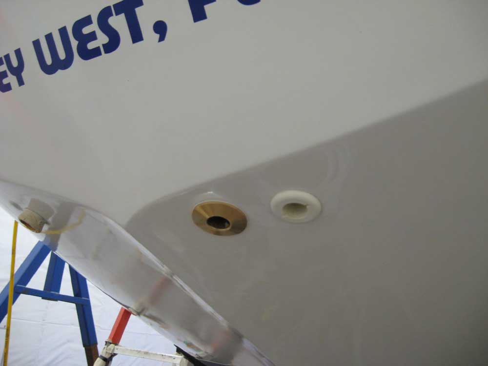
I had been saving up several installations until I could justify opening a tube of 4200 polyurethane sealant (since the polyurethanes don't last long in the tube once they've been opened). Now was the time. I had several things to install where I wanted the additional strength of the 4200: the depthsounder transducer; a garboard drain plug; and a new through hull in the counter for the galley sink drain. (I also had a garboard drain to install in my own boat.) I began with the garboard drain. Last spring, before I moved the boat outdoors for storage after Phase I, I drilled a 1/2" hole in the hull near the bottom of the bilge to allow any rainwater to freely exit, since there was no electrical system nor bilge pumps at that time. At some point we decided to make the drain location permanent, and obtained a bronze garboard drain for the purpose. To install the drain, I drilled a 1-5/8" hole with a hole saw, and milled a small recess at the top edge to provide clearance for a cast keyway on the garboard drain. Then, I drilled and tapped for the four fasteners required to secure the casting, using #10-32 bronze fasteners. I ordinarily would have chosen 10-24 fasteners, but the fine threads were all I had in stock. I chose machine screws rather than self-tappers because threaded, tapped fasteners are stronger, cause less (or no) damage to fiberglass laminate, and are more inherently watertight. I finished the simple prepwork by removing the bottom paint from the bonding surface, which may or may not be necessary. I installed the fitting in a heavy bed of 4200 sealant; I cleaned off the excess and was done. |
|
|
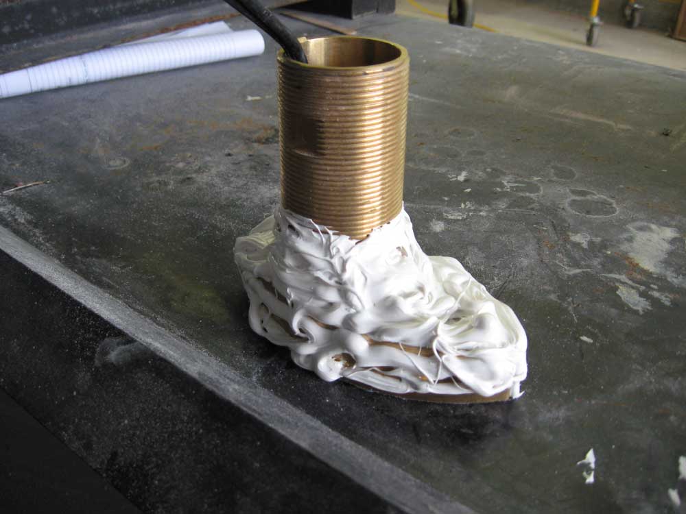
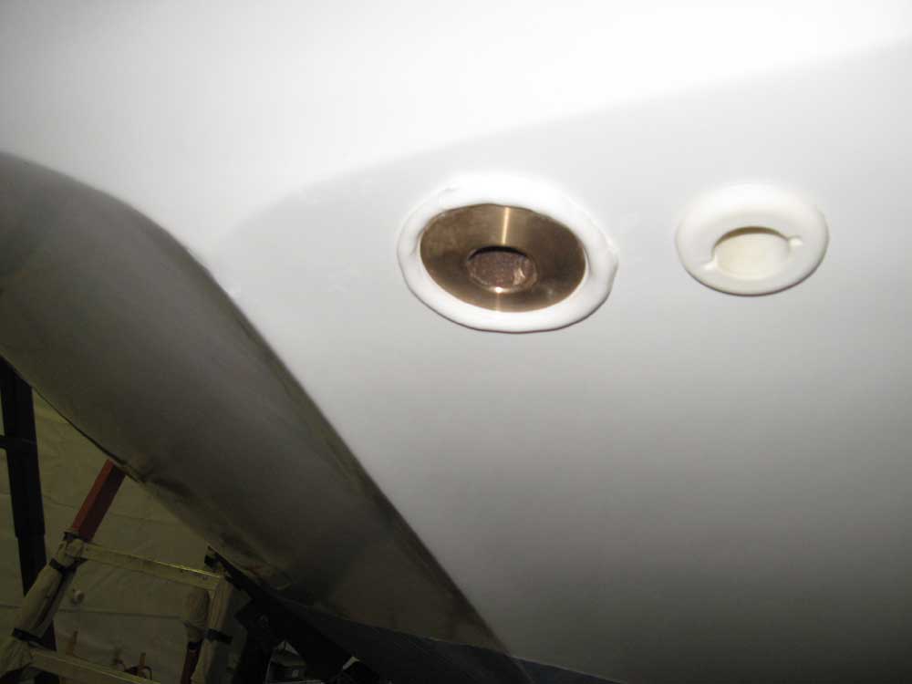
I covered the bottom surface of the transducer with tape for protection, and installed the fitting in its molded fairing with lots of 4200 sealant, particularly on the top edge and the base portion of the threaded neck. I also applied sealant around the vertical edges of the transducer to fill the small void between it and the fiberglass fairing. To push the unit tightly into position and force the sealant to spread, I wedged a piece of scrap beneath it, with a scrap of UHMW plastic at the top to protect the transducer. I secured the nut within, and cleaned up the excess sealant, taking care not to use any solvent (paint thinner, in this case) on the face of the transducer. (The white stuff on the transducer is the remains of the adhesive label stuck there by the manufacturer, admonishing that no solvents touch the surface. They don't say how one is supposed to remove the adhesive left behind by the warning label.) |
|
|
Next, I installed a 1" through hull for hose at the counter, for the galley sink sump drain. I bedded this in more of the 4200; it was such a simple installation that I have little to say about it. |
|
|
I worked on a few smaller, non-noteworthy projects during the afternoon, including building a simple backing block to support the swing-away bracket for the soon-to-be-installed Raymarine chartplotter and display unit, and also installing a plug in the opening on the engine where the ill-fated petcock had been. This plug is a bit higher-profile than I had hoped for, but my initial choice--a shorter plug with Allen wrench head--turned out to be impossible to reach with an Allen wrench for tightening, thanks to the mind-boggling placement of the mounting flange: the gift that keeps on giving. This plug is nickel-plated brass with a hex head that is at least sort of accessible for tightening within the confines of this space. |
|
|
|
|
|