| Kaholee Refit |
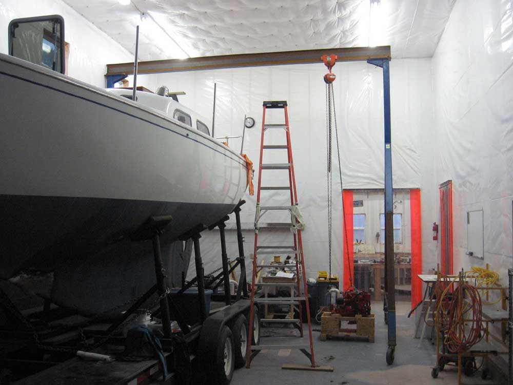
October 19, 2007 I spent most of the day working on the engine. I had hoped to progress to the point where I had the engine bolted in place today, but it was simply not to be; issue after issue arose as I got into the process. Some of these issues were to be expected; others I found unforgivable. No one ever said (at least not with a straight face) that any engine could be dropped in without a few clearance issues, and I wasn't expecting the process to be trouble free, but some of the things I discovered left me shaking my head in bewilderment (or at least that's all I can say on this "family" website). I'll document all these issues in due course. To get started, I moved the crated engine into the shop bay and placed it near the gantry crane, which I had positioned yesterday. |
|
|
During yesterday's initial engine inspection, I noted that the bolts securing the after mounts seemed further apart than I was expecting. Back in February, I had used Beta Marine's own drawings of this engine in order to construct a template and determine how well the new engine would fit in the existing engine compartment and using the existing beds that had been in place for the Atomic 4. At that time, I determined that the A4 mounting centers as indicated on the Beta drawing were 11.5" front and 11-5/8" rear. This tied in fairly well with the existing foundation. But my initial rough measurement yesterday seemed to indicate that the after mounting centers were, in fact, somewhat different than anticipated. At first, I attributed this to the fact that the bolts securing the flanges to the shipping crate were smaller in diameter than the holes, and therefore located further apart than the actual centers. I removed the nuts on one side to confirm this. While this was in fact the case, I discovered this morning when I unbolted both sides that the after mounting centers were not 11-5/8", but were actually 12". This 3/8" discrepancy represented a huge error in either the flanges' construction or the installation drawing, and I was less than pleased with this discovery; immediately, I knew that it would through a significant wrench into the installation works, though at this point I had to reserve judgment until I could mock up the template with the flexible mounts, which I did at this point. With the mounts positioned on the template according to the actual engine's measurements, instead of just the drawing, it looked like the forward mounts would be OK (the forward mounting centers on the engine were identical to the measurements on the drawing), while the after mounts seemed a bit wide (not unsurprisingly). Because of the awkward rectangular shape of the template, I was unsure of exactly how well the after mounts would eventually fit, so I decided I'd have to see how the engine itself actually fit. At least I was able to determine a rough height adjustment for all four mounts before I installed them on the engine flanges. |
|
|
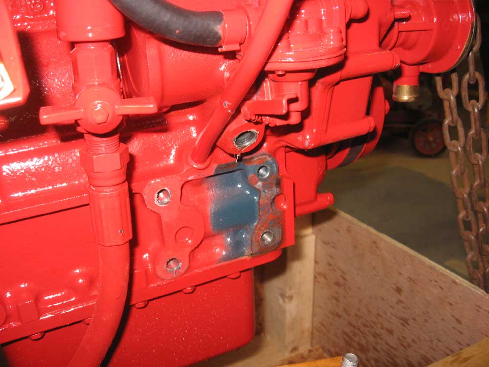
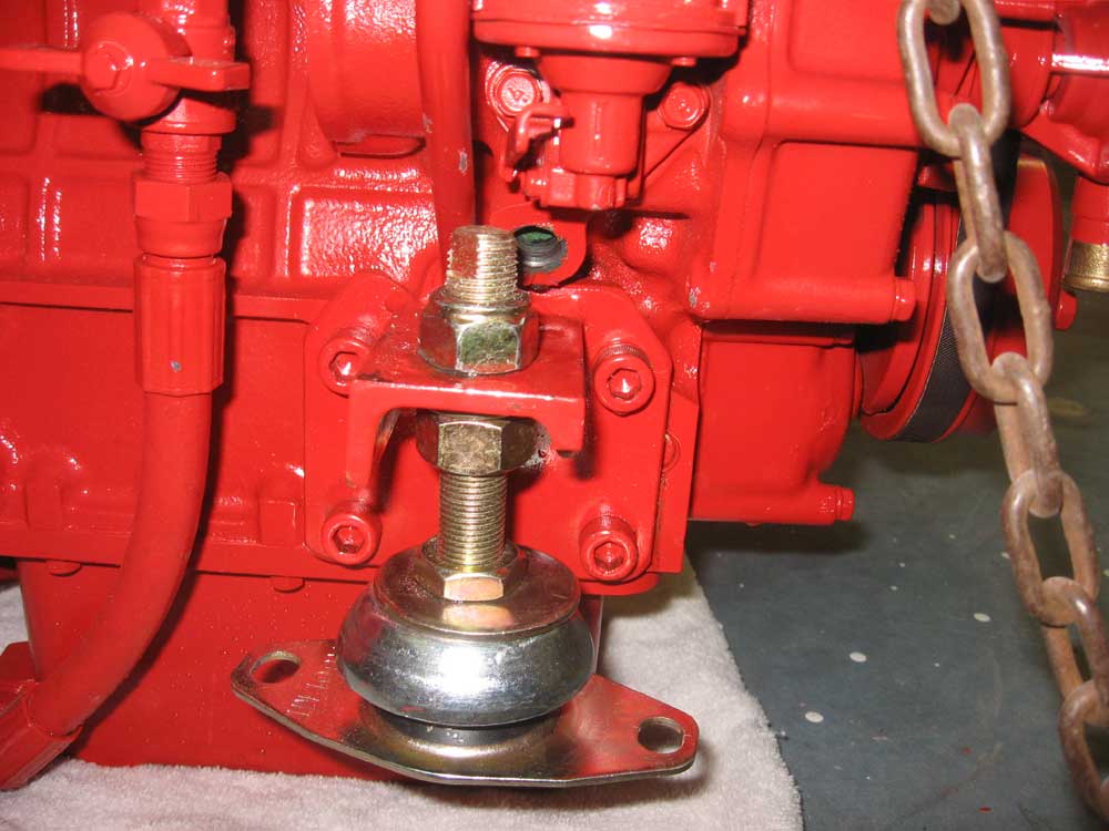
Pressing on, I continued to unbolt the engine from the crate so that I could remove it and prepare to install the supplied flexible mounting feet. I found another perplexing problem with the starboard forward mount: a protruding elbow and petcock drain for the engine block was entirely in the way of the bolt and nut securing the engine to the crate. I couldn't unthread the nut without contacting the elbow well before the nut was free, and although I was able to remove the bolt and nut by continually pushing the bolt downwards as I unthreaded the nut, thereby achieving enough clearance, I knew that there was no way the stud on the flex mount was going to fit in the space, much less the nut. |
|
|
Sure enough, once I raised the engine clear of the crate with my crane and test-fitted the mounting stud, I found that there was simply no way that it would work with that elbow and petcock in place. Besides the fact that the petcock prevented me from attempting to turn the elbow, it was clear that the elbow would be in the way no matter what position it was actually facing. |
|
|
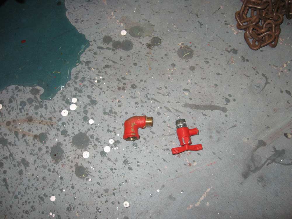
I couldn't even believe that I'd already discovered two such significant issues with the engine, and it was barely free of the crate. Both issues seemed entirely unnecessary, thereby compounding my irritation at their existence. This mounting flange, designed to replicate the narrow centers of the Atomic 4, was a factory option, not some shadetree mechanic's attempt to cobb something together. How could such a significant clearance issue get through production, inspection, and shipping? Are all Beta engines with the narrow mounting flanges subject to this same ridiculous issue? Or was something somehow different on this particular engine for whatever reason? After a few unproductive minutes quietly uttering my true feelings about Beta Marine's engineers (not to mention the seeming need among engine manufacturers to cram everything into the tiniest space possible (or, in some cases, not possible)) to the air in my shop, I decided the only practical means of getting by this issue was to remove the offending petcock and elbow, and to replace them with a plug in the opening in the block. Of course I couldn't unthread the elbow from the block without first removing the petcock; I couldn't even unthread the petcock without loosening the elbow 1/4 turn, so that the petcock would clear the nearby oil dipstick tube. And then I discovered that the mounting flange prevented me from unscrewing the elbow at all, so I had to remove the mounting flange itself. For heaven's sake. Eventually, I got all the pieces off, reinstalled the flange, and reveled in the clear air space around the top of the stud after only an hours' unnecessary work. I ordered a plug to fit the opening, determined that I could install it later, and moved on. |
|
|
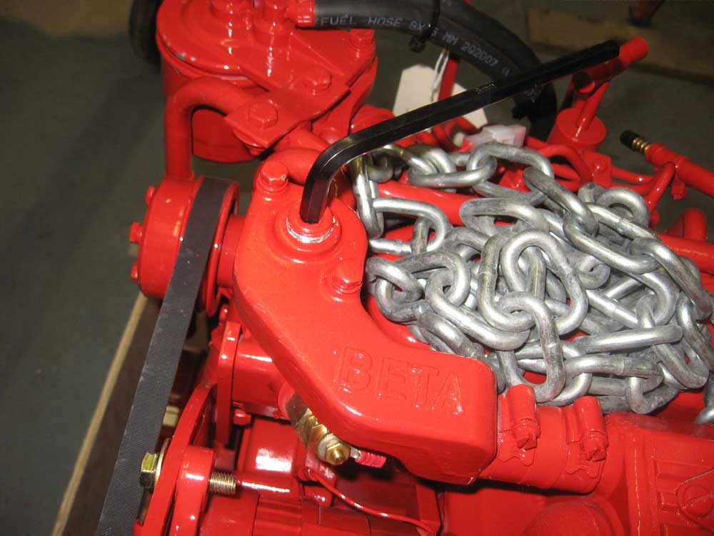
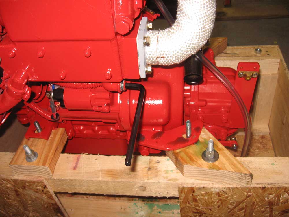
I had a few other preparations to make before I raised the engine into the boat. First off, I wanted to determine where the hoses for the coolant-based firing of the fresh water heater would go. I located the plugs thanks to the supplied manual and used the appropriately-sized Allen wrench to break them free for ease of removal later. I determined the thread size and ordered pipe-to-hose nipples to allow me to connect the water heater hoses. |
|
|
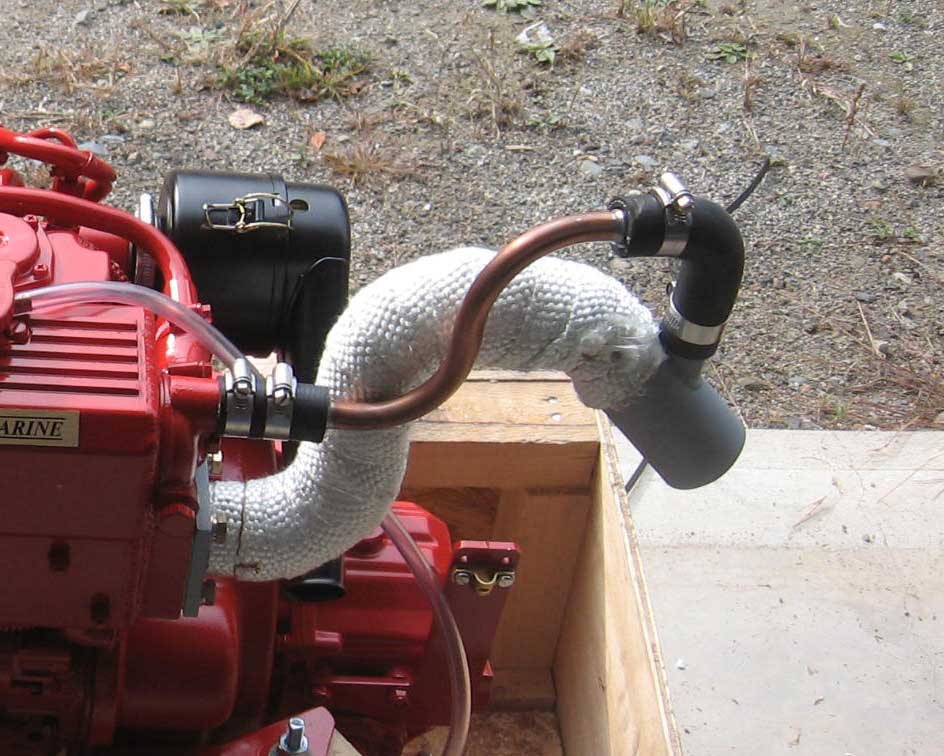
Next, I considered the exhaust riser that came with the engine. Although I had expressed doubts that the taller exhaust outlet would fit in the space available, Allen and I eventually decided that there was no harm in trying it; using it would be ideal, after all, so the engine arrived with a taller exhaust riser that extended a few inches above the top of the engine. However, some initial measurements I made indicated that the clearance would indeed be very tight, at best, so rather than fight with it later I decided to remove the riser before putting the engine in the boat; if I determined that it would fit, I could easily reinstall it later. I unbolted the riser and the associated cooling hose, and covered the openings with tape to keel debris out. |
|
|
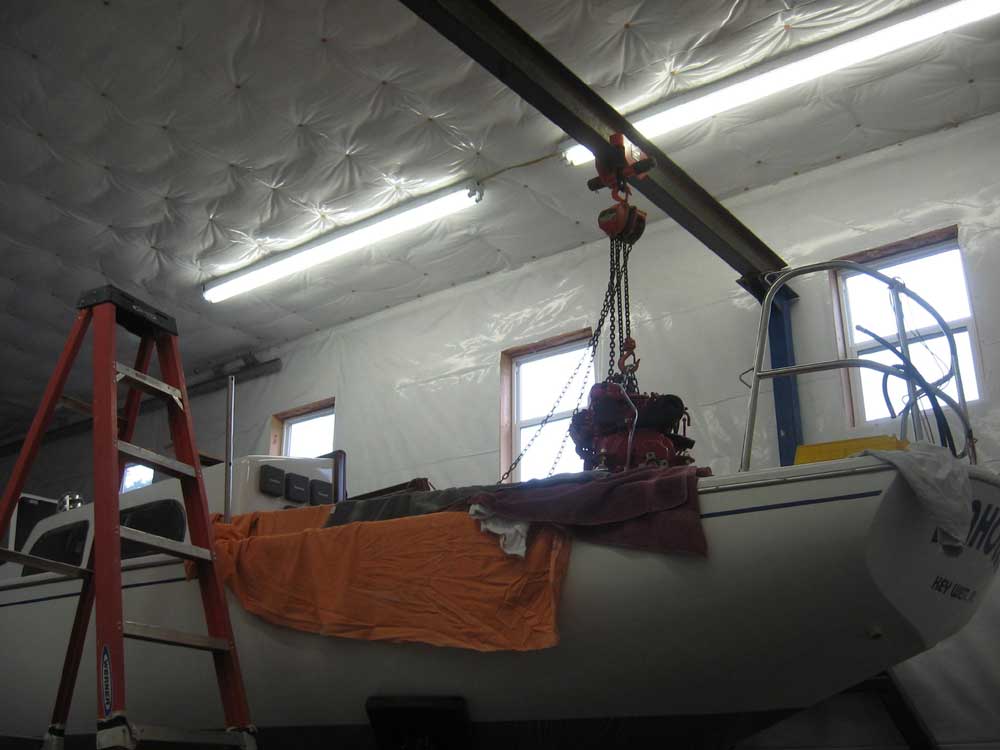
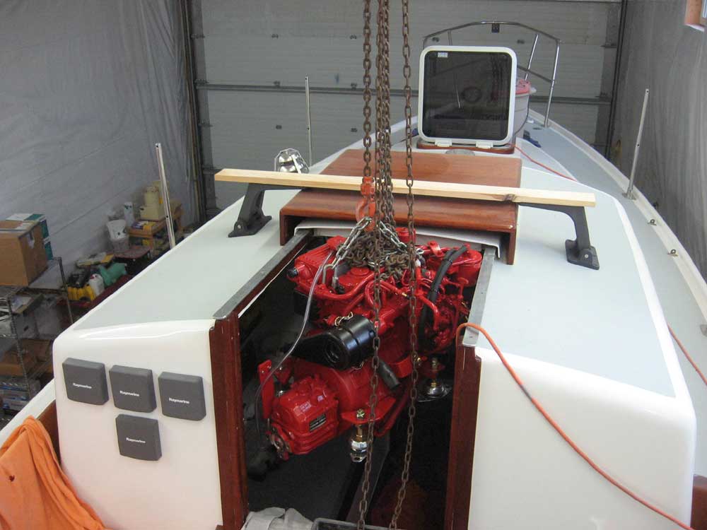
Finally, I was ready to lift the engine into the boat and check its actual clearances in 3D. I raised the engine alongside the boat and then easily rolled it over the rail with the gantry's trolley--the first time I'd had the large-enough gantry available to use for a sailboat engine (though I'd used the unmodified, 10' tall x 8' wide gantry to move the engines in two powerboats previously). then, I rolled the whole thing forward so that I could lower the engine through the companionway. There's nothing like having the right tool for the job, and this had been too long in coming. With the engine inside the cabin, I then eased it into the engine room and set it down on the foundations, sliding it gently into position. |
|
|
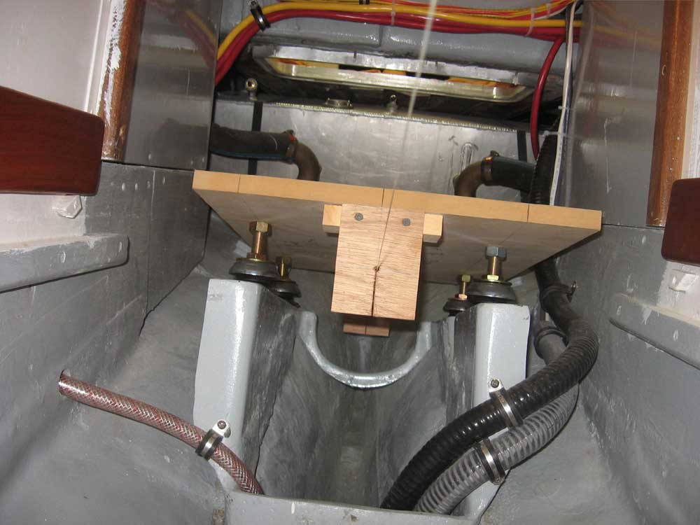
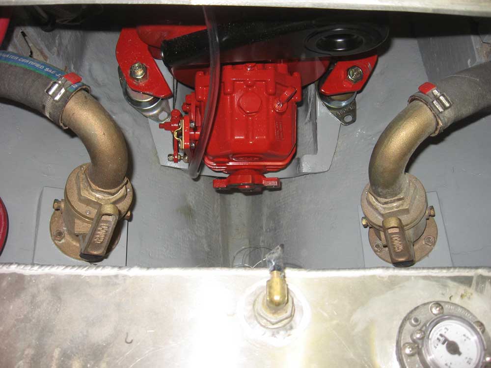
Using the engine room enclosure panels as a guide, I checked the clearance of the front of the engine and moved it aft just enough to provide appropriate clearance with the vertical panel. Then I checked the after end of the engine to see how things fit at that end. As expected, the after mounts would be a bit too wide to use the existing foundations without modification; the after mounts were also further aft than I would have hoped for in an ideal world, meaning that the shape of the hull would interfere with bolting room. That sort of thing was to be expected, however, if not particularly desirable. (Note that in the picture below, I have yet to straighten out the engine mounts, so they are skewed out of position.) |
|
|
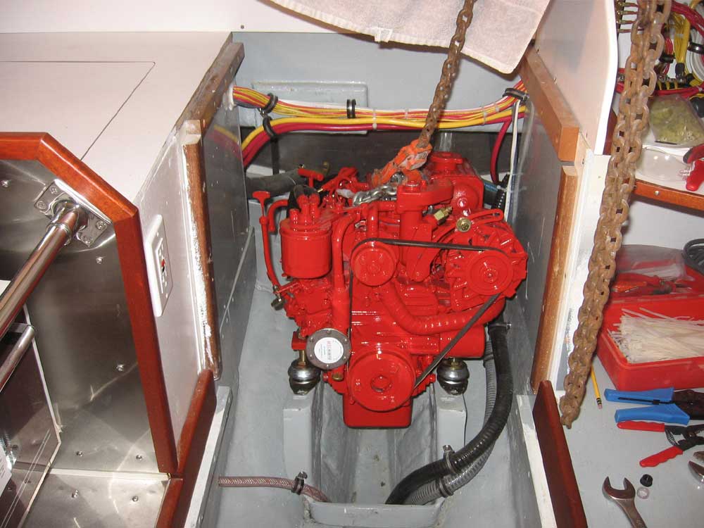
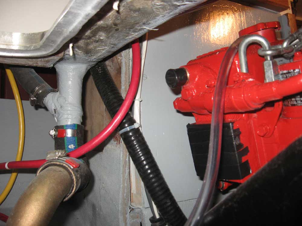
Overall, the engine fit into the space well. The hull clearance issues at the aft end were a challenge even with the old Atomic 4; in an ideal world, it would have been nice to pull the whole engine several inches forward to improve clearance at the after end, but the practical concerns about cabin and galley space, as well as using the existing foundations rather than building new, prevented this. I did discover yet another clearance issue that I had to deal with, however. The way the existing fiberglass foundation was constructed interfered with the transmission shift lever on the engine; the lever contacted the foundation before it could operate through its full range of motion, in two different places. Now, at this point the after mounts were still adjusted a bit too low; the aft end of the engine needed to be raised, and this would improve the transmission lever clearance. But there would still be some clearance issues, so I marked out the areas that would require modification while the engine was still in place. |
|
|
Modifying the foundations at the aft end wouldn't be too bad. Since the engine was too low at that end anyway, it seemed that I could easily add 1/2" to the area, so I planned to build extensions from prefabricated 1/2" fiberglass panels that I could epoxy and fiberglass in place right on top of the existing foundation flanges. This would allow me to extend the width easily to accommodate the wider aft mounting centers. Because of the hull clearance, however, it didn't look like I'd be able to install through bolts and nuts on the after bolt location (the forward location would be accessible). So I planned to epoxy a flathead bolt in place in the new foundation extensions for the after bolt locations; this after end would further be bedded in epoxy to completely fill the space between it and the hull, thereby completely encapsulating the bolt head and adding significant support, strength, and rigidity to the structure. Next, I checked for clearance for the exhaust riser. As expected, there just wasn't enough room. It looked close, and I thought that maybe the elbow itself would fit if I could rework the raw water injection hose (which wouldn't have been a problem), but even with the engine knowingly too low, the top of the riser contacted the cockpit well. While moving the engine several inches forward would have provided enough clearance, this was not an option. There was just no way the riser would fit, so I made arrangements to obtain the stock exhaust outlet; I'd work through the potential seawater backflow issues with the raw water injection hose and the waterlift placement later. The installation would be fine, but it would have been nice to be able to use the taller riser nonetheless. |
|
|
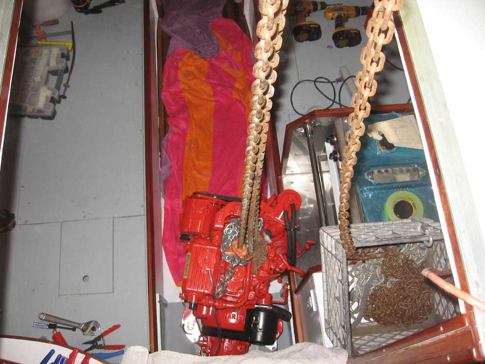
At this point, I pulled the engine out of the engine room and placed it on towels protected with boards protected with towels on the cabin sole for storage while I worked through the remaining installation issues. I wrapped up the day with some additional work on the electrical panel, making a few more connections. |
|
|
|