| Kaholee Refit |
October 16, 2007 I started the day with some woodwork: building the face and side panels for the electronics panel located adjacent to the nav station, and building a new front for the companionway step, down at the base near the sole. Some weeks ago, I made up a cardboard template for the electronics panel, including cutouts for the GPS, VHF, and windlass circuit breaker, and now I transferred this shape to a piece of 12mm Meranti plywood and cut it out. Then, I cut a side panel to close off the front side along the bookshelf. I used the old step front as a template for the new one, after determining that the old fit well enough. The only modification I made was to shorten the new step by about 1/4", or the thickness of the new cabin sole. With the plywood pieces cut, fit, and sanded, I applied a coat of primer and let it cure. Sorry--no pictures right now. |
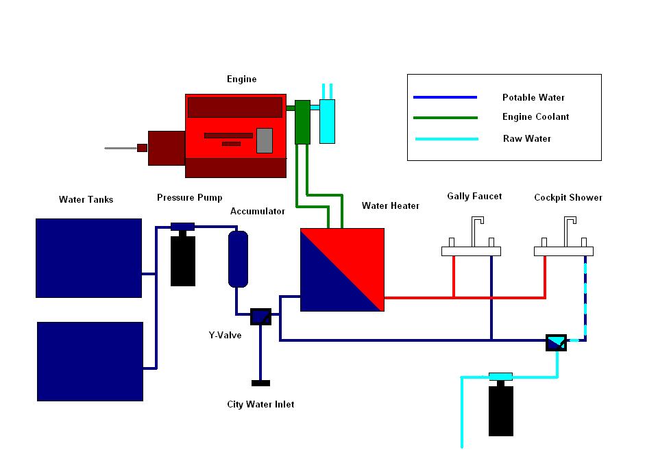
Next, I worked on the plumbing system. I was waiting for electrical parts, so I had to shift focus in order to continue progress. I had a variety of plumbing parts on hand from the owner, so I started with what I had. With all the various pumps and other features already installed, it would be a matter of running the hoses as required. The water system was quite complicated, however, as seen in the owner's schematic below. The system incorporated two fresh water sources (tank and city water connection), plus pressure salt water, plus hand-pumped salt water to the galley. Interconnecting the various means required a couple Y-valves to control the sourcing of the water flow; these are represented by the little boxes shown in this schematic. |
|
|
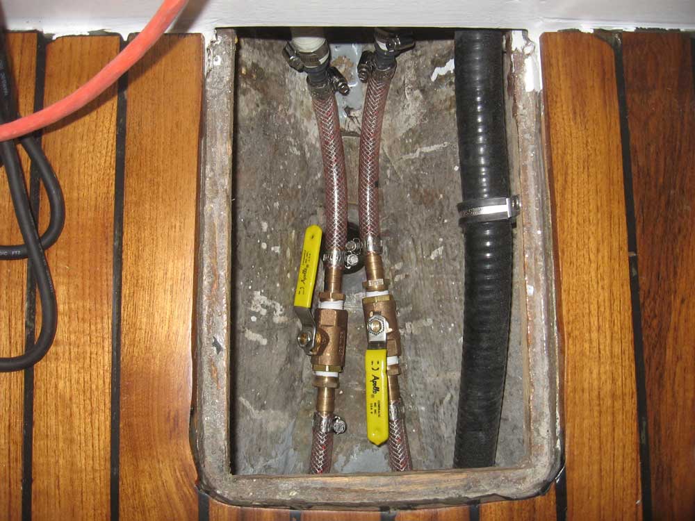
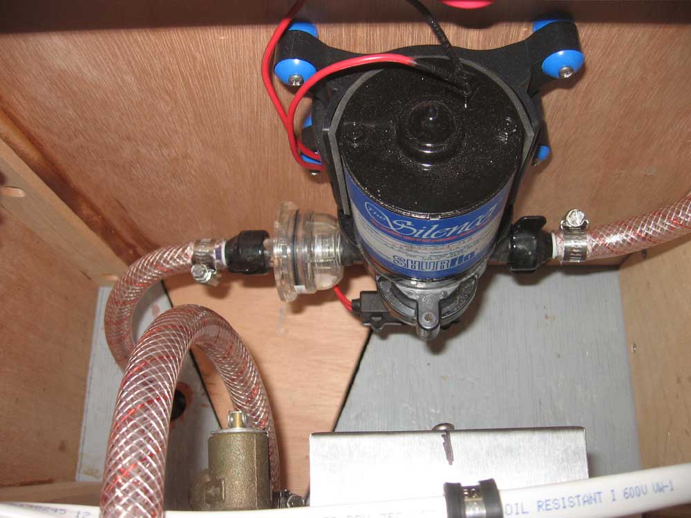
I began at the fresh water tanks beneath the v-berth. Starting with the adapters I made up and had previously installed, I installed bronze shutoff valves on each supply line, to allow the water supply to be isolated or combined as required. Then, I connected the lines together with a T-fitting, and ran the supply line aft and through a pre-existing hole in the bulkhead and to the fresh water pump in a locker beneath the galley. I then installed a short length of hose to connect to the inlet side of the adjacent accumulator tank. |
|
|
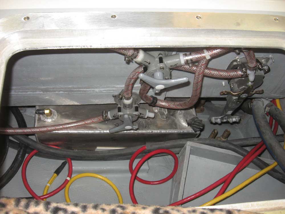
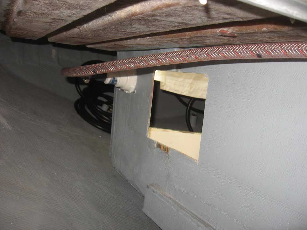
Next, I installed one of the Y-valves inside the starboard cockpit locker, where it could be easily seen and reached, and ran a hose from the back of the city water connection to the valve. Then, I ran another line from the accumulator tank to a second leg of the Y-valve, and a third line from the output of the valve, through a T-fitting, and on to the inlet side of the water heater (also located beneath the galley). A second Y-valve, which I installed adjacent to the first, would serve to split the water supply between fresh and salt water for the cockpit shower fitting only. At this point, I ran out of hose and clamps. Of course, several of the hoses have yet to be attached in these photos, so bear with me and eventually the system will be complete. |
|
|
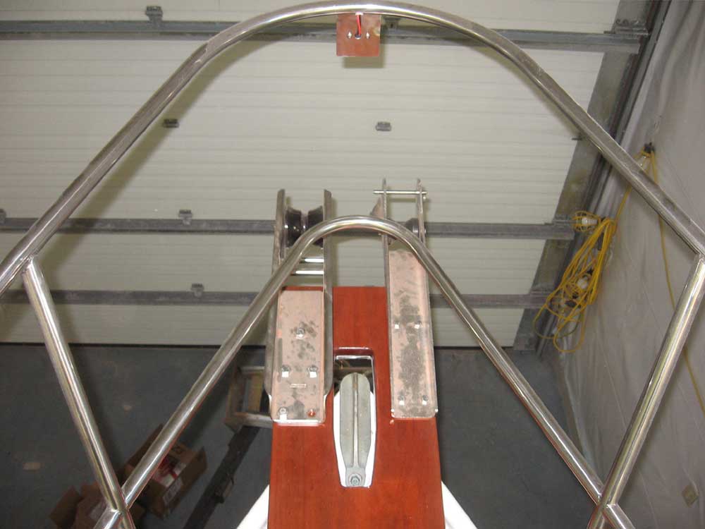
I also installed the second anchor roller, having received the correct size bolts at last. |
|
|
|
|
|