| Kaholee Refit |
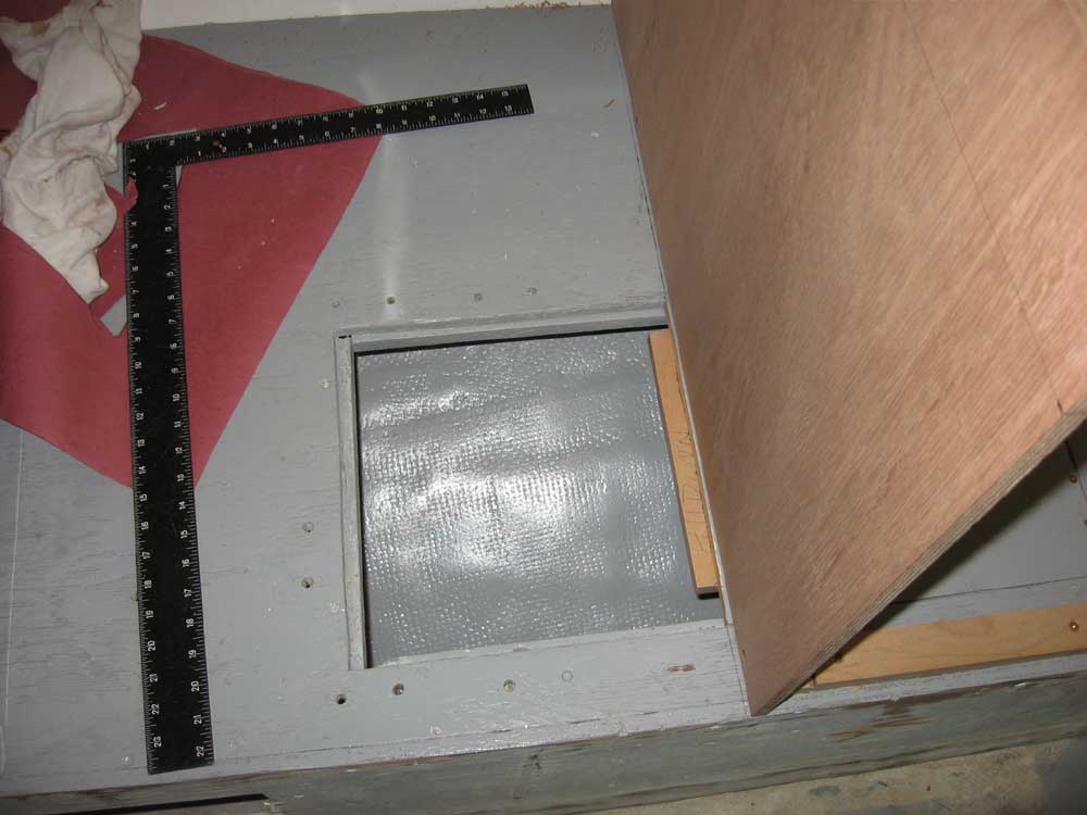
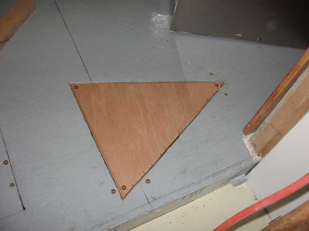
March 15, 2007 I spent the first part of the morning working out the details of the new stove cabinet. There were several factors at hand that were critical to the overall size and location of the cabinet. First and foremost was the location of the forward bulkhead, which, as discussed previously, needed to accommodate the length of an existing settee cushion. That part was easy enough. I even found that I could move the forward bulkhead about 1/2" further forward than originally anticipated, which was good news for the entire process. Another factor to consider was the overall height of the stove when fully installed, allowing for room for the stove to swing on its gimbals as intended. A comfortable height for working is 36" from the floor, and I used this as my guideline during the layout; this was also the height at which I built the sink cabinet. There was plenty of room available to mount the stove above the surface of the existing settee and still have enough swing room, but ensuring that this was so was an important part of the overall layout. In addition, the stove required certain minimum clearances to the side and rear to allow for proper airflow and heat removal--3/4" on each side, and 1-1/2" at the rear. These dimensions, along with the size and design of the gimbal brackets, all played important roles in the construction of what is, on the surface, a relatively simple cabinet. I also had the hot water heater to consider, as I touched upon yesterday. Since the stove location was basically set and couldn't be adjusted, I could only hope that I'd end up with sufficient space aft of the stove to allow the heater to be removed from beneath the new aft galley cabinet. As it turned out, there was. With the most basic layout determined, I pressed on with some actual construction. First, though, I had to address a couple small issues with the settee itself. The new stove cabinet would cover half of an existing storage locker lid, so once I made my layout marks I cut the lid in the appropriate location and secured the aft half, which would be hidden beneath the new stove; the forward half, with the addition of one extra cleat, remained operable and accessible. There was also a triangular hole in the settee top at the after end of the new stove location, which had once provided hose access for the galley sink drain. I filled this in with a plywood patch. |
|
|
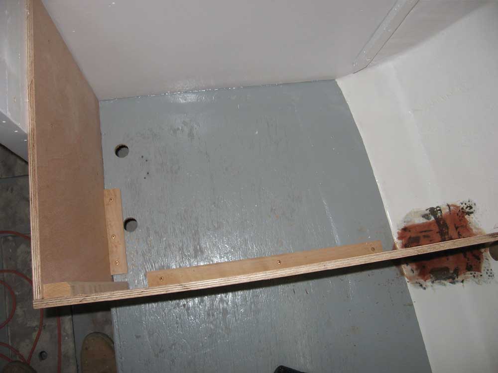
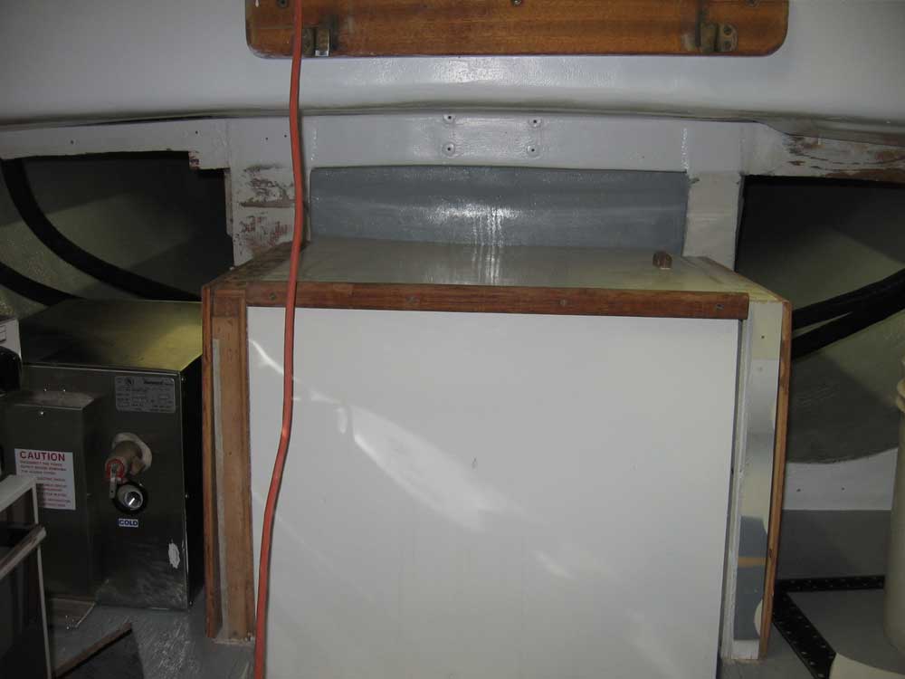
Before continuing, I took a moment to glue and screw a couple hardwood cleats inside the sink cabinet, thereby completing its installation by fully securing the base of the plywood. I also installed the existing panels that covered the engine room, since I anticipated reusing these, and further anticipated installing the new after portion of the galley countertop to be even with the top of the engine cabinet. However, I noticed a problem with the engine room top--the top was clearly skewed to one side and not level (it's lower to the port side, or the right side of the photo below). Some further investigation revealed that while the two sides of the engine box were the same height above their respective settees, the port settee was substantially lower than the starboard, which led to this misalignment. Fortunately, this didn't represent a major problem, but nonetheless would be one more thing to take care of during later construction steps. |
|
|
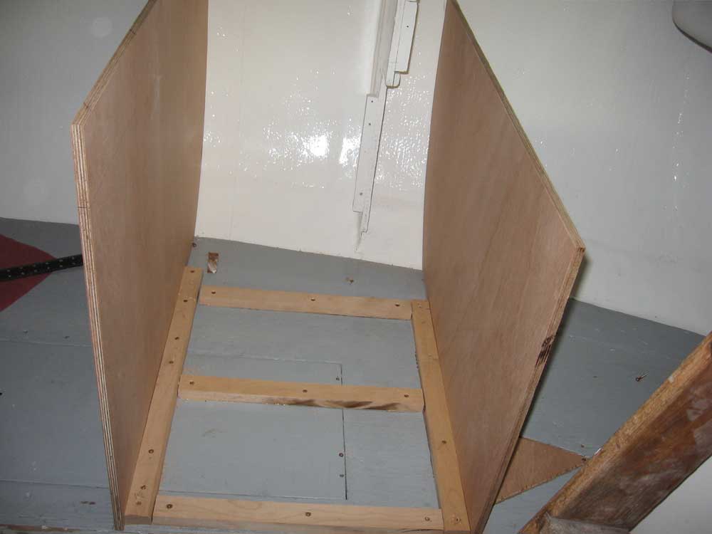
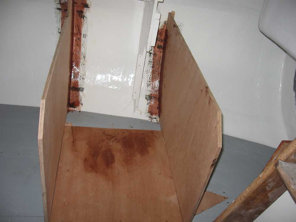
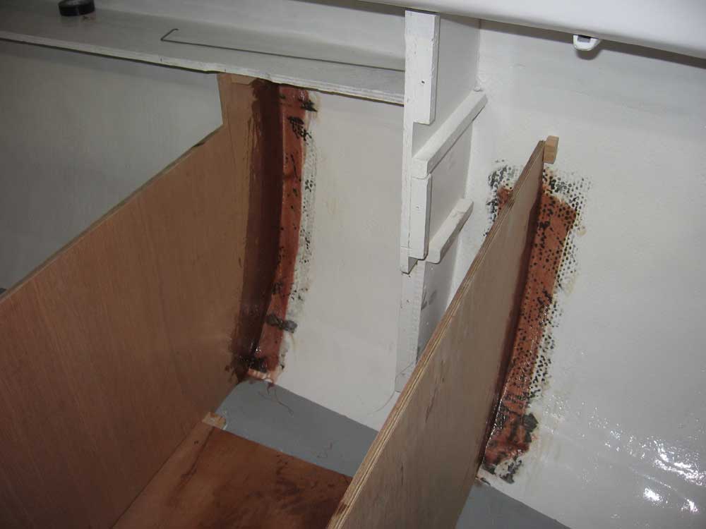
Next, I installed hardwood cleats, against which the bulkhead could be secured, on the settee, using a bit of glue and screws, and also beneath an existing shelf against the hull. I roughed out the shape of the forward section of the stove enclosure, and then scribed it to fit closely to the hull on the outside. With a little fine tuning, the bulkhead slipped into place, and I made some marks for final trimming at the inboard end. As with the sink cabinet, I used the settee top as my static reference point. Once I had a satisfactory fit, I secured the bulkhead temporarily to the cleats with 2 or 3 screws while I continued with the layout and construction of the after section. With one section installed, I determined the location of the after section, using the stove's width and required clearances as a guide. Once I determined the location, I installed another hardwood cleat, and then followed the same process outlined above to cut and fit the after bulkhead, and installed it temporarily with screws. At this point, I determined that there was enough room between the stove cabinet and the cabin trunk structure to install or remove the water heater from its intended location aft of the stove, which I had suspected would be the case. But there was no extra room! To hide the cleats to which I secured the bulkheads, and to also provide a flat, clean "floor" for the stove cabinet, I installed a 9mm plywood base above the cleats. To better support the floor, I installed some additional cleats, and then glued and screwed the base in place after determining an overall length (depth) that would be sufficient to allow for stove clearance. I finished up the day by permanently installing the two new bulkheads. As before, I first removed paint from the hull ceiling, and then installed the bulkheads in a bed of thickened epoxy, which I filleted along the corners, and finally some biaxial tape. To help hold the top edge of the after bulkhead in its proper orientation, I hot-glued a small block to the hull to prevent the bulkhead from springing aft. |
|
|
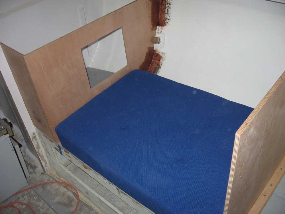
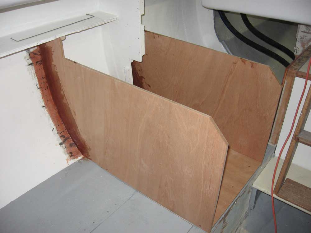
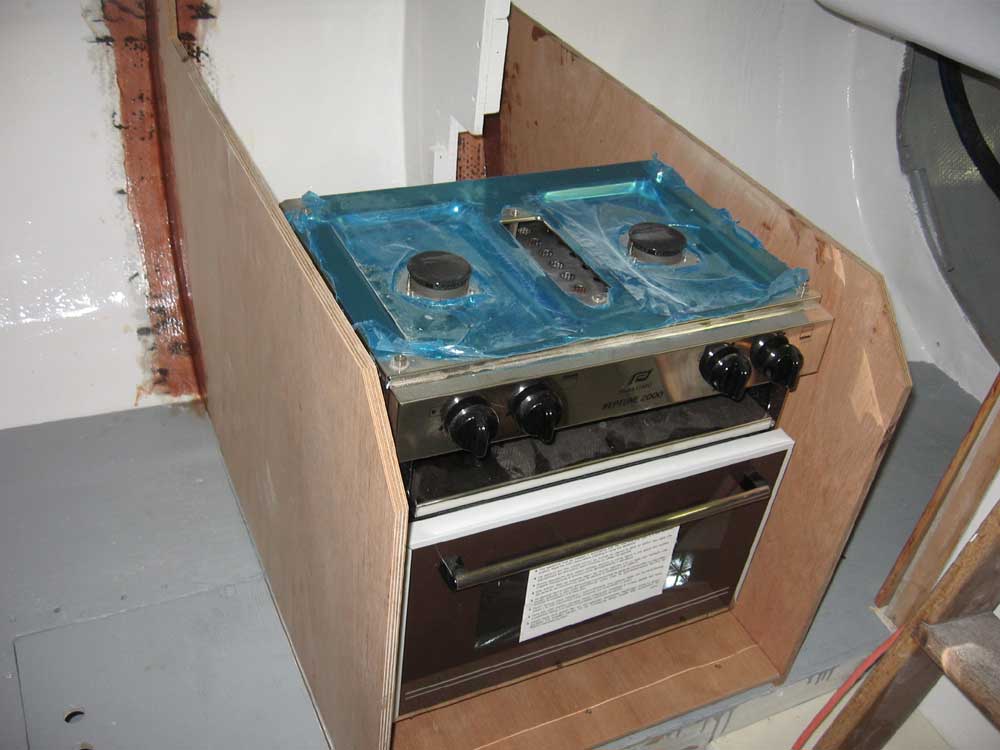
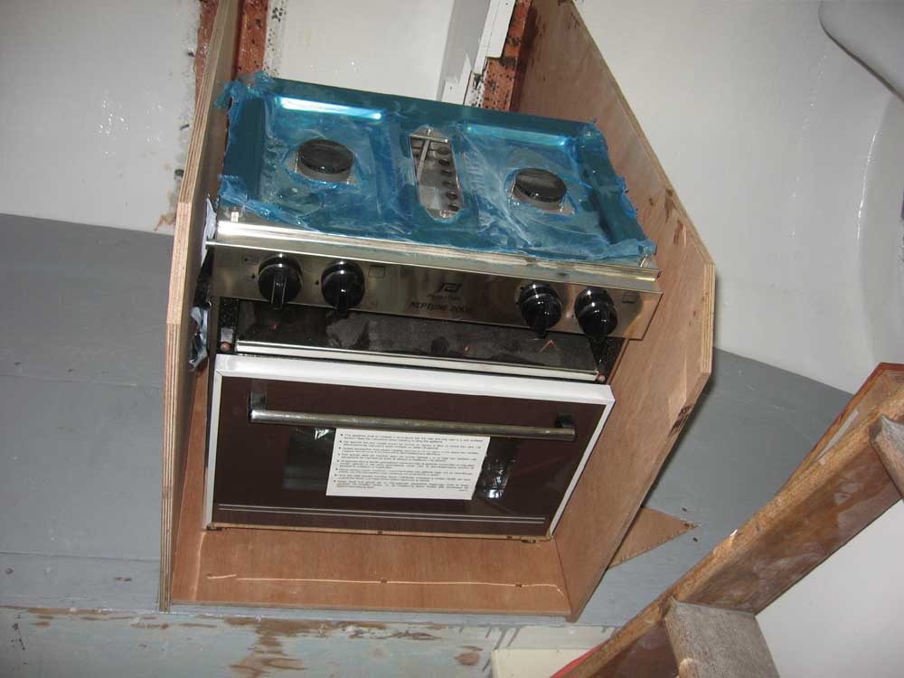
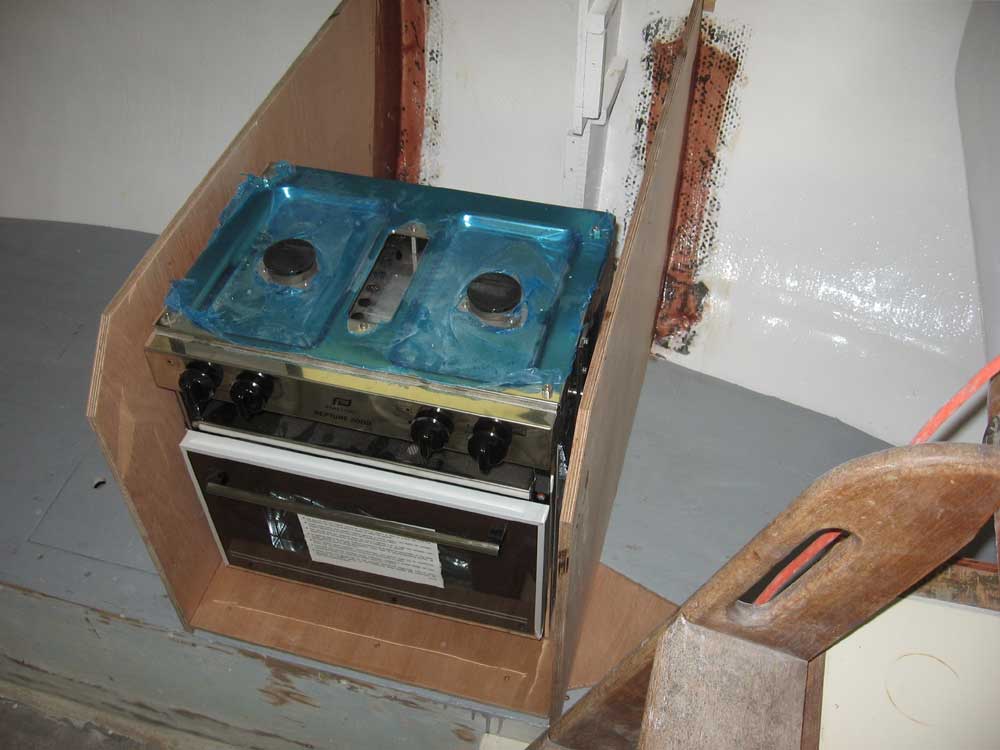
These photos show the stove roughly mocked up in position inside the new cabinet. Here, it is simply sitting on the cabinet base; the actual installation will raise it up a couple inches, so that the top of the stove is roughly even with the edges of the cabinet. This will provide the necessary clearance beneath the stove for its full range of gimbal motion. |
|
|
|
|
|