
|
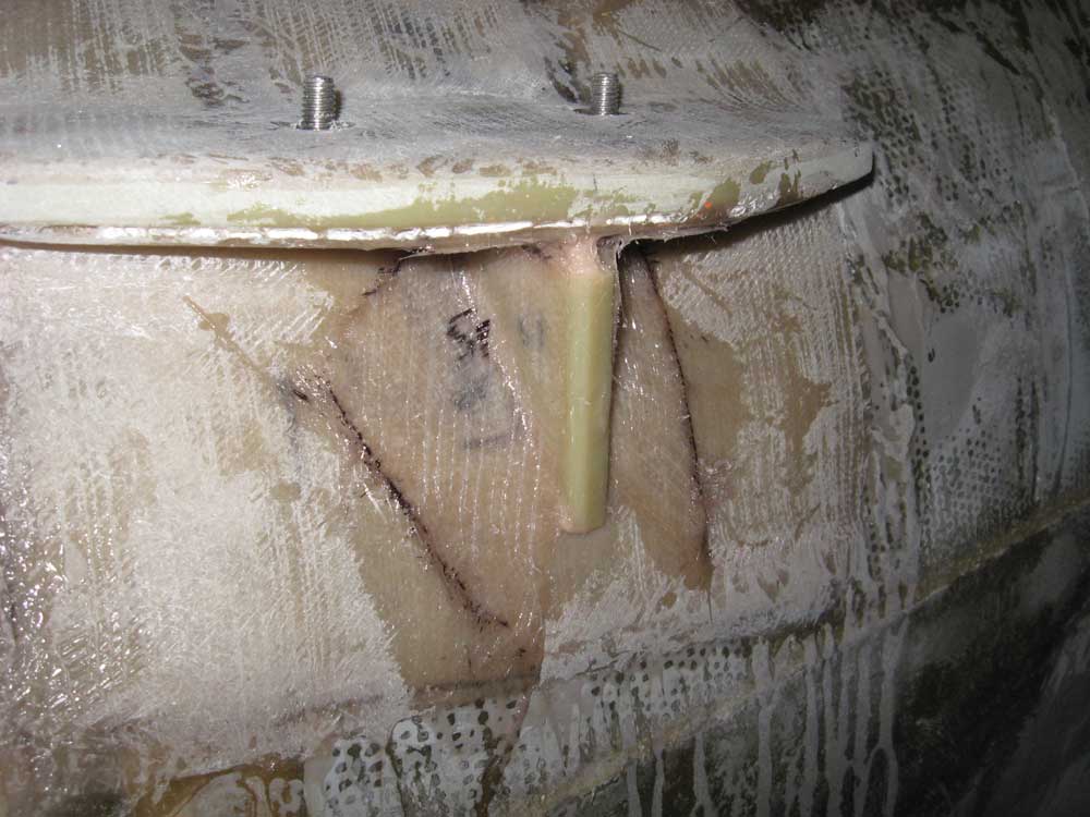
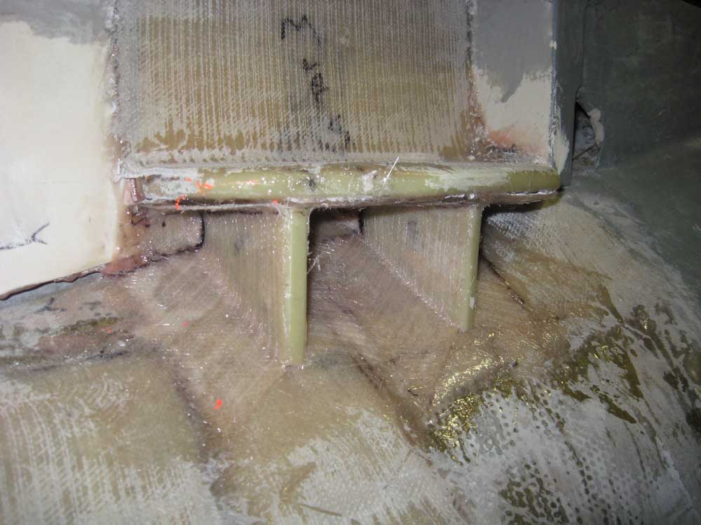
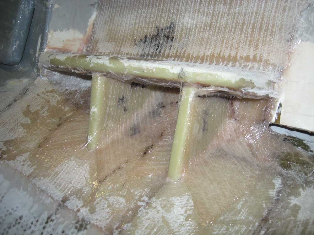
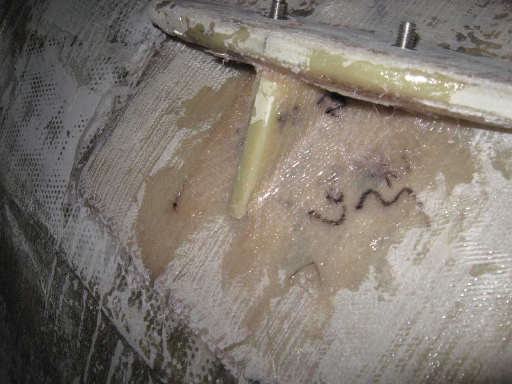
Equinox Project | Tuesday, March 10, 2009 I spent a few minutes cleaning up and fine-tuning the plywood engine mount mockups and then set them aside to deliver to the machine shop tomorrow. To further reinforce the engine foundations in the boat, I elected to add some support braces beneath, located strategically as needed. The way the after foundations were, I decided to add one brace in the center of the engine flex mounts' locations, leaving plenty of room for the future bolts, and an additional support towards the forward end of each platform. The after ends were partially supported by the hull already, and didn't require any further support. On the two forward foundation platforms, I decided to add a single support directly beneath the flex mount location. To proceed, I made some cardboard templates to fit as needed in each location, and then replicated the shapes from 1/2" G-10 scrap. I cleaned up the edges, and then cut fiberglass tabbing to use to secure them in place. After solvent washing the mating surfaces and surrounding areas, I applied thick epoxy to the sides of the braces and installed them, cleaning up the epoxy and forming fillets as needed. Then, I installed the fiberglass tabbing to secure the braces to the hull and to the undersides of the foundation platforms as needed. |
  |
|
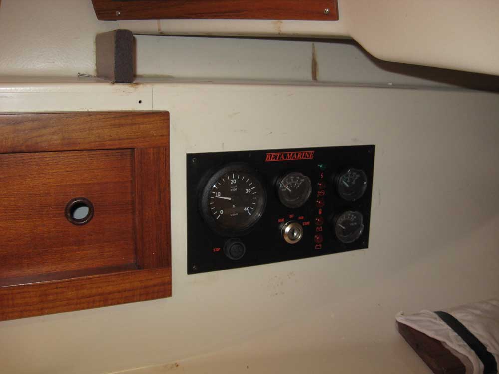
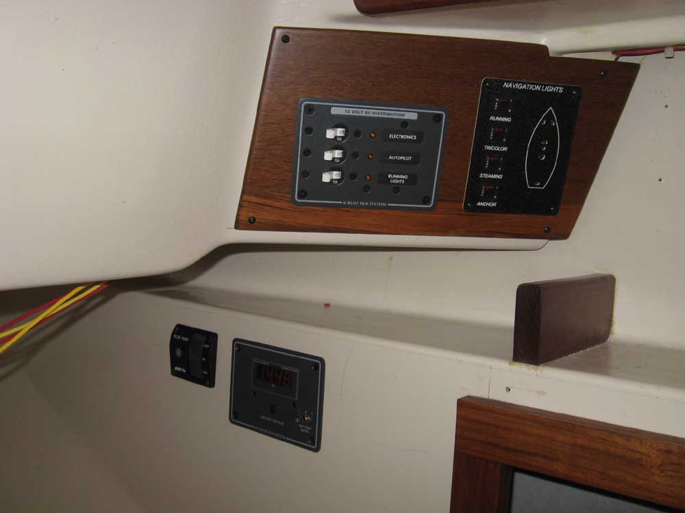
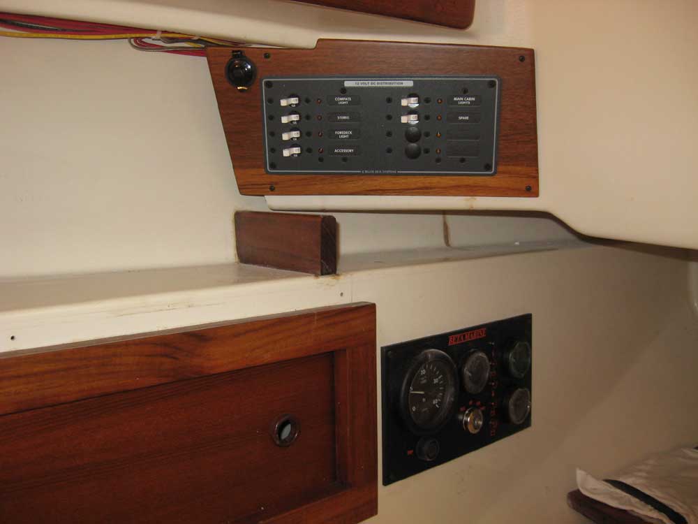
With engine-related work complete for now, I moved forward on some of the electrical system installations. I began by jigsawing out the opening for the Beta Marine engine gauge panel, which I then plugged into the already-run wiring harness, and screwed the panel into place. |
 |
|
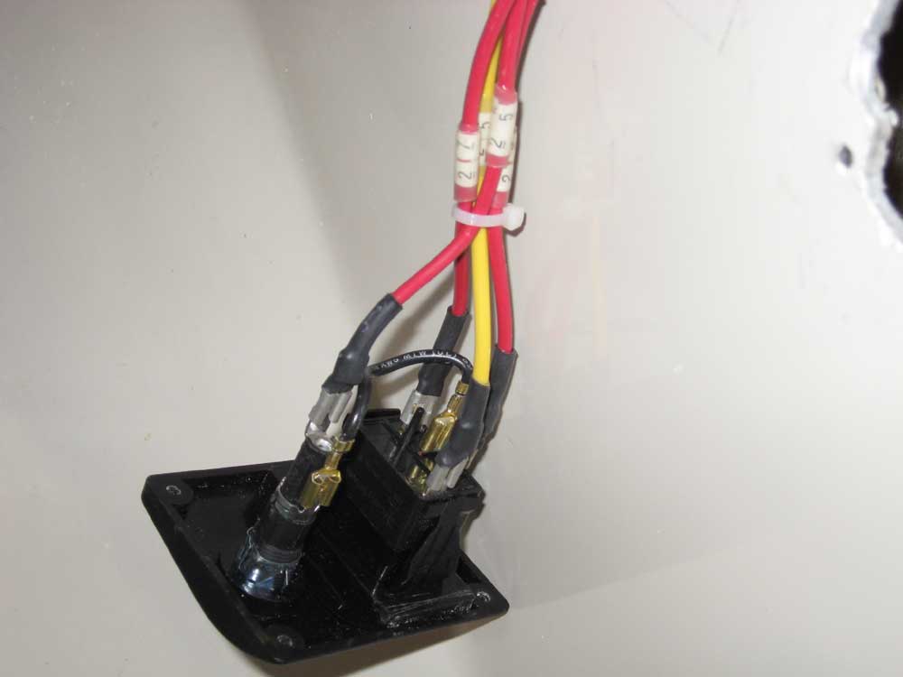
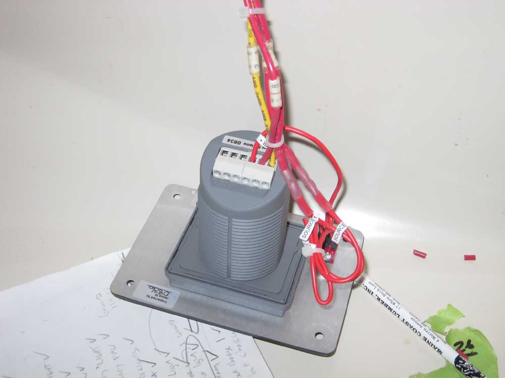
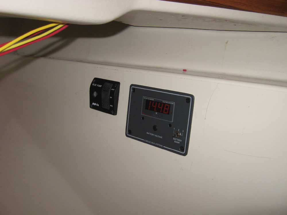
I continued on the other side and cut the
openings required for a digital voltmeter panel and rocker-type bilge
pump switch. Then, I secured labels to each wire, as always, and
made up the wiring connections before securing these panels in place.
I pulled the slack out of the wires (leaving loops of wire behind each
panel to allow them to be removed for service) and tied up the wire runs
beneath the settee. Note that the voltmeter reads 14.48 because there is a protective sticker over the display, which is printed with this figure. |
  |
|
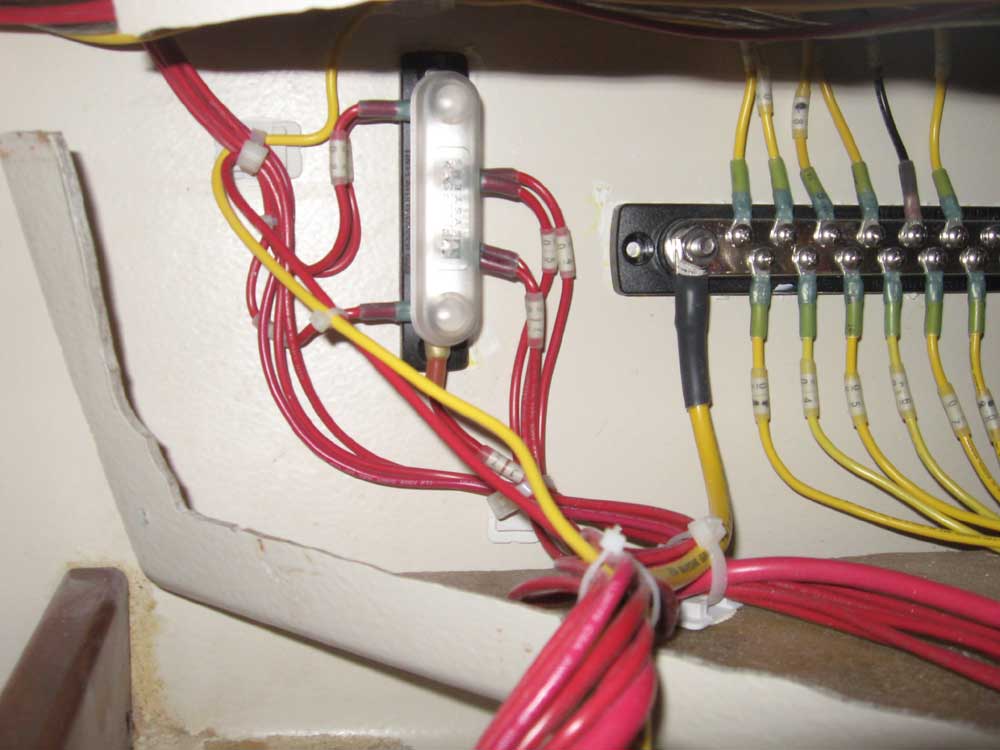
I removed the starboard distribution panel and glued on a new wire tie base beneath the cabin light distribution buss; while I was at it, I glued on a number of additional bases that I needed elsewhere for existing and future wire or cable runs. I installed a plastic cover over the cabin light buss. I'd run wiring and speaker cable for a future stereo, but since we didn't plan to install that immediately I bundled the wires and pulled them back into the space behind the nearby panel, where I tied them up and labeled them for future use as needed. Then, I reinstalled the panel, this time with the black-colored stainless steel screws that I hadn't had on hand when I installed the panel last week. |

 |
|
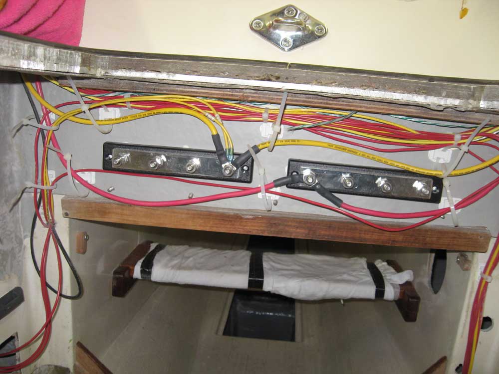
Next, in the engine room I cut to length and crimped on the ends for the main panel feeds (positive and negative), and secured these to the main distribution busses at the forward end of the engine room, leaving the wire ties and cable runs loose for now pending further cable runs. I also led the main bilge pump power feed over to the "always hot" buss on the starboard side, and connected negative wires from the bilge pump and voltmeter panel to the negative distribution buss. |
 |
|
|
|
