| Circe
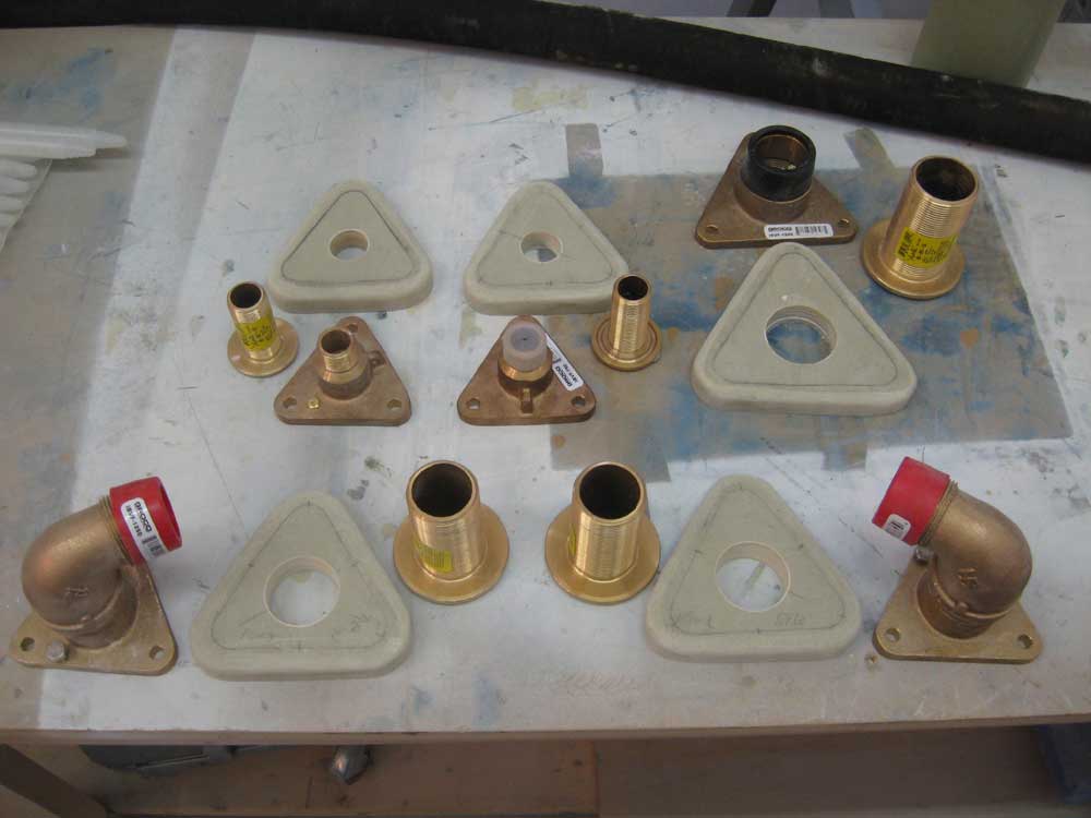
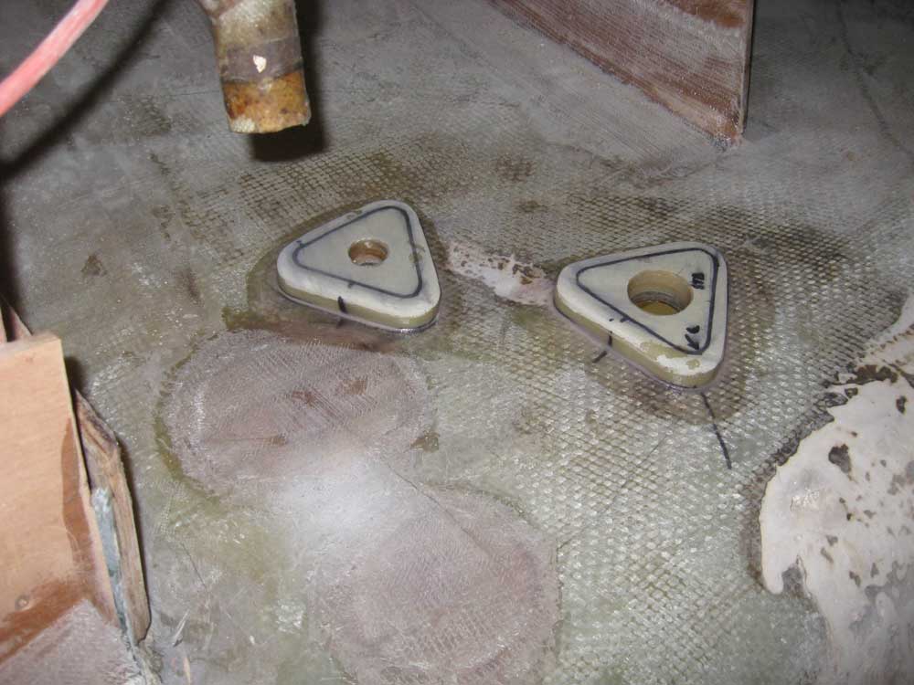
| Thursday, October 22, 2009 With a growing desire and need to wrap up work in the area aft of the cabin and beneath the cockpit while things were still relatively open, I decided to start the through hull installation. To begin, I cut a series of backing plates for the fittings I had on hand (I'd need one or two more through hulls and valves to complete the installations, depending on the final choices and layouts in the forward cabin). For this installation, I again chose Groco's relatively new IBVF flange adapters, coupled with bronze mushroom through hull fittings and bronze inline valves. I liked these fittings because not only do they allow easier maintenance or replacement of the valves themselves (without a need to unbolt and unseal a through hull and seacock to do so), but also allowed more versatility in installation configuration--a handy thing when working in tight spaces like those found here. From 3/4" G-10 left over from the new chainplate knee construction, I cut a backing plate for each of the through-bolted flange adapters--a slow process thanks to the toughness of the laminate--and rounded over the top edges for superior appearance and to remove sharp edges. Then I drilled out the centers to accommodate the through hull fittings. |
|
|
|
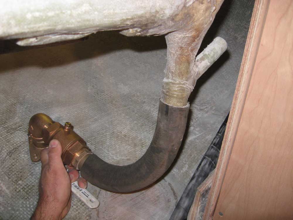
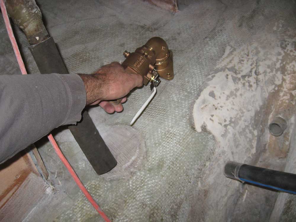
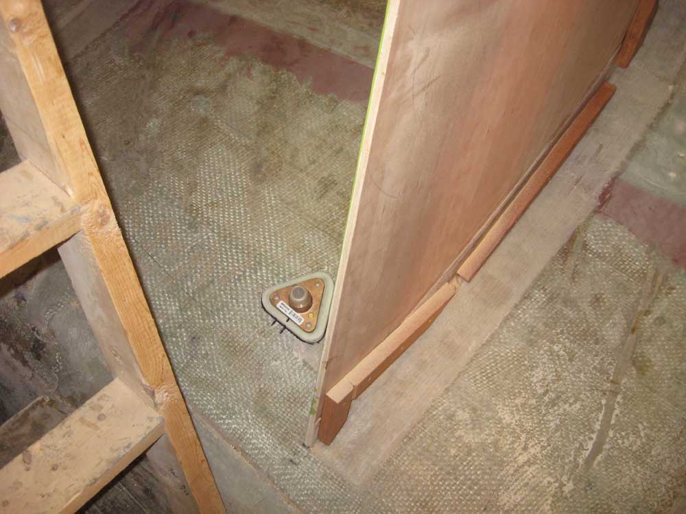
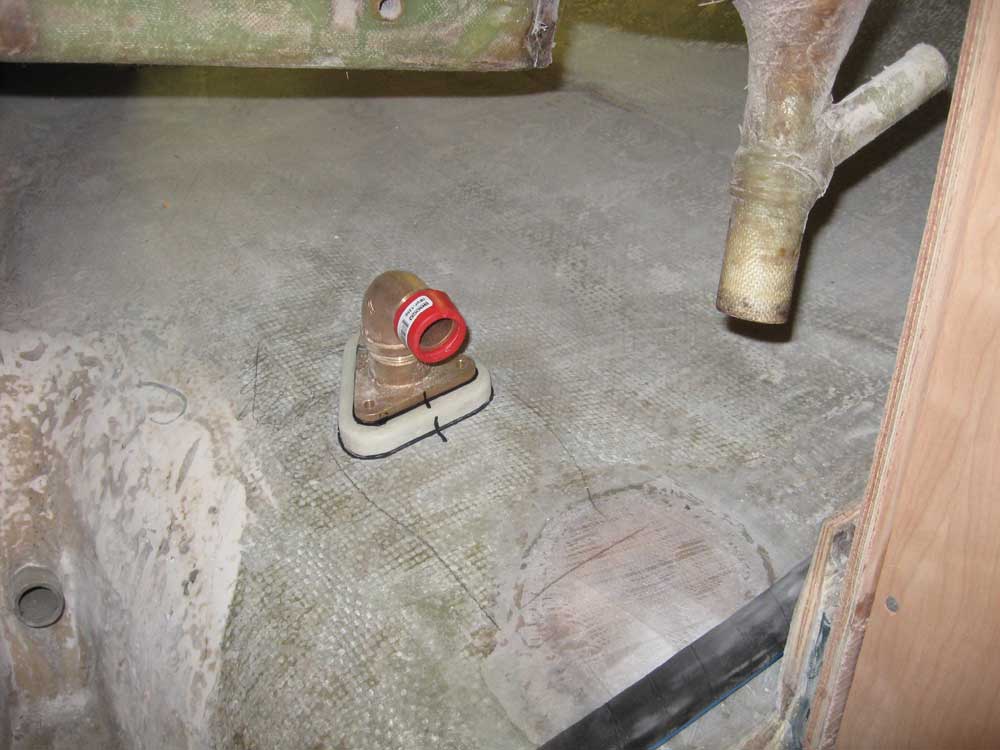
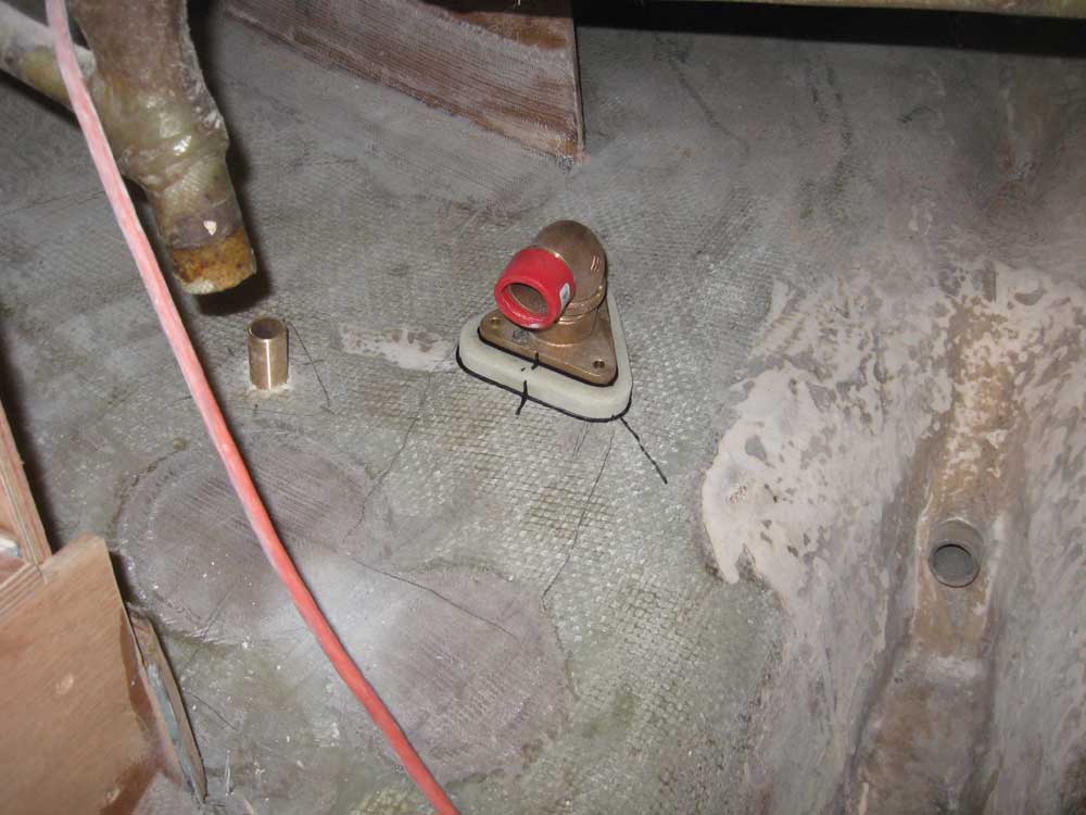
One issue common to Tritons is the lack of vertical clearance between the bottom of the cockpit and the hull, making installation of cockpit scupper seacocks--and particularly hoses--a challenge in all cases. With wide-open spaces available and the flexibility afforded by the flange adapters, I decided to use bronze 90° street ells to redirect the valve angle from vertical to horizontal, which would allow easier hose runs. I permanently installed the ell on each of the scupper flange adapters, tightening them securely in a bed of thread sealant. I pre-installed the ells to ensure that I could install and align the valve properly with the direction from which the hose would naturally run. Ideally, the valve would be screwed directly to the flange adapter, without the ell in between, but there was virtually no chance of failure of the cast ell fitting, and given the space and other considerations it was worth more to be able to redirect the valve's orientation. I temporarily installed an inline valve and tailpiece, and then, using a short section of hose attached to the fiberglass cockpit scupper outlets, allowed the hose and valve assembly to more or less determine its own logical location, rather than attempting to force the location into some pre-determined area. This would allow easier manipulation of the hoses later. In this case, the location ended up a bit further aft of the original locations (which had been simply fiberglass tubes secured to the hull directly beneath the scupper outlets). Ignore the position of the valve handle in these photos: the valves were not tightly secured for this process, and in the final installation I'd line up the handles on the top of the valve for easy access and operation. |
 |
|
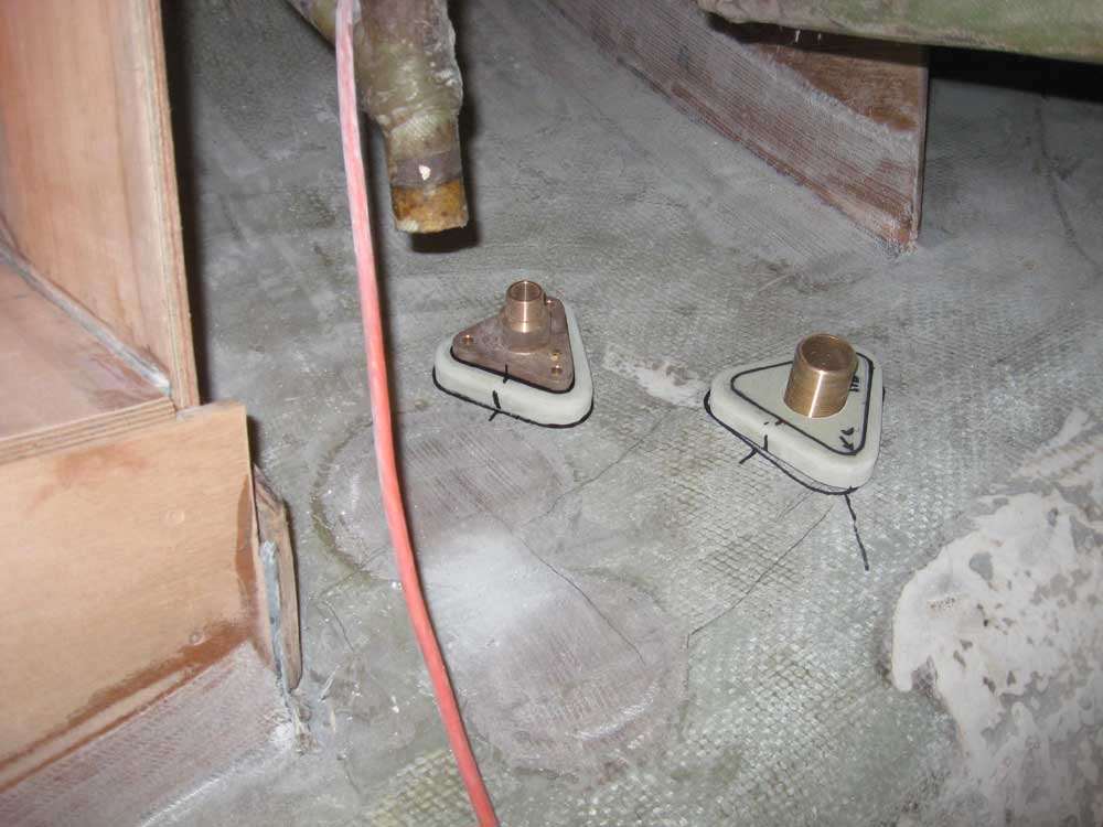
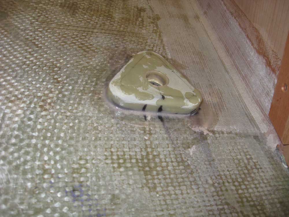
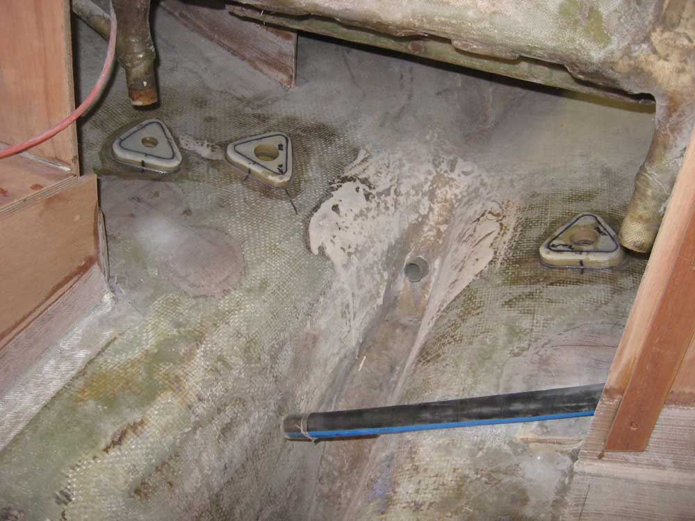
Once I was happy with the location on one side, I marked the hull with the outline of the flange for future reference, and followed the same process on the opposite side--keeping the second side in the corresponding position for symmetry. |
 |
|
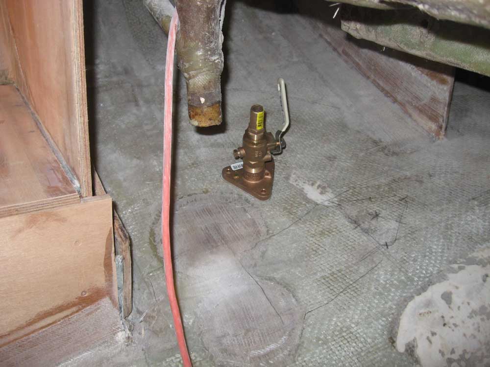
Next, on the starboard side I decided where to locate the intake valve for the engine raw water supply. Keeping the valve well away from the scupper assembly, but still easily accessible from the cockpit access hatch, I marked the location on the hull. |
 |
|
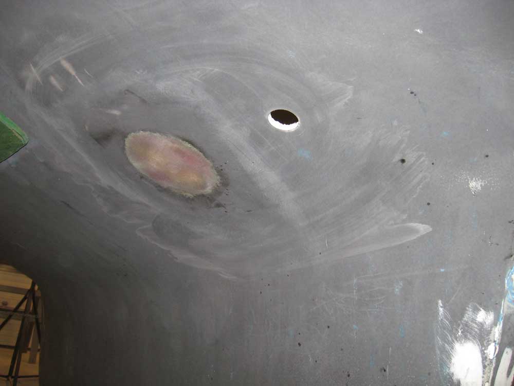
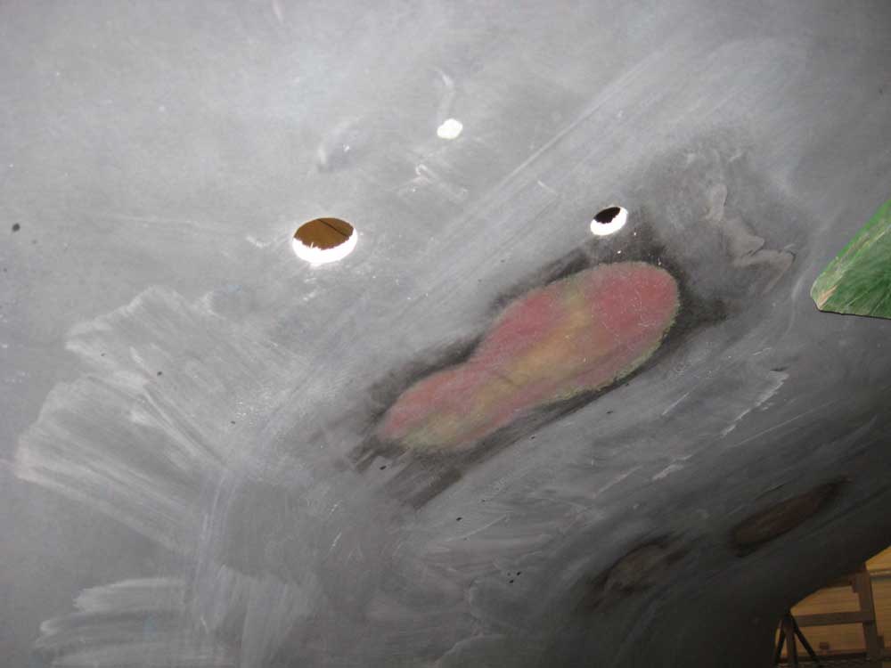
At the galley, I first made some measurements to determine the location of the approximate static waterline, and transferred these to the cabinetry to ensure that the sink I planned to install would end up well above the waterline (it did). Having thus determined that a normal drain would work in this case, I determined a convenient location for the drain through hull and seacock, and marked the hull accordingly. Finally, I marked the centers of each location and drilled a small pilot hole through the hull from the inside, so that I could find the spots on the outside of the hull and enlarge the holes to their final sizes with a hole saw. For now, I left the remaining through hulls--those in the forward cabin/head--for later, since I didn't yet know where they needed to go, and there was not an access or time consideration for their installation. With the large holes drilled, I test-fit each through hull fitting, backing plate, and flange adapter, and made indelible marks to help me align the backing plates during final installation. |
 |
|
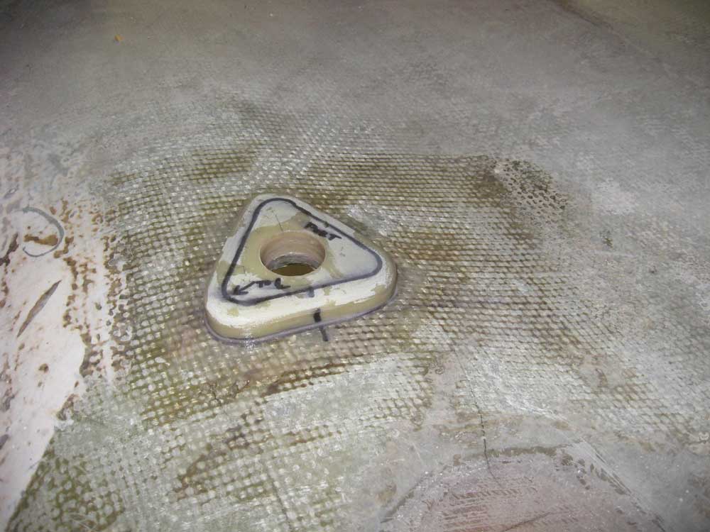
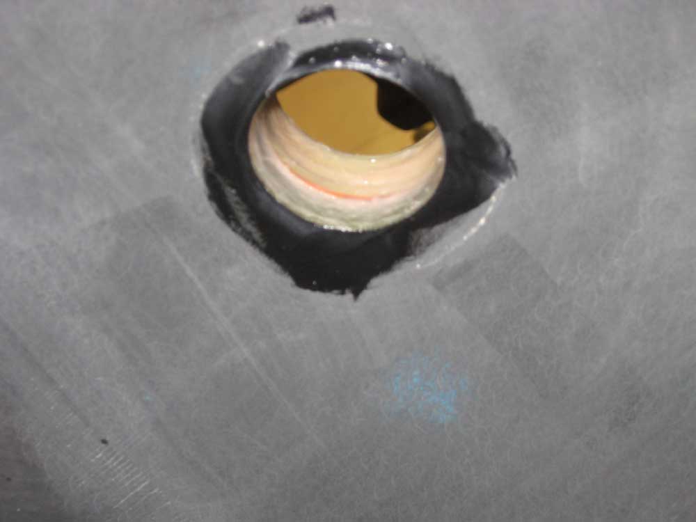
At the very end of the day, I vacuumed and solvent-washed the hull in way of each of the four through hull pads I wanted to install, and then secured each pad in an adhesive bed of thickened epoxy. I waited till the end of the day so that I wouldn't accidently knock one of the pads, or have vibrations in the hull cause one to slip out of position. Partly through luck and partly by specific plan, each of the installations had ended up on a generally flat-ish section of hull, meaning that the through hull backing plates would fit flat against the hull (and, conversely, that the mushroom heads would lie similarly flat); this eliminated much of a need to over-fill the areas, and made it easy to properly align the pads. I cleaned up the squeezed-out epoxy from around the edges, and ensured that the hole in the pad lined up perfectly with the hole drilled in the hull. |
 |
|
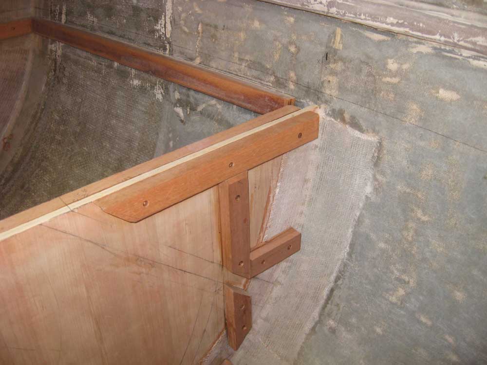
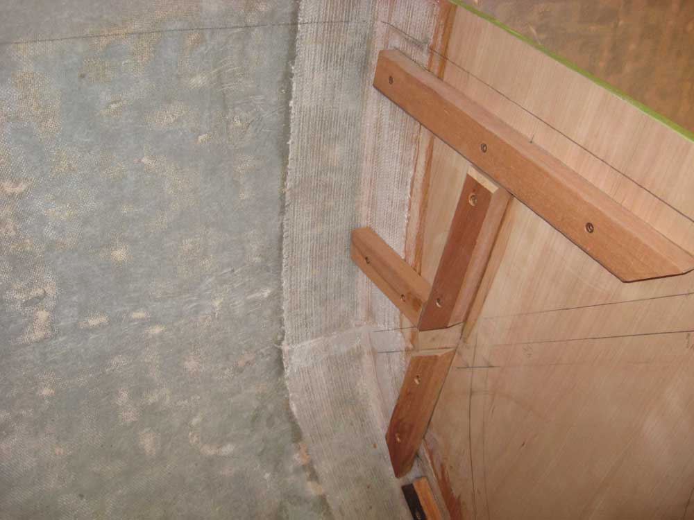
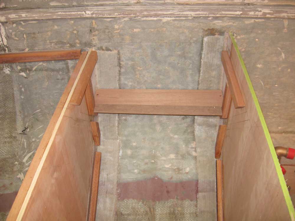
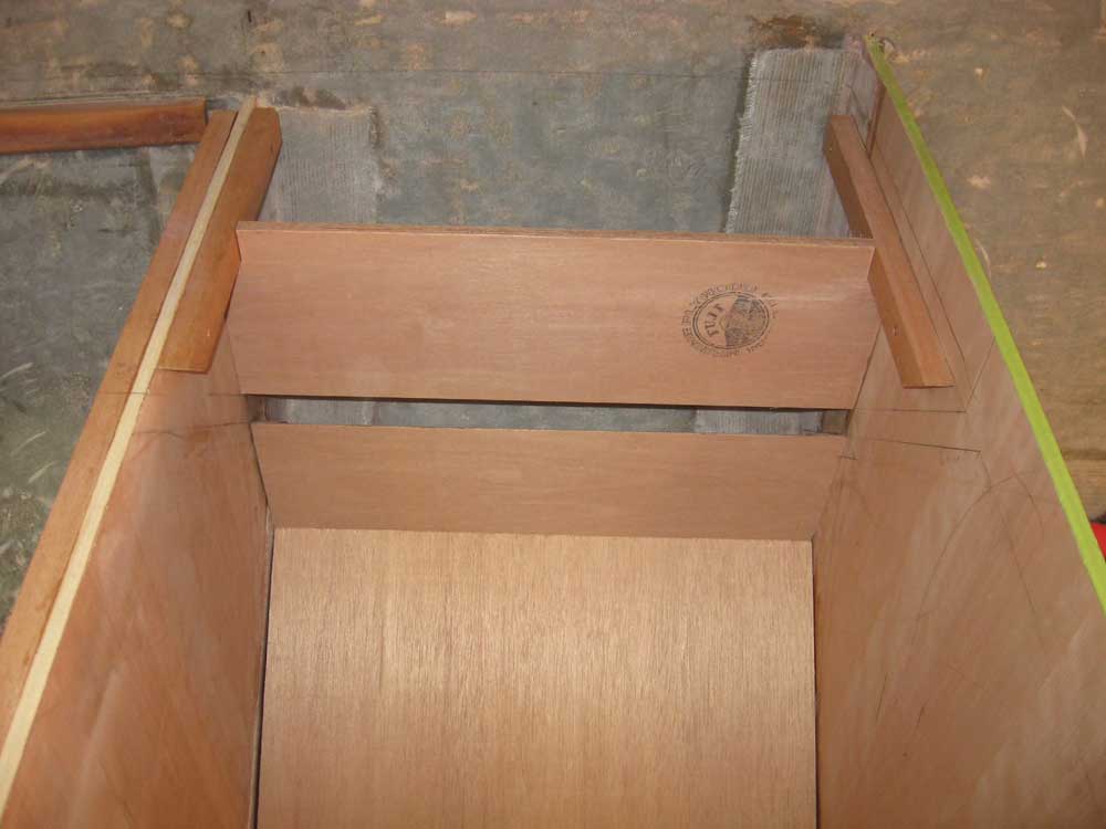
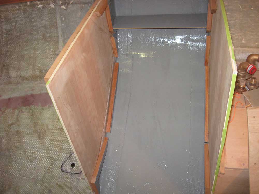
During the intervening portion of the afternoon, I finished up the "behind the scenes" work required in the stove enclosure: I installed a small shelf in the aft portion that would form the bottom of a storage locker accessed through the countertop behind the stove, and cut and fit the two plywood sections required to form the back of the cabinet, on either side of the slot through which the stove cover would slip. |
  |
|
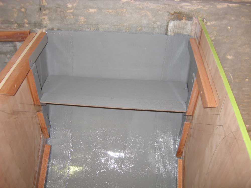
Before permanently installing the back panels, however, I took the opportunity to paint the hull and cabinets in areas where it might not be accessible in the near future. Most of this area would never be seen once the cabinet was complete, but I still liked to painted it out. |
 |
|
|
|