| Circe
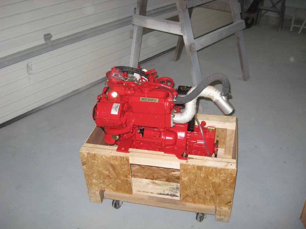
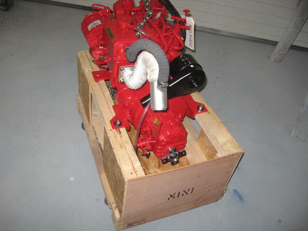
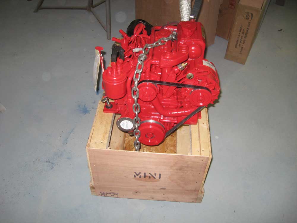
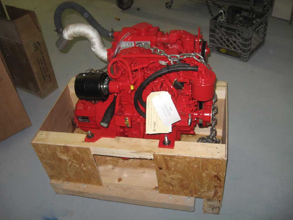
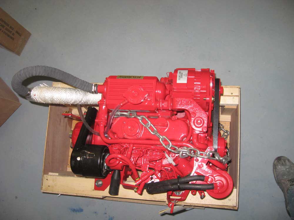
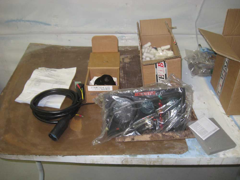
| Monday, November 16, 2009 I drove to the shipping depot where the engine had been deposited, and brought it back to the shop. I unloaded and inspected the engine and its related components, and then set it briefly aside while I turned to a number of the projects that were currently underway, which I hoped to more or less wrap up before I focused on the engine installation--though I was looking forward to getting the engine work underway as soon as possible. The engine is a Beta 20 3-cylinder diesel. |
|
|
|
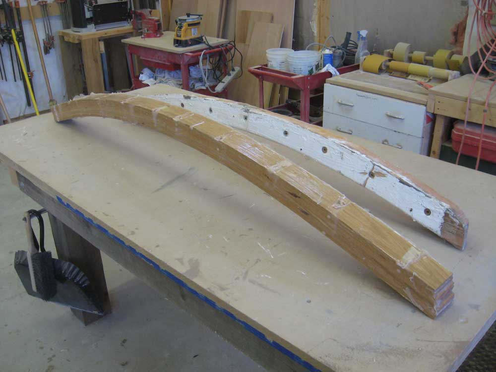
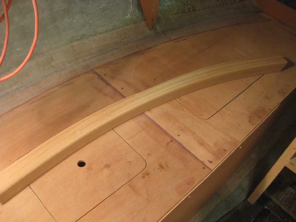
I removed the mast beam from the clamps, cleaned off some excess epoxy, and sanded one side smooth enough to allow passage through my planer. Then, I planed both surfaces of the beam smooth and flat, removing slight variations in the board thickness and excess epoxy from the lamination. Once both sides were smooth, I sanded the top and bottom faces to clean them up. |
 |
|
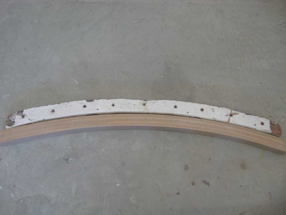
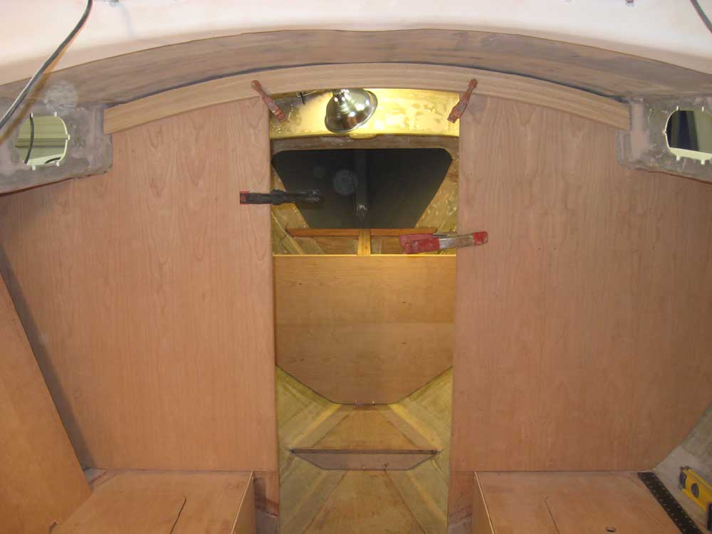
Next, I used the old beam as a guide to cut the new one roughly to the correct length. Then, I made adjustments as needed to get the new beam to fit in its designated space. I temporarily clamped the 1/4" cherry veneer in place so that the beam would be in its correct position. The center portion of the deck had an area of extra reinforcement that bulged downward, meaning that there was essentially a flat section required in the arch. I'd purposefully laminated the new beam in a clean arc so that I could scribe this area accurately, and that was my next step. With the beam clamped in position and "level" according to my eye, I used a scribe to mark the area in the center where I'd need to remove some material, and then sanded to my marks with a belt sander, stopping short of the marks on the first go-round to check the fit before continuing. |
 |
|
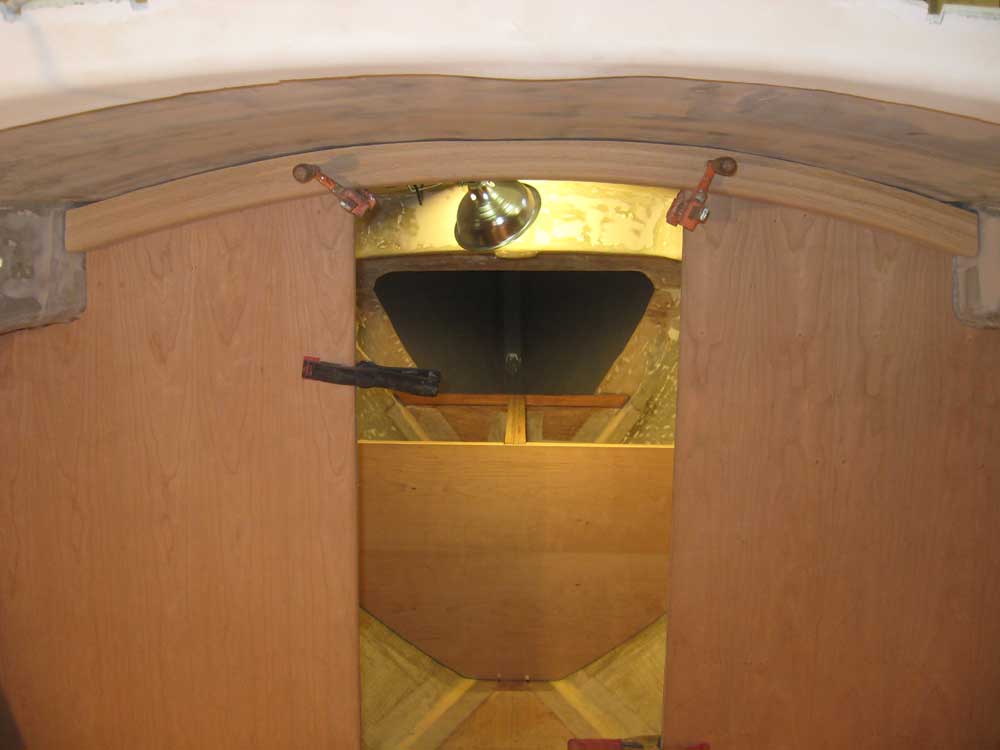
With the center portion sanded down to fit relatively closely, the general shape of the overhead prohibited a perfect fit all along the length of the beam. Rather than attempt to shape the beam to fit, I decided to fill the unevenness with an epoxy mixture, using the beam as its own mold. I'd do this in a day or two, once the cherry bulkhead veneer was permanently installed. For now, the beam was the right size and shape, and I finished up basic preparations by rounding over the exposed after corner with a wide radius bit and then sanding the beam smooth. |
 |
|
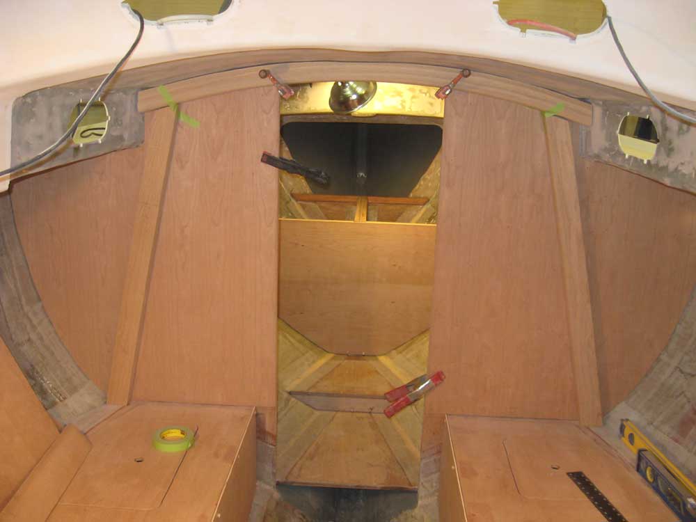
With the beam once again in place and clamped securely, I traced the bottom edge on the plywood beneath so I could begin to lay out the two pair of vertical compression posts. After removing the beam once more, I made some layout marks. The two posts near the centerline would be straightforward, extending straight down directly on either side of the passageway. Further outboard, two additional posts would be required, and I planned to roughly emulate what had been in place originally. I landed the outboard beams on the settee right at the corner where it met the hull, and then laid out angled lines up to the position of the mast beam. With the angle set on my bevel gauge, I cut blanks slightly overlong, and then trimmed them to match the layout line at the bottom of the mast beam arc. I repeated this process on both sides. Here, the green tape is helping hold the angled beams in position for illustrative purposes, though gravity dictated that the posts slipped somewhat and aren't necessarily in their final positions. |
 |
|
Tomorrow, I'd build the two center posts, and wrap up the milling and sanding work on all four posts. Then, I could permanently install the cherry veneer on the main bulkhead, since I could use the areas beneath the eventual posts for screws to hold the panels in position while the adhesive cured, which was why I chose to work on these posts at this time. Several other finish and trim jobs in the main cabin were pending that required the final bulkhead surface to be in place. |
|
|
|