| Circe
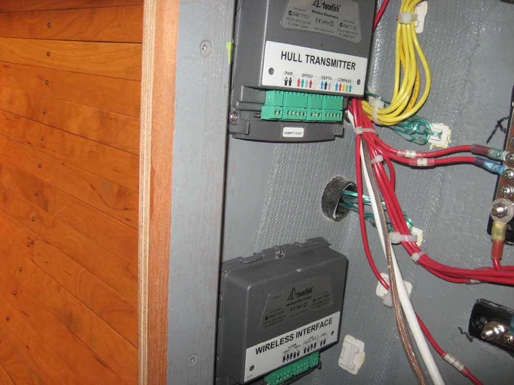
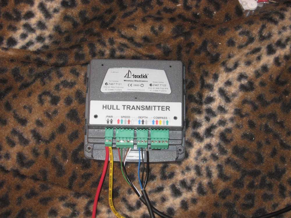
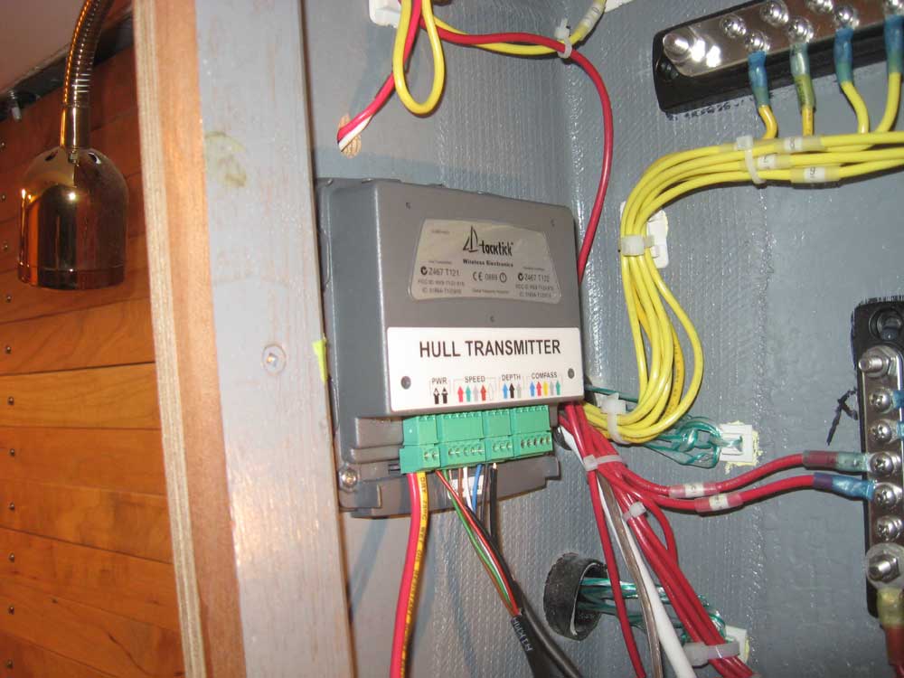
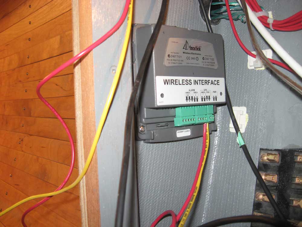
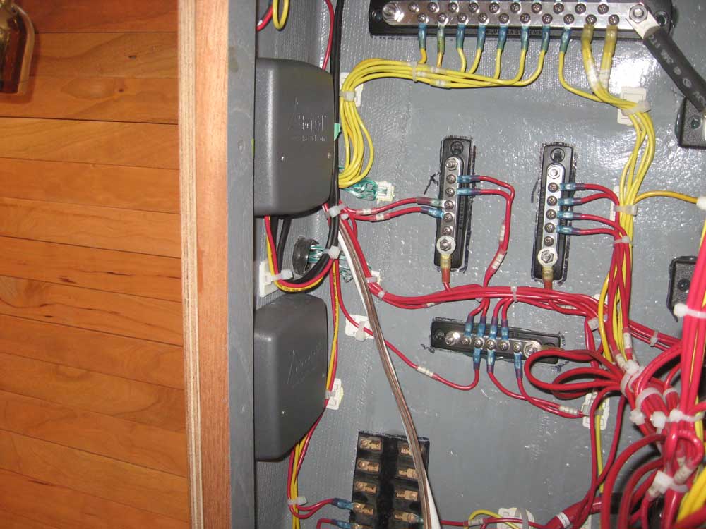
| Tuesday, March 23, 2010 The owner chose to install a full complement of sailing instruments by TackTick, which feature wireless instrument heads and masthead wind anemometer that streamline installation and offer versatile mounting and usage characteristics. The instrument heads and masthead unit feature solar power and wireless technology for their data streams. Earlier, I'd ordered the system, and had had it on hand for a few days. Now, I turned to its installation. The system wasn't truly and completely wireless, of course: transducers for speed and depth required a wired connection to what TackTick calls a hull transmitter, which also required a 12V power supply. Similarly, a separate wireless interface unit, which sends the wireless data to the instrument heads, also required a 12V power supply. The directions indicated that the wireless interface was best installed on a transverse, rather than longitudinal, surface. This offered limited options in this boat, but fortunately there was the perfect amount of space on the inside of the forward bulkhead (transverse) defining the electrical locker, which was about an ideal location for many other reasons as well. After poring over the contents of the box and the various installation sheets, I mounted the two units in this space. |
|
|
|
I installed the speed/temp and depth transducers in the hull beneath the starboard aft settee, and ran the cables around and into the electrical locker, where I made up the connections to the hull transmitter as required. To make this easier, since access was awkward with the unit installed in the tight space, I actually removed the transmitter to make the connections, though I discovered later that the little wiring connectors in the unit actually pulled out separately; therefore, I simply removed the small plug for the power supply to the wireless interface to make up the positive and negative connections there. Once I'd made the various connections (which was easy and straightforward despite my initial negative impressions of the teeny-tiny screws and clamps provided for the wiring connection), I reinstalled the hull transmitter on the bulkhead. |
 |
|
Next, I made up the wiring connections for the power supplies. The hull transmitter required a 1A fuse; no fuse was called for in the wireless interface connection, but since both units would share a single circuit, I interconnected the two positive supply wires at the nearby fuse block, where I'd install a 1A fuse later (on order). I connected the two negative wires to one of the negative distribution busses on the back of the electrical panel, since the large buss was full and in any event it was a clean, easy run for these wires to the panel itself. Finally, I ran a positive wire from the opposite side of the fuse block to the appropriate circuit breaker on the panel, tied up the excess transducer cable, and installed the covers over the TackTick units. |
 |
|
One benefit of the wireless instrument heads, other than saving the chore of wiring each unit and drilling mounting/wiring holes in the bulkhead, was that they could be mounted in such a way as to be easily removable. Therefore, I didn't even proceed with considering their installation for now, since it was likely we'd end up using hook-and-loop to attach the instrument heads in a location of the owner's choosing later. There were two instrument heads provided: one for the speed and depth, and a separate one for the wind information. I'd install the masthead unit for the wind instruments later, when I got around to some of the other mast work that needed to be done. |
|
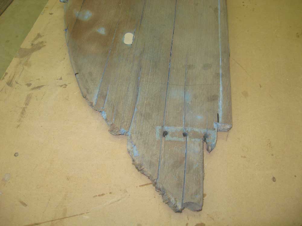
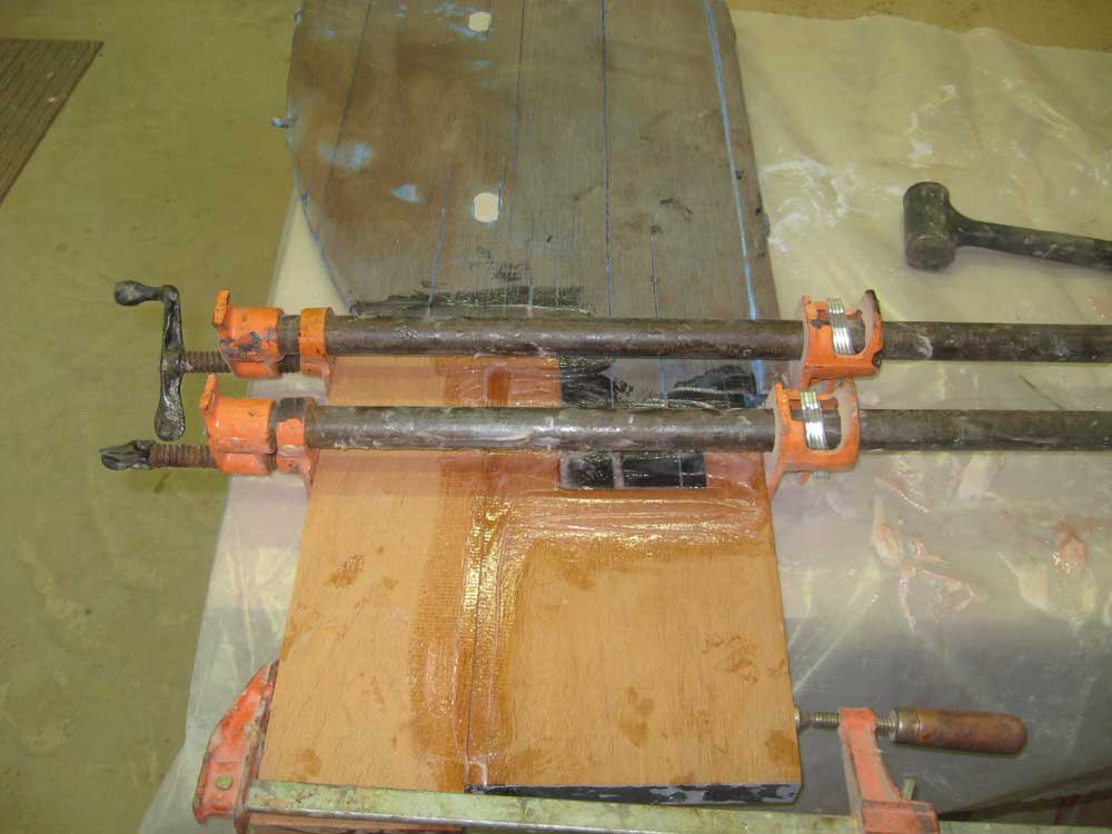
The afternoon was a mishmash of smaller and nondescript tasks. Among these was a small repair to the lower tip of the rudder, which had been minimally chewed up at some point in the past. Since the rudder was in serviceable condition otherwise, I chose to make some squared-off cuts and replace the damaged area with new mahogany epoxied to the base of the rudder. The arena in which I made the cuts also ensured that the new section would be partially secured by one of the three bolts securing the lower pintle for additional strength, but given the nature of the repair and the area of the rudder which was affected, I wasn't concerned with strength. I cut new pieces of 5/4 mahogany as needed and glued them in place; once the epoxy cured, I'd trim the repair to the proper shape, after which I could proceed with the rudder reinstallation. |
 |
|
The lazarette hatch was done and ready for installation, so I installed a pair of stainless hatch hinges to the hatch and deck, bedding the hardware to the deck in the usual way. |
 |
|
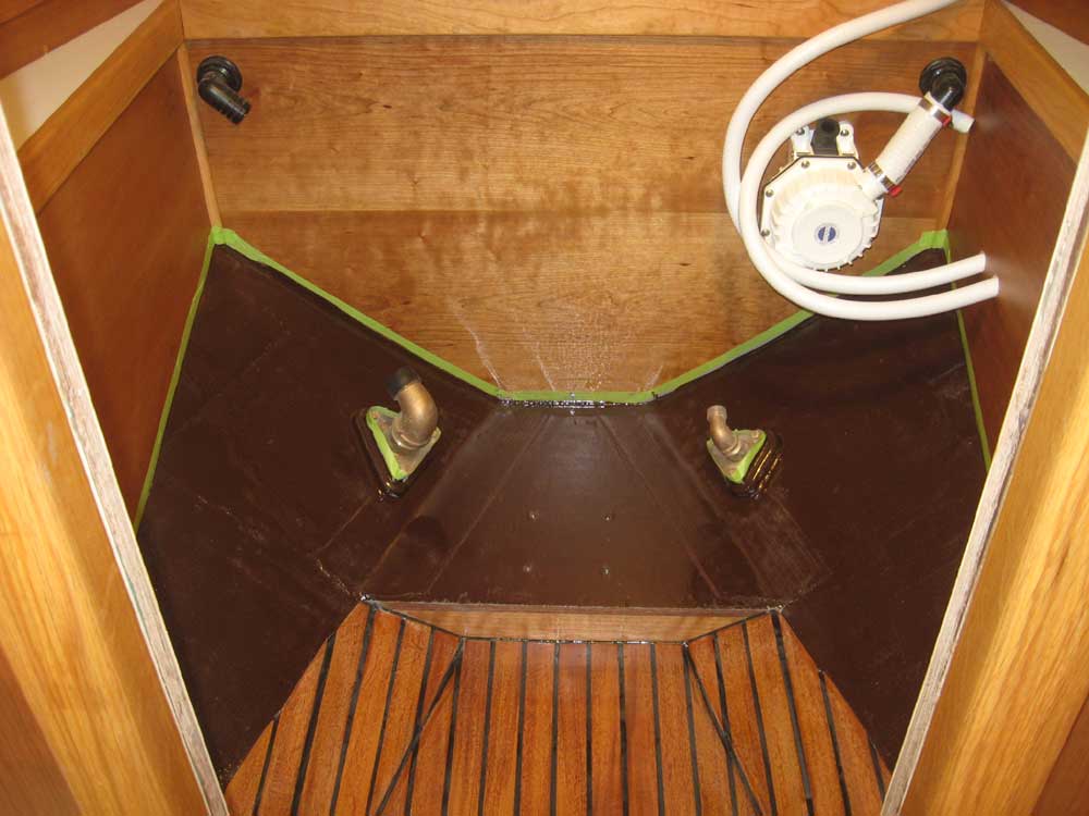
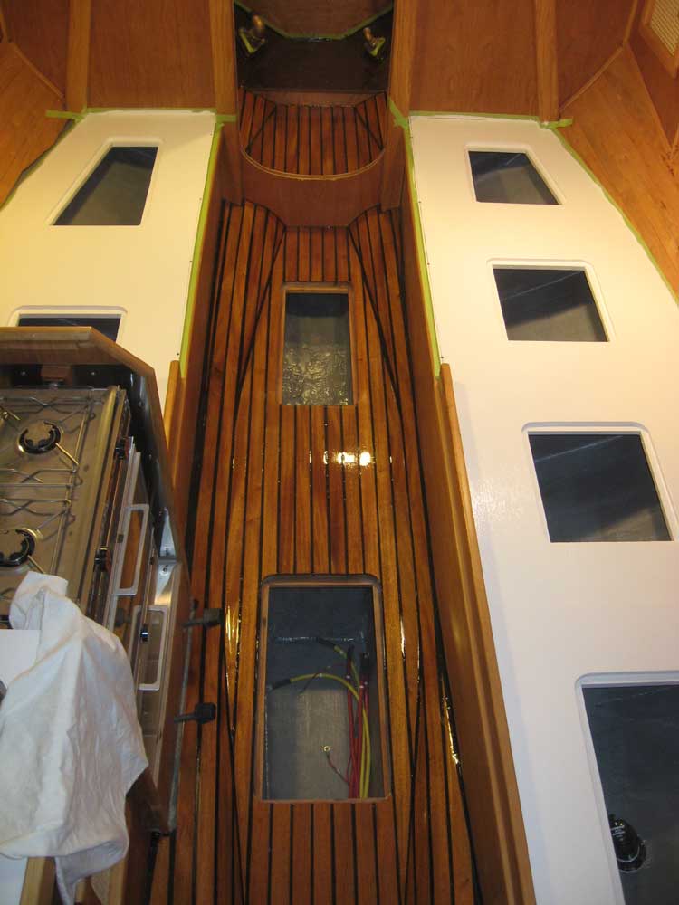
To round out the day, I applied a coat of brown paint to the exposed hull areas in the head compartment, repainted the settees and hatches with another coat of semi-gloss white, and varnished the cabin sole and various other trim pieces. |
  |
|
|
|