| Circe
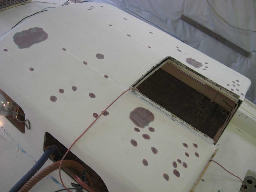
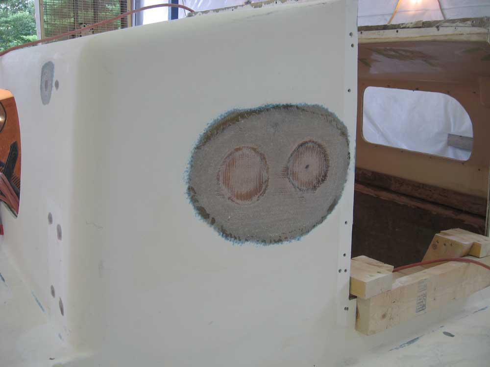
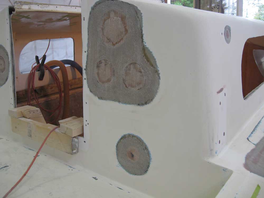
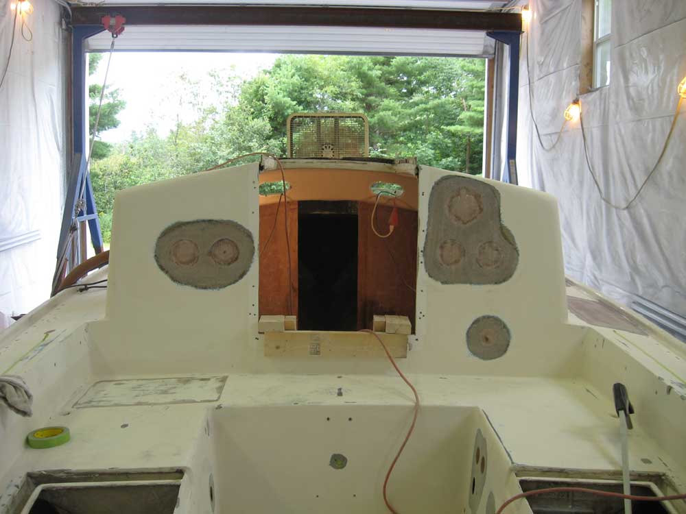
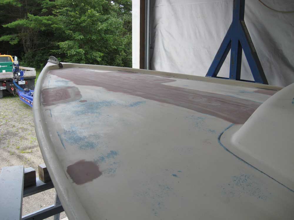
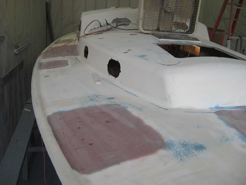
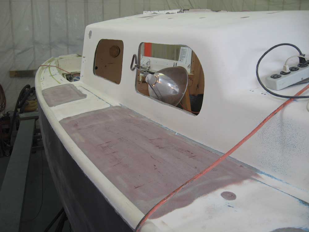
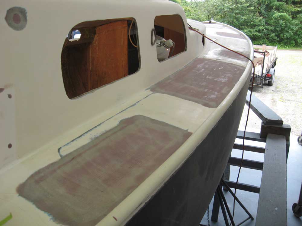
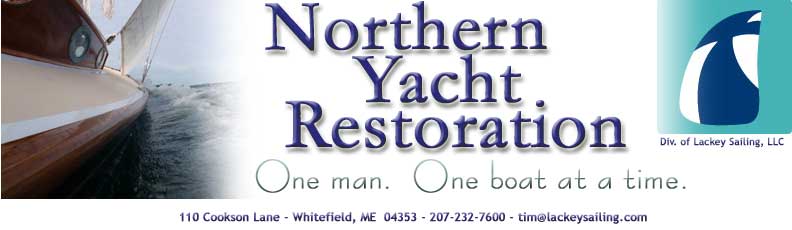
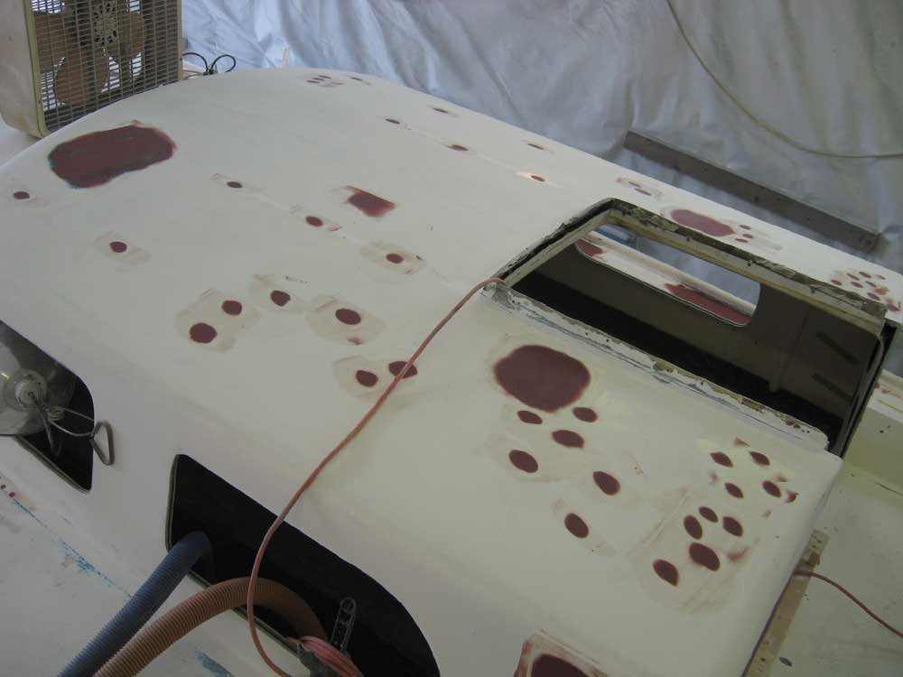
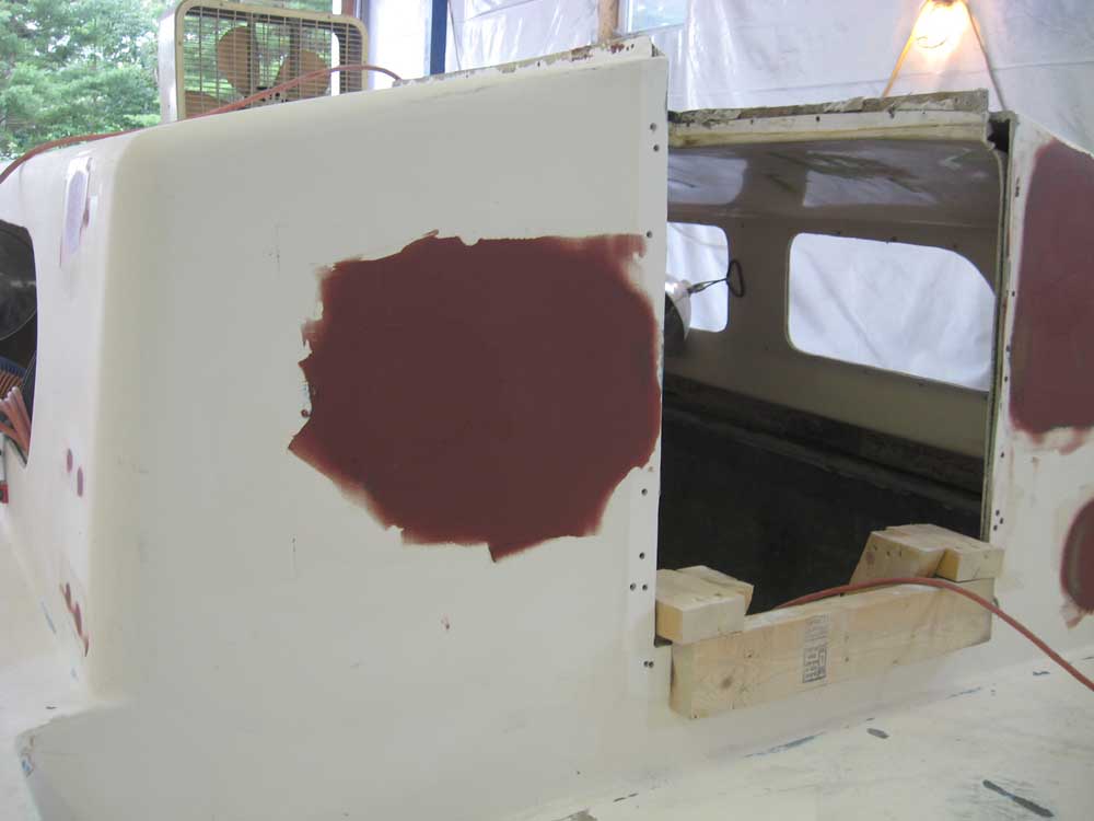
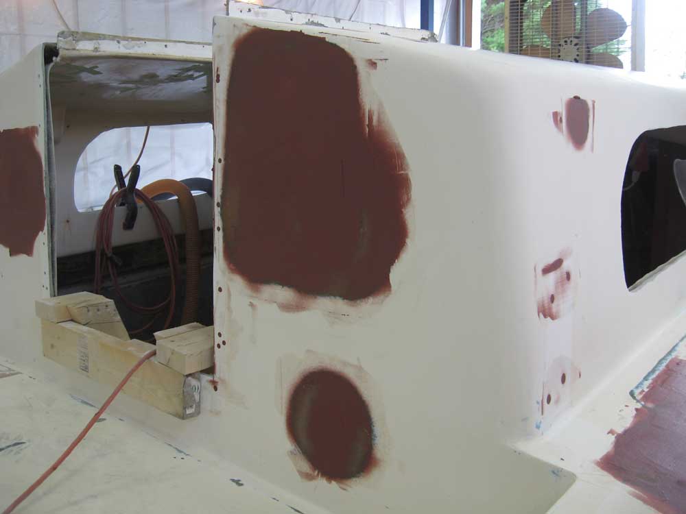
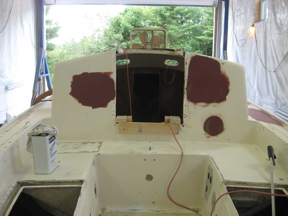
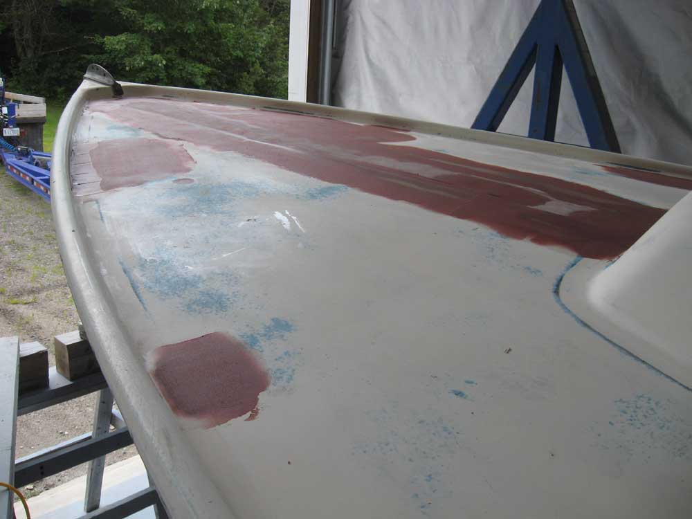
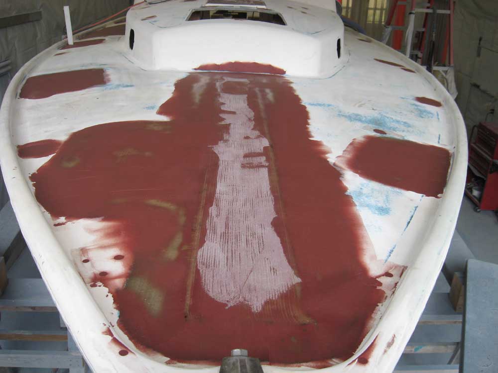
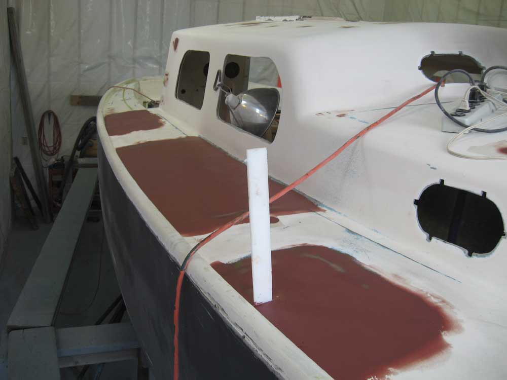
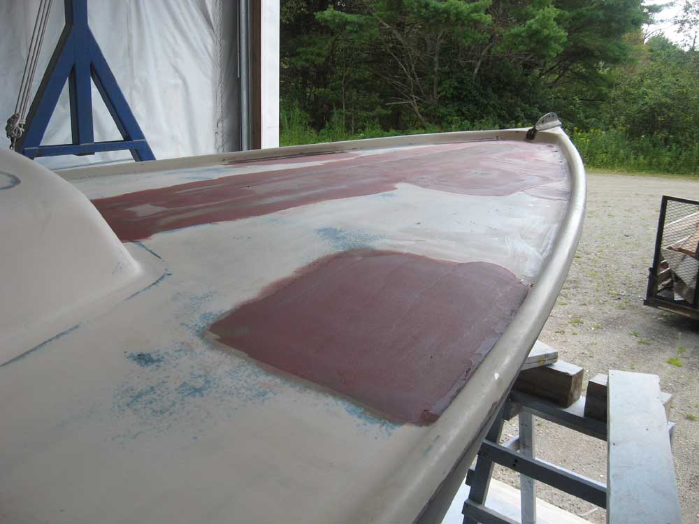
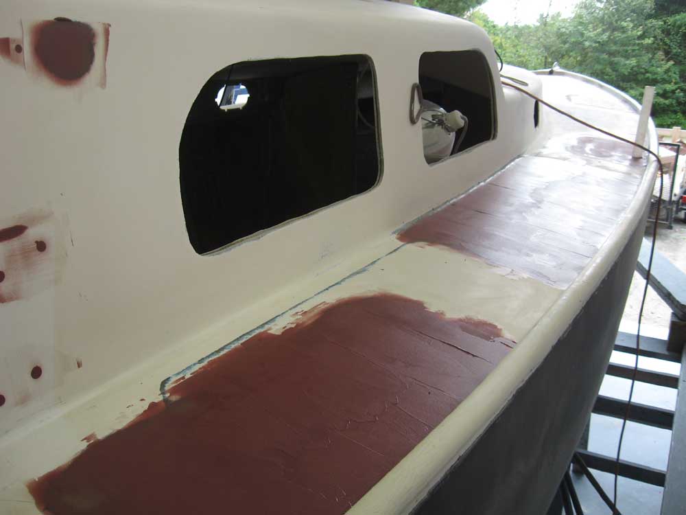
| Tuesday, August 11, 2009 Once again, I began the day by washing, drying and sanding yesterday's application of fairing filler and new fiberglass on the various portions of the deck. |
|
|
|
After vacuuming and solvent-washing, I continued the process by applying additional fairing filler to all areas, bringing me to mid-morning. |
 |
|
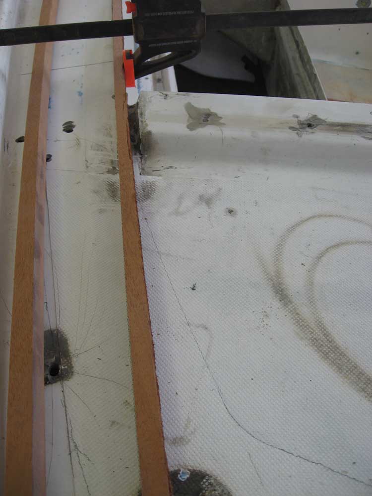
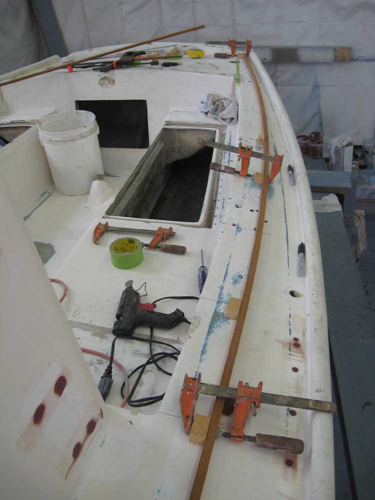
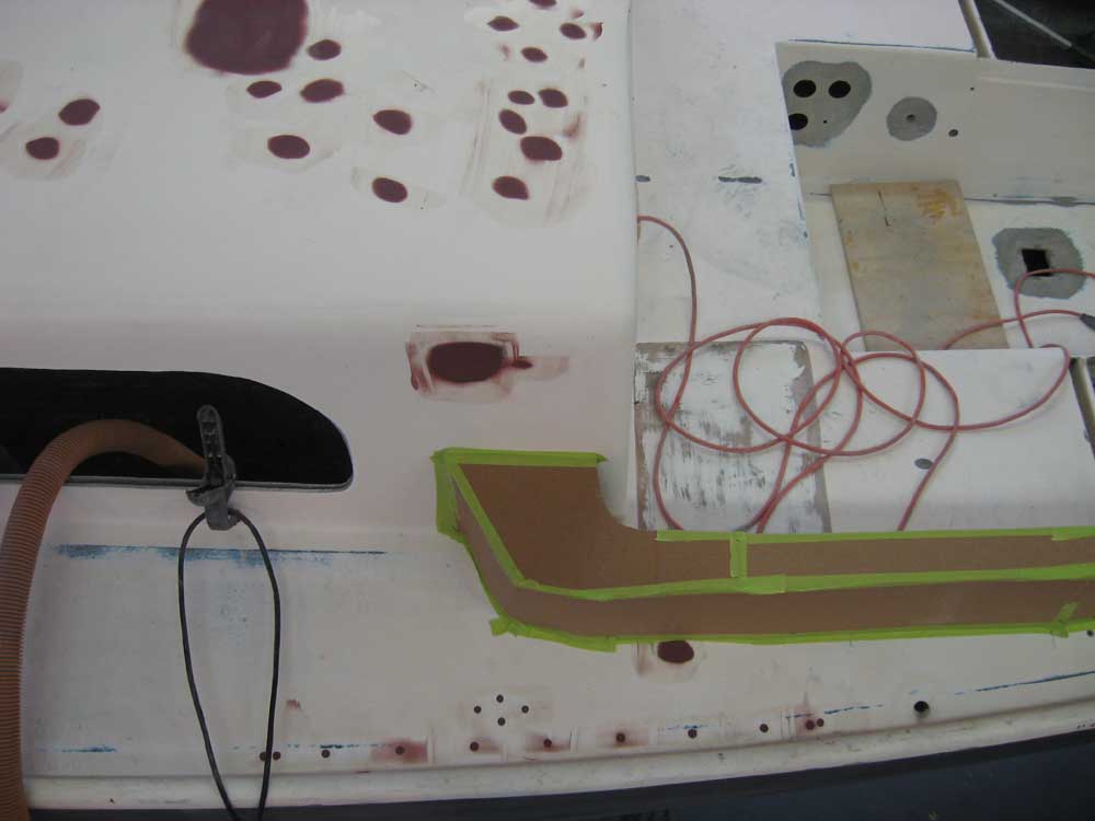
I had a meeting that consumed the rest of the morning, but afterwards I got to work on the proposed cockpit coaming mockups. Yesterday's brief exercise in layout had provided me with useful information, and with this in mind I began some more precise layout. To begin, I used a wooden batten to extend the line of the existing cockpit opening aft in a pleasing and fair curve that was a natural continuation of the existing opening. I clamped the batten to the inside of the existing opening and drew in the line after aligning the batten by eye. |
 |
|
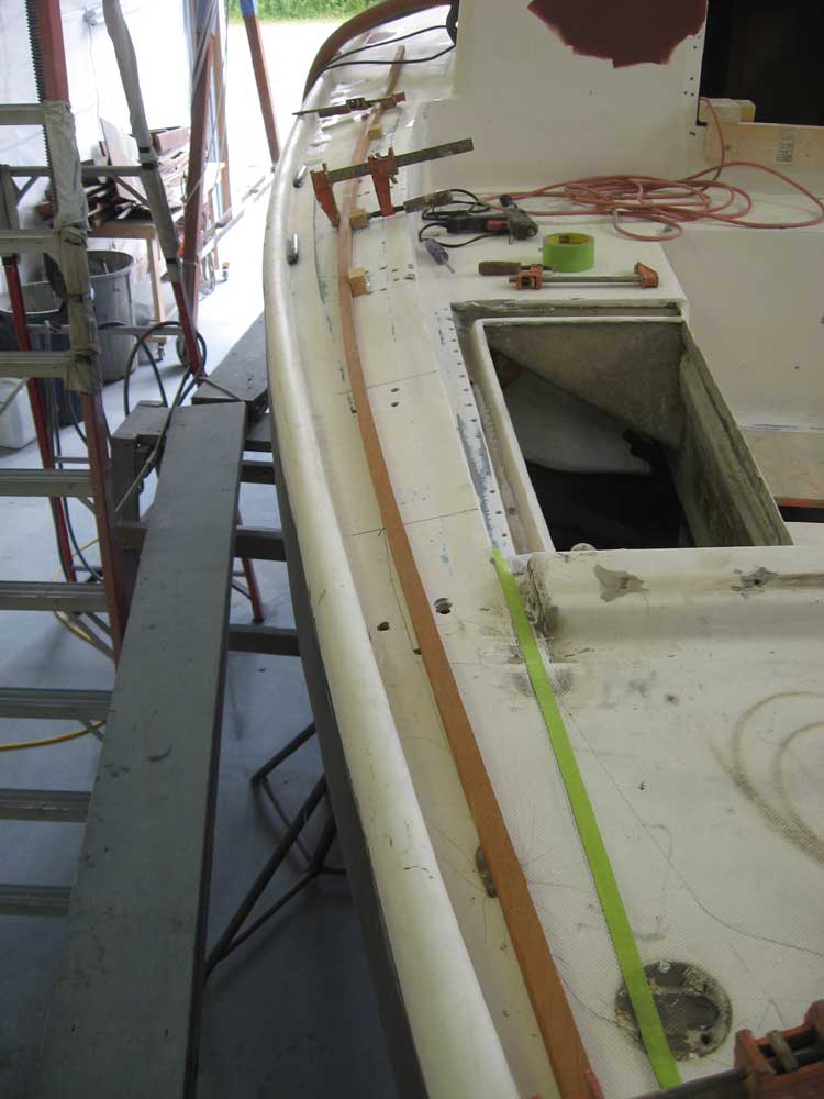
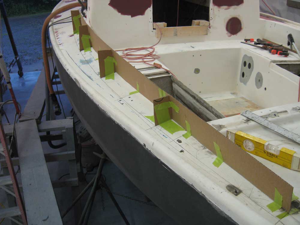
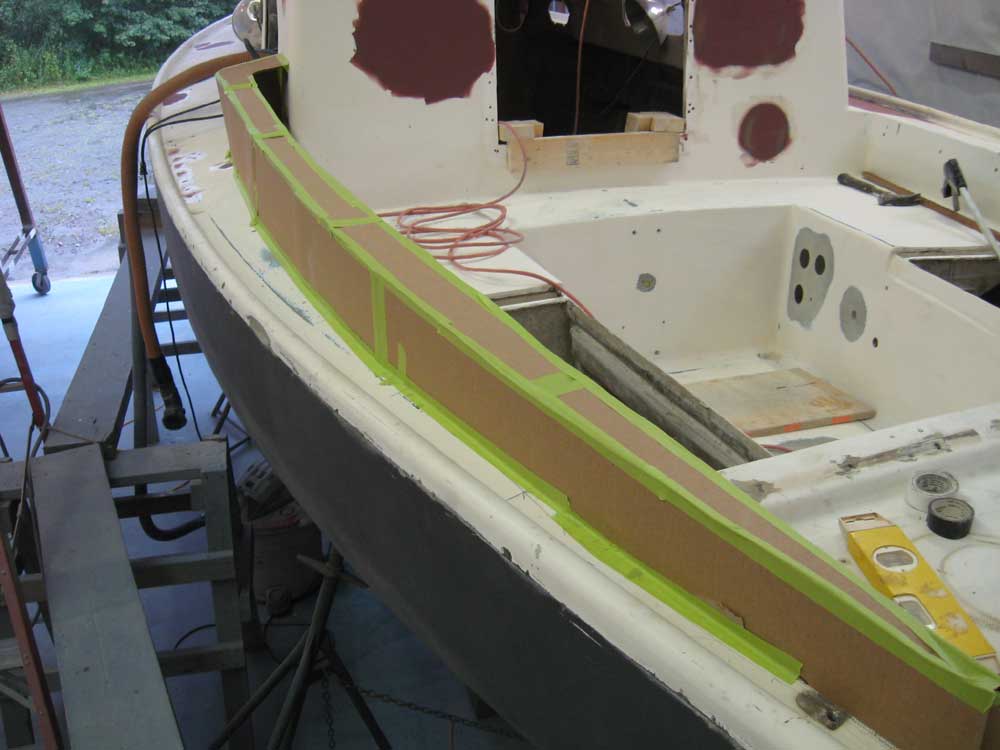
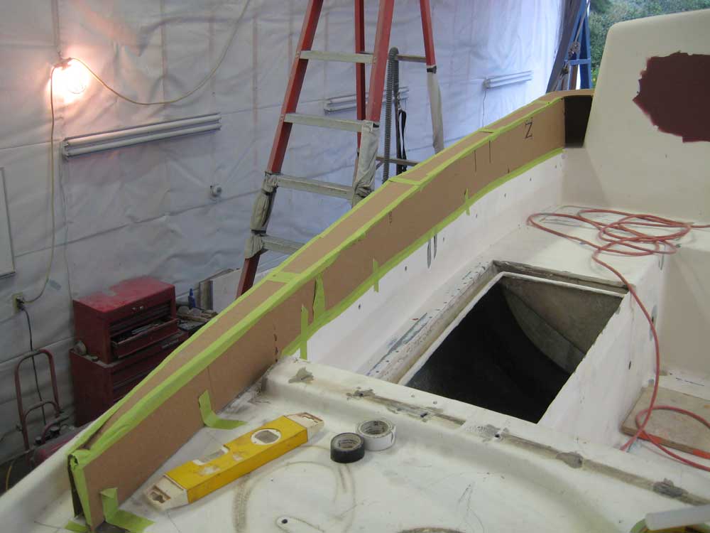
Similarly, I used a longer batten to lay out and define the outer edge of the coamings. My initial layout yesterday had shown a requirement to taper the width of the coaming as it headed aft, but I wanted to keep the maximum width as far aft as I could while retaining aesthetic requirements. I made a series of layout/station marks along the edge of the cockpit to provide me with static reference points from side to side, and hot-glued some small blocks to the deck, against which I could clamp the batten. After determining the after extent of the full width of the coaming and securing the batten to that point, I bent the batten further in at the aft end till the curve appeared pleasing and appropriate, while retaining sufficient width at the after end. I clamped the batten in this position and traced the line. In these photos, the inside edge of the batten defines the proposed coaming location. |
 |
|
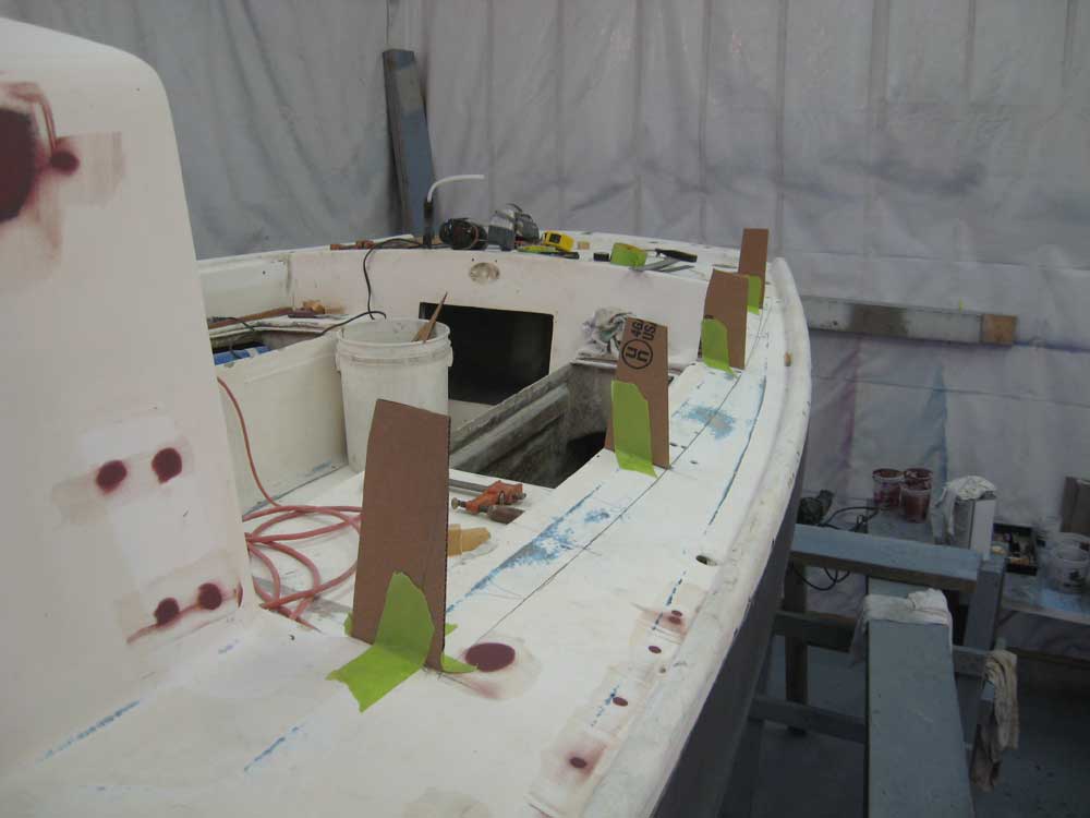
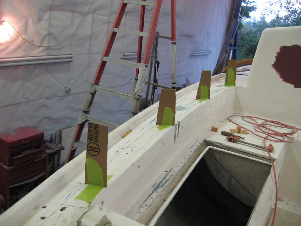
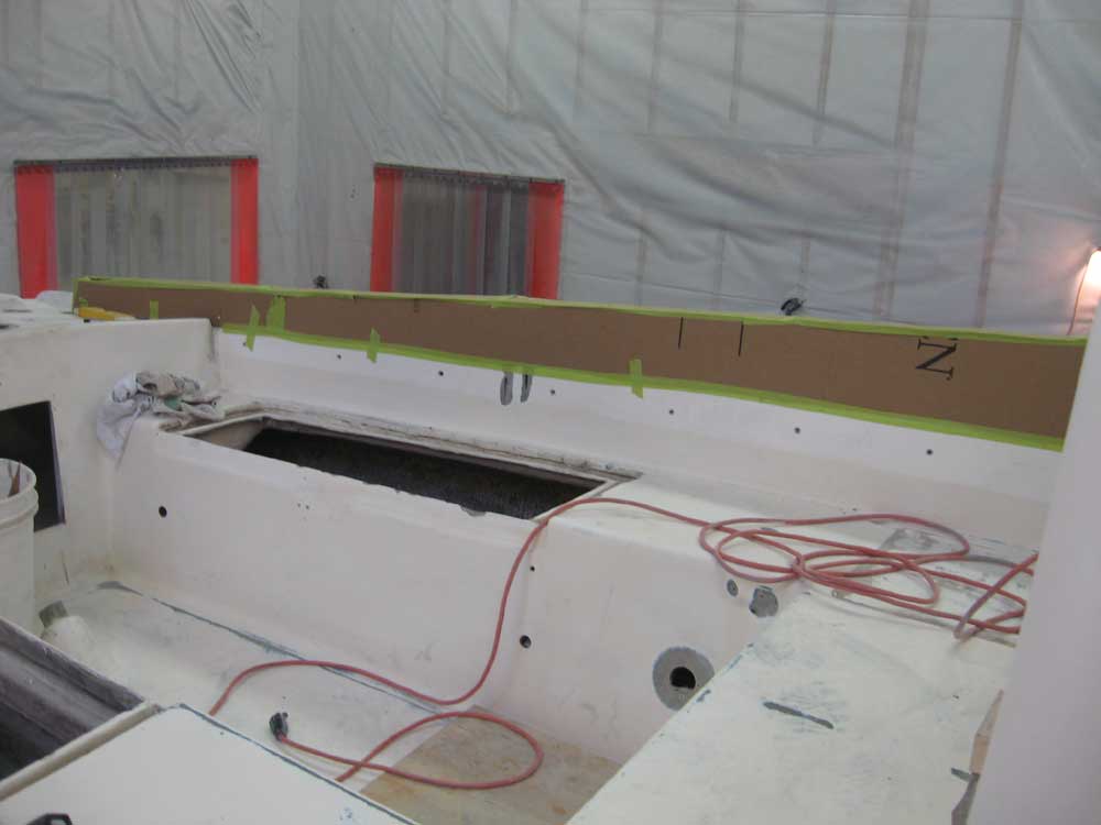
I transferred measurements as needed to the starboard side of the boat and, after removing the protruding fuel tank fill molding that was in the way of the batten, laid out the curves on the starboard side, since once I began the actual mockup to port, I'd lose the ability to easily make these measurements. Using "Whitefield mahogany" (scrap cardboard), I created a series of supports, located evenly along the length of the coaming at my pre-determined station marks, to define the shape of the new coaming. On the inside edge, I continued the line of the existing cockpit opening; at the outside, I roughly re-created the angle formed between the deck and the cabin trunk, which angled slightly towards centerline from vertical. This angle, in the ultimate coaming, would be subject to fine-tuning, but in any event had to be inclined slightly inwards for best appearance and functionality. |
 |
|
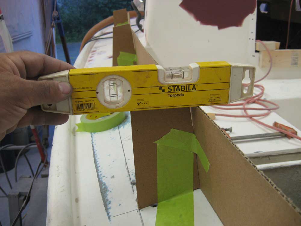
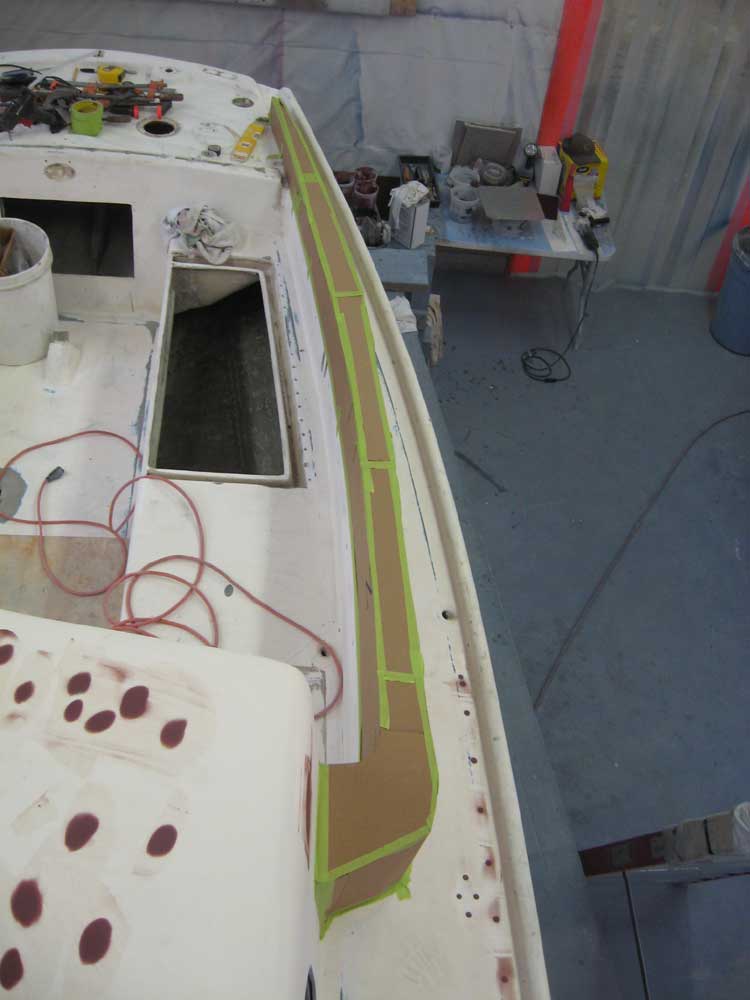
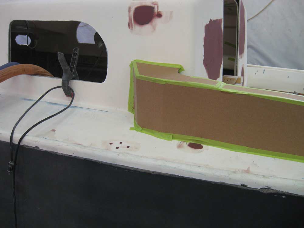
With the basics in place, I cut some additional pieces of cardboard to create the sides and top of the new coaming. Using the basic proportions of the original wooden coamings as a guide, I first cut the inside piece, which would in turn define the height of the outside. The original coamings extended 7-1/2" above the deck edge at the forward end, and about 3" above at the after end, so as a starting point I used these measurements. I taped the inner side of the coaming in place, and then used a level to mark cut off the excess height on the vertical supports, figuring that the top of the coaming ought to be basically level, at least for the moment. I had basically leveled the boat when I set it in the shop some weeks ago, and knew that for my current purposes things were level enough. Later, before I began any real construction, I'd ensure that the boat was perfectly positioned in both directions to ensure that my layout was accurate. |
 |
|
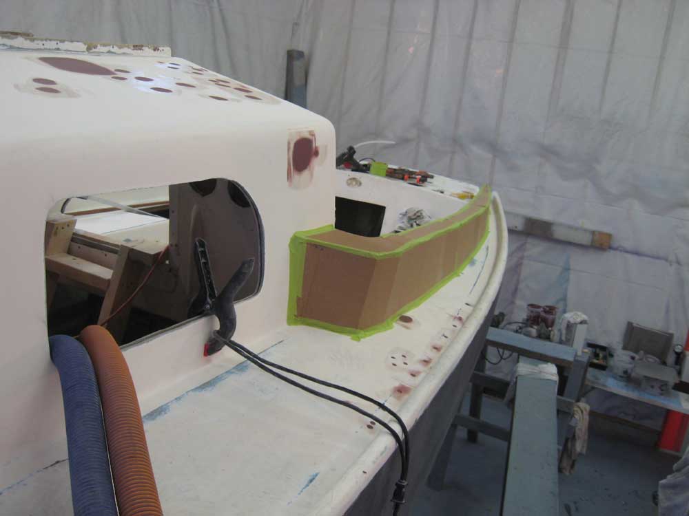
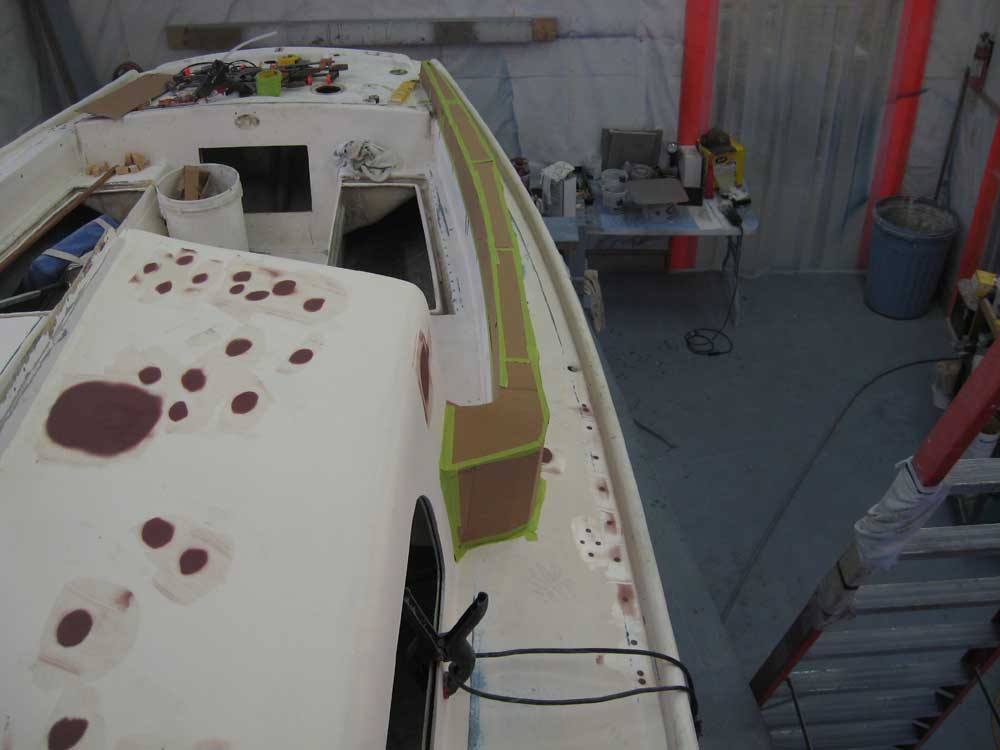
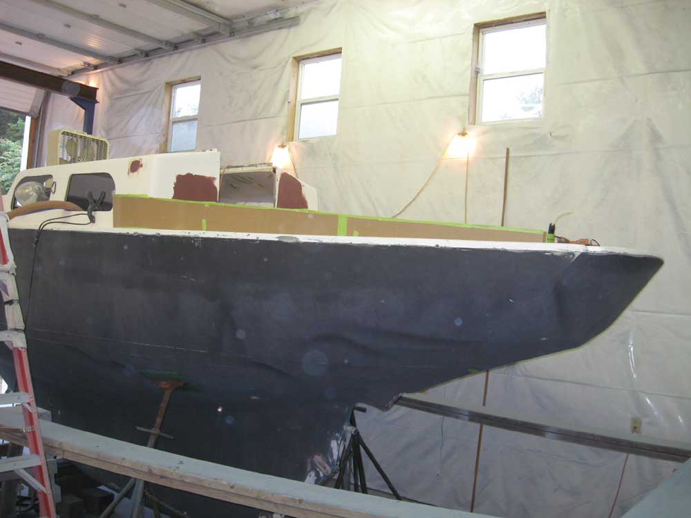
Next, I cut the outer edge of the coaming, taped and glued it in place, and then installed a top piece, including a return at the forward end. Note that there are significant limitations to the use of cardboard for this purpose, and that the idea of the mockup is not to define exact curvature and shapeliness, but rather to convey the overall dimensions, proportions, and appearance/functionality of the proposed coamings. The mockup was necessarily rough, but provided some idea of how these new coamings might work and feel on the boat. |
  |
|
My initial thoughts after creating the mockup on the port side were that perhaps it was a bit tall; I thought I might see about creating a similar shape, but slightly lower on the starboard side mockup. Of course, since the coamings provide the backrest and protection for the cockpit, they require a certain height to remain functional; still, I thought there might be an opportunity to reduce the height while retaining proper ergonomics. Also, determining the exact contours and size of the forward returns would be critical when it came time for actual construction, to eliminate unnecessary bulkiness and to ensure that the coamings appeared to be a natural, sweeping extension from the cabin trunk. The angle I created between the outer edge of the coaming and the deck would also require tweaking in the real version, though as a starting point the initial shaping (within the extreme limitations of the cardboard) was generally what I'd been envisioning. Providing the proper tapered and angled contours of the basic coaming shape also limited the width at the top edge, though I made all efforts to minimize this. I envisioned a wooden caprail to cover the top of the coaming, which could extend slightly on the outer side (I'd planned a 1/2" overhang during the layout stage), so the top would be somewhat wider than shown; still, I thought the coaming top was probably wide enough to allow for seating if desired, though somewhat narrower than the original specification of 4" minimum (I'd used 3-1/2" to lay out the overall coaming width based on this specification, anticipating 1/2" overhang for the wooden caprail and keeping the confines of the actual deck width in mind, forcing a compromise as the coaming tapered both in a vertical direction and as it proceeded aft). And of course, the real coaming would require an appropriately-shaped pad on which to secure genoa sheet winches, but their exact location would depend on the winches chosen as well as the position of the steering pedestal, as well as whatever limitations the width of the remaining sidedecks would impose. I thought I'd try and bring some of these initial thoughts to life on the starboard coaming mockup, which I'd work on next. |
|
|
|