| Bolero
Project |
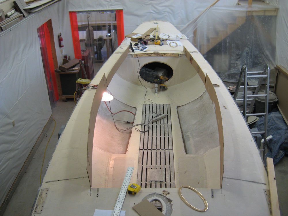
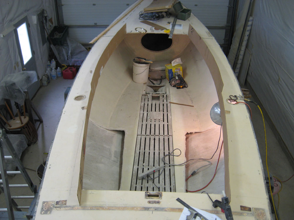
November 19, 2007 With many decisions regarding the eventual execution of the boat--particularly her interior design and layout--hinging upon the size and shape of the planned cabin trunk, it was time to create a mockup so that the actual confines of the space available would become more readily apparent. So, armed with a basic, roughly-scaled drawing labeled with a few key measurements (the same basic measurements I used to lay out and cut the overall cockpit opening last week), I set out to create a cardboard mockup of the cabin trunk. While the drawing and its measurements were not cast in stone, the overall concept was quite successful, and seemed to be a good point from which to start. Typically, though, the realities of the various factors at hand would require some basic modifications, however. This was to prove to be the case. I cut some cardboard into appropriately wide strips for the anticipated height of the mockup, and used a hot glue gun to attach the cardboard to the inner edge of the deck cutout. I made the forward section taller than the aft section, but the junction between them does not signify the actual location of the transition between cabin trunk and cockpit coaming; later, this will all become more clear. |
|
|
|
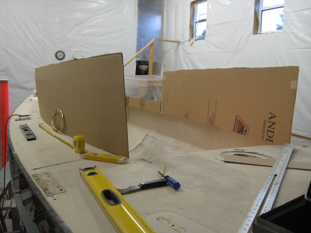
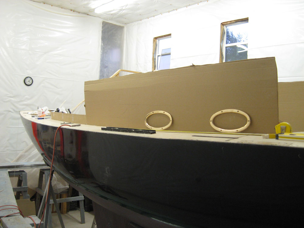
As I began to consider the actual layout, however, I realized that the cardboard I'd cut for the cabin trunk was not going to be tall enough at the aft end, so I had to remove the first pieces and replace them with taller ones. This time, I let the cardboard height soar well above the actual height of the cabin trunk; don't let this pilothouse-sized cardboard fool you. |
|
|
|
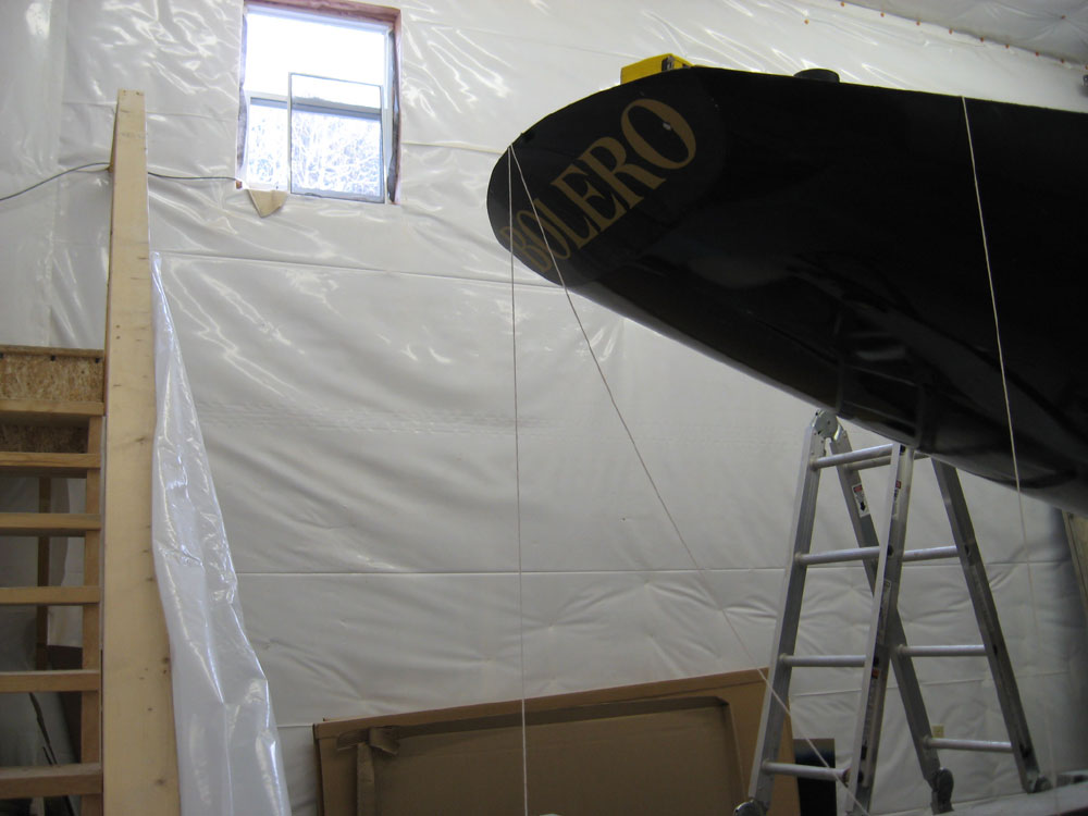
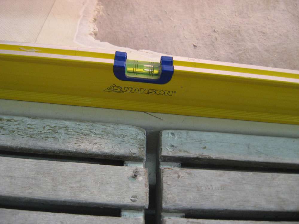
Consulting the drawing, I confirmed--or at least was pretty sure--that the top edge of the cabin trunk sides shown were intended to be parallel to the designed waterline (DWL) of the boat. Lacking enough size and detail to accurately scale off the drawing, and without specific measurements to work from, I realized I had to confirm that the boat was level in a longitudinal (fore and aft) direction, since to lay out the cabin trunk line I needed to use a level (since I had no accurate measurements from which to work). I had quickly leveled the trailer when I set the boat in the shop, but I needed a means of confirming that the boat itself was level. I thought the cockpit sole might be parallel with the waterline, but couldn't find any information to support this notion and didn't want to rely on this. Fortunately, I discovered that the owner's research had located a fairly large-scale lines drawing of the Shields, and while this drawing did not contain a depiction of the cockpit sole, it did provide freeboard measurements to the DWL at bow and stern. Using these measurements--or more specifically the difference between the measurements, which was 6-5/8"--I could level the boat off the shop floor according to the DWL. |
|
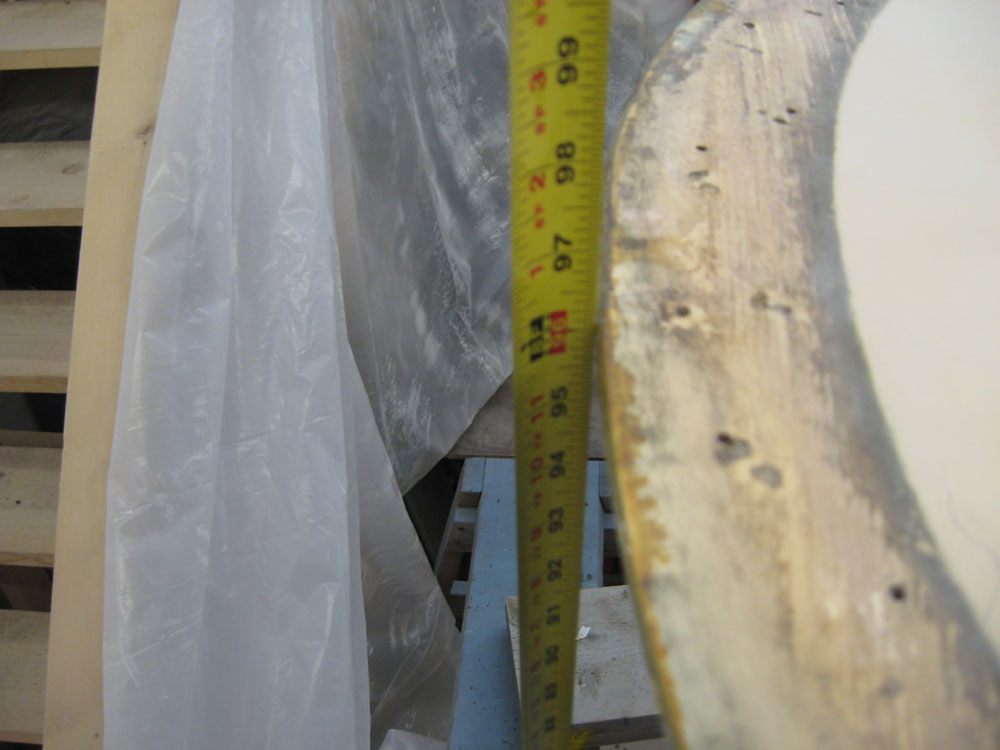
First, I used a plumb bob to transfer the stem and transom ends to the shop floor so that I could hold a tape measure in the proper location for the most accurate measurements. I measured the height of the stem and the stern and calculated the difference between the two. According to these measurements, the boat was off by 5/8"--the stern was too high. The measurement I wanted was 96-1/4" at the stern and 102-7/8" at the bow; what I had was 96-9/16" at the stern. |
|
|
|
To correct the 5/8" difference, I needed to raise the bow by 5/16", or half of the total difference; the stern would thusly go lower by 5/16" itself, correcting the overall height difference between bow and stern (off the floor) to the 6-5/8" required in order for the boat to be level according to its DWL. This was fairly straightforward, though it took a bit of fine tuning before I achieved the correct measurements bow and stern. The boat ended up within 1/8" of the appropriate measurements over its 30' length, which seemed accurate enough given the inaccuracy of the overall situation. |
|
|
|
With the boat now level according to the design drawing, I checked the cockpit sole to see where things ended up. On this particular boat, at least, the sole was not level with the waterline; it was off by a significant amount and wouldn't be an accurate gauge of the boat's level. |
|
|
|
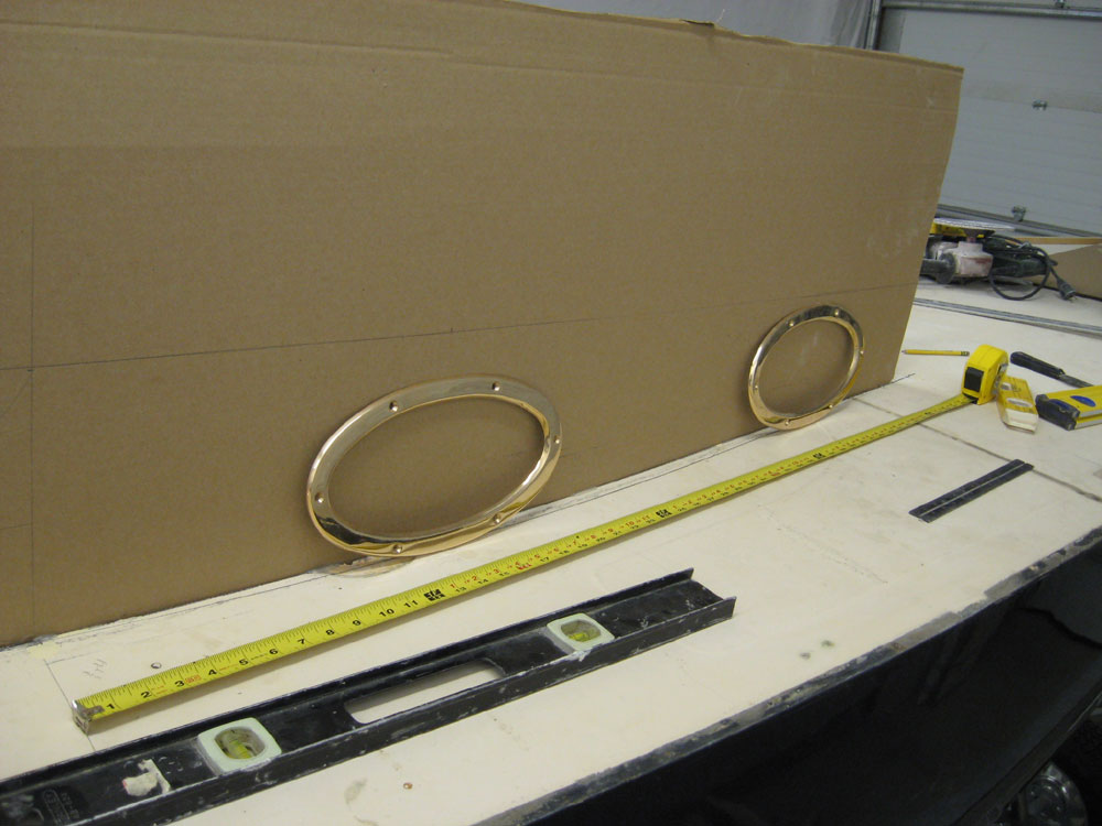
With the boat satisfactorily level now, I continued with the layout for the cabin trunk and coamings. There were many factors driving the design of this trunk, and as I began to lay things out I realized that the drawing I had was raising more questions than it was answering. For example, I wasn't sure the cabin trunk was accounting for any deck camber--which turned out to be significant, since the camber at the forward corner of the cabin trunk, over the 17" width of the side deck at that point, was 1-1/2"; at the aft end, it was about 1-1/4" for the 12" side deck width. Whether the cabin was depicted using the gunwale as a reference, or from the adjacent sidedeck could make a 1-1/2" difference in its height. Other factors that I had to consider as I laid this out included:
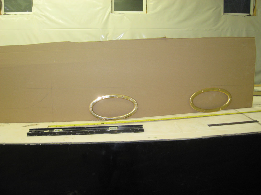
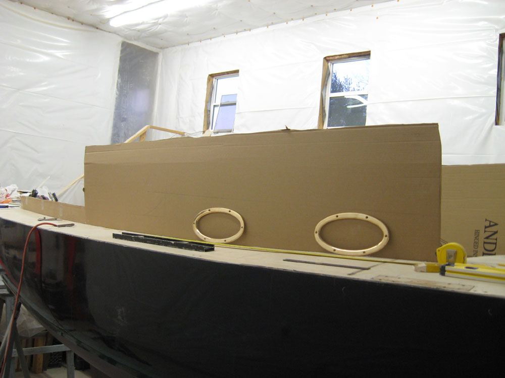
With these, and other, questions, I came to the conclusion that I needed some answers before committing to the layout I'd already sketched on the cardboard, so I took some time to discuss things in some detail with the owner by email and phone, effectively ending progress for the day but gaining me the knowledge I needed to continue with the mockup. This series of photos shows the state of the mockup at the end of the day, along with some of the port frames roughly mocked into position. Some pencil lines from my original layout are visible on the cardboard, but it's tough to visualize the shape of things to come just yet. Please ignore the tall height of the cardboard, which has no relevance to the actual shape being developed. |
|
|
|
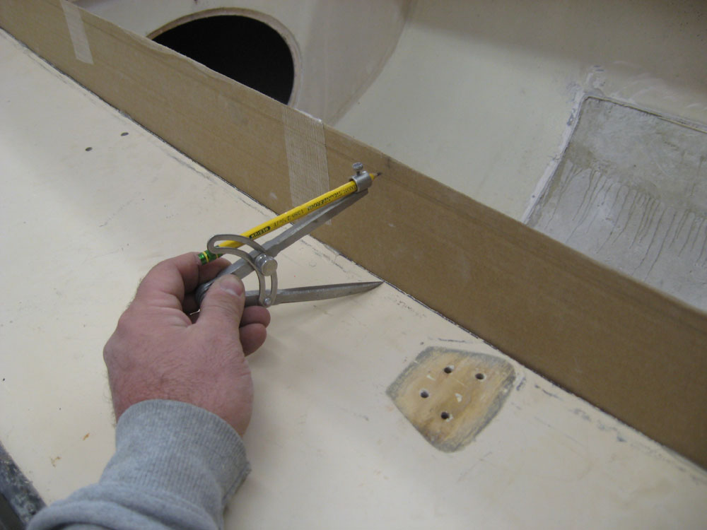
I used a compass to mark out a consistent 3-1/2" height for the new coamings aft of the cabin trunk, but it was clear to me that the coamings needed to taper in height as they ran aft, so I planned to abandon that line and strike a new one that would look more appropriate. |
|
|
|
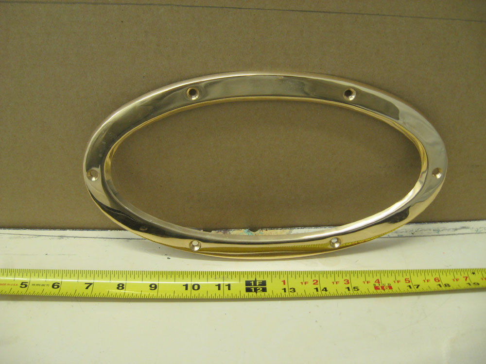
I roughed out a transitional curve between cabin trunk and coaming using one of the elliptical port frames as a template. |
|
|
|
I didn't get quite as far as I'd hoped today, but now had the information I needed to complete the mockup in the morning. |
|
|
|