| Bolero
Project |
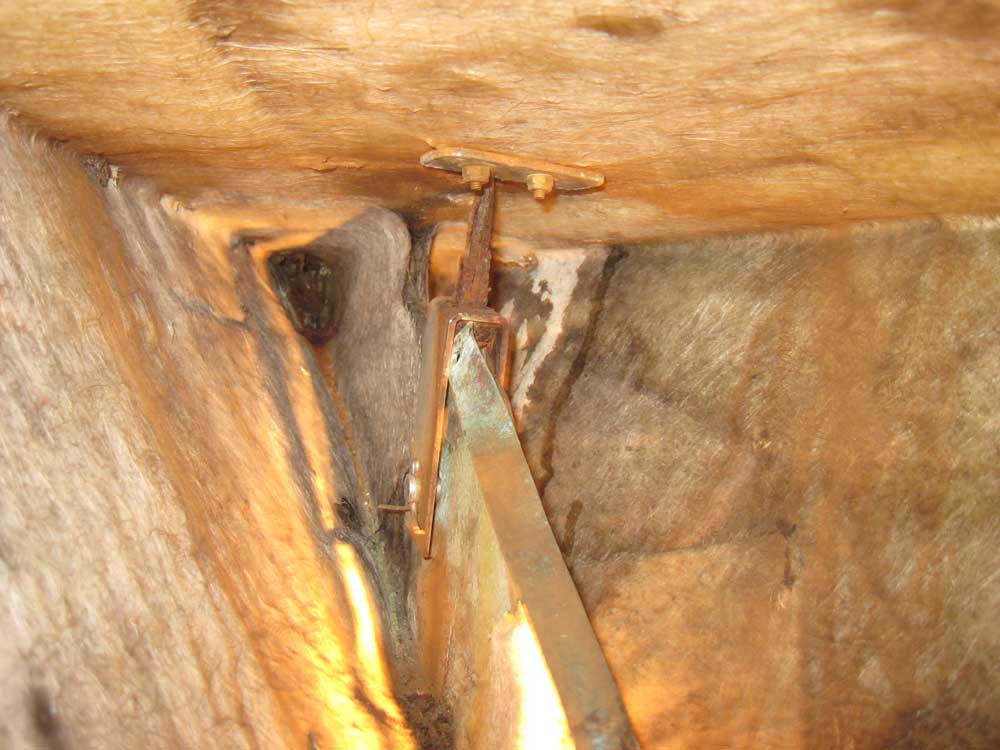
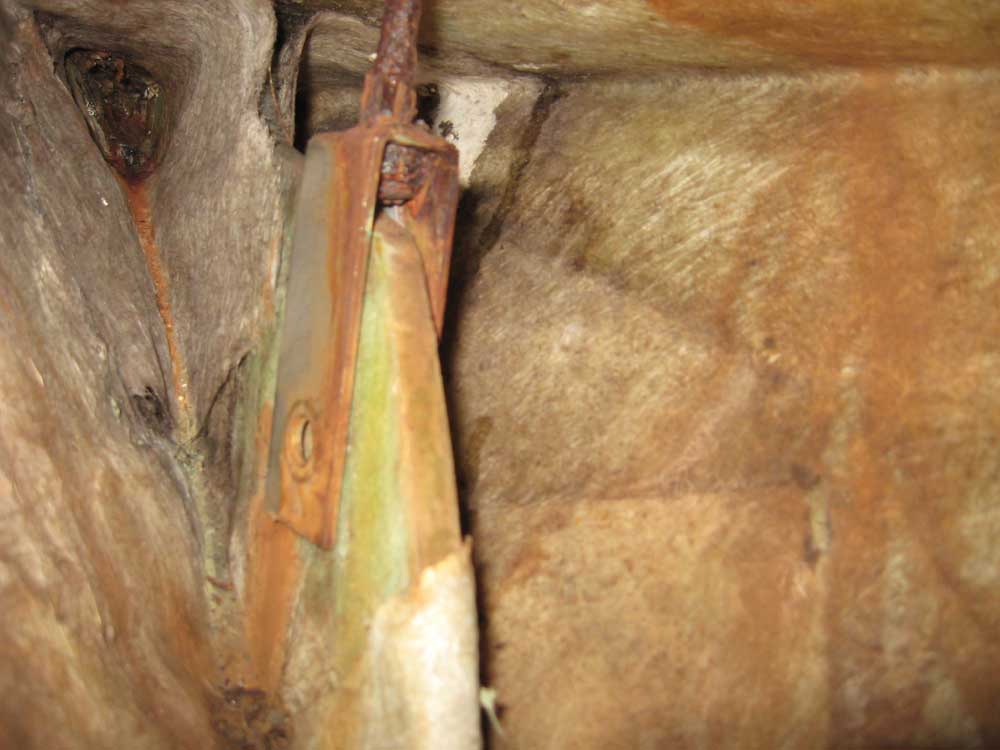
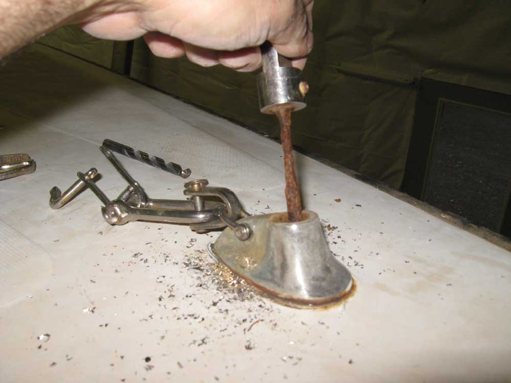
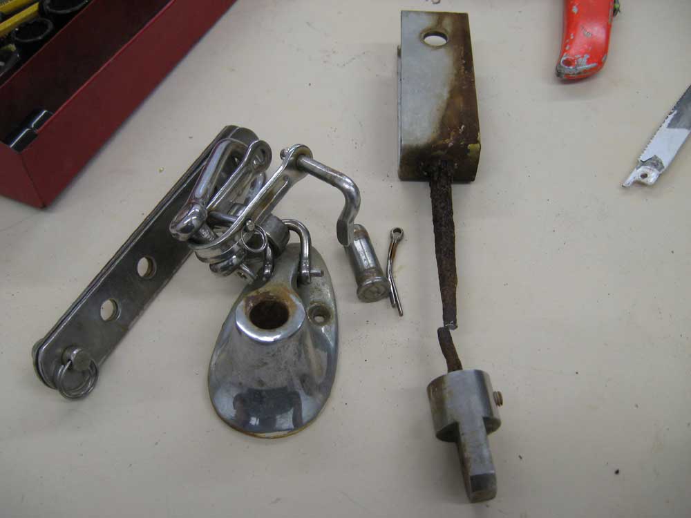
November 15, 2007 After a morning's work wrapping things up on another project (rather literally, actually), I got to work at lunchtime, and removed the headstay fitting. I found it was actually fairly roomy in the enclosed forepeak section, at least once I removed the large puddle of slimy water that'd accumulated there at some point in the rather distant past. The headstay fitting was secured to a knee in the stem with a clevis pin, which was easy to remove. But before I could remove everything, I had to remove the deck fitting. The badly corroded rod snapped easily when I twisted the end fitting with some Vice-Grips, and I could then remove both parts of the fitting. |
|
|
|
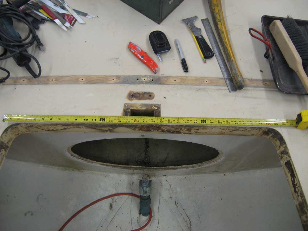
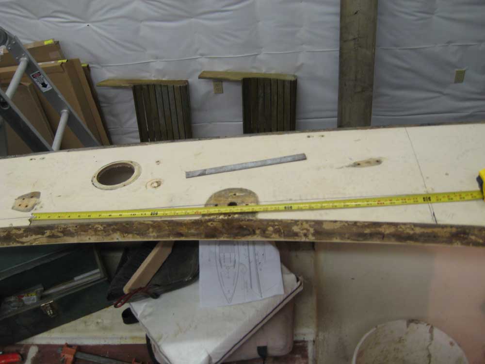
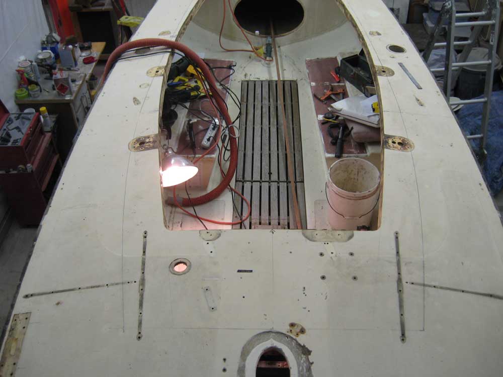
Next, I turned to some layout for the new cockpit shape and cabin trunk. I had a basic drawing from the owner with some dimensions, so I used that as a reference. First, though, I made a couple measurements of things as they existed, partly for the record and partly because the owner had specifically asked for a couple things. The aft end of the cockpit, as existing, is 33-5/8" in width (assuming the lines are brought out to create a corner rather than the rounded edge). |
|
|
|
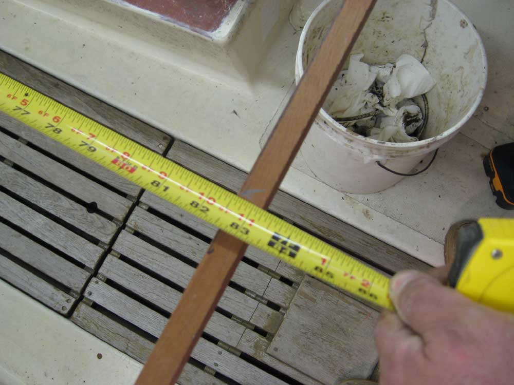
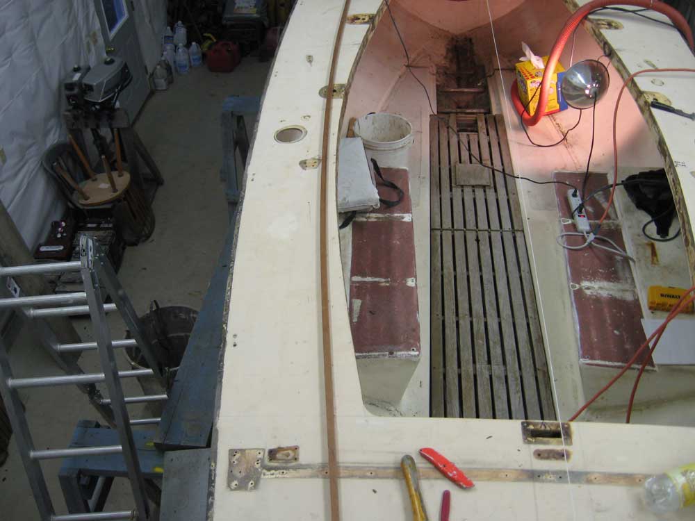
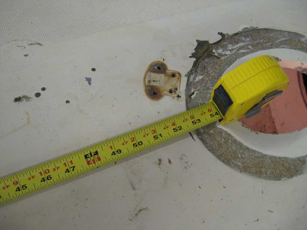
The tiller extends forward to a point about 45" from the aft end of the cockpit (measurement represented by the aft edge of the mahogany spline). In the second photo, you can see a mark I made on the deck to starboard, just aft of the orange vacuum hose. |
|
|
|
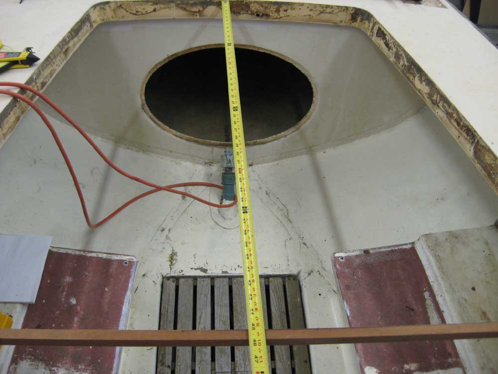
From the forward end of the tiller to the aft end of the proposed cabin trunk, the distance is 36-1/4". |
|
|
|
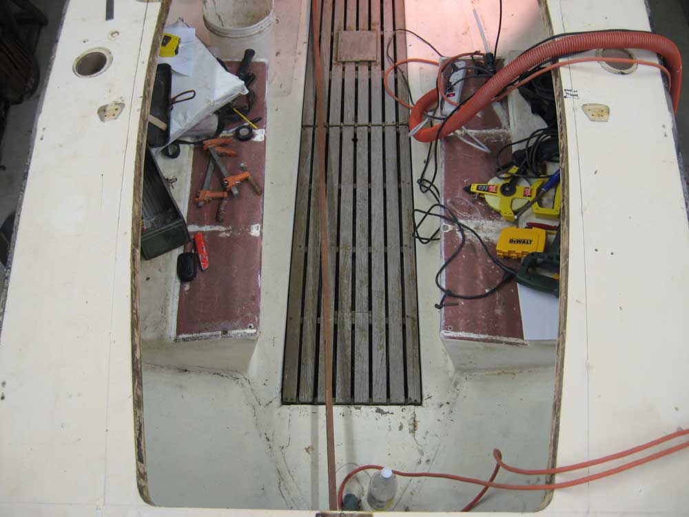
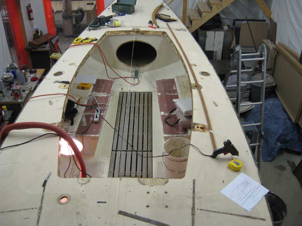
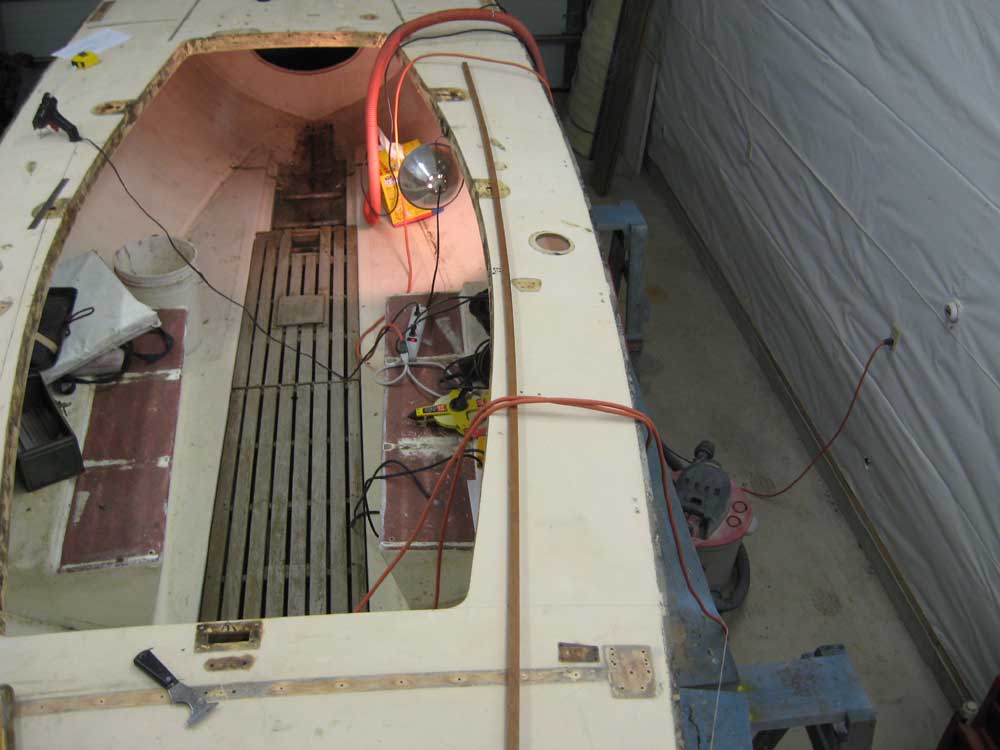
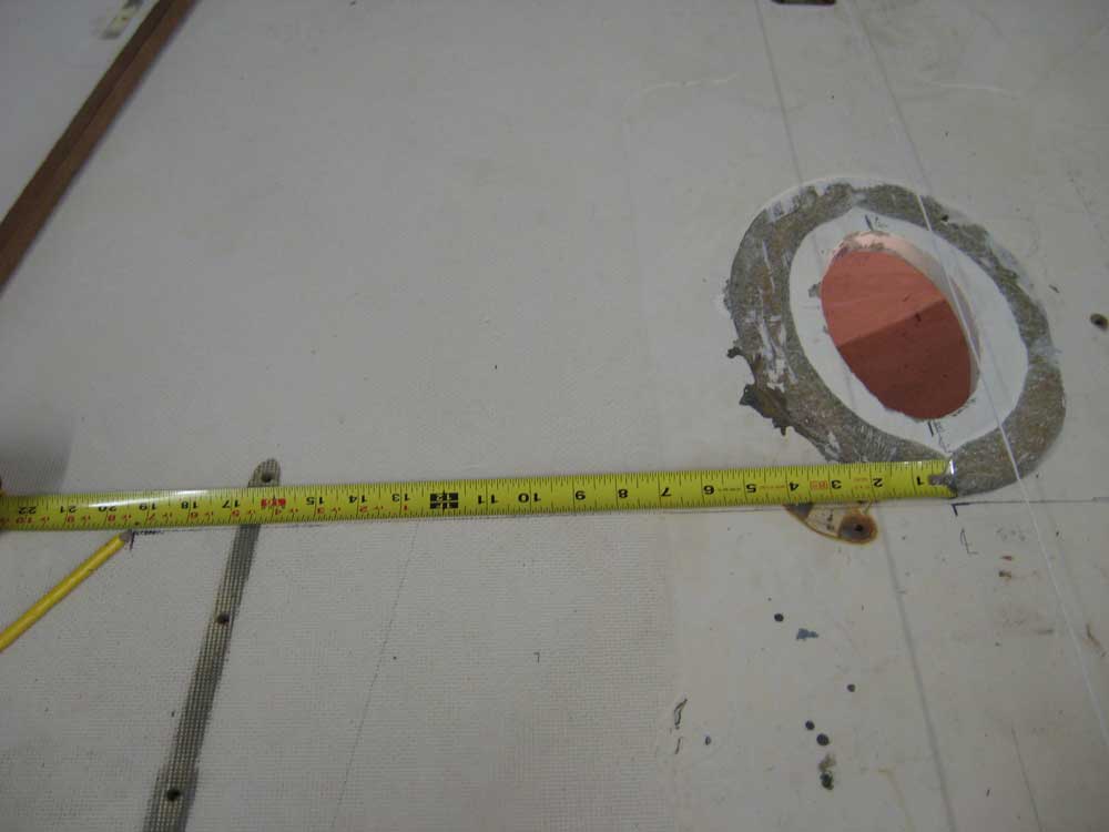
The concept for the new cockpit indicated that the outer edge would be 12" from the edge of the hull, maintaining a consistent width along its length. The overall length of the new cockpit, maintaining the existing after extent and extending forward to the future bulkhead defining the cabin trunk, was 6' 9-9/16". I measured this from the aft end of the cockpit, or more specifically from a point 1" aft of the cockpit where I could hook my tape, so the tape shows an additional inch on the measurement to accommodate the fact that the tape actually started 1" further aft than it should have. I used a batten to mark the location on each side deck, using equal measurements from the centerline at the aft end of the cockpit. In later photos, you may notice an athwartships line towards the forward end of the cockpit on each sidedeck; this is the proposed bulkhead location demarking the cabin trunk. |
|
|
|
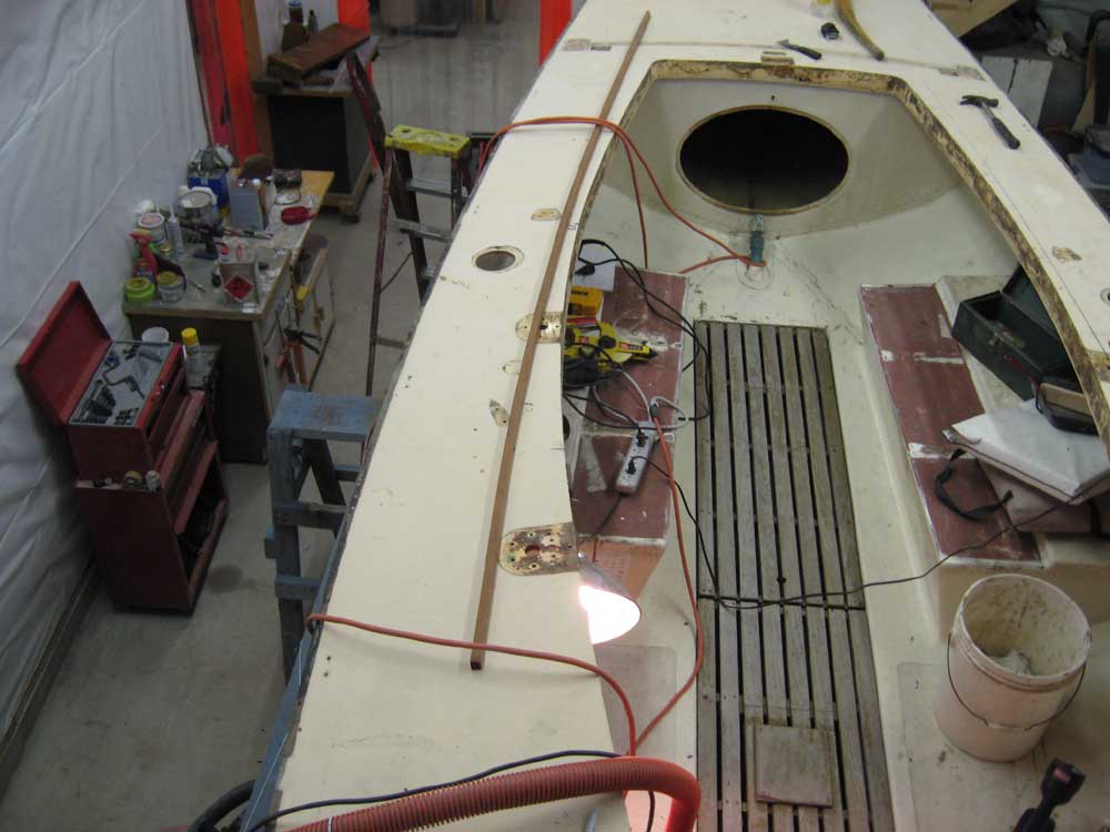
Using a steel rule for convenience, I marked out the 12" distance from the hull along both sides of the cockpit. Then, I used a mahogany spline to produce the curve between the points. I held the spline in place as necessary with hot melt glue, being sure to run the spline past the end points to ensure a fair curve. I began on the port side, and then repeated the process to starboard. |
|
|
|
In each photo, the inside (cockpit side) of the spline represents the line. I made dark pencil marks on the deck which you will see in subsequent photos of the layout. |
|
|
|
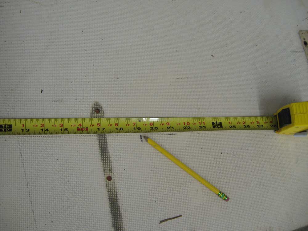
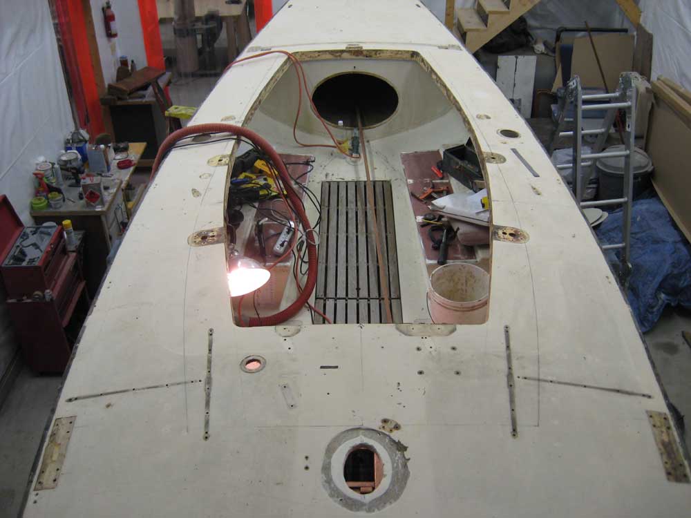
Next, I laid out the cabin trunk. Using the drawing as a general guide, I measured forward from my previously-determined aft mark and located the leading edge 4'-4-1/2" forward, or just behind the mast. I dispensed with an extra 1/16" shown on the drawing because a slightly shorter measurement actually fit in more appropriately with the mast partners. |
|
|
|
I tacked the batten back in place at the marks indicating the aft end of the cabin, and measured forward from there an equal distance on each side so that I could draw in the athwartships line demarking the leading edge. Then, I measured from centerline out 19-1/4" to each side, for a total width of 3' 2-1/2". The cabin trunk would taper inward along its length as it extended forward for a more interesting appearance, rather than simply paralleling the deck edge like the cockpit. |
|
|
|
Finally, I used the spline to lay out the curves on each side. I held the spline in place along the previously-drawn cockpit lines with some clamps, and bent it to the marks I just made above, and traced the curve onto the deck. You should be able to see the lines in these photos. |
|
|
|
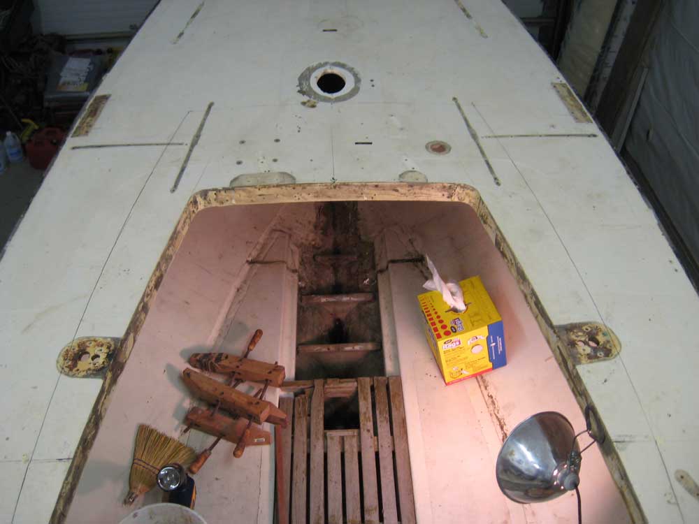
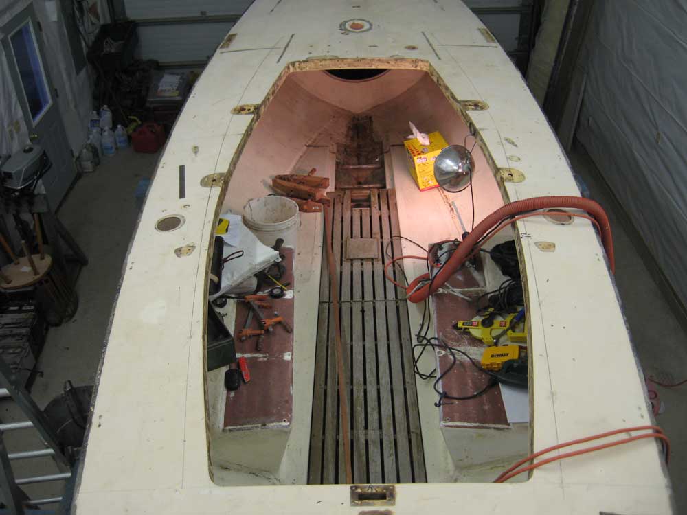
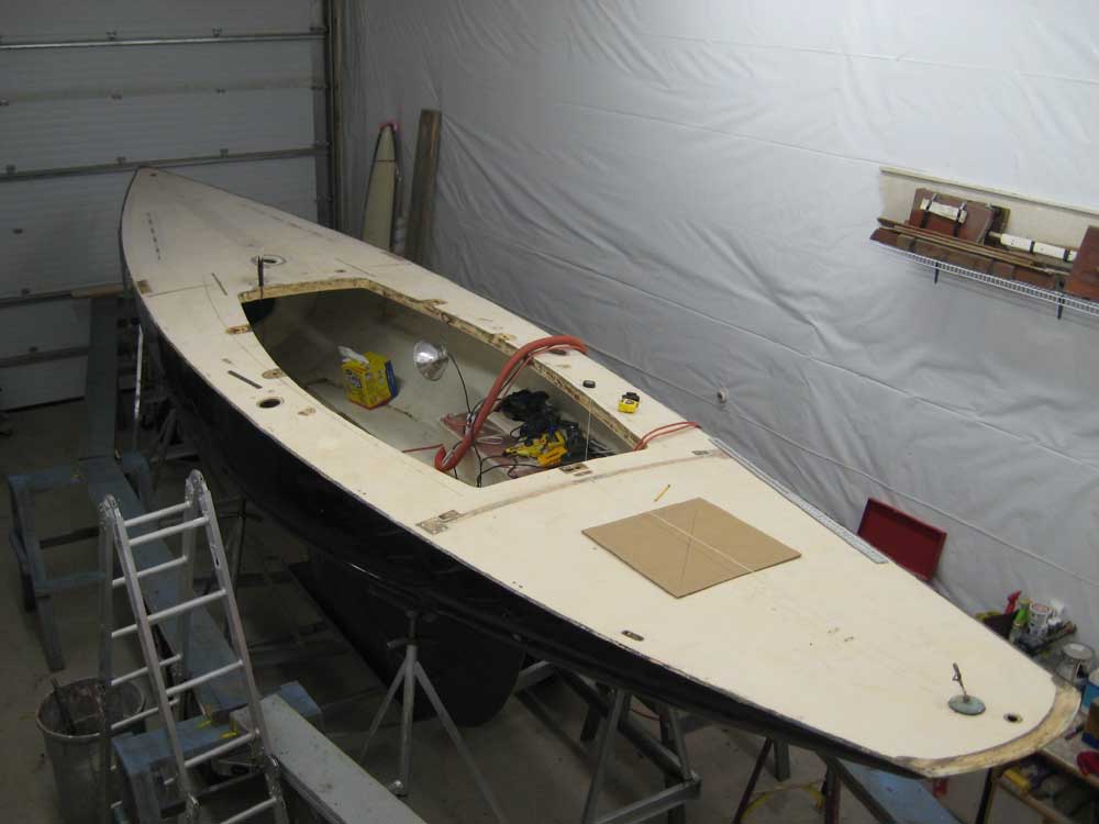
Here are some additional photos showing the entire cockpit and cabin trunk layout from a few angles. |
|
|
|
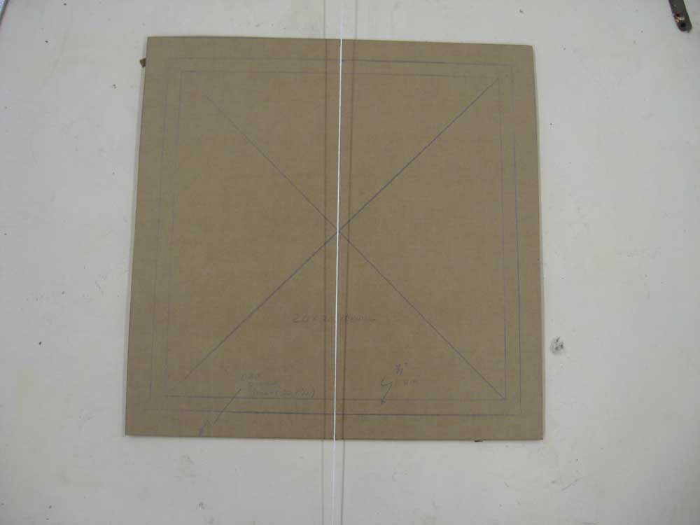
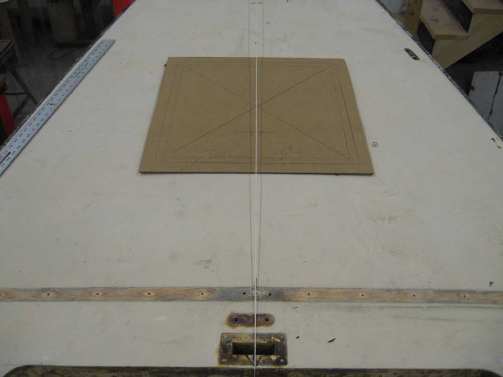
I thought the lines looked fairly pleasing for a rough layout. The additional width in the cockpit, particularly at the aft end, would be a nice change to allow for just a bit more elbow room. Finally, I made a cardboard template for a proposed aft deck hatch. The template shows a 20" square clear opening, with a 22" overall size when the inner rail exterior dimensions of the hatch cover are taken into account. These marks are visible on the template, though they don't show up that well. The forward edge of the hatch (the exterior dimension, not the cutout) is 20" aft of the end of the cockpit here. This location would require removal--and likely replacement--of a vertical support within the open space beneath. Two new such supports could easily be secured, one on either side of the opening, to provide the modicum of stiffness afforded by the existing support. |
|
|
|
|
|